1. Introduction
A volute is a typical collector used in centrifugal pumps. After the water leaves the impeller and proceeds to flow in volutes, as no external forces work on water, its mechanical energy cannot increase, and as hydraulic losses in the volute are inevitable, pump efficiency will decrease due to energy dissipation. Experiments have revealed that losses stemming from volutes can account for half of the total losses of the pump [
1,
2,
3,
4,
5]. It is evident that making efforts to improve the design approach for volutes is an important measure to save energy and reduce the operating costs of pumps.
As the hydraulic performance of centrifugal pumps is closely related to volute flow, extensive studies were conducted in the past by applying analytical, numerical, and experimental approaches to volutes. Many engineers have made every effort to develop innovative methods for volute design to improve the volute operating characteristics. Alemi et al. conducted research on two volute design methods and found that the constant velocity method offered better results [
6]. Chan et al. compared two traditional volute design methods and obtained a conclusion similar to that of Alemi [
7]. Kim et al. formulated new volute design methods that were based on the numerical analysis proposed by Stepanoff’s theory [
8]. Wang et al. found that the length of the wetted perimeter of the cross-section is mathematically proportional to the friction loss in the volute, and therefore a new energy-saving volute design method is proposed [
9]. Chan et al. compared two different design techniques that are conventionally used in the design of volutes for centrifugal pumps and found that the imbalanced forces due to the geometry of the volute need to be taken into consideration, especially in centrifugal pumps [
7]. Zhang, Alemi, and Lu et al. discussed the influence of the shape, position, and setting angle of the volute tongue on hydraulic performance and pressure pulsation of a centrifugal pump [
10,
11,
12]. Allali and Tan et al. discovered that different shapes of volute cross-sections (circular, rectangular, and trapezoidal) had different effects on flow velocity and pressure variation in volutes [
13,
14]. Dehghan et al. designed new types of volutes using two different theories and proposed that each method had its own advantages [
15]. Yan et al. developed a new volute and a new impeller with splitter blades to improve the hydraulic characteristics of pumps [
16]. Yang et al. created a novel volute design method for high-efficiency pumps by changing the volute geometrical parameters. As using double volutes for pumps is an effective way to reduce radial thrust on impellers, a lot of studies are performed on double volutes [
17]. Zhou and Kang et al. discovered that a double volute not only reduced the radial force but also reduced the pulsation amplitude of the impeller during pump startup [
18,
19]. Wang et al. conducted theoretical analysis and numerical simulation to explore radial and axial thrust on the impeller of an aviation fuel pump and found a relation between the pump discharge and axial as well as radical thrusts on the impeller [
20]. Mina et al. performed experiments on three pumps with single, double, and triple volutes and discovered that two and three volutes remarkably reduced the force on impellers as the operations deviated from the beat efficiency point [
21]. Tao et al. found that larger volute sections reduced the radial thrust on the impeller and the pressure pulsation in the volute [
22]. Miao and Shah et al. discussed the effect of volute collectors on the performance of centrifugal pumps based on entropy generation analysis [
23,
24]. Khalifa and Bairio et al. studied the flow pulsation related to the interaction between impeller blades and different types of cutwaters using computational fluid dynamics (CFD) technology and suggested that a rounded cutwater would reduce the strength of pulsation in volutes [
25,
26]. Wang et al. analyzed the Coriolis force acting on the fluid in the disc impeller and volute, calculated the work conducted on a unit mass of liquid by this force, and showed that the work performed by the Coriolis force generates the head of water in the disc impeller [
27]. It is apparent that all the above-mentioned achievements in volute research are beneficial for engineers to profoundly understand flow behavior in volutes and formulate innovative design guidance for volutes.
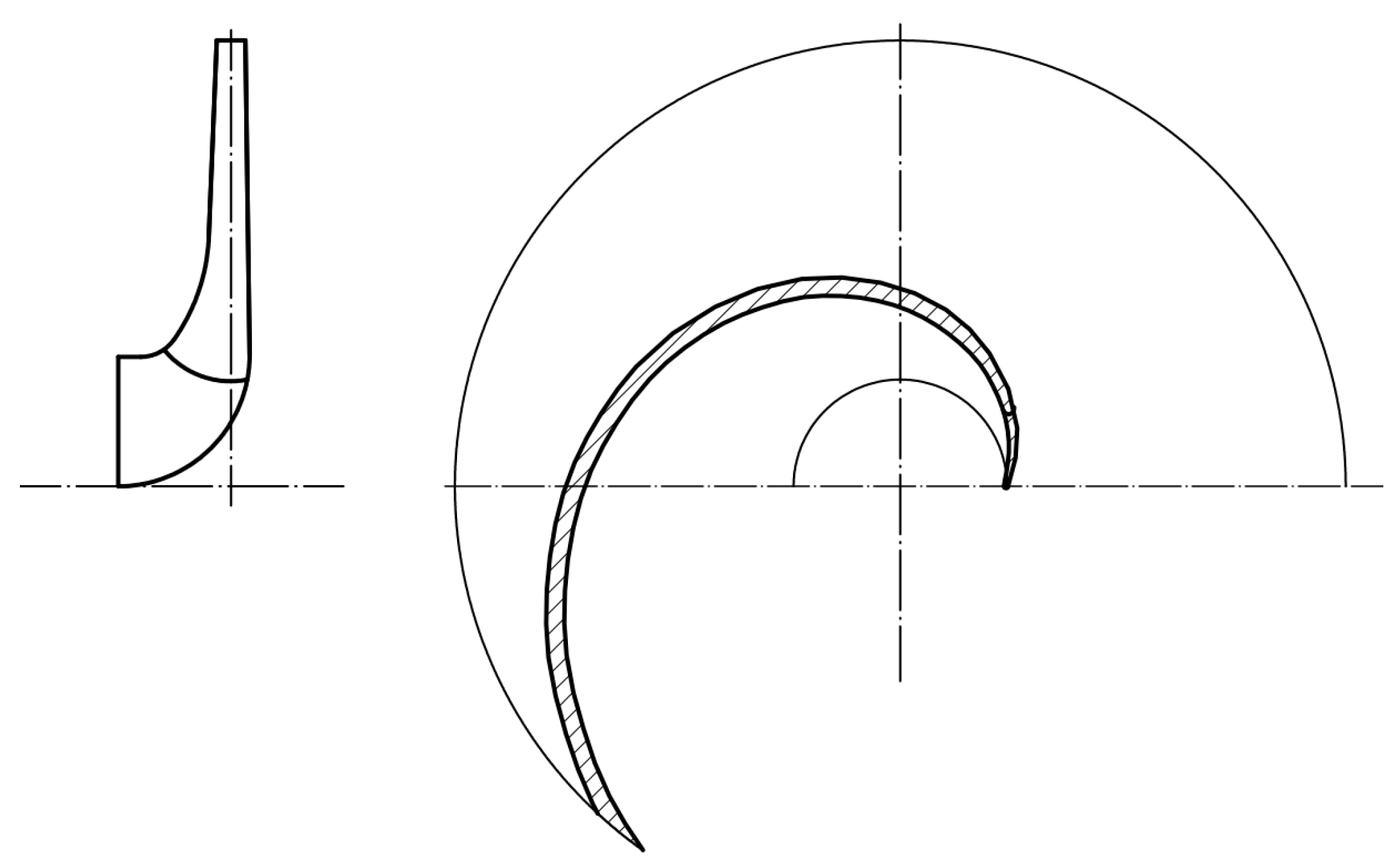
The main portion of a pump casing is a spiral volute with increasing cross-sectional areas, which is positioned around the impeller and is of great significance for volute hydraulic performance. The flow inside the volute is continuous, but in volute design practice, it is necessary to establish the dimensions and shapes of eight meridional cross-sections of the volute, and the angles between any two adjacent cross-sections are 45° in a single volute that is extensively used. These cross-sections primarily determine both the volute geometrical shape and hydraulic losses in the volute. The positions of the eight cross-sections are illustrated in
Figure 1. A Meridional section of the volute and impeller is illustrated in the right-hand corner of
Figure 1, where
b2 and
b3 are the outlet and inlet widths of the impeller and volute, respectively. The thick line denotes the wetted perimeter of the volute cross-section.
Two geometrical parameters in the volute meridional sections are closely related to volute performance; however, based on the literature review, they did not attract enough attention in the past [
9]. These two parameters refer to the wetted perimeter
χ of the volute cross-section and the volute inlet width
b3, which should match the outlet width
b2 of the impeller; namely, the water from the impeller should smoothly enter the volute without significant hydraulic losses. Improving the method of determining these two volute geometrical parameters is a key measure to improve volute performance.
The hydraulic losses,
hf, arising from a non-circular straight duct can be determined using the Darcy formula:
where
l represents the duct length,
dh represents the hydraulic diameter of the non-circular cross-section of the duct, and
dh = 4
F/
χ in the above formula.
F denotes the area of the cross-section;
v represents the average velocity of the flow;
v =
Q/
F;
Q is the flow rate through the cross-section; and
λ is a dimensionless coefficient determined by the relative roughness of the duct wall and the Reynolds number of the flow. Equation (1) can be rewritten as follows:
The spiral volute is not a duct with unchanged areas for all cross-sections. But the friction losses of flows in volutes and pipes result in the same reasons, and Equation (2) can be applied to analyze the friction losses in volutes. The flows in every wetted part of a centrifugal pump are fully turbulent, which is why coefficient λ is the only function of the relative roughness of the pipe wall and has nothing to do with the Reynolds number. F and l in Equation (2) are constants decided by the volute structure. It is evident that when the flow rate Q is given, the friction losses hf are proportional to the wetted perimeter χ of the cross-section. Equation (2) also indicates that when the areas of the cross-sections are constant, the shapes of the cross-sections do not have direct influences on the friction losses of the flow in the volute. The wetted perimeters of cross-sections with identical areas and different shapes are not identical, and the friction losses through these cross-sections are different due to the varying values of the wetted perimeters. This phenomenon must be taken into account in the volute design practice.
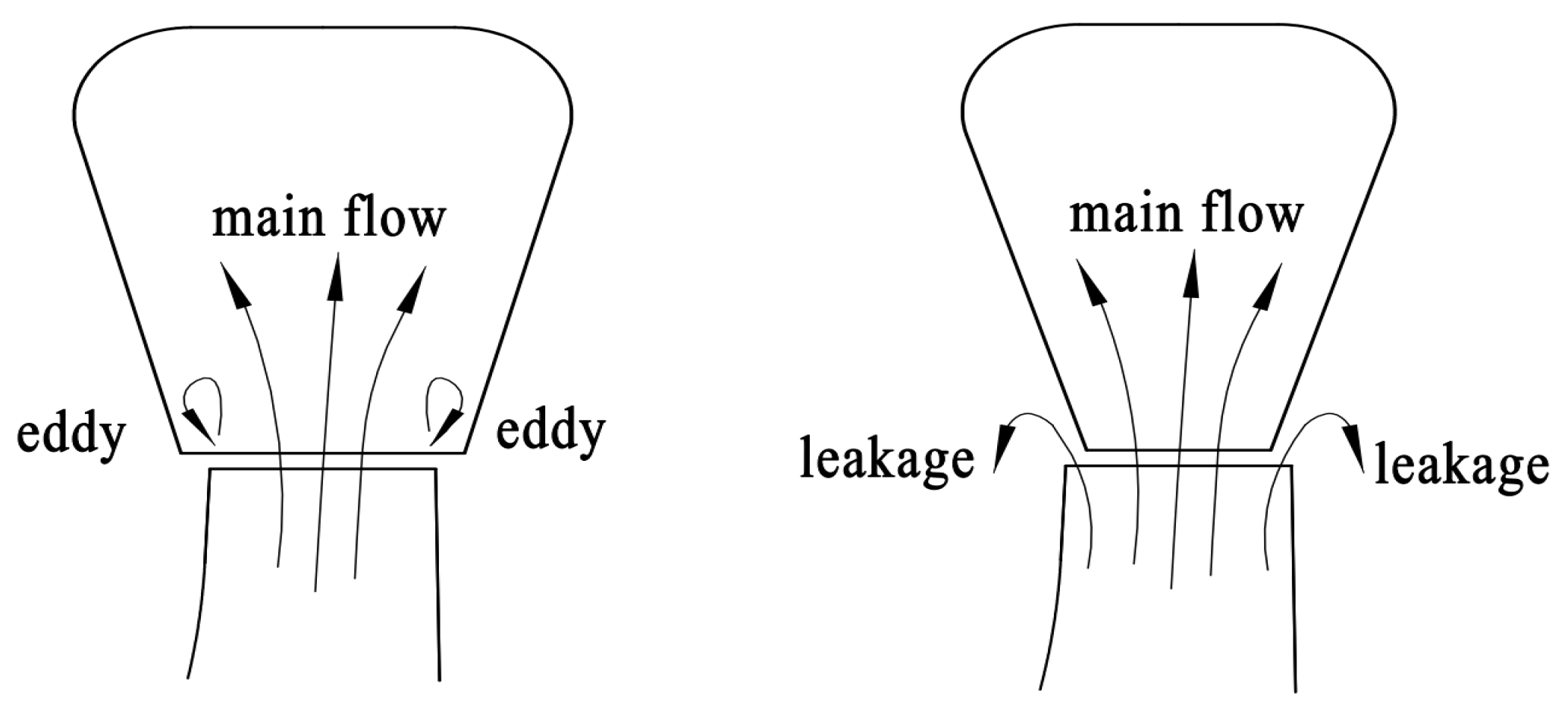
When water leaves the impeller and enters the volute, if the flow in the meridional section diverges significantly, two eddies may occur at the lower portion of the volute. Although circles have the shortest perimeters in plane figures with identical areas, circular cross-sections were hardly applied to pump volutes to avoid such eddies.
In the design procedure of a pump, the hydraulic design of the impeller was completed before the volute design commencement, and the outlet width b2 of the impeller was a known parameter when determining the inlet width b3 of the volute.
It is assumed by some pump designers that the ratio of
b3 to
b2 has a significant impact on the flow at the volute entrance, and they believe that if
b3 is excessively large, as pointed out previously, water may diverge in the meridional section after it enters the volute, resulting in separation, as illustrated in
Figure 2 (left). Conversely, if
b3 is too small, a fraction of the exit flow cannot enter the volute and is lost through the shroud and hub clearances, which causes volumetric losses, as illustrated in
Figure 2 (right).
Two dominant approaches are extensively used to determine eight cross-sections of volutes: the theorem of conservation of the angular momentum and calculation based on statistical data. These are two independent methods comprising different flowing theories and design processes.
When applying conservative law, the flow in the volute is regarded as a free vortex. Conservative law states that the product of the circumferential component
Vu of the absolute velocity of a water particle and the distance r from the particle to the impeller axis is considered a constant, and this constant is identical to the angular momentum at the impeller outlet. Except for some regular cross-sections, such as rectangles, it is impossible to obtain analytical solutions for the dimensions of general shapes. The authors of this paper once applied this approach and designed volutes for several pump companies by programming, and results arising from the tests of products revealed that in a large range of overload conditions, sometimes even at the design point, the heads generated by pumps and pump efficiencies dropped remarkably [
28,
29,
30]. In addition, the areas of the cross-sections designed by the conservative law were always smaller than those of the volutes of high-efficiency pumps. Defects in products stem from defects in the design principles. Only when the torque acting on the liquid particles about the impeller axis is zero can the conservative law be applied to the liquid. This occurs only in desirable liquids without viscosity, and the flows are actually laminar, and the viscous force of real liquids causes friction on water particles at different velocities. Since the torque acting on the liquid elements exists due to friction, the conservative law cannot hold in this case. It can be seen that real liquids in volute cannot satisfy the conditions of the conservative law. Based on this law, the velocity isolines on a cross-section should be parallel to the impeller axis, but the measured liquid velocity distribution did not conform to the hypothesis, as illustrated in
Figure 3. In
Figure 3, the design flow rate and the head of the tested pump are 430 m
3/h and 11.7 m, respectively. Based on the conservation of angular momentum, the velocity isograms on the cross-section should be straight lines, and at intersections of straight lines and volute sidewalls, the circumferential component velocity
Vu is not zero, but the liquid on the sidewalls is actually at rest due to the viscosity of real liquids.
Vu is the velocity component perpendicular to the volute cross-section, which denotes the flowing capability of the volute. The conservative law assumes that, within the boundary layer on the volute sidewalls, the value of velocity is the same as that in the core flow. As the conservation theorem exaggerated the flowing capacity, the calculated areas of the cross-sections were naturally smaller. Under overload conditions, as the flow rates increases, the velocity increases through small cross-sections. Because the hydraulic losses of liquid are proportional to the square of the flow velocity, the head generated by the pump and pump efficiency dropped in the overload range. Due to the drawbacks of the conversational theorem, its practical application is limited.
The correctitude of the above-mentioned analysis was further justified by numerical calculations conducted by the authors. To reduce the wetted perimeters and friction areas of volutes, single circular arcs were used on the upper parts of the volute cross-sections to replace the traditional line segments. The geometrical parameters of the eight volute cross-sections were obtained by the application of numerical simulation based on the conservative theorem. The velocity distribution calculated later did not conform to the conservation of angular momentum, as illustrated in
Figure 4.
At the best efficiency point of the simulated pump, the flow rate, head, and rotational speed were 75 m
3/h, 82 m, and 3000 r/min, respectively. In
Figure 4b, three horizontal lines A-A, B-B, and C-C are located on the eighth cross-section of the volute of the mentioned pump, and
Figure 4a displays the velocity variation along the three lines at the design point. It can be seen that although the velocity on horizontal line A-A at a small radius was greater than that on line C-C at a larger radius, the speed was not constant, and the average value of velocity did not satisfy the magnitude arising from the conservative theorem. At the intersection points of the three lines and volute sidewalls, the speed of flow approached zero quickly. These phenomena were consistent with the above analysis.
A design approach based on statistical data is a generalized similar design method. Pump researchers have intensively investigated the hydraulic characteristics and geometrical properties of the wetted parts of pumps with high performance and published their achievements [
9]. By applying statistical methods, they identified the relationships between all important geometrical parameters of pumps, such as impeller outlet diameters, areas of volute cross-sections, and specific speeds of pumps. These relationships are often expressed using empirical formulas or charts based on regression analysis. The approach that takes advantage of statistical data is characterized by the following features. As the statistical data involved in the approach stem from efficient pumps, the obtained results based on the data are helpful to improve the pump performance. Since different experts dealt with different samples of advanced pumps, and they may process the data based on different principles and methods, the geometrical parameters of the wetted parts finally obtained may not be the same if different statistical data are applied by pump designers.
2. Introductions and Comments on Two Types of Statistical Data Applied to Volute Design
References [
31,
32] describe two types of statistical data on the volute design. Both types of data are extensively used by most pump designers, and they are their main design tools for pump designers. As pointed out previously, even for the same specified task, the dimensions of the wetted parts may be different based on different statistical data. These two types of data are introduced as follows: the main tasks in volute design consist of establishing eight meridional cross-sections of the volute, and two different methods are used to achieve the goals using two types of statistical data.
Based on references [
31,
32], the area
A8 of the eighth cross-section, namely the largest cross-section, should be first determined,
, where
GPM is the flow rate at the design point, gal/min,
H is the head, ft, and the finalized
A8 is in the spin. The coefficient
K3 can be found in
Figure 5, where
, and
n is the rotational speed of the pump, rpm.
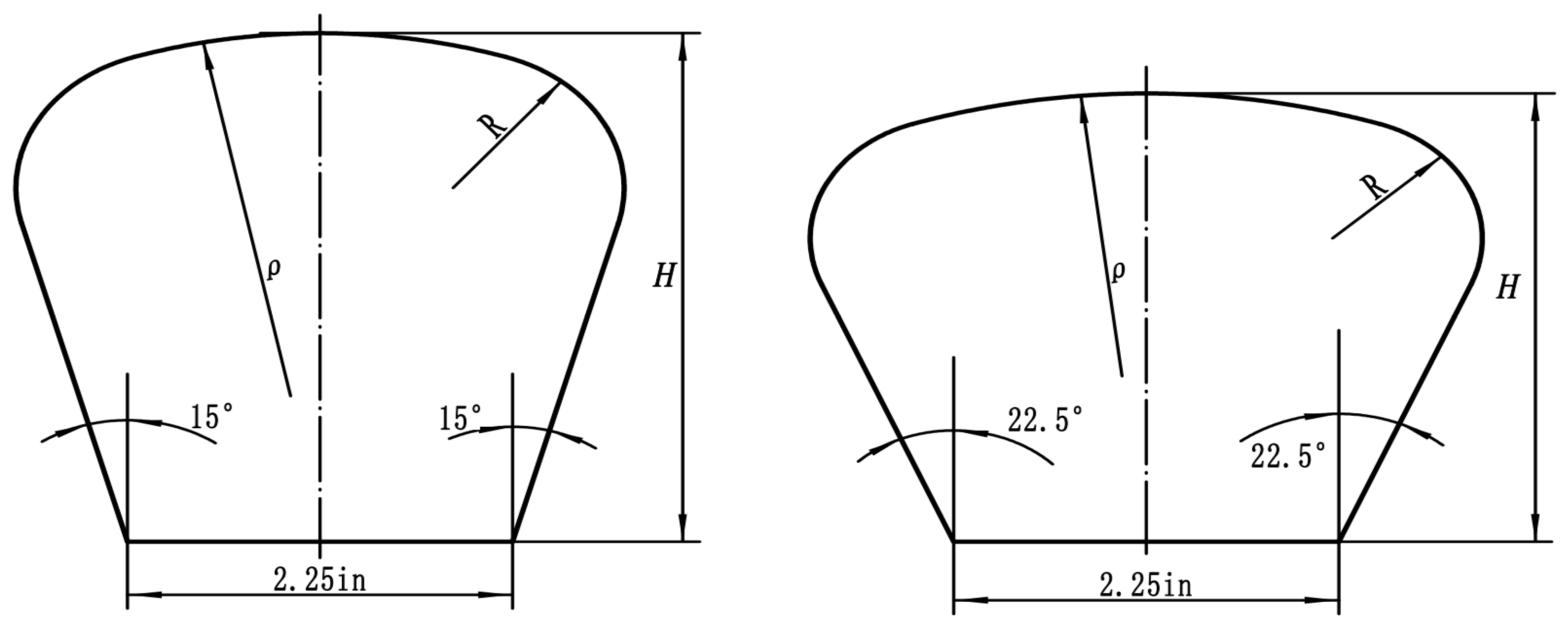
The shapes of the volute cross-sections are standardized in the design procedure described in Ref. [
31]. The angles between the two sides of the cross-sections remain unchanged at 30° or 45°. An angle of 45° is used for the pumps with a higher specified speed, as illustrated in
Figure 6. The factor
F is determined as
. The volute inlet width
b3 can be calculated as follows:
, in; height of each cross-section,
H, in; the radius of a single circular arc
ρ on the upper part of the cross-sections, in; radius
R for transition, in, can be obtained using the descriptive data in
Table 1 times the factor,
F [
31]. In
Table 1, subscripts 1, 2, 3, …, 8 denote the number of volute cross-sections.
It is not necessary to calculate the areas of the other seven cross-sections from the first to the seventh one when using the statistical data presented in Ref. [
31].
The design approach presented in Ref. [
31] is characterized by the following features. The volute inlet width
b3 cannot be specified by designers. A circle has the smallest perimeter of all the plane figures within the same area. A single circular arc is used to replace the traditional line segment on the upper part of the cross-section, which means that the founders of the statistical data attempted to reduce the wetted perimeters and friction areas of the cross-sections.
The first step in the design procedure described in Ref. [
32] is used to obtain the areas of the eight cross-sections. The eighth cross-section has the largest area of
A8,
, where
Q is the design flow rate, m
3/s,
H is the design head,
m, and
g denotes gravitational acceleration,
g = 9.8 m/s
2. Coefficient
K3 is shown in
Figure 7. In
Figure 7, the specific speed
. The areas of the other seven cross-sections can be calculated based on the following formula:
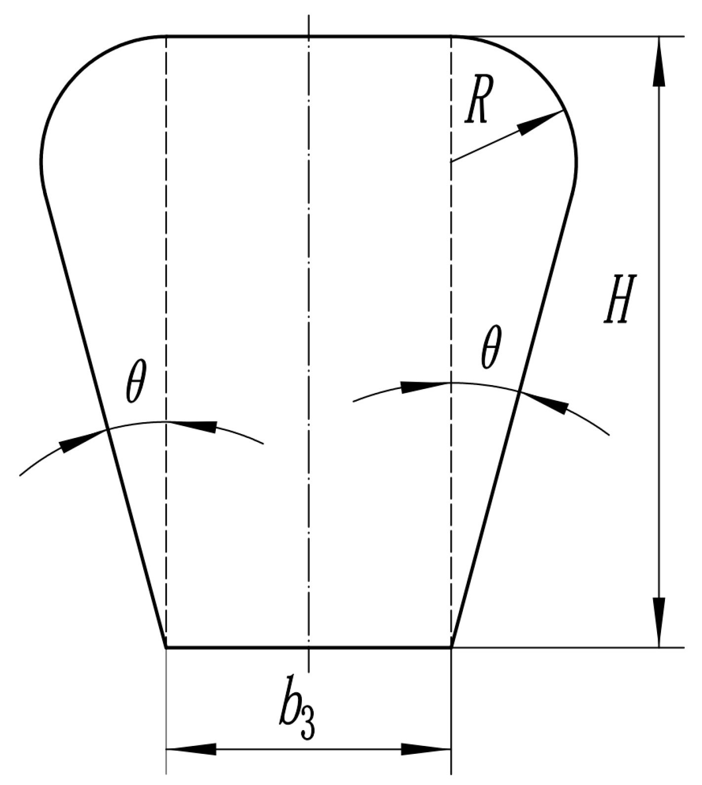
). The shapes of the eight cross-sections are all trapezoids with two rounded corners. The angles between the two sides of the trapezoids should remain unchanged. A larger angle can be used for pumps with higher specific speeds, but an excessively large angle may result in flow separation at the volute inlet. When designers determine the inlet width
b3 of eight cross-sections, they should take the outlet width
b2 of the impeller and long experience into account. The centers of the transition arcs for filleting the trapezoid corners are located on the lines perpendicular to the trapezoid baseline, as shown in
Figure 8. Eight arc radius
Ri can be obtained based on the following Equation (3), where
Fi represents the area of a cross-section, and
θ represents half of the angle between the two sides of the cross-section.
Figure 5 and
Figure 7 are used to obtain the coefficients in different formulas and are copied from different references.
The heights of cross-sections Hi are .
The design approach described in Ref. [
32] is characterized by the following features. The inlet width
b3 is specified by the designers. Every cross-section has a line segment on the upper part of the figure, which means that in this design, no attempts were made to reduce the perimeter and friction area of the cross-sections.
A lot of calculations revealed that the areas of two eighth cross-sections based on two types of statistical data are similar for the same given flow rate and head; in other words, the average velocities in the two types of volutes are almost the same. This phenomenon indicates that, although the two approaches are based on different statistical data stemming from different pump samples, the flows in the efficient pumps are similar.
The approaches based on statistical data assume that the velocity of water in volutes is constant, which is a property of turbulent flow. In a turbulent flow, liquid particles change their momentum by colliding with each other, making the particle momentum uniform. The design approaches based on statistical data reflect the flowing feature of turbulent flow.
As two types of statistical data for volute cross-section design existed in the past, engineers sometimes feel confused when they begin to design volutes because they do not know what type of statistical data should be applied. This paper offers references and suggestions for pump designers to solve this problem.
3. Comparison of Numerical Calculations of Two Types of the Volute
This paper described volute design approaches based on two types of different statistical data, both of which are extensively used in design practice. It can be seen that as different principles are applied to reduce hydraulic losses in volutes, the geometrical shapes of the two types of cross-sections are quite different, and the degrees of hydraulic losses are also different in the two types of volutes. We designed three different impellers for three pumps with different design flow rates and heads. Based on two types of statistical data, we then designed two volutes for each impeller. Then, we simulated the flows in the pumps by applying CFD technology to find out the most effective method for volute design. In fact, CFD technology is extensively applied to investigate the behavior of internal flows within the wetted parts of all kinds of pumps, and it is acknowledged that this approach is an effective way to improve pump performance characteristics [
33,
34,
35].
To validate the reliability of the numerical simulation, a pump was tested in a closed test rig. The pump tested was designed and manufactured by the Fluid Machinery Research Institute at Jiangsu University, China, and the test rig was also located at this institute. The wetted parts of this pump were conducted based on the geometrical dimensions measured for the pump. After that, the hydraulic characteristic curves were plotted in accordance with the simulated results. It is evident that, if the performance characteristic curves stemming from the tests and numerical simulations are similar, it is safe to say that the simulating method is reliable. The specific speed
Ns of the pump was 1877.5, where
, flow rate
Q was 21,450 gal/h (81.2 m
3/h), head
H was 91.87 ft (28 m), and rotational speed
n was 3000 r/min. The main measured dimensions of the impeller and volute of the tested pump are listed in
Table 2.
Based on the geometrical parameters measured for the impeller and volute in
Table 2, 2D diagrams of the impeller and volute were drawn. Further, 3D models of the impeller, volute, and suction nozzle were completed using Unigraphics NX 12 software, which constituted the entire computational domain. For the stable flow, the inlet pipe and discharge nozzle were extended to four times the pipe diameter. Structured hexahedral grids of the computational domain were meshed by using ICEM 2022 software, and the impeller inlet, outlet, and cutwater were refined, as illustrated in
Figure 9.
In this paper, the standard k-ε turbulence model was used to solve the internal flow characteristics of the centrifugal pump. The Y+ value of the grid node from the wall should be controlled within the range of 30 < Y+ < 300, which can meet the requirements of the grid in the near wall area [
36].
Figure 10 shows the Y+ value of the near wall area of the model. It can be seen from the diagram that Y+ is within the allowable range, and the boundary layer grid is set properly, which can improve the grid significantly.
The number of grids in the computational domain has a significant influence on the numerical results. The independence of the solution was explored, as shown in
Table 3.
Table 3 indicates that when the grid number exceeded 1.2 × 10
6, the head developed by the pump and pump efficiency remained unchanged.
Numerical calculations for multiple working conditions were carried out using ANSYS CFX. In the calculations, multiple coordinate systems were used. For the rotational flow field and other wetted parts at rest, rotative and stationary coordinates were utilized, respectively. The interfaces between the stator and rotor were selected as the frozen rotor mode. Clean water at 25 °C was used as the medium. The time-average Navier–Stokes equation was used as the governing equation. Non-slip boundary conditions were selected for the solid walls and the
k-ε turbulent flow model was applied to the walls to obtain accurate results. The pump inlet and outlet boundary conditions were mass flow rate and static pressure, respectively. The rotational speed was the same as that used in this test. Different performance characteristics were obtained by changing the mass flow rate through the pumps. The computational convergence accuracy was selected as 10
−6. Two efficiency-flow rate curves, two head-flow rate curves, and two shaft power-flow rate curves based on the experimental and numerical results were shown in
Figure 11, where the pump rotational speed was 3000 r/min. It can be seen that the two curves in each group are consistent, and the distribution of the same performance parameters under different conditions is uniform. The changing trend of the performance characteristics originating from the experiments and calculations are the same as those of the growing flow rates. Over the entire load range, the head deviations between the two curves are small, whereas the differences in efficiencies and input power are obvious, which means that the differences in hydraulic losses and hydraulic efficiencies are limited, and the difference in total efficiency is mainly due to the differences in mechanical and volumetric losses. The above-mentioned phenomena can almost be observed in all similar studies. To reduce the axial thrust acting on the rear shroud of the impeller, six balancing holes were bored in the rear shroud, but this detailed structure was neglected in the impeller model, and the volumetric efficiency was increased. At the impeller inlet, an annular gap must be set up between the rotative impeller and stationary pump casing, but when constructing 3D models of wetted parts, this gap was not considered, and the volumetric losses generated at this position were ignored. This effectively increased the total efficiency of the pump under all the working conditions in the numerical calculations. In terms of the above analysis, it is safe to say that the methods and results in establishing models, dividing grids into computational regions, and setting boundary conditions are reliable, and the results of numerical simulations, especially the hydraulic efficiencies, are believable.
Performance parameters at the design points of three pumps for numerical calculations are listed in
Table 4.
The main geometrical parameters of the three impellers are listed in
Table 5. Their impellers were designed independently based on commonly used design guidelines.
Cylindrical blades were used for pump A. A meridional section and a plan view of blades are illustrated in
Figure 12 based on the relevant dimensions listed in
Table 5.
Based on the two different volute design approaches described in [
31,
32], two different volutes were established for each impeller. As pointed out previously, the volute inlet width
b3 and wetted perimeter
χ of the volute cross-sections are two key parameters related to volute hydraulic performance. The
b3 and
χ values determined by the two types of statistical data were different, as shown in
Table 6. The cross-sectional shapes of the volutes are shown in
Figure 6 and
Figure 8, based on [
31,
32].
Based on the step-by-step procedures stated previously, after the 3D models of the wetted parts of the three pumps were completed, the computational domain was meshed, both inlet and outlet boundary conditions were set up, and the hydraulic performance curves of the three pumps were obtained by applying numerical calculations. The simulating processes mentioned above were the same as those previously described for the tested pump. The two head-flow rate curves and the two efficiency-flow rate curves of each pump reflect the different hydraulic performances of different volutes, as shown in
Figure 13,
Figure 14 and
Figure 15.
The two
H-Q curves and two
η-Q curves for pump A are shown in
Figure 13. The two
H-Q curves and two
η-Q curves for pump B are shown in
Figure 14. The two
H-Q curves and two
η-Q curves for pump C are shown in
Figure 15.
Two volutes, based on the two types of design statistical data and an unchanging impeller, were applied to each pump. From
Figure 13,
Figure 14,
Figure 15 and
Figure 16, it can be seen that although the heads and flow rates at the design points were completely different for the three pumps, the hydraulic performance characteristics stemming from the two types of volutes showed consistent variation trends. Over the entire range of flow rates, including the design point, head, and efficiency of pumps with volutes based on Ref. [
31] that were higher than those of the three pumps with volutes based on Ref. [
32], the numerical results indicated that the efficiencies of the three pumps with volutes designed based on Ref. [
31] were higher than those of the three pumps with volutes designed based on Ref. [
32] by 4–5% over a wide load range. The volute inlet width
b3 cannot be specified by the pump designer for volutes based on Ref. [
31]. Volute inlet width
b3 of the three volutes designed based on Ref. [
31] was quite large compared to the volute entrance width determined by Ref. [
32], and the three ratios of
b3/
b2 of the three volutes designed based on Ref. [
31] were all greater than 2, whereas the ratios of the three volutes designed based on Ref. [
32] were less than 2. At the same time, the wetted perimeters of the cross-sections based on Ref. [
31] were shorter than those based on Ref. [
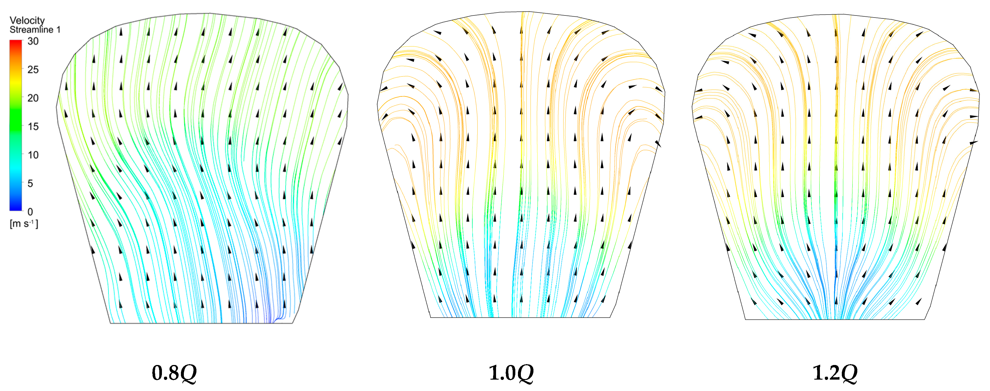
32]. In
Figure 17, the ratio of
b3/
b2 of pump A is merely 1.6, and no eddies emerged at the lower portion of the volute meridional Section 8. In
Figure 18, although the ratio of
b3/
b2 for the same pump is 2.3 under the three working conditions, the streamlines from the impeller outlet to the volute inlet are smoothly distributed. As the streamlines did not diverge abruptly, no eddies were found in the same section under different working conditions. Almost the same flowing behaviors were observed at the volute of pumps B, C. This indicates that a large
b3 giving rise to eddies at volute entrances is baseless, and no upper limit should be set for the ratio of
b3/
b2 in the volute design guidelines.
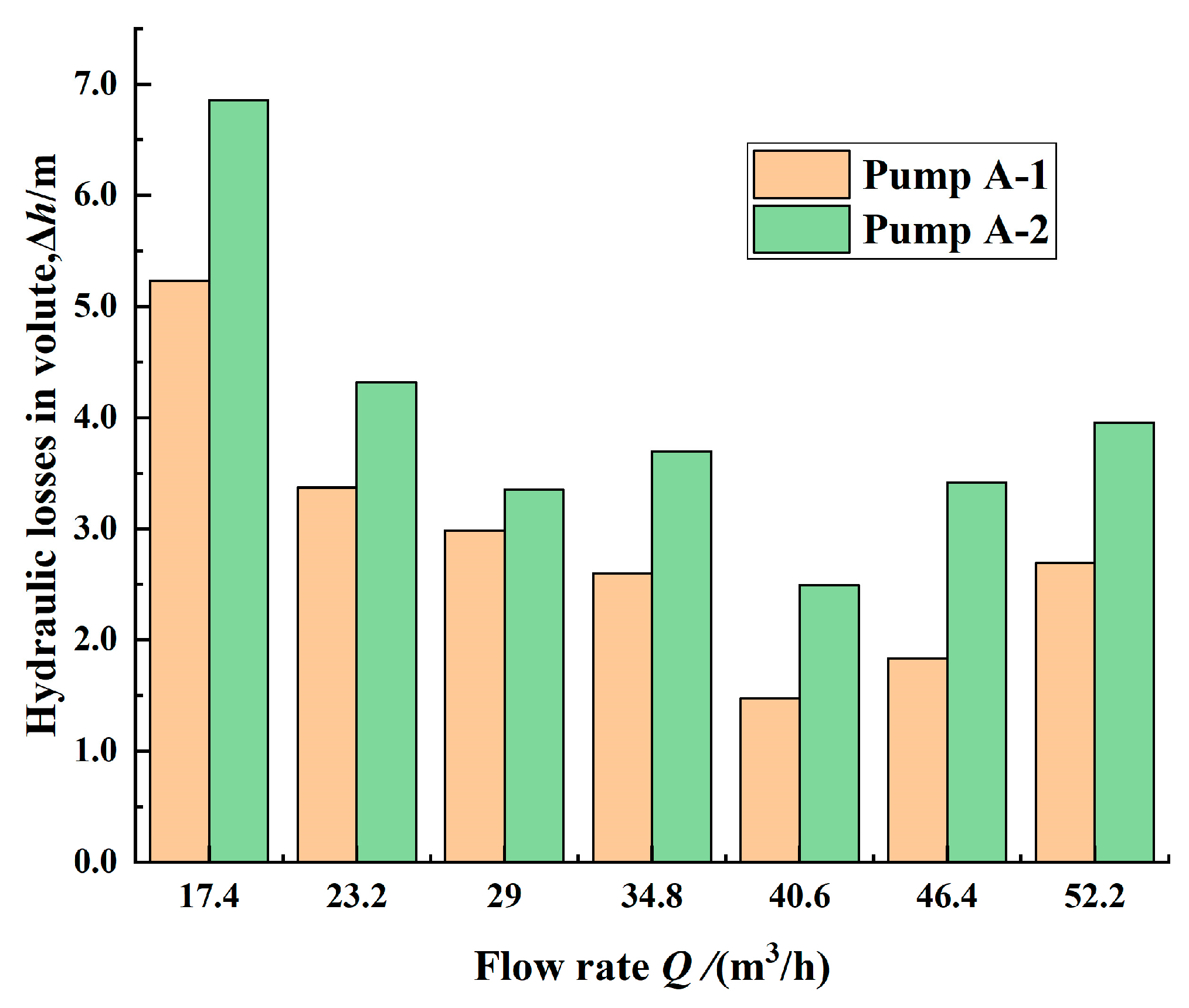
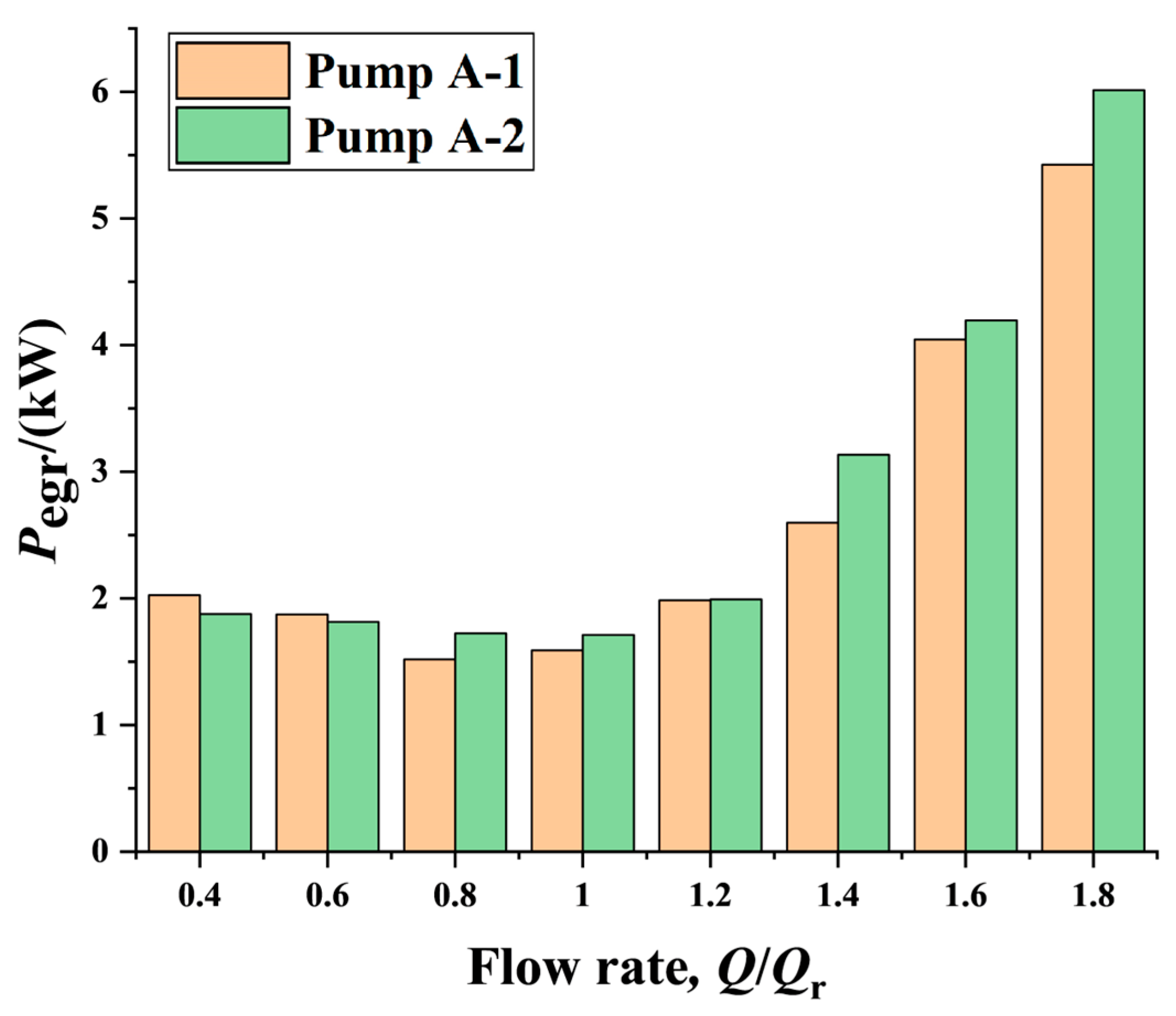
The entropy generation power (Pegr) approximately represents the summation of shock losses and friction losses generated in a pump or in a wetted part of a pump. This variable depends on the flow rates through the pump. It is evident that the smaller the value of Pegr, the lower the losses. The charts in
Figure 19 and
Figure 20 were compiled based on the simulated results of pump A.
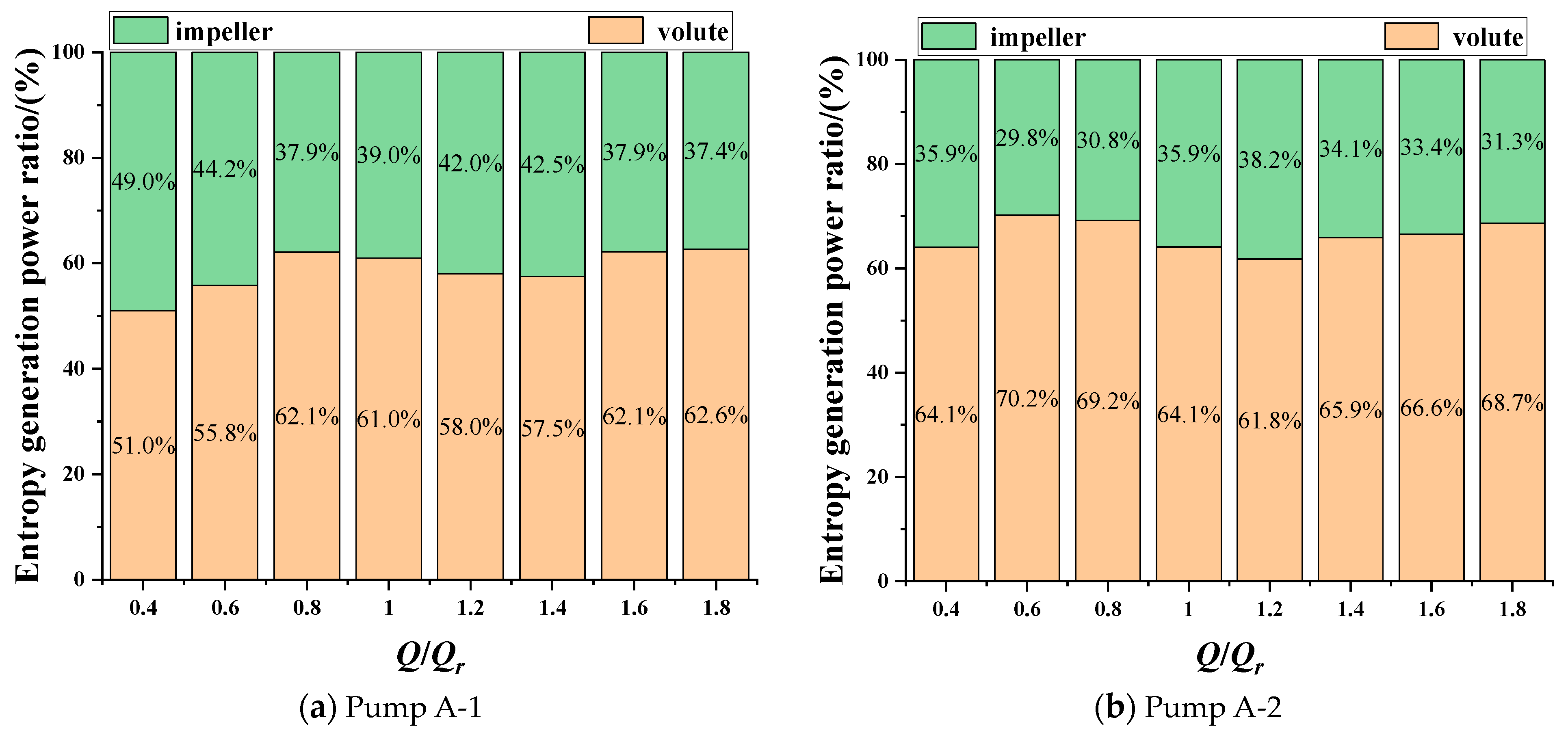
Figure 19 indicates that over the partial load region, losses in the pump decreased with increasing flow rate first and then increased with the flow rate, and under the vast majority of working conditions, the losses in the volute of pump A-1 were lower than those in the volute of pump A-2. The comparisons in
Figure 19 illustrate that under all working conditions, the ratios of losses in the volute of pump A-1 to losses in the impeller are fewer than those in the volute of pump A-2. The above-mentioned phenomena and analysis showed that the influence of the volute width
b3 on the pump performance characteristics is not decisive, and that is why width
b3 recommended in different volute design guidelines falls into a wide range. The phenomena also revealed that wetted perimeters of volute meridional cross-sections influence pump performance remarkably. In volute design practice, the guidelines in Ref. [
31] should be applied, and designers should try to reduce the wetted perimeters of the cross-sections as the design goal.


