Review

Perspectives on the Development of Technologies for Hydrogen as a Carrier of Sustainable Energy

Laboratory of Bioengineering, Institute of Chemical Engineering, Bulgarian Academy of Sciences, 1113 Sofia, Bulgaria
*
Author to whom correspondence should be addressed.
Energies 2023, 16(17), 6108; https://doi.org/10.3390/en16176108
Submission received: 19 July 2023 / Revised: 14 August 2023 / Accepted: 18 August 2023 / Published: 22 August 2023

Abstract

:
Hydrogen is a prospective energy carrier because there are practically no gaseous emissions of greenhouse gases in the atmosphere during its use as a fuel. The great benefit of hydrogen being a practically inexhaustible carbon-free fuel makes it an attractive alternative to fossil fuels. I.e., there is a circular process of energy recovery and use. Another big advantage of hydrogen as a fuel is its high energy content per unit mass compared to fossil fuels. Nowadays, hydrogen is broadly used as fuel in transport, including fuel cell applications, as a raw material in industry, and as an energy carrier for energy storage. The mass exploitation of hydrogen in energy production and industry poses some important challenges. First, there is a high price for its production compared to the price of most fossil fuels. Next, the adopted traditional methods for hydrogen production, like water splitting by electrolysis and methane reforming, lead to the additional charging of the atmosphere with carbon dioxide, which is a greenhouse gas. This fact prompts the use of renewable energy sources for electrolytic hydrogen production, like solar and wind energy, hydropower, etc. An important step in reducing the price of hydrogen as a fuel is the optimal design of supply chains for its production, distribution, and use. Another group of challenges hindering broad hydrogen utilization are storage and safety. We discuss some of the obstacles to broad hydrogen application and argue that they should be overcome by new production and storage technologies. The present review summarizes the new achievements in hydrogen application, production, and storage. The approach of optimization of supply chains for hydrogen production and distribution is considered, too.

1. Introduction

Hydrogen has the potential to be the energy of the future. It is a highly efficient, environmentally friendly, and sustainable energy carrier. From the energy-exchanging processes taking place in nature on Earth to those in space, one can see that hydrogen plays a fundamental role in all of them. It can be considered a driving force in respiration chains, the glycolytic exchange route, and the cycles of Krebs, Calvin, and Knoop, which form the basis of the biochemical process in living systems. Hydrogen is the fuel for thermonuclear fusion in stars.
Cavendish obtained pure hydrogen for the first time in 1766. This discovery had been confirmed by Lavoisier in 1783 after precise experiments. The gas was named “hydrogen”, i.e., “bearing water” in Greek. In 1839, C.F. Schönbein and W.R. Grove published their work on fuel cells and their first construction, which was used to recombine hydrogen and air oxygen, thus generating pure and efficient electricity and heat [1].
The attractiveness of hydrogen as a fuel is based on its use in a wide variety of methods for energy production. It is an excellent fuel for internal combustion engines, gas turbines, and fuel cells, providing high efficiency and practically no air pollution [2].
The energy content of hydrogen exceeds those of fossil fuels by 3–4 times and consists of 140 MJ/kg hydrogen, whereas, as a measure of the fossil fuels’ energy, oil’s equivalent capacity is 41.86 MJ/kg. Hydrogen is abundantly met in nature in the form of various chemical compounds (water in particular), which makes it attractive for different types of production [3]. Along with its use as a fuel, hydrogen is broadly used as chemical feedstock for various manufacturing processes. Ammonia production and oil refining are mostly spread ones where hydrogen is used.
The European Commission issued a final version of the “Hydrogen strategy for a climate-neutral Europe” on 8 July 2020. The philosophy of this document is in compliance with the Paris Agreement on Climate Change from 4 November 2016, which foresees the attainment of a “Carbon-neutral Europe” by 2050 [4].
Besides the advantages, hydrogen use faces some challenges. First, hydrogen production is energy-consuming, i.e., the use of carbon-containing fuels for its production must be restricted or even avoided.
The further applications of hydrogen are associated with its safe storage and operation, sometimes being non-competitive to the traditional fossil fuels. There is a threat of explosion in hydrogen storage and use. That is why many efforts have been made to overcome all these obstacles.
The present review is an attempt to discuss the present and future hydrogen applications, its methods of production given the associated challenges, and the ways to overcome them. The problems with hydrogen storage are considered, too.

2. Hydrogen Applications

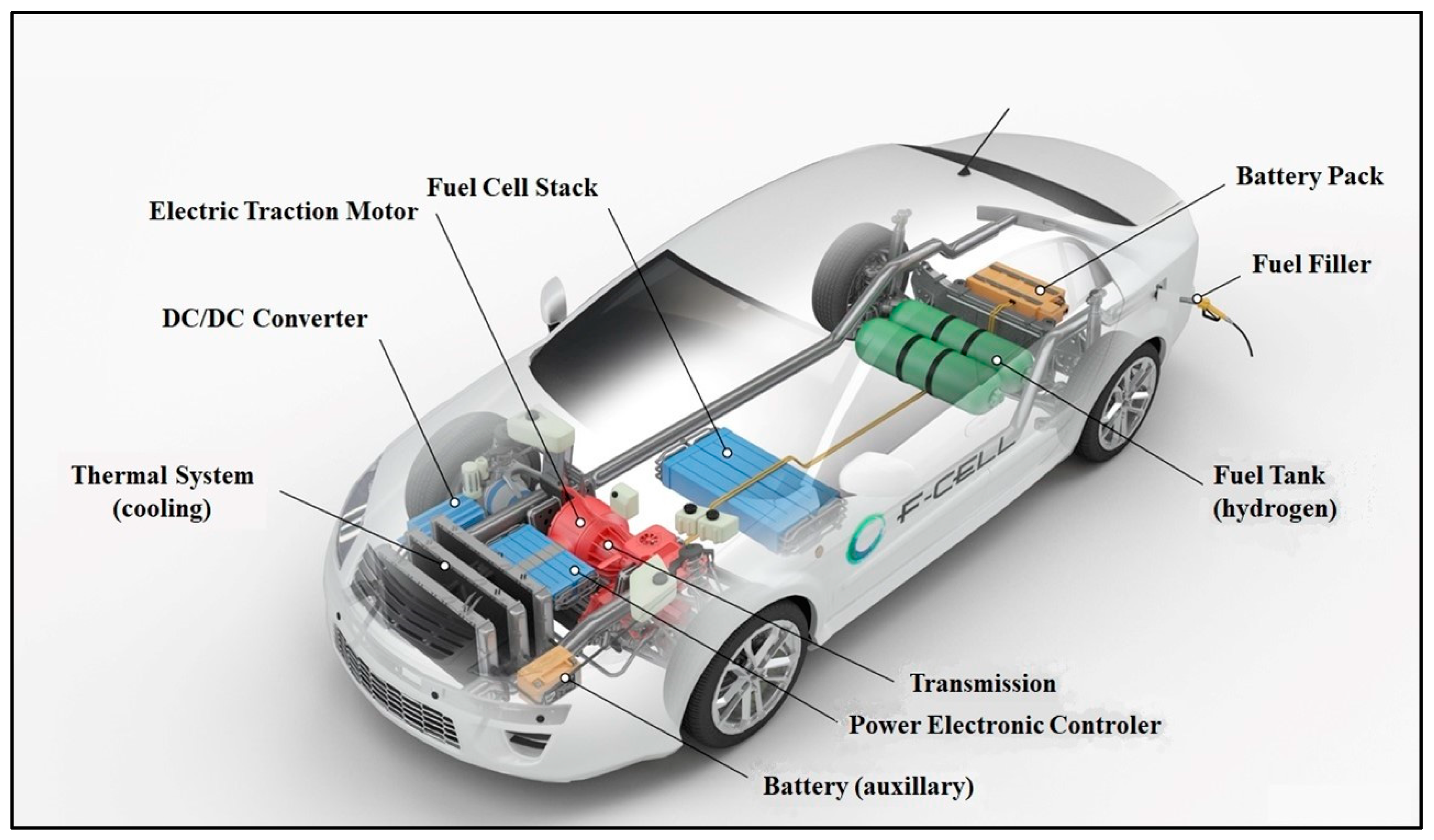
2.1. Transport Applications
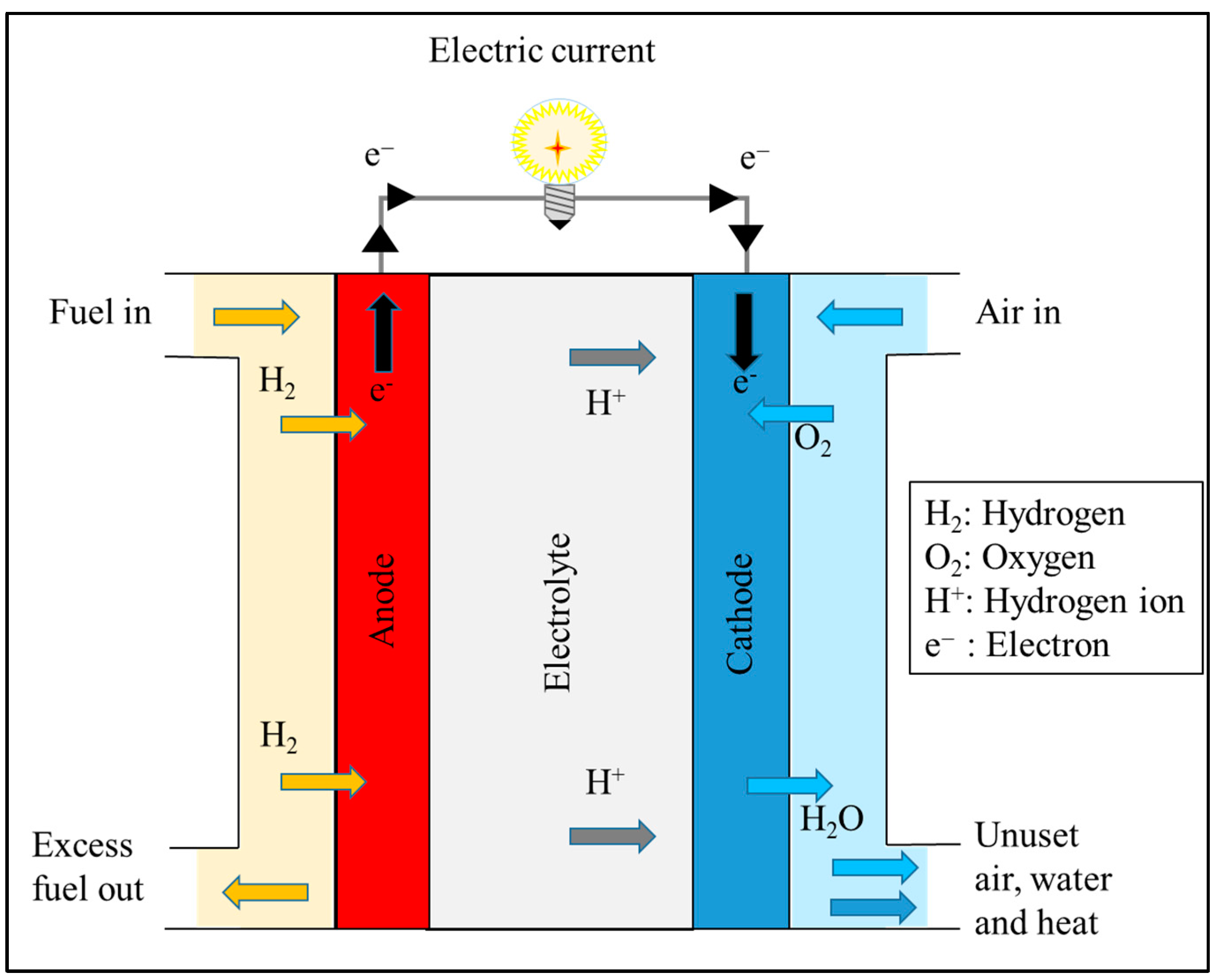
Transport is the “circulatory system” of the modern economy. The transportation of people and goods is a key factor for the sustainability and development of today’s world with different types of engines—internal combustion, electric, reactive, and steam engines. A large amount of attention is paid to the use of hydrogen as a fuel in such engines.
Engines with internal combustion (EIC) operating with fossil fuels generate about 10% of the world’s emissions of greenhouse gases [5]. This and other reasons (fuel saving and long-term exploitation) motivated scientists to improve EIC with considerable success in recent years. However, the problems with greenhouse gases and the shortage of fossil feedstock for fuel production remain.
The generation of nitrogen oxides ( N O x ) as a result of the operation of EIC is a considerable drawback for this type of engine. Nitrogen oxides are formed at high temperatures from nitrogen and oxygen in sucked air during combustion in EIC. These compounds have a negative impact on living beings, suppressing their aspiration, and are anhydrides for acids of nitrogen with a harmful impact on the environment [6]. These facts motivated the development of technology for partial or complete application of hydrogen as a fuel for this type of engine [5].
Reactive engines have broad application in modern aviation, either civil or military. There are already attempts for hydrogen-fueled reactive engines for long-distance flights [7]. The application of hydrogen in such engines can be accomplished either by compressed gas or employing hydrogen as liquid hydrogen (LH2). Hydrogen has good prospects as a fuel in aviation because it contains two important features for this purpose: very high specific energy content and carbon neutrality. The application of LH2 has a unique advantage for long-distance flights because of its high specific energy content compared to fossil fuels.
Because of these valuable characteristics, the extended application of hydrogen as a fuel must be combined with its environmentally friendly production. Together with these advantages, the application of hydrogen in aviation also has a number of drawbacks. First, compressed hydrogen must be stored at very high pressures, namely between 350 and 700 bars. Next, LH2 must be stored at very low temperatures, i.e., 20 K. In these engines, N O x is formed too, because of the high temperature of combustion [8,9,10].
Hydrogen propulsion in aircraft is considered in two ways: by direct combustion or in fuel cell equipment [9]. Both gaseous and liquid hydrogen are considered.
However, the use of hydrogen as a fuel in aviation will need new and severe safety systems for hydrogen storage and use on aircraft with new aircraft design, new infrastructure with the safety measures in the storage sites, new fuel feed systems in airports with supply chains for delivery, etc. [10,11]. These transformations will lead to an increase in the expenses per capita of passengers. But the adverse effect of greenhouse gases during the flight will be reduced by some 50 to 60% for hydrogen combustion and by 75–90% for fuel cell propulsion.
Taking into account the current status of its use, hydrogen could be first targeted as a fuel in civil aviation for short-range and medium-range routes.

2.2. Fuel Cells

The energy production by hydrogen/oxygen fuel cells is a highly efficient and environmentally friendly method for direct conversion of the chemical potential of the reagents into electricity. Generally, the hydrogen fuel cell consists of electrodes (anode and cathode) separated by a proton-exchange membrane (PEM), also referred to as an electrolyte, cf. Figure 1. The operation temperature is within 333–353 K. Hydrogen and oxygen enter the fuel cell in the anode and cathode compartment, respectively. Hydrogen is an electron donor, and oxygen is an electron acceptor. Protons are formed on the anode, passing through the membrane and reacting with oxygen at the cathode with the formation of water vapor and heat release. The electron exchange is accomplished through the external circuit as electric current due to the generated electromotive force between the electrodes [12].
The electrochemical reactions on the electrodes are the following:
Oxidation (on the anode):
2 H 2 4 H + + 4 e
Reduction (on the cathode):
O 2 + 4 H + + 4 e 2 H 2 O
Overall reaction:
2 H 2 + O 2 2 H 2 O + e l e c t r o m o t i v e   v o l t a g e + h e a t
When fuel cells are applied to electric vehicles, they are highly efficient and have low emissions in the long term, extremely low noise levels, and cheap maintenance. Nitrogen oxides are practically absent as exhaust gases. In general, the design of the fuel cell-run vehicle can be described in the following way: cf. Figure 2. The hydrogen is charged and stored in a high-pressure tank. It is supplied to a battery of fuel cells (usually called a “stack”). The generated constant electric tension is supplied to a DC/DC converter, which feeds the speed controller (power electronic controller). The driver uses the speed controller to set the necessary instant rotation frequency of the traction electrical engine [13].
Some of the earliest hydrogen fuel cells were used to provide electricity for rockets and shuttles in spacecraft. Future applications of hydrogen-driven fuel cells will likely be in automobile transport (cars and trucks), rail transport, and marine vessels. Fuel cell trains have appeared in Germany, and in the coming years, they are expected in other European countries, as well as in the U.S.A., Japan, and South Corea. Besides this, hydrogen fuel cell technology is applicable in households for local electricity production and heating in houses and industrial spaces [15]. Generally, the most prospective and already used fuel cell applications are in transport, warehouse logistics (clean trucks, forklifts, and pallet jacks), backup power generation and storage for greed balancing, unmanned aerial vehicles (UAV), etc.
In recent years, fuel cell-driven passenger vehicles have gradually been displaced by electric cars; hence, other niches for fuel cell applications have been sought, among which are large-load trucks, public buses, trains, and boats.
One of the main challenges to the broader application of hydrogen fuel cells in transport is the price and availability of the catalyst for hydrogen oxidation, namely platinum. There are many efforts and studies to replace platinum with cheaper catalysts [16], some of which use platinum-based ones doped with other metals, e.g., Co, Cr, Cu, non-noble metals or organo-metallic compounds [16]. However, the last two types still require more research.
Maybe the competition between hydrogen fuel cell-driven vehicles and electric cars will be solved by economic issues depending on the prices of catalysts for the first option and the batteries for the second, as well as the durability of the materials used in both applications.

2.3. Hydrogen Applications in Industry

Hydrogen can be an important source of energy as well as feedstock for intensive processes in industry [17]. Such industrial examples include ammonia production, direct reduction of iron ore instead of the traditional blast furnace process, and methanol production. The latter is a key feedstock for petrochemical products, biodiesel, and anti-knocking fuel additives. Methanol can be used also as an alternative fuel in diesel engines [18] or in onboard fuel cell vehicles [19].
More traditional processes, such as hydrocracking, aiming at diesel and biodiesel production with the use of hydrogen, are also used in oil and biofuel refineries. Hydrogen and captured carbon dioxide can be used to produce so-called electrofuels or e-fuels, similar to gasoline, diesel, jet fuel, etc.
The company ThyssenKrupp Steel was the first one to inject hydrogen into a blast furnace, thus replacing metallurgical coke as an additional reducing agent and hence reducing carbon dioxide release by 20% [20]. The plan was to avoid 3.5 million emissions of carbon dioxide, producing 2.5 million metric tons of iron. This success prompted the German Federal Ministry of Economic Affairs and Climate Action to promote this approach for practical application. Similar attempts are reported in India [21], Japan [22], etc. However, the inevitable carbon content in cast iron and steel must be considered.

2.4. Hydrogen as an Energy Carrier

Energy storage is required to retain the power of renewable energy sources. It facilitates the filling of the gap between demand and supply [23]. Energy storage also helps in damping energy oscillations and improving power quality and reliability. Depending on the form of energy stored, the technologies can be categorized into mechanical (hydropower), electrochemical (flow batteries and secondary batteries), chemical (hydrogen), electrical (supercapacitors), and thermal energy storage.
The straightforward way to store energy as hydrogen is to use the surplus of produced electricity by power stations for water splitting to produce hydrogen. The next technical problem is the type of hydrogen storage, depending on its further application—for chemical processes, oil refining, transport, etc.
There is one recent application of hydrogen as a large-scale fuel. It is the blending of natural gas by injection into the pipelines for gas supply. Hence, the further emissions of greenhouse gases are reduced at the same or similar energy capacity of the gaseous mixture [24]. Difference volumetric ratios are proposed, but the most reliable is 15 to 20% (vol.) hydrogen in the resulting gas [24]. Some precautions must be taken when hydrogen injection is applied. First, there is the threat of explosion, and that is why the volumetric ratio for the gases must be carefully specified. Next, there is the threat of embrittlement of the pipelines caused by hydrogen at higher concentrations accompanied by gas leakage [25].
Another indirect application of hydrogen in power production is its use as a cooling agent for heated turbines in thermal power plants. Its application for this purpose is prompted by its high heat transfer coefficient, high thermal conductivity, and high specific heat, almost equal to that of air [26].

3. Hydrogen Production
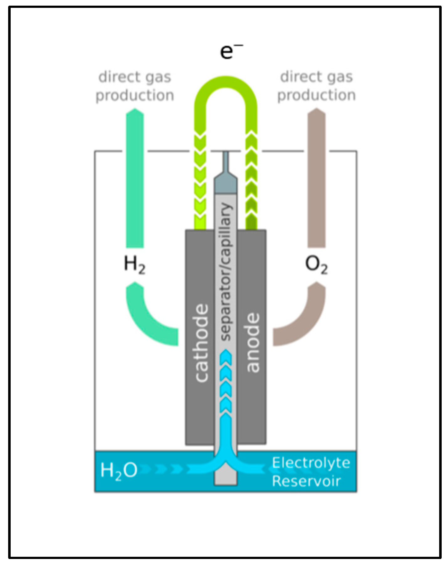
Hydrogen production is of primary importance for its further application. There are various approaches to producing hydrogen. The production of hydrogen is always associated with the use of some feedstock and energy spending. The produced hydrogen is assigned a “color” depending on the method and the harm it causes to the environment. This classification is presented in Table 1, following ref. [27].
When the electricity for water splitting is generated by a carbon-free renewable source, like wind, hydropower, or solar, the produced hydrogen is specified as “green”.
The most important methods from a practical point of view are steam and dry reforming of methane and other hydrocarbons; coal and biomass gasification; electrolysis of water; biological processes (dark and light fermentation and microbial electrolysis); photocatalysis; high-temperature electrolysis; etc. [28,29,30]. The selection of the method for hydrogen production is determined by various factors like the size of hydrogen demand (as feedstock for chemical processes, like ammonia production, and as fuel for transport), the constraints to greenhouse gas emissions, the process efficiency, etc. For example, high-temperature electrolysis and photo-fermentation have the highest and lowest energy efficiency, respectively. The carbon emissions associated with the release of carbon dioxide indicate that coal gasification has the highest global warming potential, whereas photo-fermentation has the lowest one. The photoelectrochemical process has the highest hydrogen production cost, while steam methane reforming has the lowest one. One comparison of the carbon dioxide emissions indicates that coal gasification has the highest and photo-fermentation has the lowest values [28].
The efforts toward the development of integrated systems of renewable energy sources (e.g., solar, wind, biomass, etc.) are promising. In those systems, in case the produced energy is in excess, the energy could be stored and used as hydrogen. There are mathematical models for the optimal design of supply chains, indicating the ways in which this storage can be accomplished [31]. Such models should account for the uncertainties and the necessity of integration with renewable electric power stations run with hydrogen-driven fuel cells. This would lead to improvements in sustainability and the potential to produce renewable energy continuously [32,33].

3.1. Electrolysis

About 2% of the annual production of hydrogen is produced by electrolysis [33]. Hydrogen production by splitting water by electrolysis is one of the most popular ways of doing this. However, the energy input (187–229 MJ/kg H 2 ) required to complete this process exceeds the energy of the gained hydrogen (theoretically 144 MJ/kg H 2 ). Therefore, using electricity produced from fossil fuels and charging the atmosphere with carbon dioxide for this purpose is not admissible. This is why there are some efforts attempting to minimize this adverse effect. Water electrolysis can be implemented in different ways according to its electrolyte and ion-based agent. Some examples are alkaline water electrolysis, where hydroxylic anions are transferred from the cathode space to the anode; proton exchange membrane electrolysis with proton transfer from the anode space to the cathode space; solid oxide electrolysis with O2− ion transferred through a separation membrane [34]; and anion exchange membrane electrolysis. The last is beneficial because of the low Ohmic losses and the convenience due to the absence of concentrated KOH solutions, as is in the case of alkaline electrolysis.
There is a recent study claiming to attain 95% efficiency of hydrogen production by capillary-fed electrolysis, cf. Figure 3 [35]. The electrolyte is fed continuously into the porous membrane placed between the electrodes. In this case, gas bubbles formed during water splitting do not appear, and higher electrode surfaces are available.
There are some new studies on the development of catalysts to enhance electrolysis. There are non-precious metal catalysts containing nickel and cobalt nitrides [36,37].
But, the direct way to avoid carbon dioxide release is to use electricity produced by renewable energy sources, like wind, hydropower, and solar energy, to produce green hydrogen [38]. One attractive method, However, with limited application, is to produce electricity from hydrogen sulfide, found in enormous amounts in the Black Sea. The electricity is produced in sulfide-driven fuel cells and used afterward to split water to produce hydrogen [39]. In this case, there is electricity production from a carbon-free fuel (i.e., hydrogen sulfide) generated by natural processes of waste biomass biodegradation in marine waters.
High-temperature electrolysis (HTE) is a method where steam is dissociated from H2 and O2 at high temperatures (700–1000 °C). Heating is supplied by steam injection or by independent renewable sources, like geothermal energy. In the latter case, this method becomes carbon-free and more efficient than conventional electrolysis at room temperature [40,41].
Microbial electrolysis is a new method for facilitated water splitting. There are some other efforts to minimize the energy losses during water splitting by reducing the over-potential on the cathode or by applying microbial electrolysis [42,43].
This is a way to avoid or at least remedy the high consumption of energy in hydrogen production necessary for traditional electrolysis. The method consists of anodic oxidation of reductors facilitated by exo-electrogenic bacteria (microbial electrolysis). These bacteria can be used for the direct transfer of electrons toward/from the electrode. They are strains from some well-known genera, like Enterobacter, Clostridium, Shewanella sp., Geobacter sp., and Pseudomonas [44,45]. These bacteria are usually immobilized to the operating electrode, cf. Figure 4. Organic pollutants are used as reductors instead of hydroxylic anions, as is the case in traditional electrolysis. Hence, the organic pollutants are destroyed by oxidation by microbial catalysis, and the energy of these reactions is used for the production of hydrogen. That is why the microbial electrolysis cell attains voltages within 0.6 and 1 V instead of 2.3 V for the traditional electrolysis cell [44,46]. Some data for microbial electrolysis with different substrates are shown in Table 2.

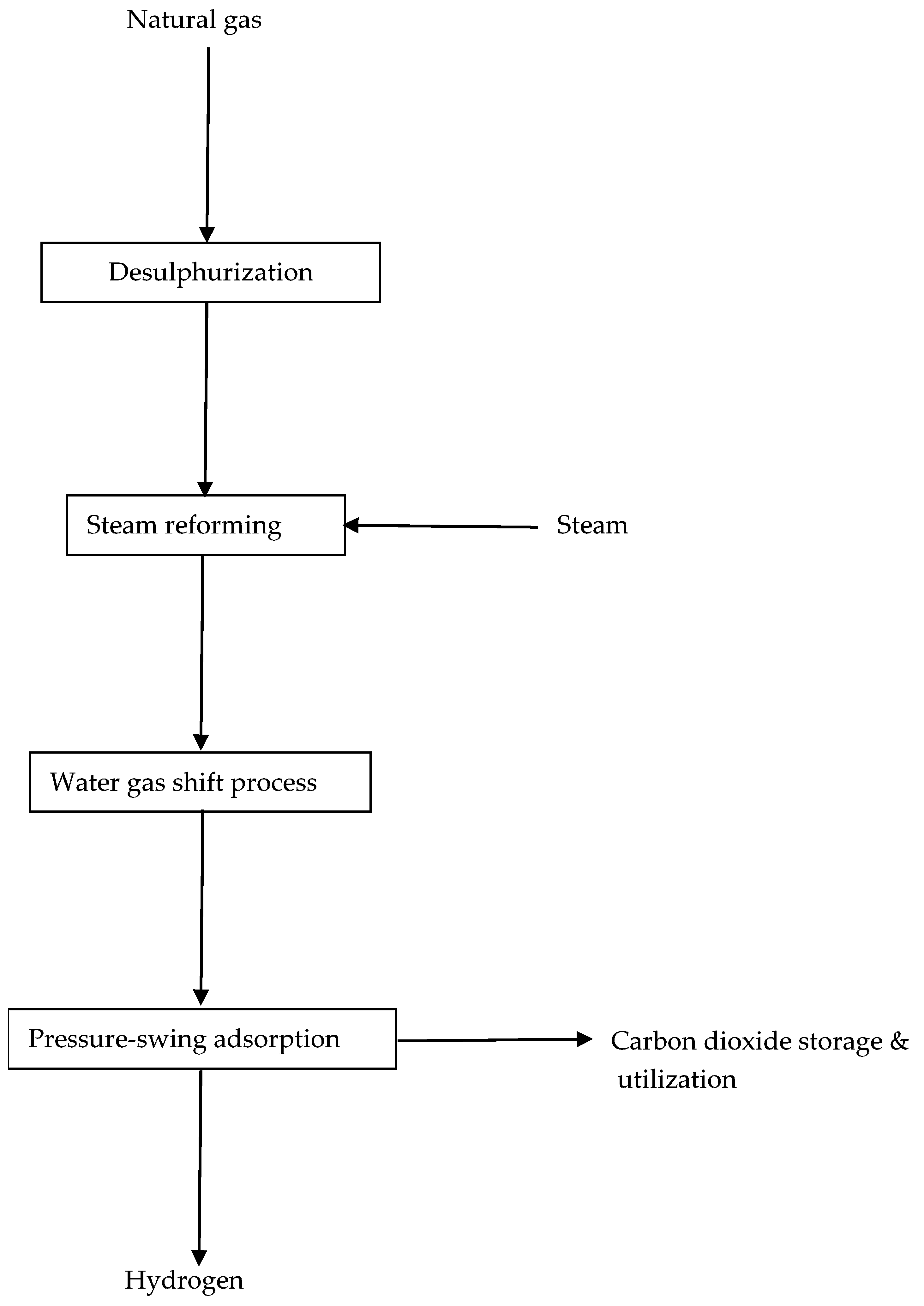
3.2. Natural Gas Processing

The annual hydrogen production from natural gas by steam reforming consists of 48% of the total produced amount [28]. Steam reforming is the reaction of conversion of methane to a mixture of carbon monoxide and hydrogen:
C H 4 + H 2 O h e a t C O + 3 H 2
The process is endothermic, and it runs at temperatures between 700 and 1000 °C at high pressure (7 to 25 bar). The next step is the water–gas shift reaction, leading to carbon dioxide and additional amounts of hydrogen:
C O + H 2 O C O 2 + H 2
The energy efficiency of these processes is 64% [47]. It is evident, however, that carbon dioxide is the inevitable final product. The main pollution by carbon dioxide comes from the energy used for heating the reaction mixtures. Nevertheless, this process is mostly used for the production of hydrogen for industrial purposes, e.g., for ammonia production. There are recent efforts to avoid carbon dioxide release, leading catalytic processes to the formation of elemental carbon (cf. the so-called turquoise hydrogen); they are the papers of Banu and Bicer [48] and Muto et al. [49]. Metals of the iron group, as well as some noble metals, are tested as catalysts. However, the accumulation of carbon soots can block the catalyst’s active centers. There are also attempts to introduce dry reforming integrated with the capture of carbon [50]. There are also works on the optimization of biogas-reforming conditions considering carbon formation as a by-product [51]. Levikhin and Boryaev [52] propose the production of syngas from mixtures of hydrocarbons by partial oxidation with a consequent water-shift reaction to produce an additional amount of hydrogen. The problem is the high temperature (1300–1500 °C).
A principal scheme of the steam reforming of natural gas for hydrogen production is shown in Figure 5.

3.3. Photoelectrolysis

In photoelectrochemical (PEC) water splitting, hydrogen is produced from water using sunlight and specialized photoelectrochemical materials, which use light energy to directly dissociate water molecules into hydrogen and oxygen. The water-splitting reaction can be written as follows [53].
2 H 2 O + h v = 2 H 2 + O 2 , G   =   237   k J / m o l e
This reaction is energy-consuming, but it is more beneficial than the traditional electrolysis of water. The recovered energy as produced hydrogen is 286 KJ/mol, i.e., in the PEC case, the balance is positive. The main challenge consists of the selection of appropriate photocatalysts to split water into hydrogen and oxygen [53,54].

3.4. Renewables

The benefit of these substrates consists of the low carbon dioxide release or even the lack of it. Examples of such energy sources are hydropower [55], wind [56], and solar energy. These three sources of carbon-free energy are well distributed and broadly applied in practice [57]. Shah et al. [58] propose an integrated scheme for hydrogen production using geothermal sources for thermo-electrolysis with water pre-heating. Biofuels, like biogas and ethanol, are also included in this group, because they are produced from renewable biomass grown in the present nature. Biogas consisting of methane and carbon dioxide can be converted into syngas by dry reforming, as follows [59]:
C H 4 + C O 2 = C O + 2 H 2
There is a way to produce hydrogen with low energy consumption. It is the method of producing hydrogen directly by microbial processes [60]. There are two types of bio-hydrogen production: photo-fermentation, enhanced by light,
6 H 2 O + 6 C O 2 h ν C 6 H 12 O 6 + 6 O 2
and consequent conversion into hydrogen and carbon dioxide,
C 6 H 12 O 6 + 12 H 2 O h ν 6 H 2 + 6 C O 2
Another one is dark fermentation. It is an anaerobic process which converts sugars (e.g., hexoses) into fatty acids and hydrogen. It is shown below:
C 6 H 12 O 6 + 2 H 2 O = C H 3 C O O H + 4 H 2 + 2 C O 2
C 6 H 12 O 6 + 2 H 2 O = C H 3 C H 2 C H 2 C O O H + 2 H 2 + 2 C O 2
The first of these stoichiometric equations, Equation (10), shows that 1 mole of glucose can be converted into no more than 4 moles of hydrogen. The competitive reaction in Equation (11) will lead to a lower yield of hydrogen. There are also combinations of dark and photo-fermentation leading to more complete sugar destruction and hydrogen production and higher molar yields, as follows:
2 C H 3 C O O H + 2 H 2 O + h ν = 8 H 2 + 4 C O 2
A comparison of the energy consumption and the efficiencies of different methods of hydrogen production is shown in Table 3.
The energy used for this two-stage fermentation process (0.97 kWh/Nm3) is over three times less than the energy of the produced hydrogen (3.55 kWh/Nm3). Dark and light fermentations are energetically beneficial processes compared to traditional electrolysis. Bio-hydrogen production utilizes various waste organic products, combining energy production with waste treatment [61]. Bio-hydrogen does not emit carbon dioxide and yields water as waste, which is a substrate for further production. Bio-hydrogen applications are not restricted to transport only. It can also be applied as a raw material in chemical products, like ammonia, urea, methanol, etc. [62,63].
However, the hydrogen production rates are of the order of magnitude~0.2 ÷ 0.6 L/L/h (2.18 L/L/h at most [63]), and the bioprocess efficiencies are too low compared to the traditional steam reforming, cf. Table 3.
A flowsheet of biohydrogen production coupled with biogas production is shown in Figure 6.
Liquid methanol can be used as a hydrogen carrier. It has high energy density, and it is also environmentally friendly. Methanol has a high hydrogen-to-carbon ratio, is liquid under ambient conditions, and is convenient for storage and transportation [64]. One method for methanol-to-hydrogen conversion is steam reforming of methanol to produce hydrogen with a high yield (99 g H2 per liter methanol) and low carbon monoxide content [57], cf. Equation (13),
C H 3 O H + H 2 O = C O 2 + 3 H 2    H   =   49   k J / m o l
This method, however, requires energy input. Another method for conversion of methanol to hydrogen is partial oxidation of methanol by exothermal reaction [65], cf. Equation (14):
2 C H 3 O H + O 2 = 2 C O 2 + 4 H 2    H   =   192   k J / m o l
However, it has lower yields compared to steam reforming. There is also a combination of these two processes known as autothermal methanol reforming, cf. ref. [66]. The main problem that remains for this method is the necessity of energy supply and the inevitable final release of carbon dioxide. A comparison of these three options is shown in Table 4.
Table 4. Comparison of the methods for hydrogen release from methanol, after ref. [64].
MethodChemical ReactionsAdvantagesDrawbacks
Methanol steam reformingCH3OH + H2O = CO2 + H2High hydrogen yield, low CO content, and low operating temperaturesRequires external energy supply
Partial oxidation of methanolCH3OH + 1/2O2 = CO2 + 2H2Fast start-up and response; no thermal managementLow hydrogen yield, high temperatures, and high CO content
Autothermal methanol reformingCH3OH + αO2 +(1 − 2α)H2O = CO2 +(3 − 2α)H2Simplified thermal management, low temperatures, and fast start-upLow hydrogen yield; requires control to balance exothermic and endothermic processes
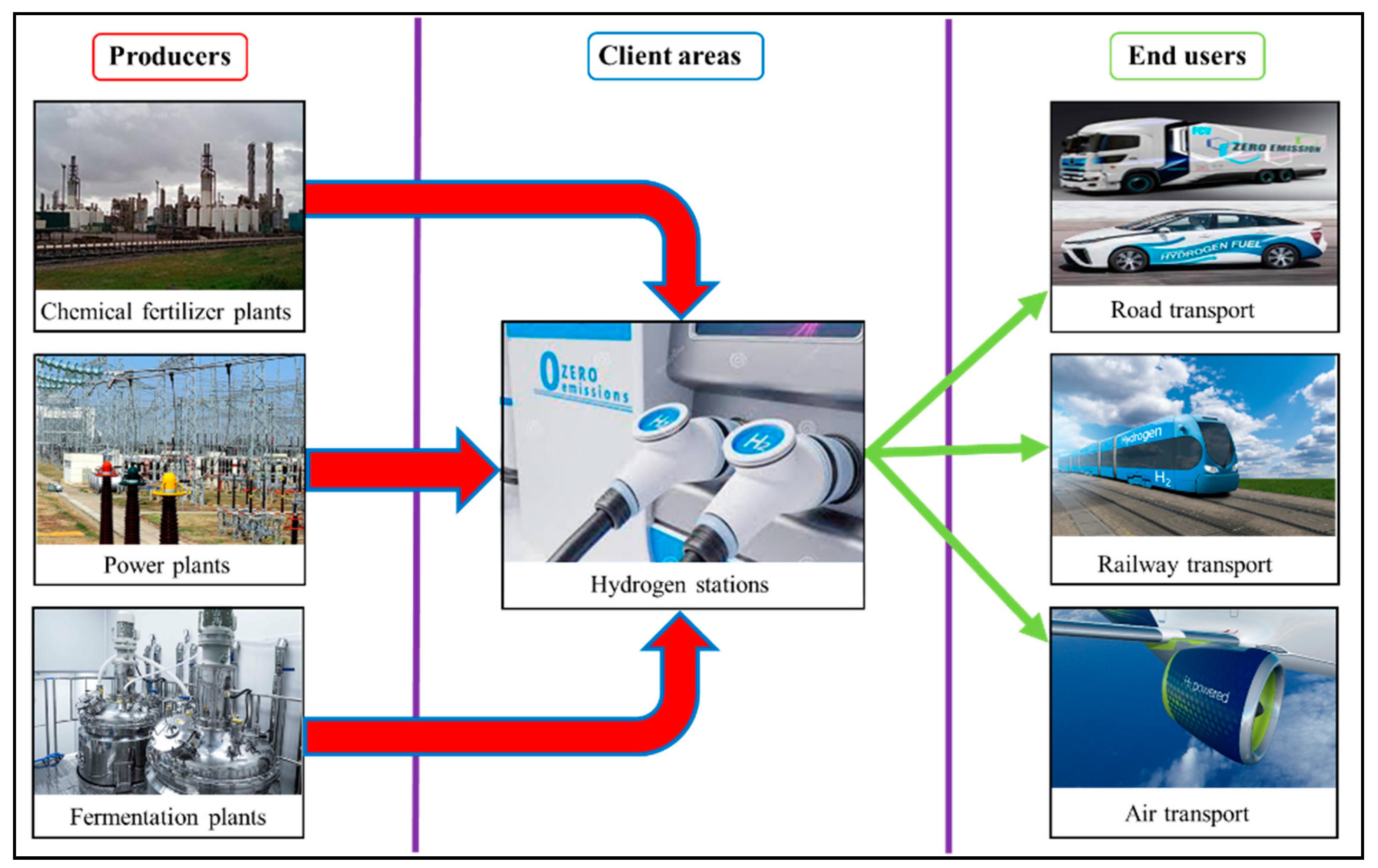
Hydrogen is an inevitable feedstock for ammonia production, according to the traditional Haber–Bosch process. There is an opportunity to use ammonia as a substance for hydrogen storage [67]. It has a high hydrogen density (17.8 wt%), along with several advantages over the direct use of hydrogen for long-distance shipping, meeting around 45% of global shipping fuel demand. Ammonia is also co-fired in existing coal power plants to reduce CO2 emissions [68]. However, significant energy input is required to release hydrogen from ammonia, and new catalysts for ammonia decomposition are sought. Other restrictions include safety and toxicity threats, as well as the vulnerability of polymer electrolyte membrane fuel cells toward even trace levels of ammonia.
A principal flowsheet for the utilization of ammonia as a hydrogen storage tool is shown in Figure 7.

4. Supply Chains

Besides the exclusive advantages of hydrogen as an energy source, its price is a serious drawback for its mass application. An irrefutable factor that can influence price formation is the optimization of its supply chains [68]. The composition of an optimal supply chain requires a precise analysis of the fuel life cycle (LCA) for each particular stage along the chain, cf. Figure 8. Here, only the traditional sources of hydrogen are considered. Other sources, like biomass, methanol, ammonia, etc., must be treated additionally. Afterward, the most impactful factors on each different step of the life cycle need to be specified, the constraints must be defined, and the uncertainties have to be foreseen for a specified period of time [69].
At the beginning of the model description, it is necessary to introduce constant parameters known by presumption. Afterward, the parameters to be optimized, i.e., the variables, have to be specified. The mathematical model has to be hierarchically described by the target function and the constraints. For this purpose, the input parameters, the variable multiplicities and sub-multiplicities, as well as the indices, must be specified, starting with the time ranges in the horizon of planning t = 0 , 1 , 2 , , T [69]. In order to meet the sustainability condition, in the mathematical analysis, we adopt the criteria of environmental advisability, economic efficiency, and social orientation at the same time. The combination of these three criteria defines the domain of sustainability, cf. Figure 9 [75]. This domain of sustainability proposes an integrated hydrogen supply chain (IHSC). Here, we present an example of the optimization of the supply chain for hydrogen as a fuel, focusing on the construction of charging stations. We argue that it is expedient for the utilities for hydrogen production to be built on the territory of existing enterprises, e.g., chemical and fertilizer plants associated with hydrogen production from natural gas, power stations where facilities for electrolysis of water can be constructed for the production of hydrogen by fermentation as a future prospect. This aspect of planning is up-to-date because of the fact that there are many countries with insufficiently developed infrastructure or that even lack such infrastructure. These facts hinder the application of such a hydrogen strategy in those regions [76].
The optimization problem is essentially a multi-target one. In order to simplify it, we render it to a single target one by constraining two of the criteria and searching for the optimum solution with respect to the third one. Hence, the problem will be solved with respect to each of the criteria, and the compromise will be found in the domain of the optimal values. For this purpose, we consider the IHSC as an aggregate of the following steps, cf. Figure 10.
  • The step of hydrogen production, consisting of different sub-steps depending on the used feedstock;
  • The step of hydrogen transportation, related to its supply to the zones of clients;
  • The step of the final use of hydrogen, where it is plugged into the vehicle tanks for useful exploitation.

4.1. General Impact on Environment TEIt, [ k g C O 2 e q /d]

The environmental criterion is introduced to minimize the total annual amount of greenhouse gases generated by the IHSC during its whole life cycle. Such gases are carbon dioxide C O 2 , methane C H 4 , and nitrous oxide N 2 O , classified by the equivalent carbon dioxide emissions k g C O 2 e q / y as a unit indicator. Considering the greenhouse potential of C O 2 as the unit, its value for methane is 25 and its value for N2O is 298 [76].
T E I t = E L H t + E L D t + E T T t + E S W t + E A P P t , t
where
  • T E I t Total environmental impact due to the IHSC operation during the whole life cycle k g C O 2 e q / d .
  • E L H t Total greenhouse emissions from hydrogen production k g C O 2 e q / d .
  • E L D t Total greenhouse emissions from diesel production k g C O 2 e q / d .
  • ETTt Environmental impact from the transportation of feedstocks and final product, including diesel k g C O 2 e q / d .
  • E S W t Emissions released during waste utilization, resulting from hydrogen production during each time period t T k g C O 2 e q / d .
  • E A P P t Emissions resulting from the use of hydrogen as fuel k g C O 2 e q / d .

4.2. Total Costs THCt, [$/y]

This economic criterion reflects the costs for the maintenance of each initiative (i.e., industrial enterprises and charging stations), including the total investment costs for hydrogen production facilities, hydrogen charging stations, and IHSC operation. The relationship representing this price for each time period t T is as follows:
T H C t = T I C t + T P C t + T P W t + T T C t + T T A X B t + T I H S C t + T O E C t T L t T A t , t
where
  • T H C t Total annual costs for the IHSC [ $ / y ] .
  • T I C T Total investment costs for production capacity of the IHSC compared to the operation and redemption of the facility per year [ $ / y ] .
  • T P C t Operational costs for hydrogen production [ $ / y ] .
  • T P W t Operational costs for utilization of waste from hydrogen production [ $ / y ] .
  • T I H S C t Total investment costs for commercial capacity of the IHSC compared to the operation and redemption of the hydrogen facility per year [ $ / y ] .
  • T O E C t Operational costs at the final sales of hydrogen [ $ / y ] .
  • T T C t Total transportation costs in the IHSC [ $ / y ] .
  • T T A X B t Carbon tax, charged according to the total sum of generated energy at the work of IHSC [ $ / y ] .
  • T L t Governmental incentives for the production and use of hydrogen [ $ / y ] .
  • T A t Total value of the by-products [ $ / y ] .

4.3. Social Estimate for IHSC [Number of Jobs/y]

The social estimate of the IHSC operation tries to predict the jobs J t to be created as an outcome of the IHSC during its operation.
J o b t = N J 1 t + L T t N J 12 t + N J 2 t + L T t N J 21 t ,   t
where
  • N J 1 t Number of jobs created during construction of the hydrogen facility.
  • L T t N J 12 t Number of jobs created during the operation of the hydrogen facility.
  • N J 2 t Number of jobs created during the installment of the charging stations.
  • L T t N J 21 t Number of jobs created during operation of the charging stations.

4.4. Input Data for the Supply Chain

The real application of the model for the optimal design of a supply chain for a certain territory of a state, region, or municipality requires the dissemination of input data specific to the region. This data must be tailored to the aims of the state or the region for the current period. All introduced criteria (environmental, economic, and social) should be considered. The data must correspond to the time scale of the optimization problem. Such input data could be
  • The territorial distribution and hydrogen demand for transport;
  • The potential localization of the enterprises for hydrogen production in the studied region;
  • The potential feedstock for the region;
  • Data about the emissions for each type of hydrogen production;
  • Data about the operational costs for each type of hydrogen manufacturing;
  • The potential localization of the charging stations.
Other data include conversion factors of feedstock and energy to hydrogen (being specific to each production technology), costs and capacity of the facilities for hydrogen production, and operational costs for hydrogen production.
There is also a necessity for data about the emission coefficients of diesel and hydrogen, their energy equivalents, average density, and price. Data about the transport costs and the emission factors for feedstock and hydrogen, as well as data about the real distance for supply between the producers and the regional hydrogen consumers, must be included as well.

5. Hydrogen Storage

Hydrogen storage is a key issue for the reliability of further hydrogen applications. The difficulty with such storage arises from the properties of hydrogen: it has very large permeability through solid obstacles like metals, which makes them brittle, thus potentially damaging the pipelines and storage tanks. On the other hand, hydrogen is highly explosive and, therefore, careless handling may cause serious accidents. That is why safe hydrogen storage is of great importance for further practical applications. The hydrogen storage market is segmented by applications into stationary power, portable power, and transportation to run automobiles, aerospace, and its use throughout the hydrogen supply chains. It can also be transported from the point of production to the point of use. Compressed hydrogen storage is beneficial for fuel purposes because, in this form, it can be stored in a smaller space while retaining its energy efficiency [77,78,79]. However, this method is volumetrically and gravimetrically inefficient [80,81]. Besides its traditional storage in high-pressure cylinders, there is also storage of hydrogen in a liquefied state. It requires cryogenic conditions, which makes this method energetically unsuitable [82].
The existing commercially available hydrogen storage technologies are based on bulky and costly pressure vessels. These pressure vessels vary from steel cylinders to composite-wrapped cylinders with metallic or polymer liners. These cylinders are safe with a burst pressure higher than 3 × 700 bars. The vessel has low permeability with a hydrogen leak rate below 0.05 g/hr/kg H2 when stored [83].
There have been many efforts to store hydrogen safely under solid-state conditions by physical adsorption and chemo-sorption on suitable carriers [84]. There are several requirements for the reliability of hydrogen solid carriers: high storage capacity, low specific mass, and easy hydrogen release after heating. Hydrogen could be competitive with fossil fuels (like gasoline) if the carrier has comparable mass density to gasoline. Last but not least is the price of the carrier and its toxicity. There has been a trend in the last 5 decades of researchers who have been trying to develop materials with suitable chemical properties (adsorption capacity and strong bonds of hydrogen molecules with the active centers of the adsorbents) alongside physical properties (like low specific mass). These properties have to enable the accumulation and storage of hydrogen at ambient temperatures and reasonably low pressures.
As hydrogen carriers, different metals and alloys were tested. Examples include metals, such as magnesium, intermetallic compounds forming hydrides (e.g., L a N i 5 and F e T i ), nickel and its alloys [85], aluminum and lithium forming hydrides, like N a A l H 4 [86] and L i A l H 4 [85], boranes such as L i B H 4 [87], M g ( B H 4 ) 2 [88], and ammonia borane ( N H 3 B H 3 ) [89], etc. The latter have sufficient adsorption capacity to attain 9 wt.% hydrogen. The compound L i B H 4 has a very high hydrogen adsorption density of 10% (wt.), but it requires a high desorption temperature, i.e., greater than 470 °C [85]. There is a new study on the properties of a surface boron–carbon compound, namely BC7, with very high adsorption capacity, i.e., 10.4% (wt.) [90]. M g 2 N i H 4 is attractive as a promising hydrogen storing material as it has a relatively high capacity, low cost, and light weight [91,92].
Magnesium hydride, M g H 2 , combines a high H 2 capacity of 7.7 wt% with the benefit of the low cost of the abundantly available magnesium [93,94] and has good reversibility [95,96]. The main disadvantages of M g H 2 for hydrogen storage is the high temperature of hydrogen discharge, slow desorption kinetics, and high reactivity toward air and oxygen [97,98]. A thermodynamic study of the magnesium hydride system has shown that the operating temperature was too high for practical onboard applications, i.e., 300 °C at 1 bar H 2 [94,99,100]. There are also new approaches and associated materials, like carbon nanotubes (CNTs) [101], metal–organic frameworks (MOFs) [102], fullerenes, graphenes, etc. MOFs can be used as proton exchange membranes to convert the stored hydrogen into electricity in fuel cell applications [102]. Another approach for hydrogen storage developed recently is electro-sorption, like some electro-conducting polymers [103]. Such polymers are poly-aniline [104,105], poly-thiophene [105], and poly-pyrrole [104,106]. The method consists of hydrogen adsorption on electrically conductive sorbents stimulated by a constant electric field [107]. The main advantage of these materials is their low density. However, an obstacle is the extremely low adsorption temperature (about 77 K), cf. Germain et al. [108].
Cryogenic conditions enable the storage of hydrogen in the liquid phase below its boiling point, i.e., −252.8 °C at a pressure of 1 bar. However, at such low temperatures, material embrittlement or embrittlement caused by hydrogen may take place. Special alloys are necessary to resist this adverse effect. Another challenge for this application is the necessary super-insulation to maintain such low temperatures.
As mentioned above, ammonia and methanol are promising compounds to store hydrogen with further release when necessary. Data show that ammonia can be stored under milder conditions compared to hydrogen. For example, ammonia stored at a pressure of 1 MPa and 25 °C has 1.5 times higher hydrogen density compared to stored liquid hydrogen at 0.1 MPa and −253 °C. Therefore, ammonia can be used as an efficient storage method with subsequent catalytic decomposition and hydrogen release [106].

6. Perspectives for Hydrogen-Based Economy

Economy development needs two main substantial tools: energy and raw materials. Hydrogen successfully meets these two conditions. Starting with a demand of about 40 million tons of hydrogen in 1980, it reached 127 million tons in 2018.
From an energetic and environmental point of view, hydrogen is beneficial as an alternative to fossil fuels because it contains much more energy per unit mass and does not release greenhouse gases after use. The most appropriate application of hydrogen in transport is its use in fuel cells, particularly for bulk transport, trains, boats, and airplanes.
Hydrogen is also used as an alternative to methane as a fuel, and it is injected into pipelines for the transport of natural gas to reduce carbon emissions after combustion.
A separate application of hydrogen is as a cooling agent for power turbines in thermal power stations.
In addition to environmental sustainability issues, developed countries suffering from a shortage of energy, such as Japan and South Korea, are also attaining energy security by applying hydrogen or hydrogen carriers, such as ammonia and methylcyclohexane. Hence, it is suitable to solve the problem of energy dependence with hydrogen.
The main demands for hydrogen in industry are for ammonia production and oil refining. There are some new applications of hydrogen in industry. Along with its traditional use for ammonia production, nowadays, hydrogen is foreseen to replace, at least partially, coke in blast furnace processes in order to reduce carbon dioxide emissions. Some other industrial applications are production of methanol and oil refining by hydrocracking. Hydrogen can also be processed with CO₂ to yield synthetic methane or syngas (hydrogen/CO/CO₂ mixture). It is applied on an industrial scale in South Africa with coal as a feedstock. The distribution of industrial areas where hydrogen was applied for three years in the past is shown in Figure 11. Obviously, oil refining and ammonia production are the most spread applications, whereas the demands for methanol and steel production are still much lower.
The higher prices of hydrogen compared to the prices of fossil fuels still do not permit its broader application as a fuel. As mentioned above, the main hindrance to broader hydrogen application is the costly production and the high energy demand for this purpose. The cheaper process is the steam reforming of methane, but this is accompanied by charging the atmosphere with carbon dioxide. The next method for hydrogen production is steam reforming of coal and oil with hydrogen as a product, which is called “black” or “brown” hydrogen production. Electrolysis is the next important method, which has energy consumption higher than the energy yielded by the produced hydrogen. The efforts in this direction are to enhance the process efficiency of new cell constructions, produce new efficient and cheap catalysts, and use carbon-free and cheap renewable energy sources.
The International Energy Agency foresees that the cost of producing hydrogen from renewable electricity could fall 30% by 2030 as a result of decreasing costs of renewables.

7. Discussion

Hydrogen is a prospective energy carrier because of the fact that during its use as a fuel, there are practically no gaseous emissions of greenhouse gases to the atmosphere. The product of combustion is simply water, which is a source of its production, i.e., there is a circular process of energy recovery and use. This is the main advantage of hydrogen as a fuel.
Another big advantage of hydrogen as a fuel is its high energy content per unit mass compared to the fossil fuels.
Besides its use as a fuel, hydrogen is broadly used in the chemical industry, for example, in the synthesis of ammonia. The mass exploitation of hydrogen in energy production, industry, and as a fuel poses some important challenges.
First, its production price per unit of utilized energy is twice as high as the price of production of fossil fuels. Production and delivery costs must be decreased. Therefore, new efficient technologies for its production are required.
Next, the adopted traditional methods for hydrogen production, like water splitting by electrolysis and methane reforming, lead to charging the atmosphere with carbon dioxide, which is a greenhouse gas. A better approach would be to use carbon-free energy sources for electrolysis.
Fermentative methods for hydrogen production seem to be a good carbon-free alternative, but they still have low efficiency compared to traditional methods like steam reforming of natural gas. An advantage of bio-hydrogen production by fermentation is the utilization of wastewater containing residual organic compounds as substrates. That is why there will be a double benefit: simultaneous production of hydrogen accompanied by wastewater treatment. An important direction to improve the cost of hydrogen as a fuel is to focus on optimizing the design of supply chains for its production, distribution, and use.
Another group of challenges hindering the broad hydrogen utilization are storage and safety operations. Explosive gases like compressed hydrogen require safe storage and operation. However, the high specific mass of the available alloy hydrogen carriers compared to those of gasoline and diesel makes them non-competitive. Other obstacles to efficient hydrogen use as a fuel in transport are the extremely low storage temperatures to be maintained and the high fragility of the container materials at these low temperatures and high pressures. That is why the conversion of hydrogen into safe carriers with low densities at ambient temperatures, like methanol and ammonia, is up-to-date.
Building new infrastructure for hydrogen production, distribution, and supply is inevitable and must take into account its properties in the safety measures and storage methods and facilities.
The big benefits of hydrogen as a practically inexhaustible carbon-free fuel make it an attractive alternative to fossil fuels. That is why the discussed obstacles, such as high prices and energy-consuming processes, carbon-free production, safe and cheap storage, and operation for its broad application, should be overcome by new technologies for its production, storage, and utilization. All of them involve new, cheap, and efficient catalysts and materials for fuel cell applications for efficient electrolysis and cheap batteries for energy storage.

Author Contributions

Conceptualization, V.B.; methodology, E.G.; data curation, E.G. and V.B.; writing—original draft preparation, E.G.; writing and editing, V.B.; project administration, V.B.; funding acquisition, V.B. All authors have read and agreed to the published version of the manuscript.

Funding

This study is supported by the project BG05M2OP001-1.002-0014 “Center of competence HITMOBIL—Technologies and systems for generation, storage and consumption of clean energy”, funded by “Operational Programme for Smart Growth”, 2014–2020 co-funded by the EU from European Regional Development Fund.

Institutional Review Board Statement

Not applicable.

Informed Consent Statement

Not applicable.

Data Availability Statement

Not applicable.

Acknowledgments

The authors appreciate the help of E. Kirilova from the same institute for the useful discussion on the supply chain methodology in the considered case.

Conflicts of Interest

The authors declare no conflict of interest.

References

  1. Winter, C.-J. Into the hydrogen energy economy—Milestones. Int. J. Hydrogen Energy 2005, 30, 681–685. [Google Scholar] [CrossRef]
  2. Verhelst, S.; Wallner, T. Hydrogen-fueled internal combustion engines. Prog. Energy Combust. Sci. 2009, 35, 490–527. [Google Scholar] [CrossRef]
  3. Xu, X.; Zhou, Q.; Yu, D. The future of hydrogen energy: Bio-hydrogen production technology. Int. J. Hydrogen Energy 2022, 47, 33677–33698. [Google Scholar] [CrossRef]
  4. European Commission. A Hydrogen Strategy for a Climate-Neutral Europe, Communication from the Commission to the European Parliament, the Council, the European Economic and Social Committee and the Committee of the Regions; COM(2020) 301 final; European Commission: Brussels, Belgium, 2020. [Google Scholar]
  5. Reitz, R.D.; Ogawa, H.; Payri, R.; Fansler, T.; Kokjohn, S.; Moriyoshi, Y.; Agarwal, A.; Arcoumanis, D.; Assanis, D.; Bae, C.; et al. IJER editorial: The future of the internal combustion engine. Int. J. Engine Res. 2020, 21, 3–10. [Google Scholar] [CrossRef]
  6. Hocking, M.B. Fermentation processes. In Modern Chemical Technology and Emission Control; Springer: Berlin/Heidelberg, Germany, 1985; pp. 338–377. [Google Scholar] [CrossRef]
  7. Ranasinghe, K.; Guan, K.; Gardi, A.; Sabatini, R. Review of advanced low-emission technologies for sustainable aviation. Energy 2019, 188, 115945. [Google Scholar] [CrossRef]
  8. Saias, C.A.; Roumeliotis, I.; Goulos, I.; Pachidis, V.; Bacic, M. Assessment of hydrogen fuel for rotorcraft applications. Int. J. Hydrogen Energy 2022, 47, 32655–32668. [Google Scholar] [CrossRef]
  9. Baroutaji, A.; Wilberforce, T.; Ramadan, M.; Olabi, A.G. Comprehensive investigation on hydrogen and fuel cell technology in the aviation and aerospace sectors. Renew. Sustain. Energy Rev. 2019, 106, 31–40. [Google Scholar] [CrossRef]
  10. Hua, T.Q.; Ahluwalia, R.K.; Peng, J.K.; Kromer, M.; Lasher, S.; McKenney, K.; Law, K.; Sinha, J. Technical assessment of compressed hydrogen storage tank systems for automotive applications. Int. J. Hydrogen Energy 2011, 36, 3037–3049. [Google Scholar] [CrossRef]
  11. Barthelemy, H.; Weber, M.; Barbier, F. Hydrogen storage: Recent improvements and industrial perspectives. Int. J. Hydrogen Energy 2017, 42, 7254–7262. [Google Scholar] [CrossRef]
  12. Aminudin, M.A.; Kamarudin, S.K.; Lim, B.H.; Majilan, E.H.; Masdar, M.S.; Shaari, N. An overview: Current progress on hydrogen fuel cell vehicles. Int. J. Hydrogen Energy 2023, 48, 4371–4388. [Google Scholar] [CrossRef]
  13. Gurz, M.; Baltacioglu, E.; Hames, Y.; Kaya, K. The meeting of hydrogen and automotive: A review. Int. J. Hydrogen Energy 2017, 42, 23346. [Google Scholar] [CrossRef]
  14. How Do Fuel Cell Electric Vehicles Work Using Hydrogen? U.S. Department of Energy—Energy Efficiency and Renewable Energy. Available online: https://afdc.energy.gov/vehicles/how-do-fuel-cell-electric-cars-work (accessed on 21 April 2023).
  15. İnci, M. Future vision of hydrogen fuel cells: A statistical review and research on applications, socio-economic impacts and forecasting prospects. Sustain. Energy Technol. Assess 2022, 53, 102739. [Google Scholar] [CrossRef]
  16. Fan, L.; Tu, Z.; Chan, S.H. Recent development of hydrogen and fuel cell technologies: A review. Energy Rep. 2021, 7, 8421–8446. Available online: https://www.sciencedirect.com/science/article/pii/S2352484721006053 (accessed on 19 July 2023). [CrossRef]
  17. IRENA. Hydrogen: A Renewable Energy Perspective; International Renewable Energy Agency: Abu Dhabi, United Arab Emirates, 2019; Available online: https://www.irena.org/-/media/Files/IRENA/Agency/Publication/2019/Sep/IRENA_Hydrogen_2019.pdf?rev=99c1fc338b5149eb846c0d84d633bccd (accessed on 11 May 2023).
  18. Valera, H.; Agarwal, A.K. Methanol as an Alternative Fuel for Diesel Engines. In Methanol and the Alternate Fuel Economy; Agarwal, A., Gautam, A., Sharma, N., Singh, A., Eds.; Energy, Environment, and Sustainability; Springer: Singapore, 2019; pp. 9–33. [Google Scholar] [CrossRef]
  19. Zhao, K. A Brief Review of China’s Methanol Vehicle Pilot and Policy; Methanol Institute: Alexandria, VA, USA, 2019; Available online: https://www.methanol.org/wp-content/uploads/2019/03/A-Brief-Review-of-Chinas-Methanol-Vehicle-Pilot-and-Policy-20-March-2019.pdf (accessed on 20 March 2019).
  20. Injection of Hydrogen into Blast Furnace: Thyssenkrupp Steel Concludes First Test Phase Successfully. Daily Press. Available online: https://www.thyssenkrupp-steel.com/en/newsroom/press-releases/thyssenkrupp-steel-concludes-first-test-phase-successfully.html (accessed on 2 March 2021).
  21. Sethuraman, N. India’s Tata Steel Begins Hydrogen Gas Injection Trial in Blast Furnace; Reuters: London, UK, 2023; Available online: https://www.reuters.com/business/sustainable-business/indias-tata-steel-begins-hydrogen-gas-injection-trial-blast-furnace-2023-04-24 (accessed on 24 April 2023).
  22. Development of CO2 Emission Reduction Technology Using Hydrogen in Blast Furnace Steelmaking. Nippon Steel Corporation. Available online: https://www.challenge-zero.jp/en/casestudy/537 (accessed on 17 May 2023).
  23. Bhandari, R.; Shah, R.R. Hydrogen as energy carrier: Techno-economic assessment of decentralized hydrogen production in Germany. Renew. Energy 2021, 177, 915–931. [Google Scholar] [CrossRef]
  24. Wahl, J.; Kallo, J. Quantitative valuation of hydrogen blending in European gas grids and its impact on the combustion process of large-bore gas engines. Int. J. Hydrogen Energy 2020, 45, 32534–32546. [Google Scholar] [CrossRef]
  25. Zhou, D.; Li, T.; Huang, D.; Wu, Y.; Huang, Z.; Xiao, W.; Wang, Q.; Wang, X. The experimentstudy to assess the impact of hydrogen blended natural gas on the tensile properties and damage mechanism of X80 pipeline steel. Int. J. Hydrogen Energy 2021, 46, 7402–7414. [Google Scholar] [CrossRef]
  26. Wolf, D.E. Hydrogen for Generator Cooling—The Pressure, Purity and Dewpoint Difference. Available online: https://metersolution.com/wp-content/uploads/2013/02/Proton-Energy-systems.pdf (accessed on 11 August 2023).
  27. Acar, C.; Dincer, I. Selection criteria and ranking for sustainable hydrogen production options. Int. J. Hydrogen Energy 2022, 47, 40118–40137. [Google Scholar] [CrossRef]
  28. Qureshi, F.; Yusuf, M.; Kamyab, H.; Zaidi, S.; Khalil, M.J.; Khan, M.A.; Alam, M.A.; Masood, F.; Bazli, L.; Chelliapan, S.; et al. Current trends in hydrogen production, storage and applications in India: A review. Sustain. Energy Technol. Assess 2022, 53, 102677. [Google Scholar] [CrossRef]
  29. Lu, Z.; Zhu, Q.; Zhang, W.; Li, H. Economic operation strategy of integrated hydrogen energy system considering the uncertainty of PV power output. Energy Rep. 2023, 9, 463–471. [Google Scholar] [CrossRef]
  30. Konstantinopoulos, S.A.; Anastasiadis, A.G.; Vokas, G.A.; Kondylis, G.P.; Polyzakis, A. Optimal management of hydrogen storage in stochastic smart microgrid operation. Int. J. Hydrogen Energy 2018, 43, 490–499. [Google Scholar] [CrossRef]
  31. Bolat, P.; Thiel, C. Hydrogen supply chain architecture for bottom-up energy systems models. Part 1: Developing pathways. Int. J. Hydrogen Energy 2014, 39, 8881–8897. [Google Scholar] [CrossRef]
  32. Ni, M.; Leung, M.K.H.; Leung, D.Y.C. Technological development of hydrogen production by solid oxide electrolyzer cell (SOEC). Int. J. Hydrogen Energy 2008, 33, 2337–2354. [Google Scholar] [CrossRef]
  33. Terlouw, T.; Bauer, C.; McKenna, R.; Mazzotti, M. Large-scale hydrogen production via water electrolysis: A techno-economic and environmental assessment. Energy Environ. Sci. 2022, 15, 3583–3602. [Google Scholar] [CrossRef]
  34. Vincent, I.; Bessarabov, D. Low cost hydrogen production by anion exchange membrane electrolysis: A review. Renew. Sustain. Energy Rev. 2018, 81, 1690–1704. [Google Scholar] [CrossRef]
  35. Hodges, A.; Hoang, A.L.; Tsekouras, G.; Wagner, K.; Lee, C.-Y.; Swiegers, G.F.; Wallace, G.G. A high-performance capillary-fed electrolysis cell promises more cost-competitive renewable hydrogen. Nat. Commun. 2022, 13, 1304. [Google Scholar] [CrossRef]
  36. Song, F.; Zhang, T.; Zhou, D.; Sun, P.; Lu, Z.; Bian, H.; Dang, J.; Gao, H.; Qian, Y.; Li, W.; et al. Charge Transfer of Interfacial Catalysts for Hydrogen Energy. ACS Mater. Lett. 2022, 4, 967–977. [Google Scholar] [CrossRef]
  37. Liu, T.; Diao, P. Nickel foam supported Cr-doped NiCo2O4/FeOOH nanoneedle arrays as a high-performance bifunctional electrocatalyst for overall water splitting. Nano Res. 2020, 13, 3299–3309. [Google Scholar] [CrossRef]
  38. Hasan, M.M.; Genç, G. Techno-economic analysis of solar/wind power based hydrogen production. Fuel 2022, 324, 124564. [Google Scholar] [CrossRef]
  39. Beschkov, V.; Razkazova-Velkova, E.; Martinov, M.; Stefanov, S. Electricity Production from Marine Water by Sulfide-Driven Fuel Cell. Appl. Sci. 2018, 8, 1926. [Google Scholar] [CrossRef]
  40. Acar, C.; Dincer, I. Hydrogen Production. Compr. Energy Syst. 2018, 3, 1–40. [Google Scholar] [CrossRef]
  41. Hauch, A.; Ebbesen, S.D.; Jensen, S.H.; Mogensen, M. Highly efficient high temperature electrolysis. J. Mater. Chem. 2008, 18, 2331–2340. [Google Scholar] [CrossRef]
  42. Osman, A.I.; Deka, T.J.; Baruah, D.C.; Rooney, D.W. Critical challenges in biohydrogen production processes from the organic feedstocks. Biomass Conv. Bioref. 2023, 13, 8383–8401. [Google Scholar] [CrossRef]
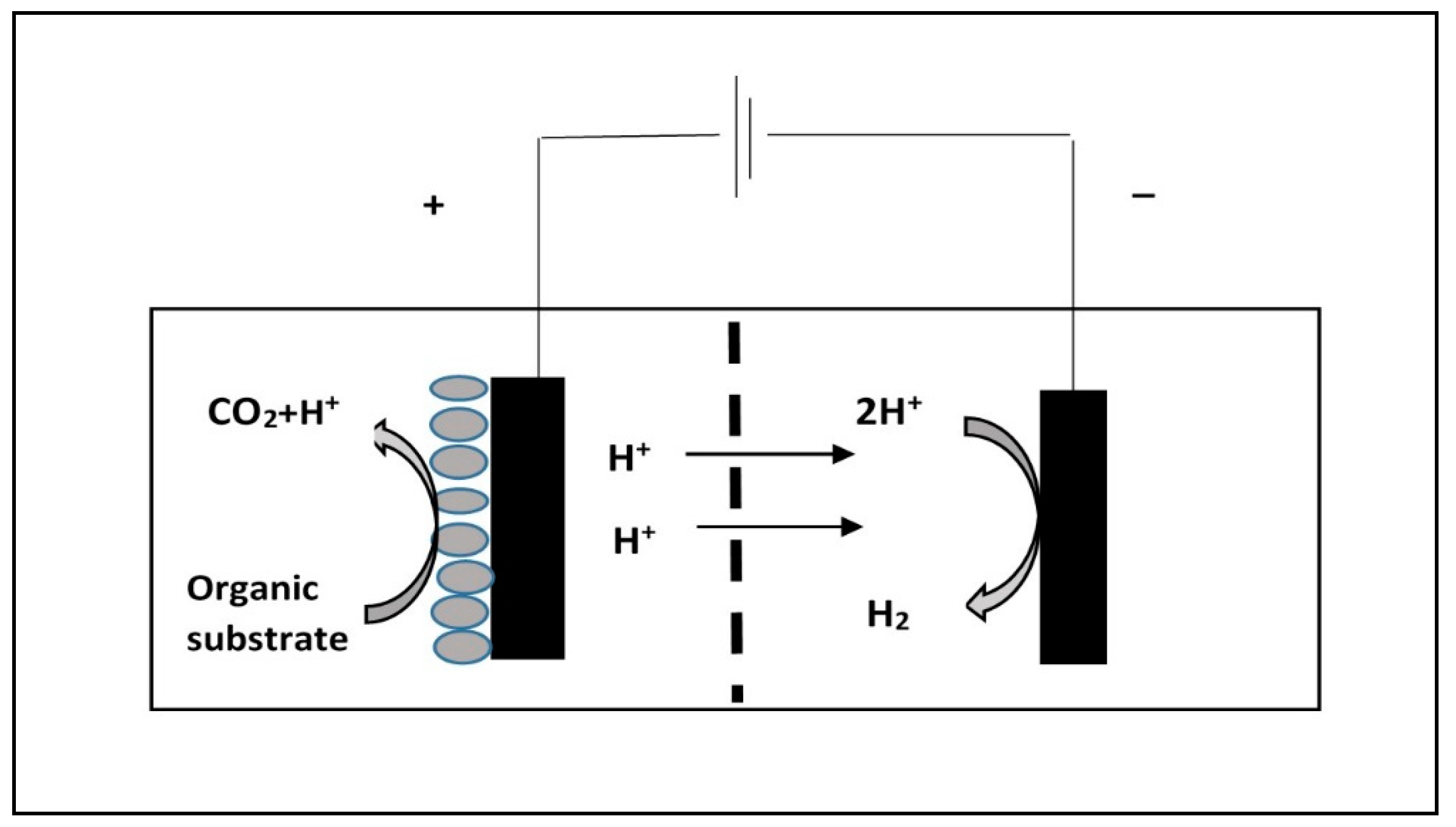
  43. Lee, H.S.; Lee, S.Y.; Yoo, K.; Kim, H.W.; Lee, E.; Im, N.G. Biohydrogen production and purification: Focusing on bioelectrochemical systems. Bioresour. Technol. 2022, 363, 127956. [Google Scholar] [CrossRef]
  44. Hassan, M.; Fernandez, A.S.; San Martin, I.; Xie, B.; Moran, A. Hydrogen evolution in microbial electrolysis cells treating landfill leachate: Dynamics of anodic biofilm. Int. J. Hydrogen Energy 2018, 43, 13051–13063. [Google Scholar] [CrossRef]
  45. Call, D.F.; Wagner, R.C.; Logan, B.E. Hydrogen Production by Geobacter Species and a Mixed Consortium in a Microbial Electrolysis Cell. Appl. Environ. Microbiol. 2009, 75, 7579–7587. [Google Scholar] [CrossRef]
  46. Escapa, A.; Mateos, R.; Martínez, E.J.; Blanes, J. Microbial electrolysis cells: An emerging technology for wastewater treatment and energy recovery. From laboratory to pilot plant and beyond. Renew. Sustain. Energy Rev. 2016, 55, 942–956. [Google Scholar] [CrossRef]
  47. Manish, S.; Banerjee, R. Comparison of bio-hydrogen production processes. Int. J. Hydrogen Energy 2008, 33, 279–286. [Google Scholar] [CrossRef]
  48. Banu, A.; Bicer, Y. Review on COx-free hydrogen from methane cracking: Catalysts, solar energy integration and applications. Energy Convers. Manag. X 2021, 12, 100117. [Google Scholar] [CrossRef]
  49. Muto, T.; Asahara, M.; Miyasaka, T.; Asato, K.; Uehara, T.; Koshi, M. Methane pyrolysis characteristics for the practical application of hydrogen production system using permalloy plate catalyst. Chem. Eng. Sci 2022, 237, 117931. [Google Scholar] [CrossRef]
  50. Su, B.; Wang, Y.; Xu, Z.; Han, W.; Jin, H.; Wang, H. Novel ways for hydrogen production based on methane steam and dry reforming integrated with carbon capture. Energy Convers. Manag. 2022, 270, 116199. [Google Scholar] [CrossRef]
  51. Park, M.J.; Kim, H.M.; Gu, Y.J.; Jeong, D.W. Optimization of biogas-reforming conditions considering carbon formation, hydrogen production, and energy efficiencies. Energy 2023, 265, 126273. [Google Scholar] [CrossRef]
  52. Levikhin, A.A.; Boryaev, A.A. Energy-saving, environmentally friendly production of hydrogen from the hydrocarbon feed. Sustain. Energy Technol. Assess 2022, 54, 102876. [Google Scholar] [CrossRef]
  53. Van de Krol, R.; Grätzel, M. Photoelectrochemical Hydrogen Production; Springer: New York, NY, USA; Dordrecht, The Netherlands; Heidelberg, Germany; London, UK, 2012; Volume 1, pp. 3–12. Available online: https://link.springer.com/book/10.1007/978-1-4614-1380-6 (accessed on 19 July 2023).
  54. Peng, J.; Wang, Y.; Bai, J.; Ma, D.; Zhao, R.; Han, J.; Wang, L. High-efficiency hollow Zn0.98Cu0.02Se/ZnS/ZnTiO3 photocatalyst for hydrogen production application. Fuel 2022, 325, 124937. [Google Scholar] [CrossRef]
  55. Karayel, G.K.; Javani, N.; Dincer, I. Hydropower energy for green hydrogen production in Turkey. Int. J. Hydrogen Energy 2023, 48, 22806–22817. [Google Scholar] [CrossRef]
  56. Luo, Z.; Wang, X.; Wen, H.; Pei, A. Hydrogen production from offshore wind power in South China. Int. J. Hydrogen Energy 2022, 47, 24558–24568. [Google Scholar] [CrossRef]
  57. Raab, M.; Körner, R.; Dietrich, R.U. Techno-economic assessment of renewable hydrogen production and the influence of grid participation. Int. J. Hydrogen Energy 2022, 47, 26798–26811. [Google Scholar] [CrossRef]
  58. Shah, M.; Prajapati, M.; Yadav, K.; Sircar, A. A review of the geothermal integrated hydrogen production system as a sustainable way of solving potential fuel shortages. J. Clean. Prod. 2022, 380, 135001. [Google Scholar] [CrossRef]
  59. Damyanova, S.; Pawelec, B.; Arishtirova, K.; Fierro, J.L.G. Ni-based catalysts for reforming of methane with CO2. Int. J. Hydrogen Energy 2012, 37, 15966–15975. [Google Scholar] [CrossRef]
  60. Ji, M.; Wang, J. Review and comparison of various hydrogen production methods based on costs and life cycle impact assessment indicators. Int. J. Hydrogen Energy 2021, 46, 38612–38635. [Google Scholar] [CrossRef]
  61. Chantawan, N.; Moungprayoon, A.; Lunprom, S.; Reungsang, A.; Salakkam, A. High-solid dark fermentation of cassava pulp and cassava processing wastewater for hydrogen production. Int. J. Hydrogen Energy 2022, 47, 40672–40682. [Google Scholar] [CrossRef]
  62. Chen, W.; Li, T.; Ren, Y.; Wang, J.; Chen, H.; Wang, Q. Biological hydrogen with industrial potential: Improvement and prospection in biohydrogen production. J. Clean. Prod. 2023, 387, 135777. [Google Scholar] [CrossRef]
  63. Chittibabu, G.; Nath, K.; Das, D. Feasibility studies on the fermentative hydrogen production by recombinant Escherichia coli BL-21. Process Biochem. 2006, 41, 682–688. [Google Scholar] [CrossRef]
  64. Mei, D.; Qiu, X.; Liu, H.; Wu, Q.; Yu, S.; Xu, L.; Zuo, T.; Wang, Y. Progress on methanol reforming technologies for highly efficient hydrogen production and applications. Int. J. Hydrogen Energy 2022, 47, 35757–35777. [Google Scholar] [CrossRef]
  65. Kulprathipanja, A.; Falconer, J.L. Partial oxidation of methanol for hydrogen production using ITO/Al2O3 nanoparticle catalysts. Appl. Catal. A Gen. 2004, 261, 77–86. [Google Scholar] [CrossRef]
  66. Gao, F.; Zhan, H.; Zeng, Z.Y. A methanol autothermal reforming system for the enhanced hydrogen production: Process simulation and thermodynamic optimization. Int. J. Hydrogen Energy 2023, 48, 1758–1772. [Google Scholar] [CrossRef]
  67. Aziz, M.; Wijayanta, A.T.; Nandiyanto, A.B.D. Ammonia as Effective Hydrogen Storage: A Review on Production, Storage and Utilization. Energies 2020, 13, 3062. [Google Scholar] [CrossRef]
  68. Kurtz, J.; Sprik, S.; Bradley, T.H. Review of transportation hydrogen infrastructure performance and reliability. Int. J. Hydrogen Energy 2019, 44, 12010–12023. [Google Scholar] [CrossRef]
  69. Ganev, E.; Ivanov, B.; Vaklieva-Bancheva, N.; Kirilova, E.; Dzhelil, Y. A Multi-Objective Approach toward Optimal Design of Sustainable Integrated Biodiesel/Diesel Supply Chain Based on First- and Second-Generation Feedstock with Solid Waste Use. Energies 2021, 14, 2261. [Google Scholar] [CrossRef]
  70. Yang, Y.; Tong, L.; Yin, S.; Liu, Y.; Wang, L.; Qiu, Y.; Ding, Y. Status and challenges of applications and industry chain technologies of hydrogen in the context of carbon neutrality. J. Clean. Prod. 2022, 376, 134347. [Google Scholar] [CrossRef]
  71. Midilli, A.; Kucuk, H.; Topal, M.E.; Akbulut, U.; Dincer, I. A comprehensive review on hydrogen production from coal gasification: Challenges and Opportunities. Int. J. Hydrogen Energy 2021, 46, 25385–25412. [Google Scholar] [CrossRef]
  72. Chi, J.; Yu, H. Water electrolysis based on renewable energy for hydrogen production. Chin. J. Catal 2018, 39, 390–394. [Google Scholar] [CrossRef]
  73. Ma, Y.; Wang, X.R.; Li, T.; Zhang, J.; Gao, J.; Sun, Z. Hydrogen and ethanol: Production, storage, and transportation. Int. J. Hydrogen Energy 2021, 46, 27330–27348. [Google Scholar] [CrossRef]
  74. Singla, S.; Shetti, N.P.; Basu, S.; Mondal, K.; Aminabhavi, T.M. Hydrogen production technologies—membrane based separation, storage and challenges. J. Environ. Manag. 2022, 302, 113963. [Google Scholar] [CrossRef] [PubMed]
  75. Ganev, E.; Beschkov, V. Optimal synthesis and management of supply chains for production and utilization of biogas. Bul. Chem. Commun. 2022, 54, 205–210. [Google Scholar]
  76. ARC4 Climate Change 2007: Synthesis Report, Intergovernmental Panel on Climate Change (IPCC), Fourth Assessment Report. 2007. Available online: https://www.ipcc.ch/assessment-report/ar4/ (accessed on 23 February 2022).
  77. Dillon, A.C.; Heben, M.J. Hydrogen storage using carbon adsorbents: Past, present and future. Appl. Phys. A 2001, 72, 133–142. [Google Scholar] [CrossRef]
  78. Schlapbach, L.; Zuttel, A. Hydrogen storage for mobile applications. Nature 2001, 414, 353–358. [Google Scholar] [CrossRef]
  79. Satyapal, S.; Petrovic, J.; Read, C.; Thomas, G.; Ordaz, G. The U.S. Department of Energy’s National Hydrogen Storage Project: Progress towards meeting hydrogen-powered vehicle requirements. Catal. Today 2007, 120, 246–256. [Google Scholar] [CrossRef]
  80. Bogdanović, B.; Schwickardi, M. Ti-doped alkali metal aluminium hydrides as potential novel reversible hydrogen storage. J. Alloys Compd. 1997, 253–254, 1–9. [Google Scholar] [CrossRef]
  81. Li, Y.; Yang, R.T. Significantly enhanced hydrogen storage in metal organic frameworks via spillover. J. Am. Chem. Soc. 2006, 128, 726–727. [Google Scholar] [CrossRef] [PubMed]
  82. Hirscher, M. Handbook of Hydrogen Storage New Materials for Future Energy Storage; Weinheim Wiley-VCH-Verl: Weinheim, Germany, 2010. [Google Scholar] [CrossRef]
  83. Bigelow, E.; Lewis, M. Conformable Hydrogen Storage Pressure Vessel; Center for Transportation and the Environment: Atlanta, GA, USA, 2018. [Google Scholar] [CrossRef]
  84. Niaz, S.; Manzoor, T.; Pandith, A.H. Hydrogen storage: Materials, methods and perspectives. Renew. Sustain. Energy Rev. 2015, 50, 457–469. [Google Scholar] [CrossRef]
  85. Sakintuna, B.; Lamari-Darkrim, F.; Hirscher, M. Metal hydride materials for solid hydrogen storage: A review. Int. J. Hydrogen Energy 2007, 32, 1121–1140. [Google Scholar] [CrossRef]
  86. Andreasen, A.; Vegge, T.; Pedersen, A.S. Dehydrogenation kinetics of as-received and ball-milled LiAlH4. J. Solid State Chem. 2005, 178, 3672–3678. [Google Scholar] [CrossRef]
  87. Vajo, J.J.; Skeith, S.L.; Mertens, F. Reversible storage of hydrogen in destabilized LiBH4. J. Phys. Chem. C 2005, 109, 3719–3722. [Google Scholar] [CrossRef] [PubMed]
  88. Chlopek, K.; Frommen, C.; Leon, A.; Zabara, O.; Fichtner, M. Synthesis and properties of magnesium tetrahydroborate. J. Mater. Chem. 2007, 17, 3496–3503. [Google Scholar] [CrossRef]
  89. Feaver, A.; Sepehri, S.; Shamberger, P.; Stowe, A.; Autrey, T.; Cao, G. Coherent carbon cryogel—Ammonia borane nanocomposites for H2 storage. J. Phys. Chem. B 2007, 111, 7469–7472. [Google Scholar] [CrossRef]
  90. Labrousse, J.; Belasfar, K.; Aziz, O.; El Kenz, A.; Benyoussef, A. First principles study of BC7 monolayer compared to graphene as an ultra-high-capacity sheet for hydrogen storage applications. Diam. Relat. Mater 2023, 131, 109523. [Google Scholar] [CrossRef]
  91. Chen, J.; Dou, S.X.; Liu, H.K. Crystalline Mg2Ni obtained by mechanical alloying. J. Alloys Compd. 1996, 244, 184–189. [Google Scholar] [CrossRef]
  92. Zaluska, A.; Zaluski, L.; Ström-Olsen, J.O. Synergy of hydrogen sorption in ball-milled hydrides of Mg and Mg2Ni. J. Alloys Compd. 1999, 289, 197–206. [Google Scholar] [CrossRef]
  93. Imamura, H.; Masanari, K.; Kusuhara, M.; Katsumoto, H.; Sumi, T.; Sakata, Y. High hydrogen storage capacity of nanosized magnesium synthesized by high energy ball-milling. J. Alloys Compd. 2005, 386, 211–216. [Google Scholar] [CrossRef]
  94. Zhu, M.; Wang, H.; Ouyang, L.Z.; Zeng, M.Q. Composite structure and hydrogen storage properties in Mg-base alloys. Int. J. Hydrogen Energy 2006, 31, 251–257. [Google Scholar] [CrossRef]
  95. Wiswall, R. Topics in applied physics. Hydrog. Met. II 1978, 29, 209. [Google Scholar]
  96. Fukai, Y. The Metal–Hydrogen System, Basic Bulk Properties; Springer Series in Materials Science; Springer: Berlin/Heidelberg, Germany, 1993. [Google Scholar]
  97. Zaluska, A.; Zaluski, L.; Ström–Olsen, J.O. Nanocrystalline magnesium for hydrogen storage. J. Alloys Compd. 1999, 288, 217–225. [Google Scholar] [CrossRef]
  98. Barkhordarian, G.; Klassen, T.; Bormann, R. Effect of Nb2O5 content on hydrogen reaction kinetics of Mg. J. Alloys Compd. 2004, 364, 242–246. [Google Scholar] [CrossRef]
  99. Bogdanović, B.; Bohmhammel, K.; Christ, B.; Reiser, A.; Schlichte, K.; Vehlen, R.; Wolf, U. Thermodynamic investigation of the magnesium–hydrogen system. J. Alloys Compd. 1999, 282, 84–92. [Google Scholar] [CrossRef]
  100. Grochala, W.; Edwards, P.P. Thermal decomposition of the non-interstitial hydrides for the storage and production of hydrogen. Chem. Rev. 2004, 104, 1283–1315. [Google Scholar] [CrossRef] [PubMed]
  101. Mosquera-Vargas, E.; Tamayo, R.; Morel, M.; Roble, M.; Díaz-Droguett, D.E. Hydrogen storage in purified multi-walled carbon nanotubes: Gas hydrogenation cycles effect on the adsorption kinetics and their performance. Heliyon 2021, 7, 08494. [Google Scholar] [CrossRef]
  102. Shet, S.P.; Priya, S.S.; Sudhakar, K.; Tahir, M. A review on current trends in potential use of metal-organic framework for hydrogen storage. Int. J. Hydrogen Energy 2021, 46, 11782–11803. [Google Scholar] [CrossRef]
  103. Cho, S.J.; Song, K.S.; Kim, J.W.; Kim, T.H.; Choo, K. Hydrogen Sorption in HCl-Treated Polyaniline and Polyoyrrole: New Potential Hydrogen Storage Media. Fuel Chem. Div. 2002, 47, 790. [Google Scholar]
  104. Attia, N.F.; Geckeler, K.E. Polyaniline–Polypyrrole Composites with Enhanced Hydrogen Storage Capacities. Macromol. Rapid Commun. 2013, 34, 931. [Google Scholar] [CrossRef]
  105. Sevilla, M.; Fuertes, A.B.; Mokaya, R. Preparation and hydrogen storage capacity of highly porous activated carbon materials derived from polythiophene. Int. J. Hydrogen Energy 2011, 36, 15658–15663. [Google Scholar] [CrossRef]
  106. Germain, J.; Frèchet, J.; Svec, F. Nanoporous, hypercrosslinked polypyrroles: Effect of crosslinking moiety on pore size and selective gas adsorption. Chem. Commun. 2009, 12, 1526–1549. [Google Scholar] [CrossRef] [PubMed]
  107. Joubert, J.M.; Latroche, M.; Percheron-Guégan, A. Metallic Hydrides II: Materials for Electrochemical Storage. MRS Bull. 2002, 27, 694–698. [Google Scholar] [CrossRef]
  108. Germain, J.; Fréchet, J.M.J.; Svec, F. Nanoporous Polymers for Hydrogen Storage. Small 2009, 5, 1098. [Google Scholar] [CrossRef] [PubMed]
Figure 1. Basic components of hydrogen-driven fuel cell.
Energies 16 06108 g001
Figure 2. Hydrogen fuel cell electric vehicle [14].
Energies 16 06108 g002
Figure 3. A sketch of the capillary-fed electrolysis cell [35].
Energies 16 06108 g003
Figure 4. A sketch of microbial electrolysis for hydrogen production with electrogenic bacteria immobilized on the anode. Dashed line denotes the proton-permeable membrane. The ovals denote the immobilized exo-electrogenic bacteria. Anode (+) and cathode (−).
Energies 16 06108 g004
Figure 5. A principal scheme of hydrogen production by natural gas steam reforming.
Energies 16 06108 g005
Figure 6. Flowsheet for hydrogen production from biomass, see ref. [47].
Energies 16 06108 g006
Figure 7. Principal sketch of ammonia conversion into hydrogen.
Energies 16 06108 g007
Figure 8. Illustration of life cycle assessment of hydrogen use [70,71,72,73,74].
Energies 16 06108 g008
Figure 9. Sustainable development and management concept of integrated hydrogen supply chain (IHSC) [75].
Energies 16 06108 g009
Figure 10. Superstructure of the integrated hydrogen supply chain.
Energies 16 06108 g010
Figure 11. Distribution of annual hydrogen demand in millions of tons of various items, adapted from [17].
Energies 16 06108 g011
Table 1. Different hydrogen “colors” depending on the process and their impact on environment.
ColorMethod of Hydrogen ProductionAdvantages/Drawback
GreenElectrolysis, based on renewable energy sources or their combination (solar and wind power)No greenhouse emissions. Expensive.
BlueSteam reforming of methane with carbon dioxide capturingCheap with high productivity. Carbon dioxide release with subsequent capturing and storage.
GreySteam reforming of methane without carbon dioxide capturingCheap with high productivity. Carbon dioxide release.
Black/brownGasification of coalCheap, but with adverse impact on environment.
PinkElectrolysis by nuclear power station electricityUses the surplus of produced electricity by nuclear power stations.
TurquoiseCatalytic methane pyrolysis with solid carbon as by-productProcess in development and still expensive.
YellowElectrolysis solely using solar energyNo greenhouse emissions.
Table 2. Hydrogen production rate and content in biogas by microbial electrolysis. Excerpt from Table 1 in [44].
SubstrateAnodic Potential vs. Ag/AgCl, VHydrogen Content in the Biogas, %vol.Hydrogen Production Rate, m3 m−3 day−1
Dairy
industry
0.8760.086
Food
processing
0.7860.8–1.8
Domestic wastewater1.11000.015
Table 3. Comparison of non-renewable energy consumption for different methods of hydrogen production. Excerpt from Table 4 in [47].
Method of ProductionNon-Renewable Energy (kWh) Use per 1 Nm3 HydrogenProcess Efficiency, %
Steam methane reforming4.6664
Dark fermentation1.529.6
Photo-fermentation0.9925.6
Two-stage fermentation0.9727.6
Microbial electrolysis1.6125.7
Disclaimer/Publisher’s Note: The statements, opinions and data contained in all publications are solely those of the individual author(s) and contributor(s) and not of MDPI and/or the editor(s). MDPI and/or the editor(s) disclaim responsibility for any injury to people or property resulting from any ideas, methods, instructions or products referred to in the content.

