
Experimental Study on Microscopic Water Flooding Mechanism of High-Porosity, High-Permeability, Medium-High-Viscosity Oil Reservoir

Abstract
:1. Introduction
2. Microfluidic Physical Simulation Method
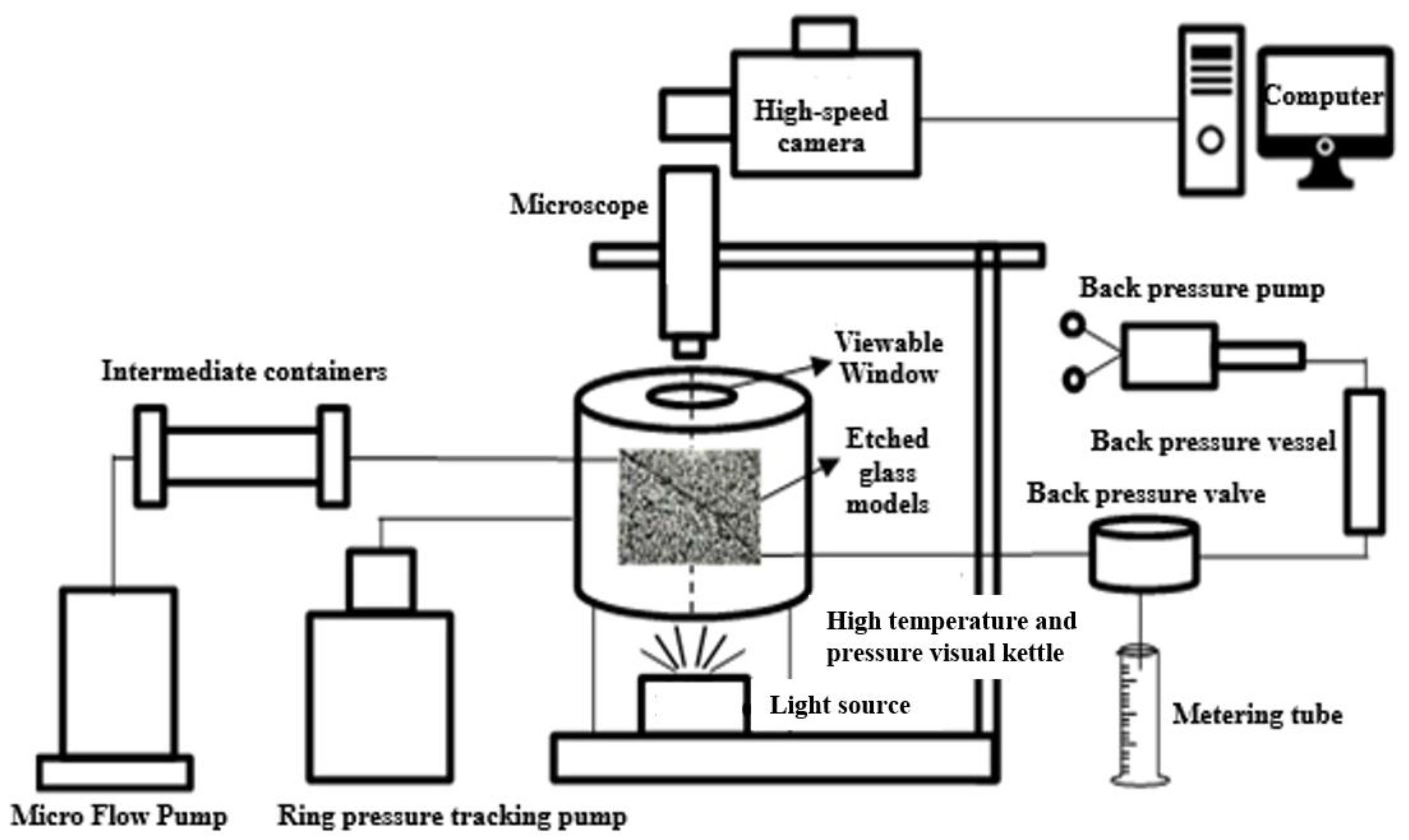
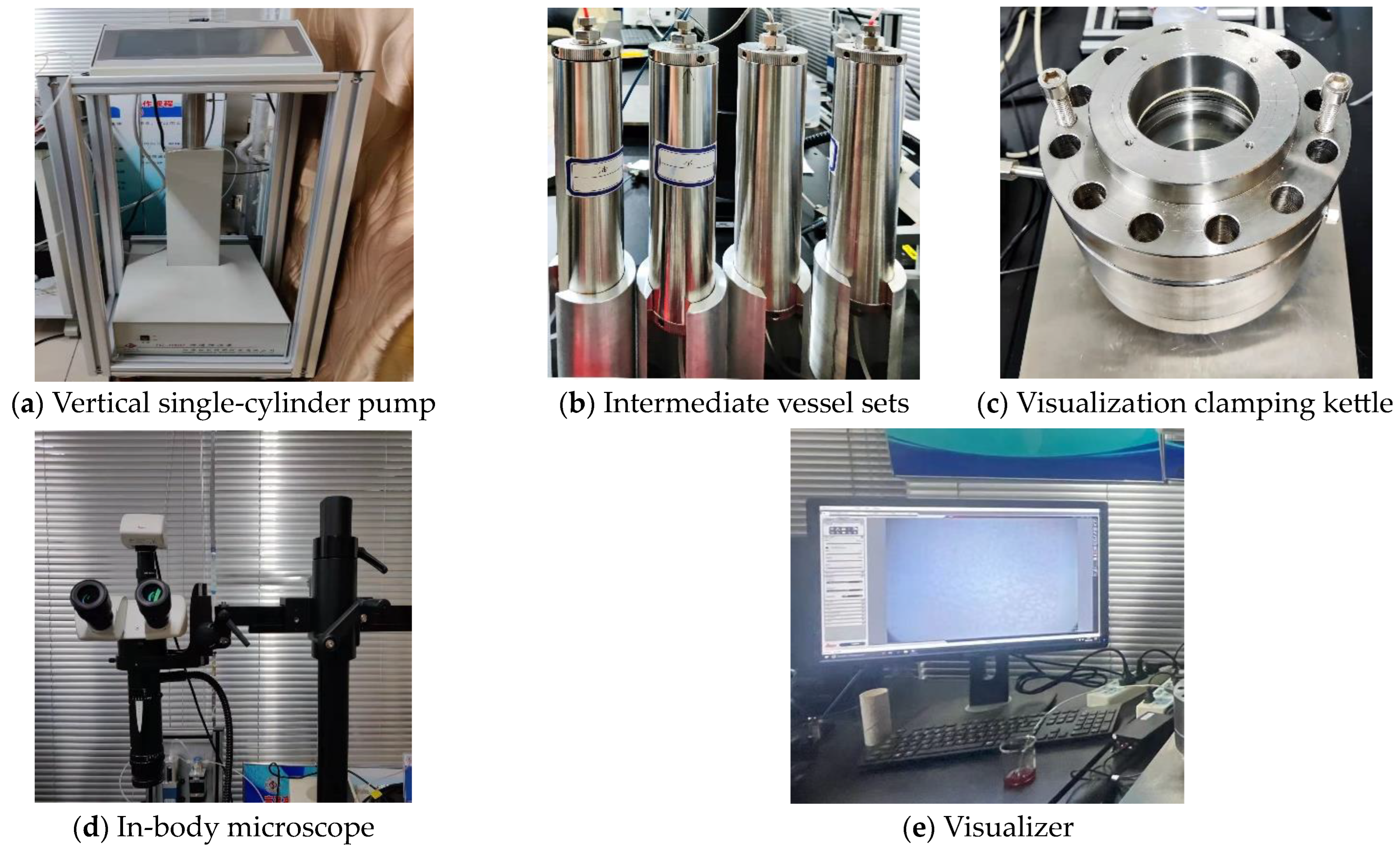
2.1. Experimental Equipment
2.2. Experimental Material
2.2.1. Fluid Simulation Methods
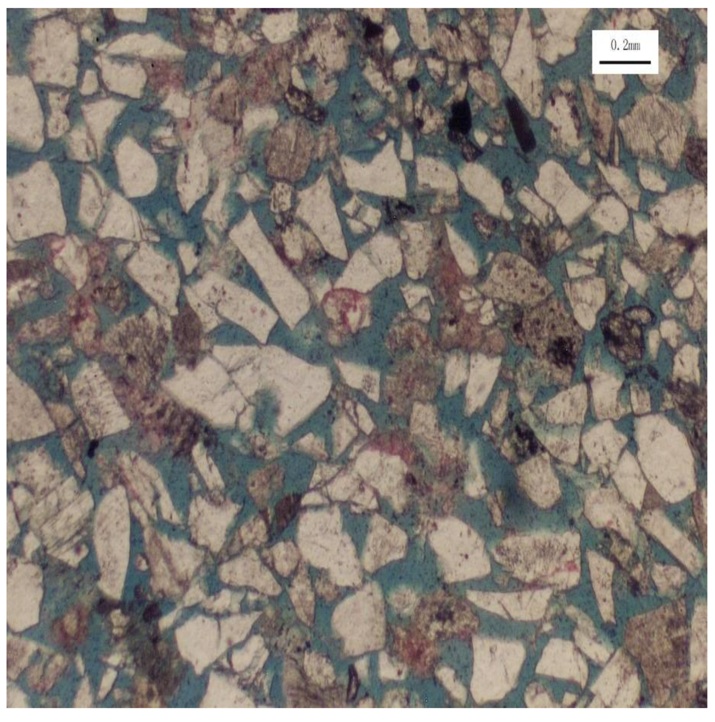
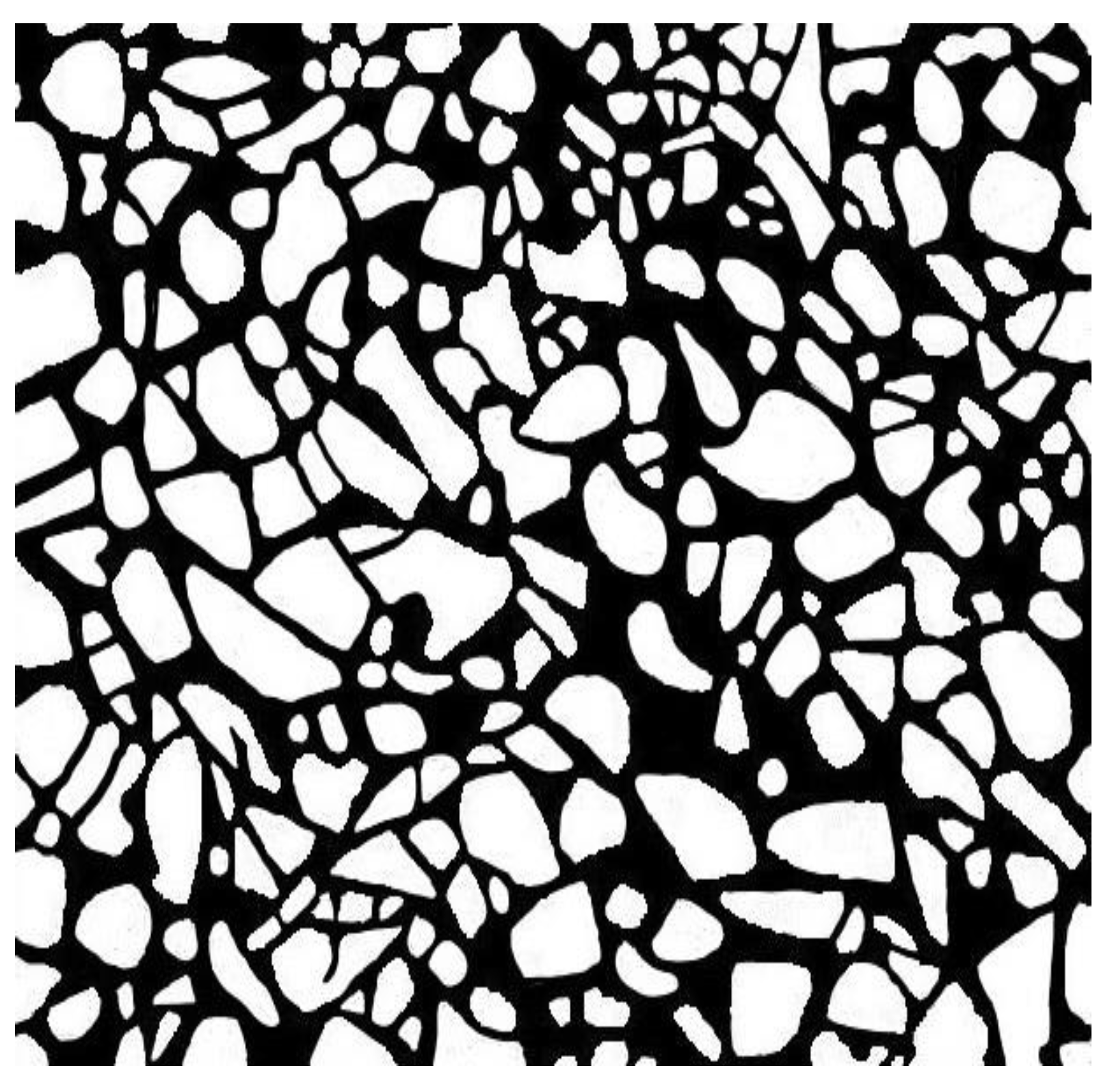
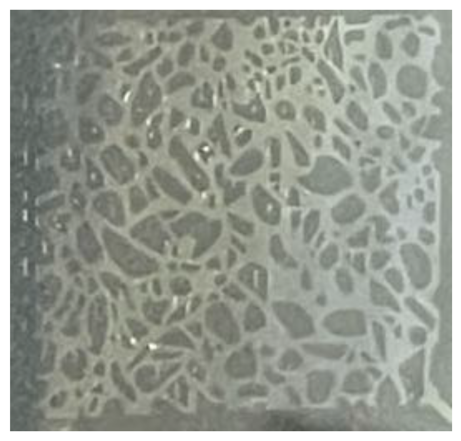
2.2.2. Reservoir Simulation Methods
3. Microfluidic Water Drive Experimental Design and Procedure
3.1. Experimental Programme Design
3.2. Experimental Procedure and Steps
3.2.1. Experimental Procedure
3.2.2. Experimental Steps
- ➀
- Pipeline design and connection
- ➁
- Preparation and assembly of experimental oil
- ➂
- Experimental water preparation and assembly
- ➃
- Assembly of hydrophobic agent and anhydrous ethanol
- ➄
- Etched glass model assembly
- ➅
- Saturated hydrophobic
- ➆
- Saturated oil
- ➇
- Water-driven oil
- ➈
- Model cleaning
4. Analysis of Experiment Results
4.1. Water Flooding Characteristics and Mechanism on the Microscale
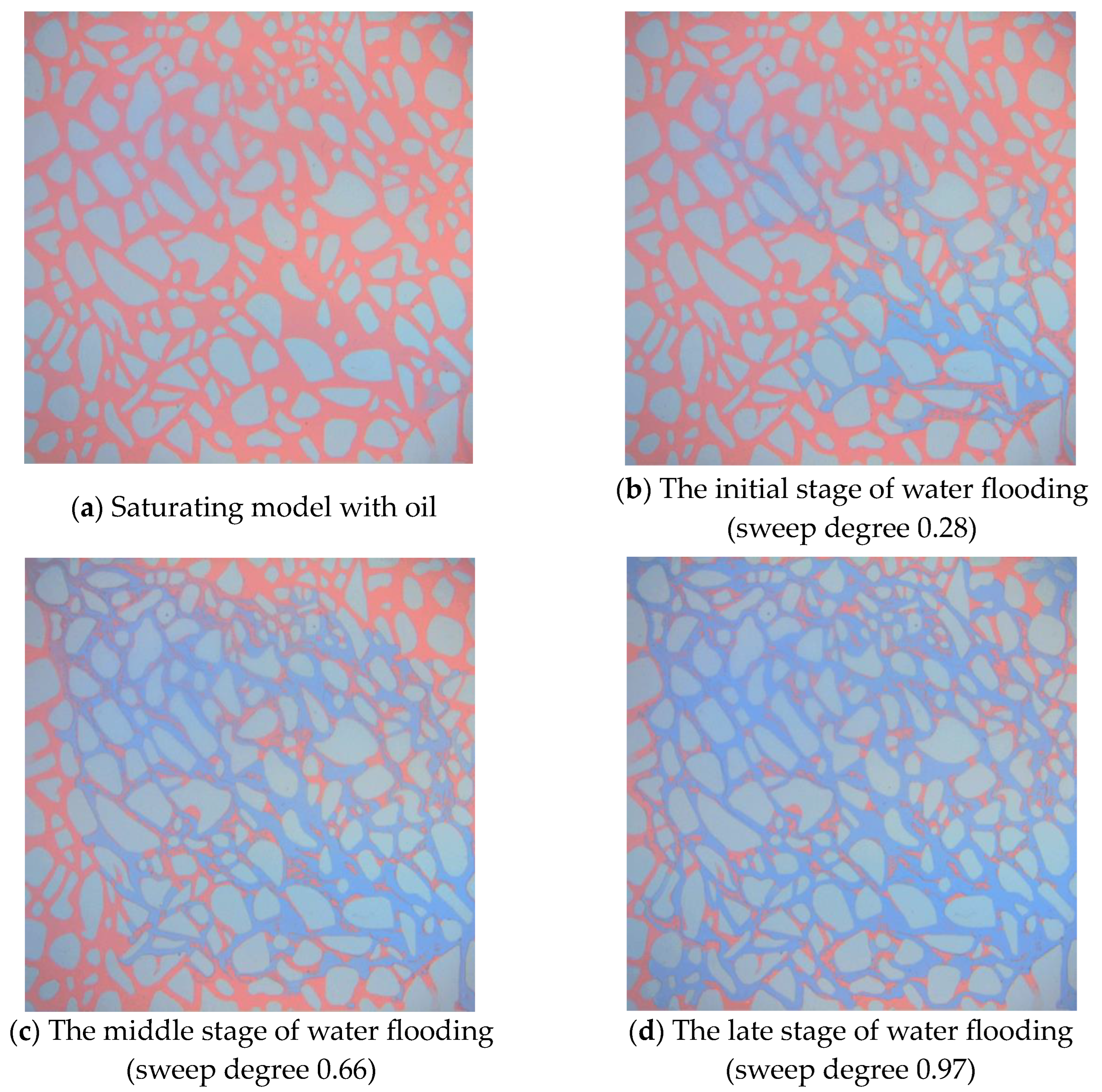
4.1.1. Water Flooding Characteristics on the Microscale
4.1.2. Water Flooding Mechanism on the Microscale
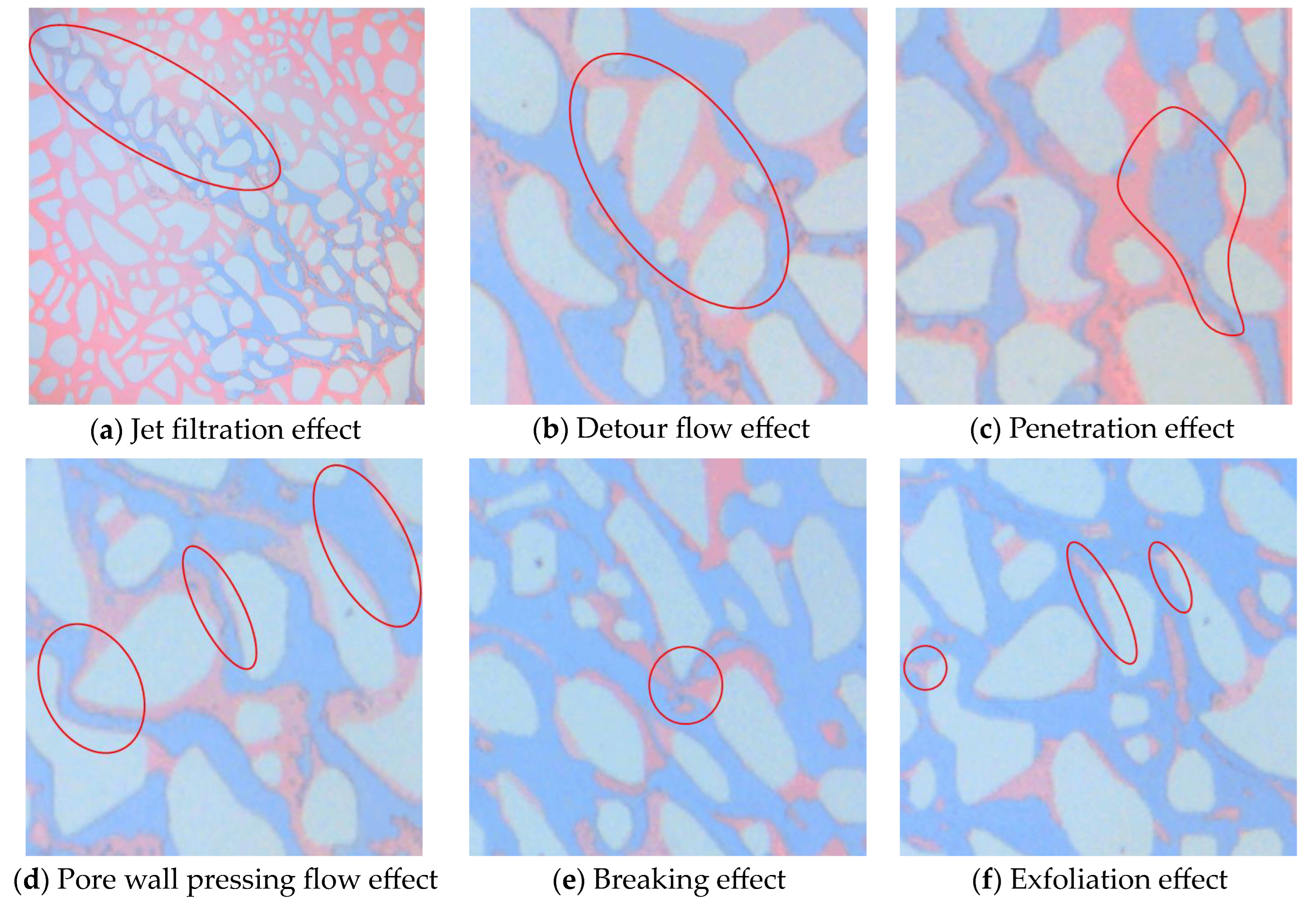
- ➀
- Jet filtration effect: The injected water advances along the connection between the inlet and outlet of the microscopic model to form the main stream line of flooding. The injected water advances fastest in this direction and forms a dominant channel. The main reasons for this phenomenon are the small size of the sample and the surface tension. The jet filtration phenomenon in the experimental process is shown in Figure 7.
- ➁
- Detour flow effect: Compared with the large pore throat area, the jamming stress in the small pore throat area is larger, the displacement resistance is larger, and the injected water will preferentially select the large pore throat area with a smaller jamming stress to flow. The flow effect during the experiment is shown in Figure 7.
- ➂
- Penetration effect: When the driving force of the simulated oil and the capillary force are far greater than the resistance composed of the viscous force between the crude oil and the displacement fluid and the maximum static friction force between the oil and the rock, the displacement fluid breaks through rapidly, and the simulated oil is displaced to form a channel. This phenomenon mainly occurs in areas with a larger pore throat radius or in areas where the pore throat radius gradually increases. The penetration effect in the experimental process is shown in Figure 7.
- ➃
- Pore wall pressing flow effect: The model skeleton in this experiment is lipophilic. The displacement force, composed of capillary force and driving force, is greater than the viscous force between crude oil and displacement fluid and less than the maximum static friction force between crude oil and rock. This leads to the injection of water to displace the simulated oil in the middle of the pore throat, and the crude oil remaining on the pore throat wall exists in the form of a film. The adherent flow of the simulated oil during the experiment is shown in Figure 7.
- ➄
- Breaking effect: In the process of water flooding, the simulated oil enters the pore throat from the large pore throat to the pore throat with a smaller radius. The capillary force as the driving force of displacement is affected by the jamming effect and becomes the displacement resistance, which makes the driving force of displacement decrease and the displacement resistance increase, resulting in the original continuous oil flow plunger or large oil droplets being blocked. The blocking effect during the experiment is shown in Figure 7.
- ➅
- Exfoliation effect: Due to the increase in displacement multiples, after the front end of the injected water is in contact with the surface of the simulated oil and rock particles, the simulated oil is stripped off the surface of the hole wall and driven by the driving force of the oil displacement. The stripping effect in the experimental process is shown in Figure 7.
4.2. Microscopic Remaining Oil Types and Evolution Law
4.2.1. Microscopic Remaining Oil Types
4.2.2. Microscopic Remaining Oil Evolution Law
- ➀
- In the early stages of water flooding, most of the area has not been effectively used, mainly with contiguous residual oil.
- ➁
- Due to the penetration effect, the continuous flake residual oil is divided into porous residual oil by the injected water.
- ➂
- The displacement of crude oil in the middle of the pores is relatively clean, and there is a large viscous force between the rock wall and the crude oil, forming a film-like remaining oil.
- ➃
- With the increase in displacement ratio, the stripping effect of injected water makes the membrane residual oil change to the striped residual oil.
- ➄
- Due to the blocking effect of pore throat and jamming effect, the striped remaining oil is divided into drip-shaped remaining oil.

4.3. The Main Controlling Factors of Different Types of Remaining Oil
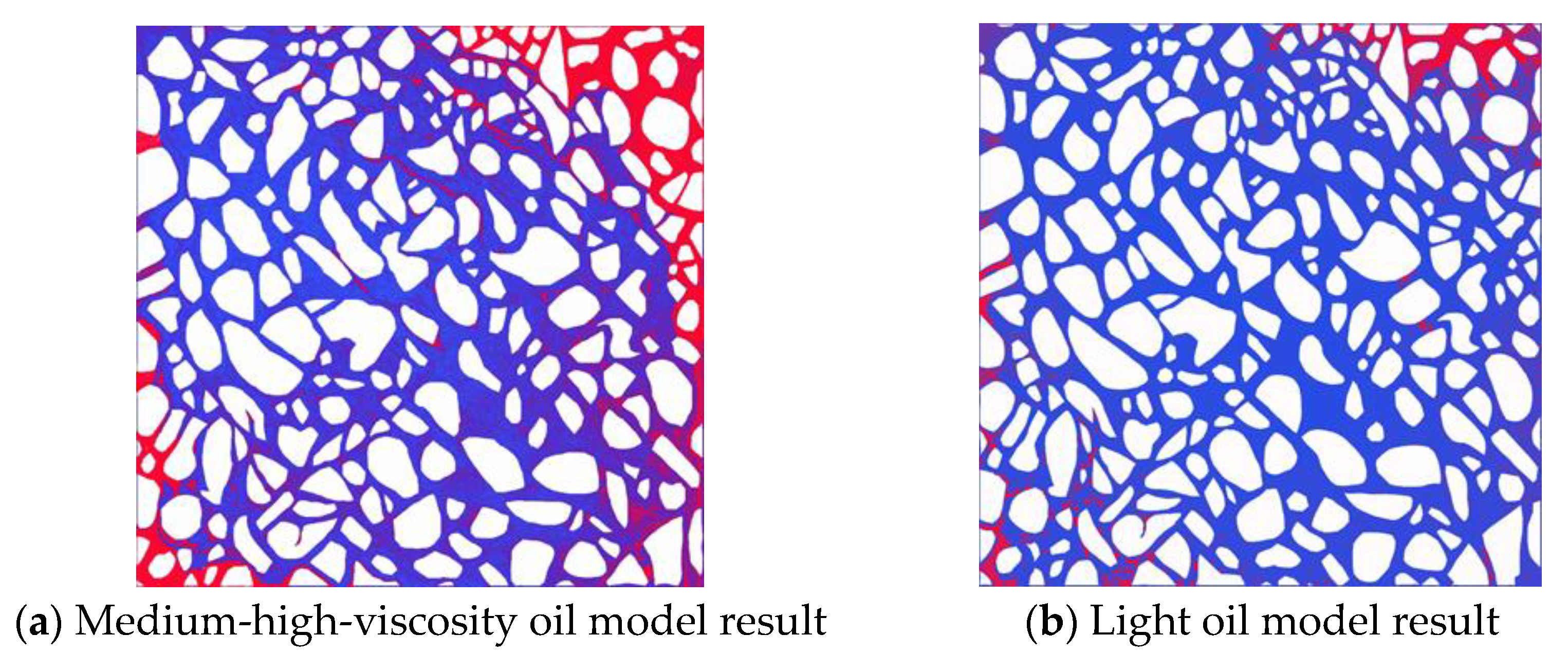
4.3.1. Microfluidic Experiments with Different Crude Oil Viscosity
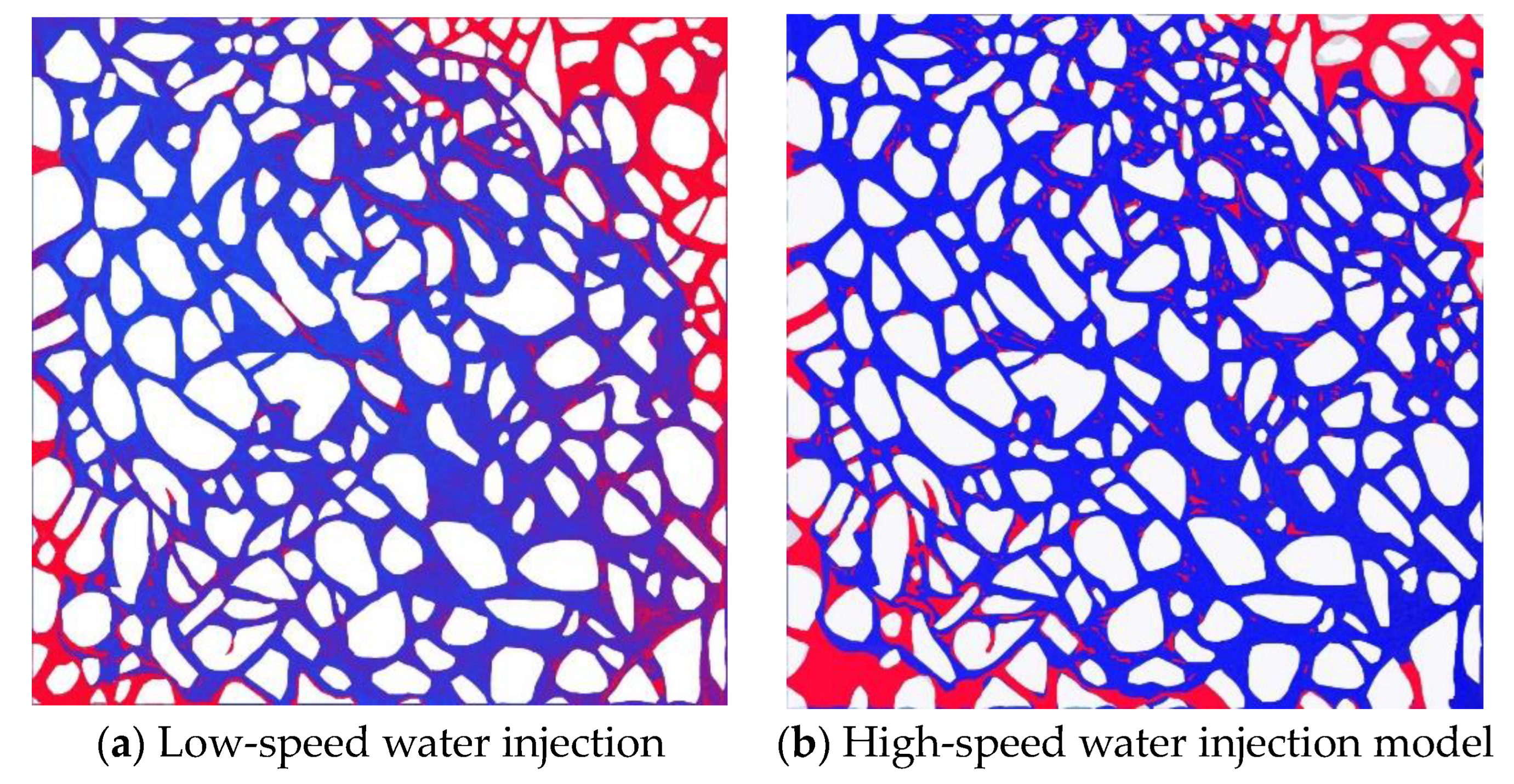
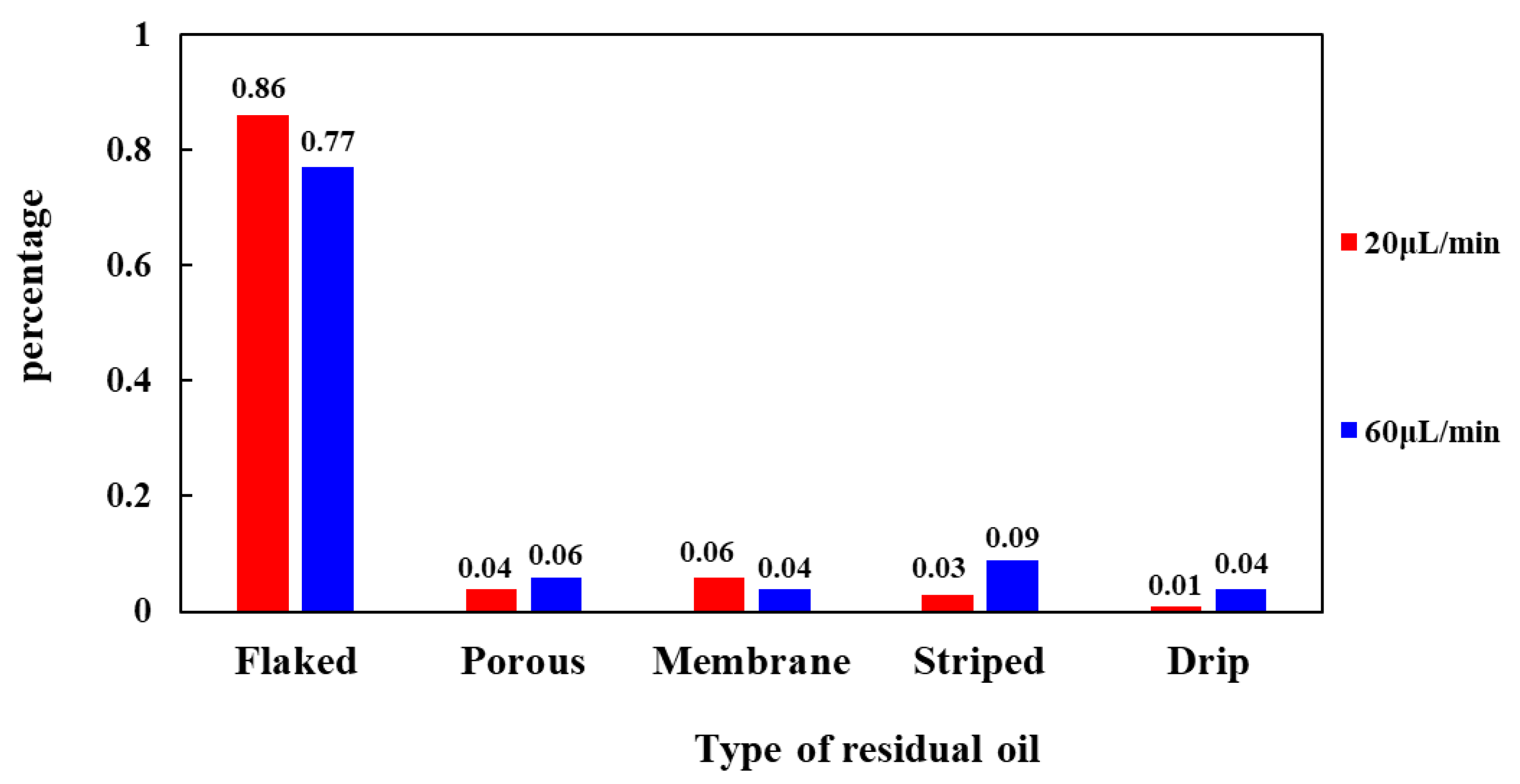
4.3.2. Microfluidic Experiments under Different Water Injection Intensities
5. Conclusions
- (1)
- Microscopic water drive characteristics: Injecting water in the form of filaments protruding along the connecting line between injection and production wells. As the water drive proceeds, the injected water spreads along the main flow line to the unrippled areas on both sides, and the extent of injected water rippling reaches almost 100% after the water breakthrough has happened at the export side. At the end of the water drive, the residual oil morphology and content hardly vary with the injection volume.
- (2)
- Microscopic water drive mechanism: The formation of microscopic residual oil is mainly due to jet filtration, penetration, bypassing, advective flow, stripping of the injected water, and seizing of the rock skeleton.
- (3)
- Microscopic residual oil classification: Based on the location, contact ratio, aspect ratio, shape factor, and number of pores and throats of residual oil, the residual oil was categorized into five types, i.e., contiguous residual oil, porous residual oil, membrane residual oil, strip residual oil, and drip residual oil.
- (4)
- Microscopic residual oil evolution pattern: As the water drive proceeds, the residual oil changes along the sequence of continuous sheet, porous, membrane, strip, and drip, in which the strip residual oil includes two kinds of direct formation and transformation of membrane residual oil.
- (5)
- Analysis of the main controlling factors of different types of residual oil: The main controlling factor for contiguous and porous residual oil is crude oil viscosity. The main reason is that the oil-water flow rate ratio is large, resulting in a serious jet filtration phenomenon, and the injection water forms a dominant seepage channel, leading to the existence of contiguous pieces of residual oil that are not effectively utilized. The main controlling factor for membrane, strip, and drip residual oil is injection intensity. High-rate water injection elevates the number of capillary tubes, which increases the driving force and transforms the membrane residual oil into strip and drip residual oil.
Author Contributions
Funding
Conflicts of Interest
References
- Yue, P.; Qu, S.M.; Li, F.H.; Wang, Q.L.; Zhang, L.; Luo, X.; Feng, X.; Ren, Y.W. Characteristics of residual oil distribution in high-porosity, high-permeability, high-water-content thick oil reservoirs and the main controlling factors of utilization. Unconv. Oil Gas 2023, 10, 33–42. [Google Scholar]
- Chatenever, A.; Calhoun, J.C., Jr. Visual examinations of fluid behavior in porous media—Part I. J. Pet. Technol. 1952, 4, 149–156. [Google Scholar] [CrossRef]
- Guo, S.P.; Huang, Y.Z.; Zhou, J. Micro-Mechanisms of Physicochemical Seepage; Science Press: Beijing, China, 1990. [Google Scholar]
- Li, J.J.; Su, H.; Jiang, H.; Yu, F.; Liang, T.; Zhao, Y.; Gao, Y.; Hossein, H. Application of microfluidic modeling in oil and gas field development. J. Pet. Sci. 2018, 3, 284–301. [Google Scholar]
- Xu, K.; Liang, T.; Zhu, P.; Qi, P.; Lu, J.; Huh, C.; Balhoff, M. A 2.5-D glass micromodel for investigation of multiphase flow in porous media. Lab. Chip. 2017, 17, 640–646. [Google Scholar] [CrossRef] [PubMed]
- Ginger, R.; Abedini, A.; Yang, H.; Sanders, A. Visualization of Flowback Aid Mechanisms Utilizing a Microfluidic Pore-Scale Device. In Proceedings of the International Conference and Exhibition on Formation Damage Control, SPE-199269-MS, Lafayette, LA, USA, 12 February 2020. [Google Scholar]
- Yuan, S.; Liang, T.B.; Zhou, F.J.; Liang, X.; Yu, F.; Li, J. A Microfluidic Study of Wettability Alteration Rate on Enhanced Oil Recovery in Oil-Wet Porous Media. In Proceedings of the Abu Dhabi International Petroleum Exhibition & Conference, SPE-197715-MS, Abu Dhabi, United Arab Emirates, 11 November 2019. [Google Scholar]
- Khayrullin, M.M.; Zakirov, T.R.; Grishin, P.A.; Shilov, E.D.; Bukatin, A. Methods for Studying Two-Phase Flows in Porous Media: Numerical Simulation and Experiments on Microfluidics Chips. In Proceedings of the Russian Petroleum Technology Conference, SPE-202022-MS, Virtual, 26 October 2020. [Google Scholar]
- Zhou, J.; Xue, H.; Zheng, D.W.; Liu, X.W. Seepage Mechanism of Water-driven Oil in Fractured Reservoirs. J. Chongqing Univ. Nat. Sci. Ed. 2000, S1, 65–67. [Google Scholar]
- Chen, Y.Y.; Sun, L.; Tian, T.H.; Pan, Y.; Dong, W.J.; Liu, Y.Z. Visual modeling of fractured carbonate reservoirs for water-driven oil experiments. Fault Block Oil Gas Fields 2012, 19, 92–94. [Google Scholar]
- Chen, M. Quantitative Characterization of Microscopic Seepage Mechanism in Water-Driven Reservoirs; Southwest Petroleum University: Chengdu, China, 2017. [Google Scholar]
- Alizadeh, A.H.; Khishvand, M.; Ioannidis, M.A.; Piri, M. Multi-scale experimental study of carbonated water injection: An effective process for mobilization and recovery of trapped oil. Fuel 2014, 132, 219–235. [Google Scholar] [CrossRef]
- Chen, X.L.; Han, H.S.; Li, S.; Yu, H.W. Microscopic characterization of residual oil in CO2-initiated blind-end pores. Oil Gas Geol. Recovery 2020, 27, 50–56. [Google Scholar]
- Cui, M.L.; Wang, R.; Lv, C.Y.; Lun, Z.M.; Zhao, S.X.; Tang, Y.Q. Microscopic oil drive mechanism of reinjected natural gas drive in high pressure and low permeability reservoirs. Oil Gas Geol. Recovery 2020, 27, 62–68. [Google Scholar]
- Li, J.; Jiang, H.; Wang, C.; Zhao, Y.; Gao, Y.; Pei, Y.; Wang, C.; Dong, H. Pore-scale investigation of microscopic remaining oil variation characteristics in water-wet sandstone using CT scanning. J. Nat. Gas Sci. Eng. 2017, 48, 36–45. [Google Scholar] [CrossRef]
- Wang, C.; Jiang, H.Q.; Ma, M.Q.; Xu, F.; Yu, F.W.; Zhao, Y.Y.; Li, J.J. Research on the change rule of residual oil flow state at pore scale based on microfluidic modeling. Pet. Sci. Bull. 2020, 5, 376–391. [Google Scholar]
- Li, Q.; Zhang, C.; Yang, Y.D.; Ansari, U.; Han, Y.; Li, X.; Cheng, Y. Preliminary experimental investigation on long-term fracture conductivity for evaluating the feasibility and efficiency of fracturing operation in offshore hydrate-bearing sediments. Ocean Eng. 2023, 281, 114949. [Google Scholar] [CrossRef]
- Li, Q.; Zhao, D.; Yin, J.; Zhou, X.; Li, Y.; Chi, P.; Han, Y.; Ansari, U.; Cheng, Y. Sediment Instability Caused by Gas Production from Hydrate-bearing Sediment in Northern South China Sea by Horizontal Wellbore: Evolution and Mechanism. Nat. Resour. Res. 2023, 32, 1595–1620. [Google Scholar] [CrossRef]


| Equipment Name | Equipment Type | Main Parameters of the Equipment |
|---|---|---|
| Vertical single-cylinder pump | TC-100D | Withstanding pressure 60 MPa; pressure accuracy 0.1% FS; Flow rate range 0.01–30 mL/min; single pump volume 100 mL |
| High-pressure intermediate vessel sets | ZJ-100 | Pressure resistance 60 MPa; Temperature resistance 150 °C; Vessel volume 100 mL; resolution 0.01 mL |
| In-body microscope | Leica Z16APO | Zoom 16:1; Main unit zoom range 0.57X–9.2X; Magnification 7.1X–115X; Maximum optical magnification 920X; Maximum resolving power 336 lp/mm; Large range of activity distance 97 mm |
| Visualization clamping kettle | HD1 | Pressure-resistant 60 MPa; temperature-resistant 150 °C; Can be covered with half-open heating jacket, half-open heat preservation sleeve, temperature control by electric heating and connected to the pressure and temperature monitoring system |
| Sample Number | Maximum/Major Particle Size Range (mm) | Sorting | Composition of Structural Particles (%) | GAP-Filler | Plane Porosity | |||||
|---|---|---|---|---|---|---|---|---|---|---|
| Quartz | Feldspar | Rock Waste | Else | Matrix | Cement | Intergranular Pore | Intragranular Pore | |||
| 1-001A | 0.52/0.15~0.35 | medium | 38 | 46 | 13.5 | 2.5 | 1 | 0.5 | 28 | 3 |
| Serial Number | Modeled Permeability (md) | Crude Oil Viscosity (mPa·s) | Filling Rate (mL/min) | Injection-Production Direction | Research Purpose |
|---|---|---|---|---|---|
| 1 | 2000 | 20 | 0.02 | Diagonal injection and production | Basic program |
| 2 | 2000 | 2 | 0.02 | Diagonal injection and production | Exploring the effect of crude oil viscosity on water drive effectiveness |
| 3 | 2000 | 20 | 0.06 | Diagonal injection and production | Exploring the effect of injection rate on water drive effect |
| Occurrence Type | Microscopic Remaining Oil Types | Occurrence Location | Contact Ratio | Aspect Ratio | Shape Factor | Pore-Throat Number |
|---|---|---|---|---|---|---|
| Capture | Continuous flake shape | Pore, throat | ≥0.5 | / | <0.33 | >5 |
| Porous shape | Pore, throat | ≥0.5 | / | <0.33 | ≤5 | |
| Half capture | Membrane shape | Particle surface | ≤0.5 | ≥2 | <0.33 | / |
| Discrete | Striped shape | Pore, throat | =0 | ≥2 | <0.33 | / |
| Drip shape | Pore | =0 | ≤2 | 0.33~0.67 | / |
Disclaimer/Publisher’s Note: The statements, opinions and data contained in all publications are solely those of the individual author(s) and contributor(s) and not of MDPI and/or the editor(s). MDPI and/or the editor(s) disclaim responsibility for any injury to people or property resulting from any ideas, methods, instructions or products referred to in the content. |
© 2023 by the authors. Licensee MDPI, Basel, Switzerland. This article is an open access article distributed under the terms and conditions of the Creative Commons Attribution (CC BY) license (https://creativecommons.org/licenses/by/4.0/).
Share and Cite
Li, Y.; Jia, P.; Li, M.; Feng, H.; Peng, C.; Cheng, L. Experimental Study on Microscopic Water Flooding Mechanism of High-Porosity, High-Permeability, Medium-High-Viscosity Oil Reservoir. Energies 2023, 16, 6101. https://doi.org/10.3390/en16176101
Li Y, Jia P, Li M, Feng H, Peng C, Cheng L. Experimental Study on Microscopic Water Flooding Mechanism of High-Porosity, High-Permeability, Medium-High-Viscosity Oil Reservoir. Energies. 2023; 16(17):6101. https://doi.org/10.3390/en16176101
Chicago/Turabian StyleLi, Yang, Pin Jia, Ming Li, Haoran Feng, Cong Peng, and Linsong Cheng. 2023. "Experimental Study on Microscopic Water Flooding Mechanism of High-Porosity, High-Permeability, Medium-High-Viscosity Oil Reservoir" Energies 16, no. 17: 6101. https://doi.org/10.3390/en16176101
APA StyleLi, Y., Jia, P., Li, M., Feng, H., Peng, C., & Cheng, L. (2023). Experimental Study on Microscopic Water Flooding Mechanism of High-Porosity, High-Permeability, Medium-High-Viscosity Oil Reservoir. Energies, 16(17), 6101. https://doi.org/10.3390/en16176101