
Demagnetization Modeling and Analysis for a Six-Phase Surface-Mounted Field-Modulated Permanent-Magnet Machine Based on Equivalent Magnetic Network


Abstract
:1. Introduction
2. EMN Modeling of Six-Phase Surface-Mounted FMPMM under Demagnetization
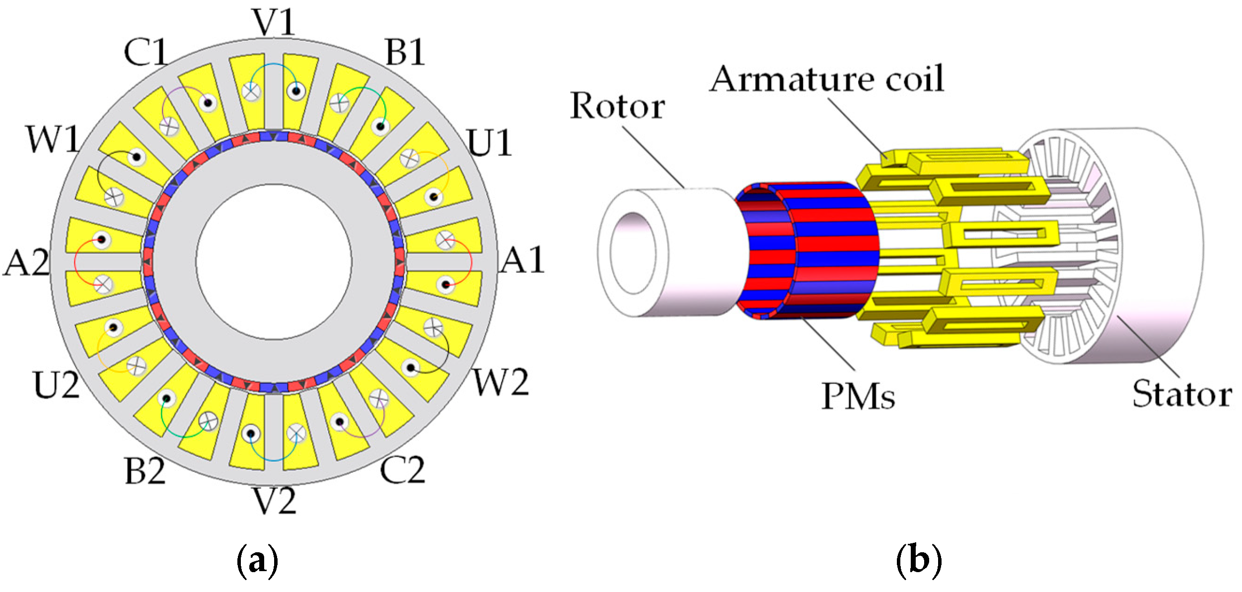
2.1. Machine Topology
2.2. Magnetic Field Distribution
2.3. Stator EMN Model
2.4. Rotor EMN Model
2.5. Air-Gap EMN Model
3. Calculation Process of the Proposed EMN Model
3.1. Iterative Calculation
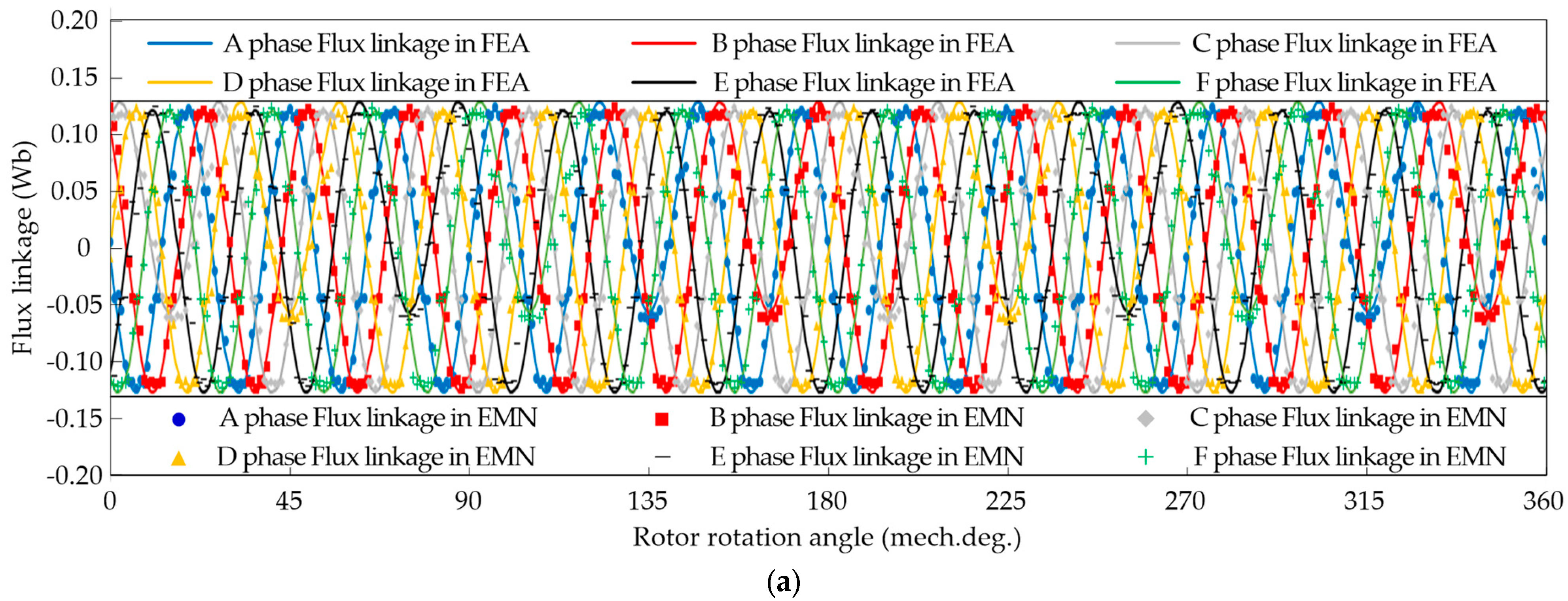
3.2. Air-Gap Flux Density and Back-EMF Calculation
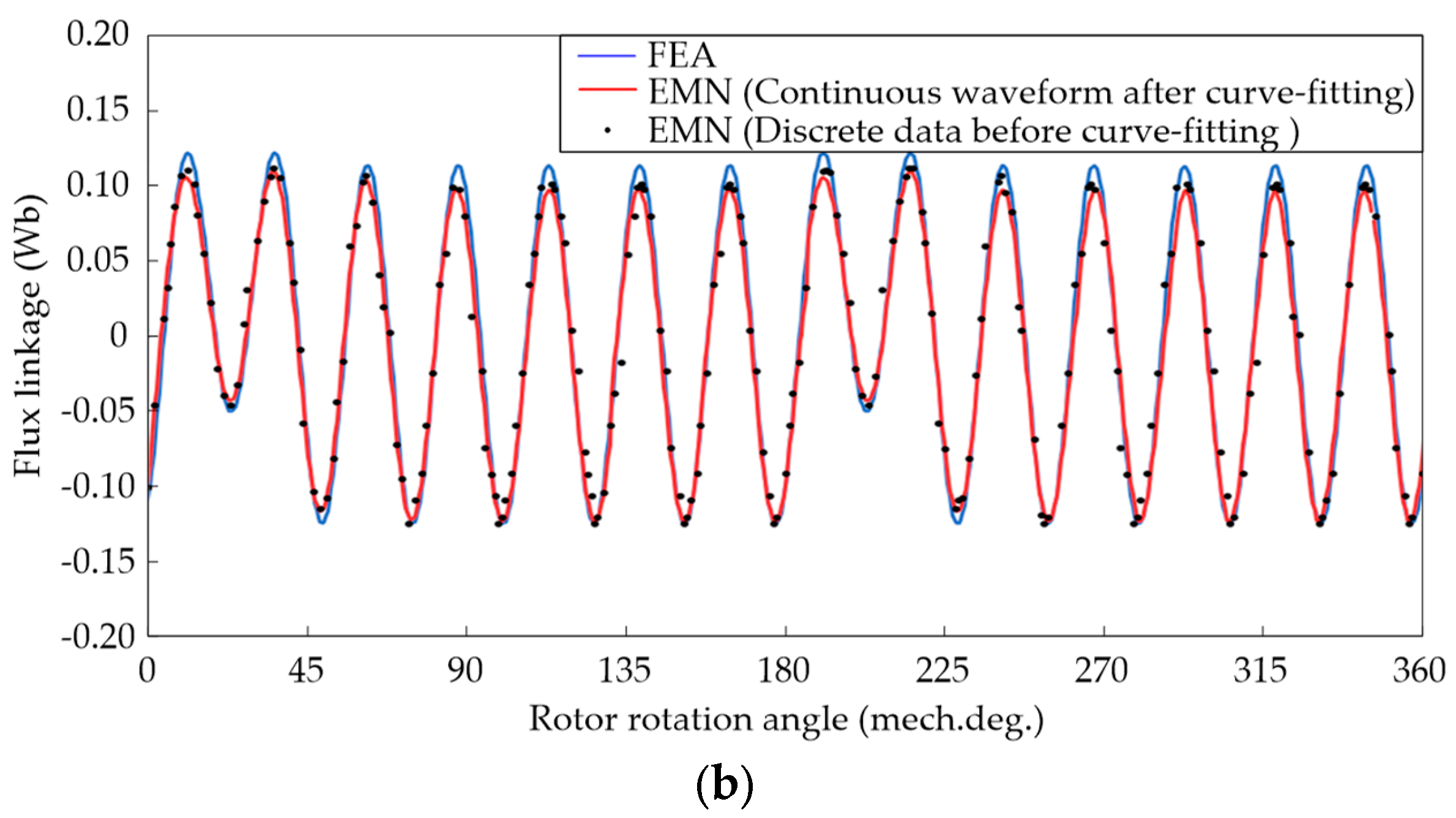
3.3. Curve-Fitting Method
4. Comparison Analysis with the FEA
4.1. Parameter Setting

| Groups | Types | Demagnetization Degree | ||
|---|---|---|---|---|
| PM1 | PM2 | PM3 | ||
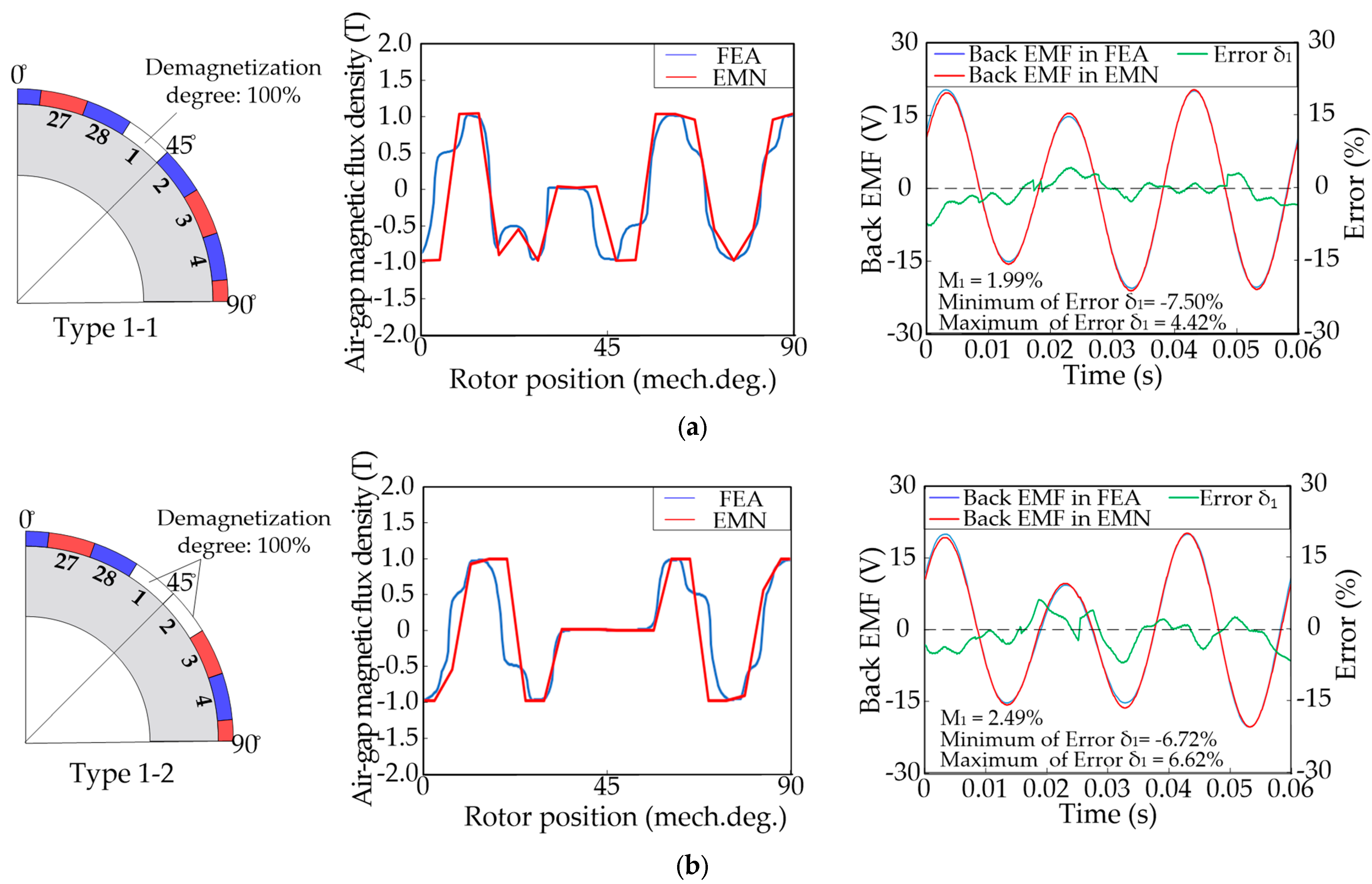
| Group 1 | Type 1-1 | 100% | 0% | 0% |
| Type 1-2 | 100% | 100% | 0% | |
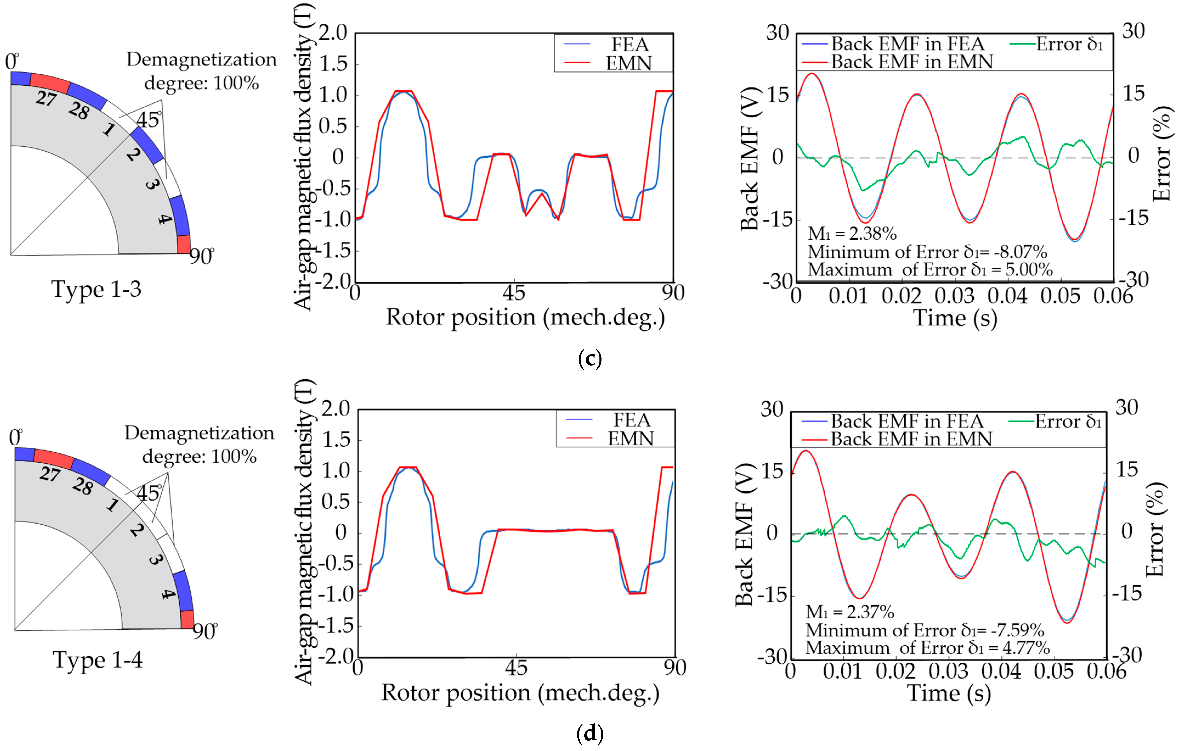
| Type 1-3 | 100% | 0% | 100% | |
| Type 1-4 | 100% | 100% | 100% | |
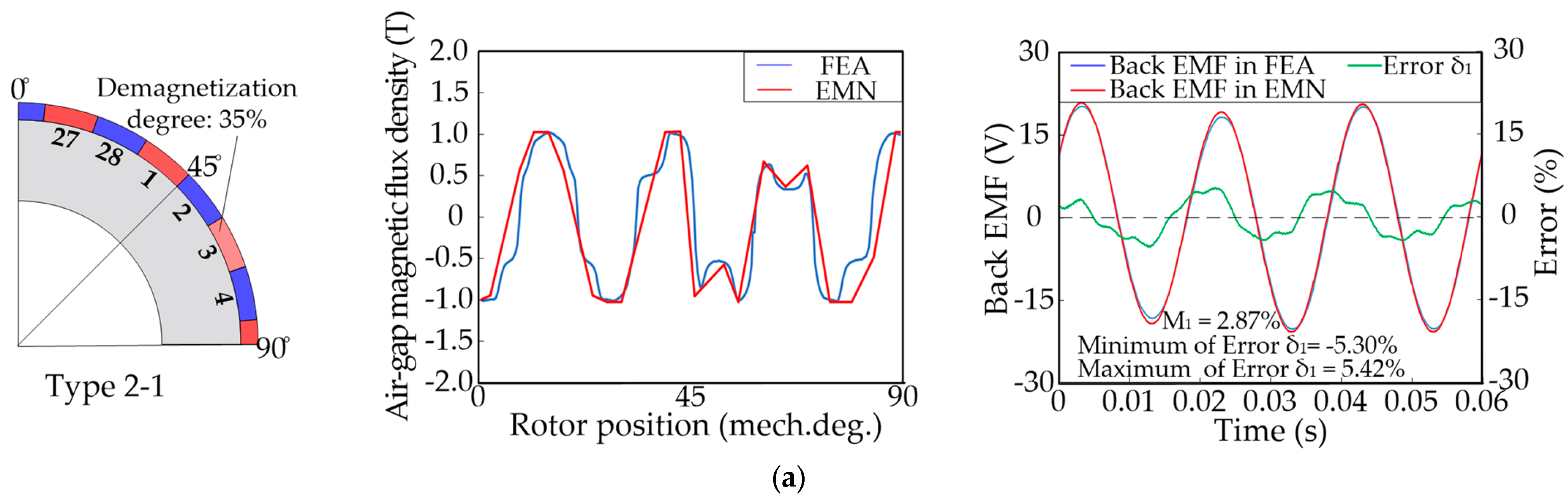
| Group 2 | Type 2-1 | 35% | 0% | 0% |
| Type 2-2 | 50% | 0% | 0% | |
| Type 2-3 | 65% | 0% | 0% | |
| Type 2-4 | 80% | 0% | 0% | |
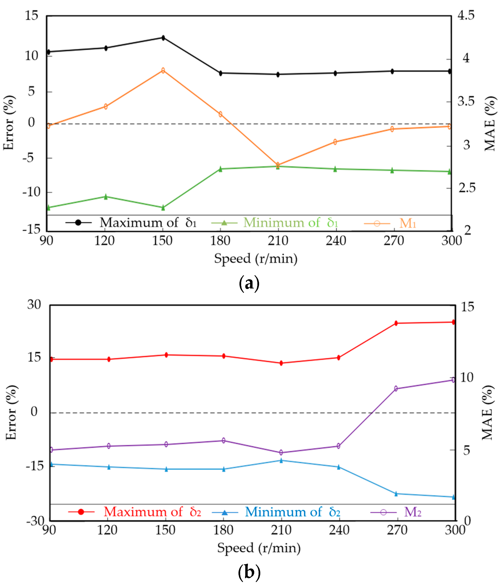
4.2. Result Comparison Analysis
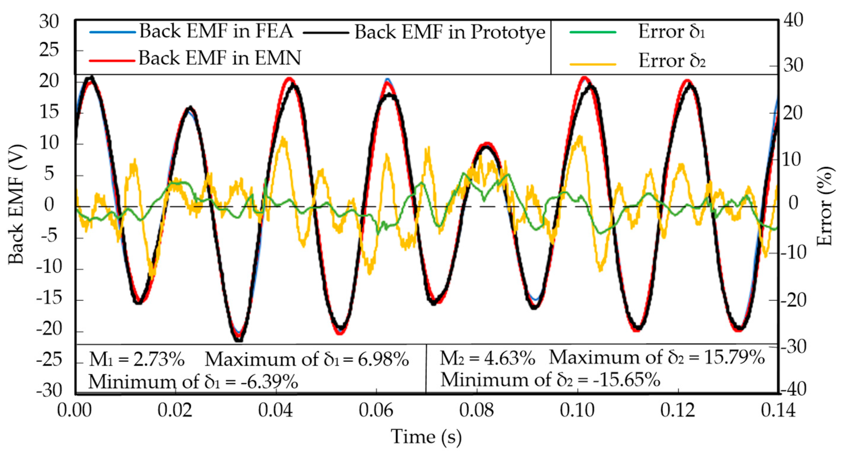
5. Experimental Verification
6. Conclusions
Author Contributions
Funding
Data Availability Statement
Conflicts of Interest
References
- Liu, J.; Li, X.; Yan, B.; Hua, W.; Wang, X. Electromagnetic Performance Analysis of a Field-Modulated Permanent Magnet Motor Using Improved Hybrid Subdomain Method. IEEE Trans. Energy Convers. 2023. Early Access. [Google Scholar] [CrossRef]
- Li, X.; Wei, Z.; Zhao, Y.; Wang, X.; Hua, W. Design and Analysis of Surface-Mounted Permanent-Magnet Field-modulation Machine for Achieving High Power Factor. IEEE Trans. Ind. Electron. 2023. Early Access. [Google Scholar] [CrossRef]
- Li, X.; Liu, S.; Wang, Q.; Yan, B.; Huang, Z.; Wang, K. Performance Investigation and Experimental Testing of a Stator-PM-Excitation Axial-Flux Magnetic Gear. IEEE Trans. Transport. Electrific. 2023, 9, 2593–2605. [Google Scholar] [CrossRef]
- Li, X.; Chau, K.; Cheng, M.; Kim, B.; Lorenz, R. Performance Analysis of a Flux-Concentrating Field-Modulated Permanent-Magnet Machine for Direct-Drive Applications. IEEE Trans. Magn. 2015, 51, 8104911. [Google Scholar] [CrossRef]
- Jing, L.; Liu, W.; Tang, W.; Qu, R. Design and Optimization of Coaxial Magnetic Gear with Double-Layer PMs and Spoke Structure for Tidal Power Generation. IEEE/ASME Trans. Mechatron. 2023. Early Access. [Google Scholar] [CrossRef]
- Jing, L.; Tang, W.; Wang, T.; Ben, T.; Qu, R. Performance Analysis of Magnetically Geared Permanent Magnet Brushless Motor for Hybrid Electric Vehicles. IEEE Trans. Transp. Electrific. 2022, 8, 2874–2883. [Google Scholar] [CrossRef]
- Zhao, H.; Liu, C.; Dong, Z.; Huang, R.; Li, X. Design and Optimization of a Magnetic-Geared Direct-Drive Machine with V-Shaped Permanent Magnets for Ship Propulsion. IEEE Trans. Transport. Electrific. 2022, 8, 1619–1633. [Google Scholar] [CrossRef]
- Jing, L.; Wang, T.; Tang, W.; Liu, W.; Qu, R. Characteristic Analysis of the Magnetic Variable Speed Diesel-Electric Hybrid Motor with Auxiliary Teeth for Ship Propulsion. IEEE/ASME Trans. Mechatron. 2023. Early Access. [Google Scholar] [CrossRef]
- Zhou, P.; Lin, D.; Xiao, Y.; Lambert, N.; Rahman, M. Temperature-Dependent Demagnetization Model of Permanent Magnets for Finite Element Analysis. IEEE Trans. Magn. 2012, 48, 1031–1034. [Google Scholar] [CrossRef]
- Woo, D.; Jeong, B. Irreversible Demagnetization of Permanent Magnet in a Surface-Mounted Permanent Magnet Motor with Overhang Structure. IEEE Trans. Magn. 2016, 52, 8102606. [Google Scholar] [CrossRef]
- Fernández, D.; Martinez, M.; Reigosa, D.; Guerrero, J.; Alvarez, C.; Briz, F. Permanent Magnets Aging in Variable Flux Permanent Magnet Synchronous Machines. IEEE Trans. Ind. Appl. 2020, 56, 2462–2471. [Google Scholar] [CrossRef]
- Kim, H.; Park, J.; Hur, J. Comparison Analysis of Demagnetization and Torque Ripple in Accordance with Freewheeling Current in PM BLDC Motor. IEEE Trans. Magn. 2015, 51, 8108204. [Google Scholar] [CrossRef]
- Chen, H.; Qu, R.; Li, J.; Li, D. Demagnetization Performance of a 7 MW Interior Permanent Magnet Wind Generator with Fractional-Slot Concentrated Windings. IEEE Trans. Magn. 2015, 51, 8205804. [Google Scholar] [CrossRef]
- Kang, D. Analysis of Vibration and Performance Considering Demagnetization Phenomenon of the Interior Permanent Magnet Motor. IEEE Trans. Magn. 2017, 53, 8210807. [Google Scholar] [CrossRef]
- Kim, K.; Kim, K.; Kim, H.; Lee, J. Demagnetization Analysis of Permanent Magnets According to Rotor Types of Interior Permanent Magnet Synchronous Motor. IEEE Trans. Magn. 2009, 45, 2799–2802. [Google Scholar] [CrossRef]
- Guo, L.; Wang, K.; Wang, T. Open-Circuit Fault Diagnosis of Three-Phase Permanent Magnet Machine Utilizing Normalized Flux-Producing Current. IEEE Trans. Ind. Electron. 2023. Early Access. [Google Scholar] [CrossRef]
- Lin, D.; Zhou, P.; Bracken, E. Generalized Algorithm to Deal with Temperature-Dependent Demagnetization Curves of Permanent Magnets for FEA. IEEE Trans. Magn. 2021, 57, 7402706. [Google Scholar] [CrossRef]
- Fu, W.; Ho, S. Dynamic Demagnetization Computation of Permanent Magnet Motors Using Finite Element Method with Normal Magnetization Curves. IEEE Trans. Appl. Supercond. 2010, 20, 851–855. [Google Scholar] [CrossRef]
- Zhang, J.; Jiang, Y.; Zhao, J.; Hua, W. An Improved Brushless Doubly Fed Generator with Interior PM Rotor for Wind Power Applications. IEEE Trans. Magn. 2019, 55, 8105506. [Google Scholar] [CrossRef]
- Bisschop, J.; Abdallh, A.; Sergeant, P.; Dupré, L. Identification of Demagnetization Faults in Axial Flux Permanent Magnet Synchronous Machines Using an Inverse Problem Coupled with an Analytical Model. IEEE Trans. Magn. 2014, 50, 8104804. [Google Scholar] [CrossRef]
- Verkroost, L.; De Bisschop, J.; Vansompel, H.; Belie, F.; Sergeant, P. Active Demagnetization Fault Compensation for Axial Flux Permanent-Magnet Synchronous Machines Using an Analytical Inverse Model. IEEE Trans. Energy Convers. 2020, 35, 591–599. [Google Scholar] [CrossRef]
- Bisschop, J.; Vansompel, H.; Sergeant, P.; Dupre, L. Demagnetization Fault Detection in Axial Flux PM Machines by Using Sensing Coils and an Analytical Model. IEEE Trans. Magn. 2017, 53, 8203404. [Google Scholar] [CrossRef]
- Gong, C.; Deng, F. Demagnetization Analysis of a Split-Tooth Concentrated-Winding Vernier Machine using Halbach-array-based Ferrite Magnets. In Proceedings of the 2021 IEEE International Electric Machines & Drives Conference (IEMDC), Hartford, CT, USA, 17–20 May 2021. [Google Scholar] [CrossRef]
- Li, L.; Fu, W.; Ho, S.; Niu, S.; Li, Y. A Quantitative Comparison Study of Power-Electronic-Driven Flux-Modulated Machines Using Magnetic Field and Thermal Field Co-Simulation. IEEE Trans. Ind. Electron. 2015, 62, 6076–6084. [Google Scholar] [CrossRef]
- Li, X.; Chau, K.; Wang, Y. Modeling of a Field-Modulated Permanent-Magnet Machine. Energies 2016, 9, 1078. [Google Scholar] [CrossRef]
- Tong, C.; Song, Z.; Bai, J.; Liu, J.; Zheng, P. Analytical Investigation of the Magnetic-Field Distribution in an Axial Magnetic-Field-Modulated Brushless Double-Rotor Machine. Energies 2016, 9, 589. [Google Scholar] [CrossRef]
- Oner, Y.; Zhu, Z.; Wu, L.; Ge, X.; Zhan, H.; Chen, J. Analytical On-Load Subdomain Field Model of Permanent-Magnet Vernier Machines. IEEE Trans. Ind. Electron. 2016, 63, 4105–4117. [Google Scholar] [CrossRef]
- Cao, D.; Zhao, W.; Ji, J.; Ding, L.; Zheng, J. A Generalized Equivalent Magnetic Network Modeling Method for Vehicular Dual-Permanent-Magnet Vernier Machines. IEEE Trans. Energy Convers. 2019, 34, 1950–1962. [Google Scholar] [CrossRef]
- Li, X.; Lu, K.; Zhao, Y.; Chen, D.; Yi, P.; Hua, W. Incorporating harmonic-analysis-based loss minimization into MPTC for efficiency improvement of FCFMPM motor. IEEE Trans. Ind. Electron. 2023, 70, 6540–6550. [Google Scholar] [CrossRef]
- Ostovic, V. A simplified approach to magnetic equivalent-circuit modeling of induction machines. IEEE Trans. Ind. Appl. 1988, 24, 308–316. [Google Scholar] [CrossRef]
- Cao, D.; Zhao, W.; Liu, T.; Wang, Y. Magneto-Electric Coupling Network Model for Reduction of PM Eddy Current Loss in Flux-Switching Permanent Magnet Machine. IEEE Trans. Ind. Electron. 2022, 69, 1189–1199. [Google Scholar] [CrossRef]
- Fleming, F.; Edrington, C. Real-Time Emulation of Switched Reluctance Machines via Magnetic Equivalent Circuits. IEEE Trans. Ind. Electron. 2016, 63, 3366–3376. [Google Scholar] [CrossRef]
- Ghods, M.; Gorginpour, H.; Bazrafshan, M.; Toulabi, M. Equivalent Magnetic Network Modeling of Dual-Winding Outer-Rotor Vernier Permanent Magnet Machine Considering Pentagonal Meshing in the Air-Gap. IEEE Trans. Ind. Electron. 2022, 69, 12587–12599. [Google Scholar] [CrossRef]
- Cao, D.; Zhao, W.; Ji, J.; Wang, Y. Parametric Equivalent Magnetic Network Modeling Approach for Multiobjective Optimization of PM Machine. IEEE Trans. Ind. Electron. 2021, 68, 6619–6629. [Google Scholar] [CrossRef]
- Li, X.; Xue, Z.; Zhang, L.; Hua, W. A Low-Complexity Three-Vector-Based Model Predictive Torque Control for SPMSM. IEEE Trans. Power Electron. 2021, 36, 13002–13012. [Google Scholar] [CrossRef]
- Li, X.; Xue, Z.; Yan, X.; Zhang, L.; Ma, W.; Hua, W. Low-Complexity Multivector-Based Model Predictive Torque Control for PMSM With Voltage Preselection. IEEE Trans. Power Electron. 2021, 36, 11726–11738. [Google Scholar] [CrossRef]


| Parameters | Value | Unit |
|---|---|---|
| Rated speed | 214 | r/min |
| Rated power | 250 | W |
| Phase voltage | 18 | V |
| Phase current | 2.3 | A |
| PM pole number of rotor | 28 | - |
| Number of stator tooth | 24 | - |
| Pole-pair number of armature winding | 10 | - |
| Number of turns per armature coil | 119 | - |
| Stack length | 60 | mm |
| Air-gap length | 1.5 | mm |
| Material of iron core | 35CS250 | - |
| Material of PMs | N38SH | - |
| Thickness of PM | 4 | mm |
| Inner radius of rotor | 25 | mm |
| Outer radius of rotor | 42 | mm |
| Inner radius of stator | 43.5 | mm |
| Outer radius of stator | 72 | mm |
| Thickness of stator yoke | 5 | mm |
| Width of stator tooth | 4 | mm |
| Terms | Symbol | Equations |
|---|---|---|
| Permeance of stator yoke-1 | ||
| Permeance of stator yoke-2 | ||
| Permeance of stator tooth-1 | ||
| Permeance of stator tooth-2 | ||
| Permeance of Leakage flux-1 | ||
| Permeance of Leakage flux-2 | ||
| Permeance of Leakage flux-3 | ||
| MMF source of stator tooth |
| Divided Grids | Error | Calculation Time |
|---|---|---|
| 1 | 23.24% | 10.26 s |
| 2 | 16.28% | 44.33 s |
| 3 | 10.30% | 74.04 s |
| 4 | 3.02% | 102.02 s |
| 5 | 2.33% | 282.45 s |
| 6 | 2.14% | 686.92 s |
| Terms | Symbol | Equations |
|---|---|---|
| Permeance of rotor yoke-1 | ||
| Permeance of rotor yoke-2 | ||
| Permeance of rotor yoke-3 | ||
| Permeance of PM | ||
| MMF source of PM |
| Thresholds | Error | Calculation Time |
|---|---|---|
| 0.25 | 9.87% | 212.56 s |
| 0.40 | 6.97% | 238.48 s |
| 0.55 | 3.26% | 262.24 s |
| 0.70 | 0.43% | 282.45 s |
| 0.85 | 0.14% | 302.45 s |
| 1.00 | 0% | 322.65 s |
| Value Interval of x | Equations |
|---|---|
| [0, ] | |
| [, ] | |
| [, 2π − ] | |
| [2π − , 2π − ] | 0 |
| [2π − , 2π] |
| Methods | Equations |
|---|---|
| Exponential | |
| Fourier | |
| Gaussian | |
| Power | |
| Rational | |
| Sum of Sin Functions | |
| Weibull |
| Methods | Comparative Terms | |
|---|---|---|
| The Number of Grids | Calculation Time | |
| FEA | 10,322 | 447 s |
| Proposed EMN | 352 | 102 s |
Disclaimer/Publisher’s Note: The statements, opinions and data contained in all publications are solely those of the individual author(s) and contributor(s) and not of MDPI and/or the editor(s). MDPI and/or the editor(s) disclaim responsibility for any injury to people or property resulting from any ideas, methods, instructions or products referred to in the content. |
© 2023 by the authors. Licensee MDPI, Basel, Switzerland. This article is an open access article distributed under the terms and conditions of the Creative Commons Attribution (CC BY) license (https://creativecommons.org/licenses/by/4.0/).
Share and Cite
Li, X.; Tan, Y.; Yan, B.; Zhao, Y.; Wang, H. Demagnetization Modeling and Analysis for a Six-Phase Surface-Mounted Field-Modulated Permanent-Magnet Machine Based on Equivalent Magnetic Network. Energies 2023, 16, 6099. https://doi.org/10.3390/en16166099
Li X, Tan Y, Yan B, Zhao Y, Wang H. Demagnetization Modeling and Analysis for a Six-Phase Surface-Mounted Field-Modulated Permanent-Magnet Machine Based on Equivalent Magnetic Network. Energies. 2023; 16(16):6099. https://doi.org/10.3390/en16166099
Chicago/Turabian StyleLi, Xianglin, Yingjie Tan, Bo Yan, Yujian Zhao, and Hao Wang. 2023. "Demagnetization Modeling and Analysis for a Six-Phase Surface-Mounted Field-Modulated Permanent-Magnet Machine Based on Equivalent Magnetic Network" Energies 16, no. 16: 6099. https://doi.org/10.3390/en16166099
APA StyleLi, X., Tan, Y., Yan, B., Zhao, Y., & Wang, H. (2023). Demagnetization Modeling and Analysis for a Six-Phase Surface-Mounted Field-Modulated Permanent-Magnet Machine Based on Equivalent Magnetic Network. Energies, 16(16), 6099. https://doi.org/10.3390/en16166099