Article

Effect of Rotating Channel Turning Section Clearance Size on Heat Transfer Characteristics of Supercritical Pressure Hydrocarbon Fuel

School of Energy Science and Engineering, Harbin Institute of Technology, Harbin 150001, China
*
Author to whom correspondence should be addressed.
Energies 2023, 16(16), 6051; https://doi.org/10.3390/en16166051
Submission received: 2 July 2023 / Revised: 3 August 2023 / Accepted: 16 August 2023 / Published: 18 August 2023
(This article belongs to the Section J1: Heat and Mass Transfer)

Abstract

:
For the problem of power generation turbine blade ablation in hypersonic vehicles, hydrocarbon fuel carried by the vehicle is used to cool the turbine blades. In order to fully utilize the cooling capacity of hydrocarbon fuel, the structure of the cooling channels needs to be optimized. In this study, a variable clearance hydrocarbon fuel cooling channel is applied for the first time to the rotating turbine blades of a hypersonic vehicle to enhance the heat transfer ability of hydrocarbon fuel. The effect of clearance size on the heat transfer performance of hydrocarbon fuel under rotating conditions is investigated. The accuracy of the calculations is verified by comparison with experimental data. The results of the study show that the heat transfer performance can be significantly improved by changing the clearance of the turning section. The clearance size 2.5 D channel has the highest thermal performance with a maximum improvement of 1.8 times. The law of change of thermal performance is affected by crossing the critical temperature point, as it is different before and after the crossing. Thermal performance changes from decreasing then increasing to increasing then decreasing as the clearance size increases for high rotation speed conditions as the temperature of the entrance straddles the critical temperature. The Nusselt number first increases and then decreases for all channels with different clearance sizes with an increasing rotational speed. The friction factor changes from first increasing and then decreasing to decreasing and then increasing as the clearance size increases for high rotation speed conditions as the temperature of the entrance straddles the critical temperature.

1. Introduction

At present, long range and long endurance are the main development goals of hypersonic vehicles. The electrical power requirements of hypersonic vehicles increase significantly when performing long-range missions [1]. In particular, the application of various new weapon systems, such as laser weapon systems, has put more stringent requirements on the vehicle’s power generation equipment. Since hypersonic vehicle engines use scramjet engines, which have no rotating parts, they are supplied with electricity by onboard batteries. Since electric power storage devices such as batteries cannot meet the requirements of long-duration cruise flight of hypersonic vehicles, new high-power power generation systems need to be developed. For subsonic vehicles, the engine is a compressor–turbine system, which can produce power or generate electricity through the rotation of compressor blades and turbine blades. Therefore, the electricity supply is more than adequate for subsonic vehicles. The focus of this paper is on the electricity supply of hypersonic vehicles. The authors of [2] investigated magnetohydrodynamic power generation devices for hypersonic vehicles. However, the technology of magnetohydrodynamic power generation devices is not mature and the mass is large, which prevents the realization of engineering applications. Li et al. [3] investigated the fuel steam turbine electricity generation device. It utilizes the fuel cracking gas to propel a turbine to do work, which in turn drives a generator to produce electricity. However, the fuel steam turbine power generation device is affected by the degree of fuel cracking as well as the flow rate, and the products of fuel cracking also affect the power generated by the turbine. Under constant flow conditions, the fuel steam turbine is unable to maintain a large power output for a long period of time. Its power output is unstable. The authors of [4] described and investigated the ram air turbine electricity generator. It utilizes the incoming air to push the turbine blades to do work, converting the kinetic energy of the air into mechanical energy, which in turn pushes the generator to produce electrical energy. Compared with fuel steam turbine power generators and magnetohydrodynamic power generators, air turbine power generators have the advantages of stable operation, simple structure and high power generation capacity, and are widely used in aircraft [4]. However, the high velocity of the hypersonic vehicle makes the incoming air temperature too high, which can lead to turbine blade ablation. As the Mach number of hypersonic vehicle flight increases further, the temperature of the incoming air becomes higher and higher. Therefore, cooling of the blades is required to prevent blade ablation. The only coolant available on hypersonic vehicles at this time is hydrocarbon fuel. The use of hydrocarbon fuel to cool the turbine blades allows the power generation turbine blades to withstand the impact of high temperatures so that material safety requirements can be met [5,6]. The feasibility of hydrocarbon fuel cooling of power generation turbine blades for hypersonic vehicles has been demonstrated in the literature [5].
Internal cooling is an important cooling method for turbine blades [7]. For typical air-cooled U-channels, the distribution of ribs has been investigated in depth [8,9,10,11,12,13]. The shape and clearance size of the air-cooled U-channel turning section can lead to changes in the pressure distribution in the channel and the flow characteristics of the second flow passage [14,15,16,17,18,19,20,21]. The change in the clearance size of the turning section under static conditions can improve the flow separation and reattachment of air, weakening the flow resistance of the channel, which in turn has an obvious impact on the TP of the U-shaped channel [19]. The installation of turning vanes in the turning section area also affects the pressure loss and heat exchange behavior of the channel. The turning vanes structure in the turning section region can significantly weaken the separation by air flow and the pressure loss in the channel, which in turn improves the flow state and thermal performance of the channel [22,23,24,25,26]. As can be seen from the above literature, the shape and clearance size of the turning section can have an obvious impact on the resistance to flow and thermal performance of the air-cooled U-channel. At present, most of the investigations on the clearance of the channel turning section are focused on the static conditions, where the cooling medium is air. So far, the effect of rotating channel turning section clearance on the flow resistance and thermal performance of hydrocarbon fuel has not been investigated.
Compared to air, the effects of temperature and pressure on the physical property of the fuel are more obvious. Therefore, when hydrocarbon fuel is used as the cooling medium to study the rotating channel turning section clearance effects, the comprehensive influence of the clearance of the turning section, the rotational additional force and the physical properties need to be considered. The hydrocarbon fuel in the stationary channel can cause changes to the flow state and temperature non-uniformity during the heating process due to the buoyancy force [27,28,29,30,31,32]. The channel cross-sectional size parameters and cross-sectional shape under static conditions affect the buoyancy effect, flow state and temperature variation. For rectangular channels, optimal aspect ratios exist to improve the cooling capacity of hydrocarbon fuels [33,34,35,36,37,38,39,40]. Therefore, when the hydrocarbon fuel is under rotating conditions and the channel cross-sectional shape and size parameters are also changed, the flow state, temperature distribution and thermal performance change significantly due to the comprehensive impact of the cross-sectional shape and the rotation induced rotational additional forces. Jiang and Lu et al. experimentally investigated the effect of rotational speed on the thermal exchange performance of the fuel [41,42]. The results of this experiment showed that the convective heat transfer coefficient increases with an increasing rotational speed. However, the maximum rotational speed of the experiment conducted by Jiang et al. was only 1500 rpm, and the pressure variation of the fuel was very small. At this point, the pressure gradient has little effect on the fuel. For studying the effect of rotational additional forces, the investigation of the thermal exchange performance of the fuel under high rotational speed conditions is necessary. For fuel-cooled turbine blades, the incoming high-temperature air can cause the hydrocarbon fuel to coke on the turbine blade surface if external cooling is used. Therefore, only internal cooling can be used for hydrocarbon fuel cooling turbine blades. The authors of [43] investigated the feasibility of using power generation turbines for hypersonic vehicles and analyzed the cooling problems faced by power generation turbines. The temperature changes before and after hydrocarbon fuel cooling of the turbine blade wall were also compared. The results showed that hydrocarbon fuels can significantly reduce the temperature of turbine blades.
Based on this, this research applies variable clearance hydrocarbon fuel cooling channels to the rotating power generation turbine blades of hypersonic vehicles. This paper focuses on the effect of U-channel turning section clearance size parameters under rotating conditions on the friction factor and thermal performance of supercritical pressure hydrocarbon fuel. The comprehensive effects of fuel property, turning section clearance and rotational state on heat transfer performance are investigated in depth, and the optimal clearance size of the turning section to enhance the thermal performance of hydrocarbon fuel in the rotating channel is investigated, to provide new ideas for further development of enhanced cooling structures for supercritical pressure hydrocarbon fuel under rotating conditions.

2. Numerical Calculation Details

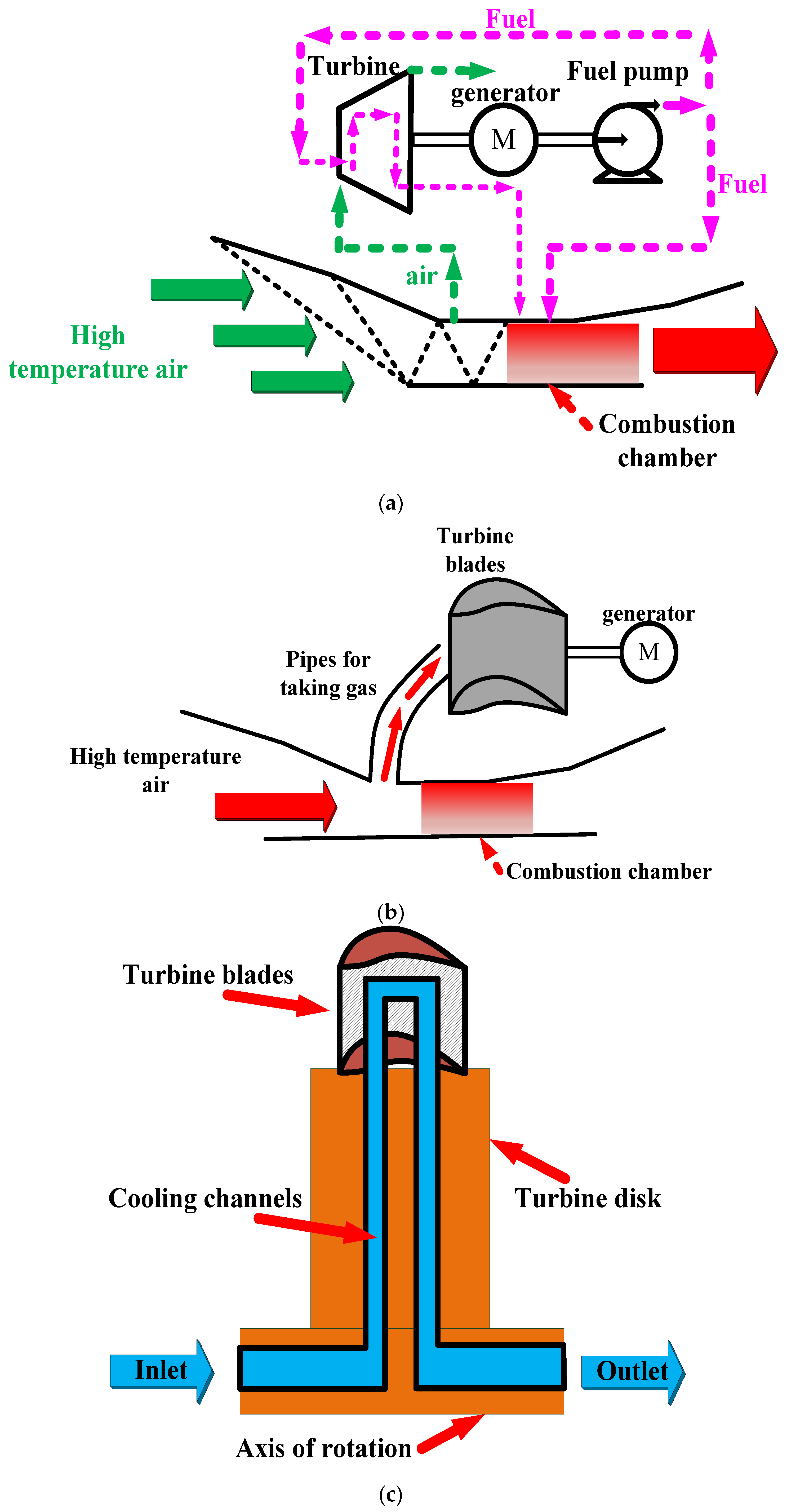
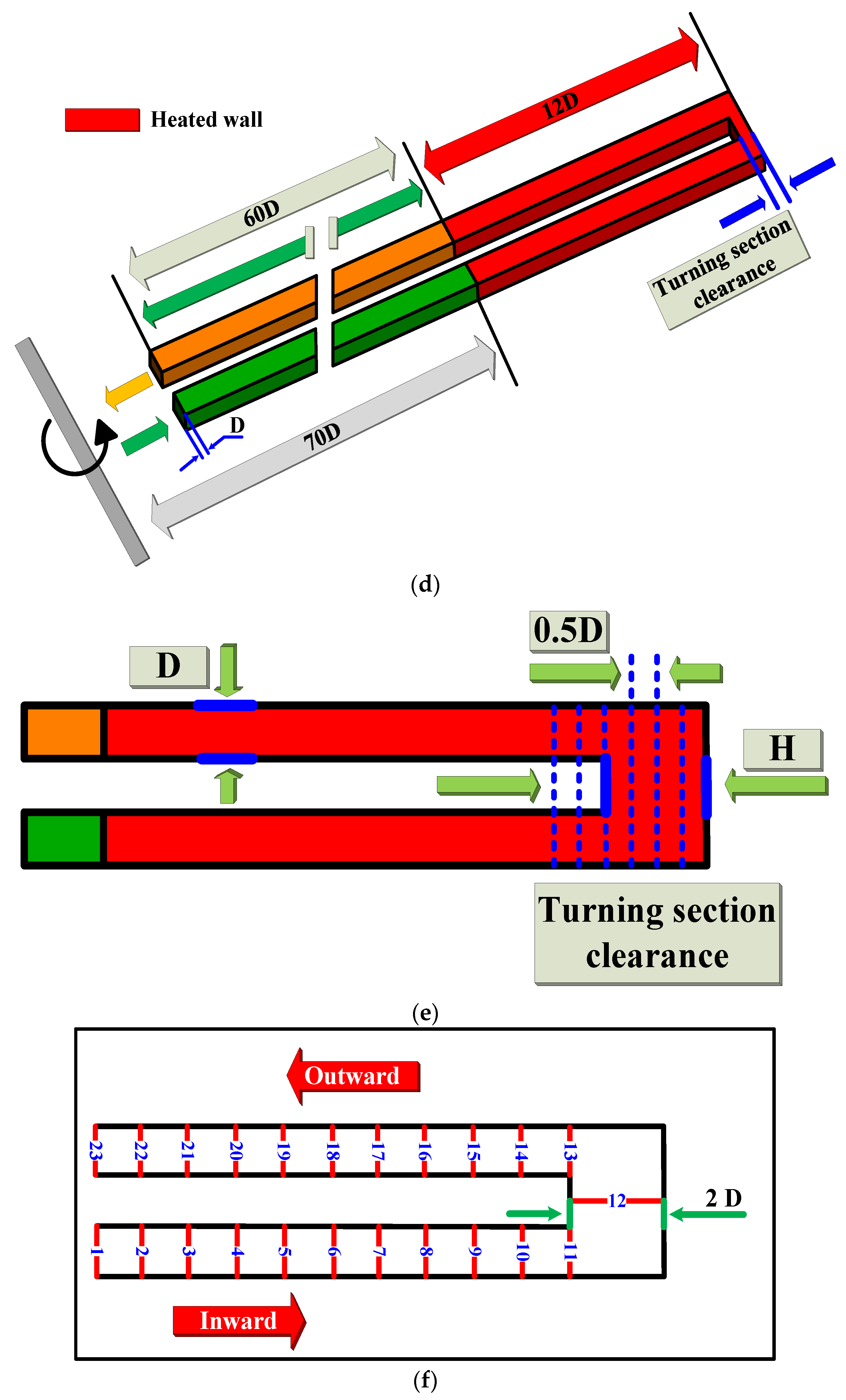
2.1. Computational Model Details

The hypersonic vehicle ram air power turbine system is shown in Figure 1a. Figure 1b shows the turbine intake pipe. When the hypersonic vehicle flies at a high Mach number, the air temperature exceeds the safety limit of the turbine blade material, so the turbine blade needs to be cooled. In this research, the cooling channel is constructed based on the hypersonic vehicle power generation turbine blade size [8,43]. The channel hydraulic diameter D is 1 mm. Figure 1c,d illustrates the cooling channels. Figure 1c illustrates the location of the U-shaped cooling channels. As can be seen in Figure 1c, the hydrocarbon fuel in the cooling channel flows through the turbine blades and turbine disk, which in turn cools the turbine blades. The models with different turning section clearances are shown in Figure 1e. For more detailed understanding of the pressure, temperature and physical property distribution along the flow direction in the heated section, the channels need to be named. Figure 1f shows the cross-sectional names of the heating portion along the direction of fuel flow. In Figure 1f, 1–11 and 13–23 are cross sections every 1 mm apart. Figure 1g shows the names of the individual walls of the heating section. Turning section clearance sizes are shown in Table 1.

2.2. Boundary Conditions and Physical Properties Calculation Method

Since the critical temperature of n-decane is 617.7 K [44], the cooling channel inlet temperatures were set to 610 K and 630 K, respectively, in order to obtain the heat transfer characteristics of the supercritical pressure hydrocarbon fuel during the process of transiting the critical temperature point in the rotating state. In order to prevent cracking reactions and carbon deposition in hydrocarbon fuels, the heating section was provided at a constant temperature. Therefore, a constant wall temperature of 700 K was used for heating the wall. Since the critical pressure of n-decane is 2.11 MPa [44], the outlet pressure was set to 4 MPa in order to prevent a phase transition. The mass flow was set to 3 g/s based on the flow requirements of the hypersonic vehicle power generation turbine cooling channel [5,43]. This mass flow meets the cooling requirements. In order to ensure the safety of the turbine blade material, the rotational speed was set to 0–40,000 rpm, which meets the requirements of the power generation turbine blade for hypersonic vehicles [3,6].
Since n-decane is an important component of hydrocarbon fuels, it was chosen for study [44]. All references to hydrocarbon fuels in the following paragraphs refer to n-decane. Therefore, the accurate calculation of the physical property of hydrocarbon fuels is extremely important for the analysis of heat transfer characteristics. Since the physical properties of n-decane can be accurately calculated by the P-R equation and the method proposed by Chung et al [45,46]. Therefore, the P-R equation and the method of Chung et al. were adopted to calculate the n-decane physical property in this paper [45,46]. The governing equations for hydrocarbon fuel flow heat transfer are shown in the literature [47].

2.3. Turbulence Model Selection and Mesh Details

The generation and development of the hydrocarbon fuel vortex structure and the influence of rotational effects on the flow structure are all related to the choice of turbulence model in the numerical calculation. The heat transfer characteristics of hydrocarbon fuels under rotating conditions were investigated in the literature [48] using the SST turbulence model. Their results show that the SST turbulence model can accurately predict the heat transfer characteristics of hydrocarbon fuels. Related studies have shown that the SST turbulence model can provide a relatively accurate calculation of the hydrocarbon fuel flow states and thermal exchange regularities inside smooth and ribbed channels [35,36,37,49,50,51,52]. The experimental data of Jiang et al. [41] was used to validate the SST turbulence model. The boundary conditions were the same as in the literature [41]. Figure 2a shows the validation results. The distance from the first measured section to the axis of rotation was 138 mm. From Figure 2a, it can be observed that the calculated results agree well with the experimental data in the literature [41] at rotational speeds of 500 rpm or 1500 rpm, respectively. From the above results, the SST turbulence model can obtain the law of thermal exchange of hydrocarbon fuel under rotating conditions more accurately.
In this paper, ICEM 2019 software is adopted to generate the structural mesh of the variable turning section clearance cooling channel. ICEM software is a relatively full-featured pre-processing software. It has versatile mesh handling for fast mesh generation. It can provide high quality model meshes for CFX 2021 software. The cooling channel with a clearance of 2D in the turning section is selected for verification. Figure 2b shows the grid of channel. The grid independence verification is shown in Figure 2c. It can be observed from Figure 2c that the difference in the Nusselt number of channels is smaller after the grid node number exceeds 1 million. Therefore, the model with the grid nodes number of 2,932,551 was selected for numerical calculation in this paper. The y+ of the cooling channel was 0.35, which satisfies the demands of the SST turbulence model.

2.4. Data Reduction

The calculation formula of convective heat transfer coefficient under rotating conditions is shown in (1).
h = q / ( ( T heat-out T heat-in ) / ln ( ( T w T heat-in ) / ( T w T heat-out ) ) )
The calculation formula of Re is shown in (2).
Re = ρ heat-in V heat-in D / μ heat-in
The equations for Nu and Nu0 are shown in (3) and (4), respectively [53].
Nu = hD / λ b
Nu 0 = 0.023 Re 0.8 Pr 0.4
The equations for f and f0 are shown in (5) and (6), respectively [53].
f = ( p / ( 0.5 ρ b U b 2 ) ) D / L
f 0 = 0.079 Re 0.25
The thermal performance is calculated as shown in (7).
TP = ( Nu / Nu 0 ) / ( f / f 0 ) 1 / 3

3. Results and Discussions

3.1. Effect of Clearance Size on Flow Velocity Distribution

The pressure and temperature in the channel increase obviously with an increasing rotation speed, which is shown in Figure 3. The maximum pressure increase is 6.7 times and the maximum temperature increase is 4.3% for 40,000 rpm of rotation speed compared to static conditions. The high-pressure gradient leads to drastic changes in physical property, which in turn influence the flow law of the fuel. The ρ and μ of the fuel increase substantially with an increasing rotational speed from Figure 4. The maximum increase in density is 47.3% and the maximum increase in dynamic viscosity is 1.9 times for 40,000 rpm rotational speed compared to static conditions. The significant increases in ρ and μ under rotating conditions cause the flow resistance to increase, in turn causing the velocity of flow to decrease.
It can be seen from Figure 5 that the velocity increases and then decreases from 25,000 rpm to 40,000 rpm. High rotational speeds lead to high centrifugal forces, which in turn lead to high pressures. High pressures increase the density and dynamic viscosity of hydrocarbon fuels, causing an increase in resistance, which in turn leads to a decrease in velocity. However, the hydrocarbon fuel is deflected due to the Coriolis force, which increases the velocity of the hydrocarbon fuel. Therefore, the fuel velocity increases and then decreases. When it is less than 25,000 rpm, the change in hydrocarbon fuel physical properties due to rotation at this point is small. The effects of density and dynamic viscosity are less than those of the Coriolis force, so the velocity rises gradually.
It can be observed from Figure 6 that the hydrocarbon fuel has three different flow directions in the region of the turning section. Streamline 1 mainly impacts wall Top 1, then impacts wall Top 2 when it enters the second flow channel. Streamline 2 mainly impacts walls Top 1 and Top 2 and the second flow channel wall Outside 2, then flows into the second flow channel. Streamline 3 mainly impacts the first flow channel wall Inside 1. When the clearance size is 0.5 D, the impingement effect of streamline 3 on wall Inside 1 is obvious. The smaller clearance size leads to a significantly higher hydrocarbon fuel velocity in the region of the turning section. The impingement effect of streamline 1 and streamline 2 on walls Top 1, Top 2, Inside 2 and Outside 2 is more obvious. Therefore, when the clearance size is 0.5 D, the h of the channel is higher. With an increase in the clearance size from 0.5 D to 2 D, the impingement effect of streamline 3 on the inner wall in the first flow channel outlet position decreases. The clearance size increases, resulting in a significant decrease in fuel velocity in the turning section. At the same time, the impingement effect of streamline 1 and streamline 2 on walls Inside 2 and Outside 2 close to the area of the turning section is significantly reduced. Therefore, the h of the channel decreases with an increase of the clearance size from 0.5 D to 2 D. With the clearances increasing from 2 D to 3 D, the velocity in the area of the turning section near the trailing surface increases significantly. Combining Figure 5 and Figure 6, it can be seen that as the clearance size increases, the first channel outlet position moves to the heated section inlet location, which causes the velocity close to the region of the trailing surface near the first channel outlet position to increase. As the clearance size increases, the impingement effect of streamline 1 and streamline 2 on walls Top 2, Inside 2 and Outside 2 close to the area of the turning section increases significantly. Therefore, with an increase of the clearance size from 2 D to 3 D, the h of the channel increases. In summary, the h of the channel first decreases and then increases as the clearance size increases.

3.2. Effect of Clearance Size and Temperature of Inlet on f

From Figure 7, it can be observed that at 630 K entrance temperature, the f first decreases and then increases in the range of 0–20,000 rpm and 20,000–40,000 rpm rotational speed, respectively, with an increasing clearance size. This causes the TP of the channel to first increase and then decrease with an increasing clearance size in this range of rotation speeds. The impact of temperature of the inlet on the channel friction factor is small in the 0–10,000 rpm rotation speed range. The 2.5 D channel achieves the lowest value of friction factor at 610 K, 20,000 rpm. This results in the highest TP of the 2.5 D channel at 610 K inlet temperature and 20,000 rpm rotation speed.
For an entrance temperature of 610 K and a speed of rotation >25,000 rpm, the f increases and then decreases as the gap size increases. The phenomenon is caused by the fact that with an increasing clearance size, the channel pressure difference first increases and then decreases. This causes the TP of the channel to decrease and then increase as the clearance size increases at 610 K inlet temperature and at rotational speeds >25,000 rpm.
As can be seen in Figure 7, the f of the channel changes in the completely opposite regularity before and after the entrance temperature crosses the critical temperature as the clearance size increases for high rotation speed conditions. Its f changes from first increasing and then decreasing to decreasing and then increasing. The channel f is maximally improved by 51 times for the 610 K entrance temperature compared to the 630 K entrance temperature.

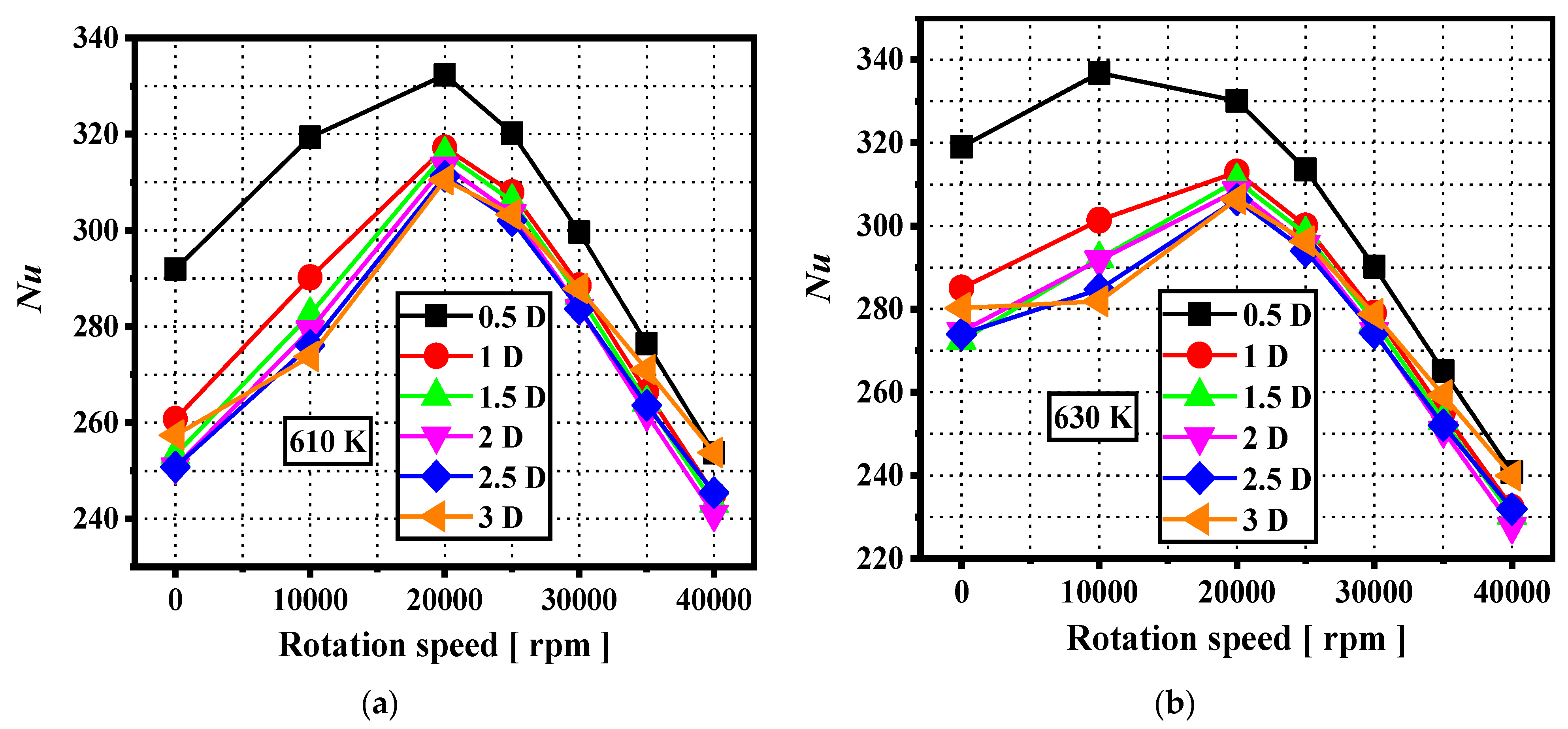
3.3. Effect of Clearance Size and Inlet Temperature on Heat Exchange Performance

It can be obviously observed from Figure 8 that the Nu first increases and then decreases with an increase in the rotation speed for different clearance size channels. Under low rotational speed conditions, the fuel is deflected due to the Coriolis force, which enhances the heat transfer capacity near the trailing surface of the first channel. Therefore, the channel Nu rises with increasing rotational speed at low rotational speed conditions. The increase in physical properties causes a decrease in the velocity of the hydrocarbon fuel for high rotation speed conditions, which results in a weakening of the impingement effect of the hydrocarbon fuel and therefore a decrease in the Nu. The range of rotational speeds corresponding to the maximum Nu obtained for different clearance size channels at different inlet temperature conditions is 10,000–20,000 rpm. The Nu of the channel can be significantly improved by reducing the clearance size when the clearance size is less than 1 D.
It can be observed from Figure 9 that the TP of the clearance size 2.5 D channel acquires the maximum value. The clearance size 2.5 D channel has a maximum TP improvement of 1.8 times. The clearance size 2.5 D channel has the lowest coefficient of friction, which results in the highest TP. At 610 K entrance temperature, 0 rpm and 20,000 rpm, the channel TP first rises and then falls with an increasing clearance size due to the friction factor. For rotation speeds >30,000 rpm, the TP of the channel first drops and then rises as the clearance size increases due to the friction factor. For the 630 K entrance temperature, the channel TP first increases and later decreases for the majority of rotational speed conditions as the clearance size is increased. The reason for this phenomenon is that the channel friction factor first drops and then rises as the clearance size is increased under most rotational speed conditions. The maximum value of TP is obtained in the clearance size range of 1.5 D to 2.5 D for most rotational speed conditions. At high rotation speed conditions, compared to the 610 K entrance temperature, the TP of the channel at 630 K is maximally improved by 2.3 times.
There are few current studies on the heat transfer characteristics of hydrocarbon fuel near the critical temperature point under rotating conditions, and thus a lack of measures to enhance the heat exchange capacity of hydrocarbon fuel in the rotating channel. Therefore, in this paper, a variable turn section clearance channel is proposed to enhance the thermal performance of the channel. After the analysis, the optimum turning section clearance was obtained. The thermal performance of the optimal turning section clearance channel is increased by a maximum of 1.8 times. Furthermore, the effect of the clearance of the turning section on the friction coefficient was obtained, and the change law of the friction coefficient is summarized. This provides some theoretical guidance for the study of hydrocarbon fuel cooling channels.

4. Conclusions

In this research, a cooling channel with variable turning section clearance size is established. The effects of parameters such as the clearance size of the turning section, rotation speed, fuel physical properties and entrance temperature on the friction factor are analyzed. The effect of the clearance size of the channel turning section on the thermal transfer performance of hydrocarbon fuel under rotation conditions is investigated. The conclusions are as follows:
(1)
Thermal performance can be significantly improved by changing the clearance of the turning section. The clearance size 2.5 D channel obtains the highest value of thermal performance. The thermal performance of the clearance size 2.5 D channel is maximally improved by 1.8 times.
(2)
The law of change of thermal performance before and after crossing the critical temperature point is completely opposite. The channel thermal performance changes from decreasing then increasing to increasing then decreasing as the clearance size increases for high rotational speed conditions as the temperature of the entrance straddles the critical temperature of the hydrocarbon fuel. The thermal performance is maximally improved by 2.3 times for the 630 K entrance temperature compared to the 610 K entrance temperature.
(3)
The law of change of friction coefficient before and after crossing the critical temperature point is completely opposite. Its friction coefficient changes from first increasing and then decreasing to decreasing and then increasing. The channel friction factor is maximally improved by 51 times for the 610 K entrance temperature compared to the 630 K entrance temperature.
(4)
The Nusselt number first increases and then decreases for all channels with different clearance sizes with an increasing rotational speed. When the clearance size is less than 1 D, the Nusselt number of the channel can be significantly improved by reducing the clearance size. The Nusselt number maximum is achieved in the range of rotational speeds from 10,000 rpm to 20,000 rpm for all clearance size channels.

Author Contributions

Conceptualization, M.D. and H.H.; methodology, M.D.; software, M.D.; validation, M.D. and H.H.; investigation, M.D.; resources, H.H.; writing—original draft preparation, M.D.; writing—review and editing, M.D. and H.H.; visualization, M.D. All authors have read and agreed to the published version of the manuscript.

Funding

This research was funded by the National Natural Science Foundation of China (51876048).

Data Availability Statement

Not applicable.

Acknowledgments

The authors would like to thank the editor and the reviewers for their helpful comments and suggestions.

Conflicts of Interest

The authors declare no conflict of interest.

Nomenclature

Dhydraulic diameter [mm]
Ttemperature [K]
hconvective heat transfer coefficient [W/m2/K]
ppressure difference [Pa]
qheat flux [W/m2]
NuNusselt number
ReReynolds number
ffriction factor
PrPrandtl number
Greek symbols
ρdensity [kg/m3]
μdynamic viscosity [Pa·s]
λthermal conductivity [W/m/K]
Subscripts
heat-ininlet of heating section
heat-outoutlet of heating section
bbulk value
wwall
Abbreviations
TPthermal performance

References

  1. Zhang, D.; Qin, J.; Feng, Y.; Ren, F.; Bao, W. Performance evaluation of power generation system with fuel vapor turbine onboard hydrocarbon fueled scramjets. Energy 2014, 77, 732–741. [Google Scholar] [CrossRef]
  2. Macheret, S.; Shneider, M.; Miles, R. Magnetohydrodynamic Power Extraction from Cold Hypersonic Airflows with External Ionizers. J. Propuls. Power 2002, 18, 424–431. [Google Scholar] [CrossRef]
  3. Li, H.; Qin, J.; Jiang, Y.; Zhang, D.; Cheng, K.; Bao, W.; Huang, H. Experimental and theoretical investigation of power generation scheme driven by thermal cracked gaseous hydrocarbon fuel for hypersonic vehicle. Energy Convers. Manag. 2018, 165, 334–343. [Google Scholar] [CrossRef]
  4. Saad, M.M.M.; Mohd, S.; Zulkafli, M.F. A survey on the use of ram air turbine in aircraft. Aip. Conf. Proc. 2017, 1831, 020048. [Google Scholar]
  5. Sun, H.; Qin, J.; Huang, H.; Yan, P. Investigation of hydrocarbon fuel rotating flow considering the variation of physical properties. Int. J. Heat Mass Transf. 2019, 142, 118372. [Google Scholar] [CrossRef]
  6. Sun, H.; Qin, J.; Huang, H.; Yan, P. Numerical simulation of flow and heat transfer in a square rotating U-duct using hydrocarbon fuel. ASME J. Heat Transf. 2019, 141, 031701. [Google Scholar] [CrossRef]
  7. Han, J.-C. Turbine Blade Cooling Studies at Texas A&M University: 1980–2004. J. Thermophys. Heat Transf. 2006, 20, 161–187. [Google Scholar]
  8. Al-Hadhrami, L.; Han, J.-C. Effect of rotation on heat transfer in two-pass square channels with five different orientations of 45° angled rib turbulators. Int. J. Heat Mass Transf. 2003, 46, 653–669. [Google Scholar] [CrossRef]
  9. Qiu, L.; Deng, H.; Sun, J.; Tao, Z.; Tian, S. Pressure drop and heat transfer in rotating smooth square U-duct under high rotation numbers. Int. J. Heat Mass Transf. 2013, 66, 543–552. [Google Scholar] [CrossRef]
  10. Xu, G.; Li, Y.; Deng, H. Effect of rib spacing on heat transfer and friction in a rotating two-pass square channel with asymmetrical 90-deg rib turbulators. Appl. Therm. Eng. 2015, 80, 386–395. [Google Scholar] [CrossRef]
  11. Wang, L.; Wang, S.; Wen, F.; Zhou, X.; Wang, Z. Heat transfer and flow characteristics of U-shaped cooling channels with novel wavy ribs under stationary and rotating conditions. Int. J. Heat Mass Transf. 2018, 126, 312–333. [Google Scholar] [CrossRef]
  12. Singh, P.; Ji, Y.; Ekkad, S.V. Experimental and numerical investigation of heat and fluid flow in a square duct featuring criss-cross rib patterns. Appl. Therm. Eng. 2018, 128, 415–425. [Google Scholar] [CrossRef]
  13. Liou, T.; Chang, S.; Chan, S. Effect of rib orientation on thermal and fluid-flow features in a two-pass parallelogram channel with abrupt entrance. Int. J. Heat Mass Transf. 2018, 116, 152–165. [Google Scholar] [CrossRef]
  14. Nakayama, H.; Hirota, M.; Fujita, H.; Yamada, T.; Koide, Y. Fluid flow and heat transfer in two-pass smooth rectangular channels with different turn clearances. ASME J. Turbomach. 2006, 128, 772–785. [Google Scholar] [CrossRef]
  15. Hirota, M.; Fujita, H.; Syuhada, A.; Araki, S.; Yoshida, T.; Tanaka, T. Heat/mass transfer characteristics in two-pass smooth channels with a sharp 180-deg turn. Int. J. Heat Mass Transf. 1999, 42, 3757–3770. [Google Scholar] [CrossRef]
  16. Syuhada, A.; Hirota, M.; Fujita, H.; Araki, S.; Yanagida, M.; Tanaka, T. Heat (mass) transfer in serpentine flow passage with rectangular cross-section. Energy Convers. Manag. 2001, 42, 1867–1885. [Google Scholar] [CrossRef]
  17. Hirota, M.; Fujita, H.; Tanaka, A.; Araki, S.; Tanaka, T. Local heat (mass) transfer characteristics in rectangular ducts with a sharp 180-degree turn. Energy Convers. Manag. 1997, 38, 1155–1168. [Google Scholar] [CrossRef]
  18. Wang, T.-S.; Chyu, M.K. Heat convection in a 180-deg turning duct with different turn configurations. J. Thermophys. Heat Transf. 1994, 8, 595–601. [Google Scholar] [CrossRef]
  19. Pape, D.; Jeanmart, H.; von Wolfersdorf, J.; Weigand, B. Influence of the 180 Bend Geometry on the Pressure Loss and Heat Transfer in a High Aspect Ratio Rectangular Smooth Channel; ASME Paper No. GT2004-53753; ASME: New York, NY, USA, 2004. [Google Scholar]
  20. He, P.; Mader, C.A.; Martins, J.R.; Maki, K.J. Aerothermal optimization of a ribbed U-bend cooling channel using the adjoint method. Int. J. Heat Mass Transf. 2019, 140, 152–172. [Google Scholar] [CrossRef]
  21. Saha, K.; Acharya, S. Effect of Bend Geometry on Heat Transfer and Pressure Drop in a Two-Pass Coolant Square Channel for a Turbine. J. Turbomach. 2012, 135, 021035. [Google Scholar] [CrossRef]
  22. Wu, B.; Yang, X.; Liu, Z.; Feng, Z. Effects of novel turning vanes on pressure loss and tip-wall heat transfer in an idealized U-bend channel. Int. Commun. Heat Mass Transf. 2020, 121, 105072. [Google Scholar] [CrossRef]
  23. Yan, H.; Luo, L.; Zhu, P.-M.; Du, W.; Wang, S. Effects of varied bend turning vanes on flow control and heat transfer performance in a smooth twopass channel. Int. Commun. Heat Mass Transf. 2022, 135, 106044. [Google Scholar] [CrossRef]
  24. Xie, G.; Zhang, W.; Sunden, B. Computational analysis of the influences of guide ribs/vanes on enhanced heat transfer of a turbine blade tip-wall. Int. J. Therm. Sci. 2012, 51, 184–194. [Google Scholar] [CrossRef]
  25. Guo, Z.; Rao, Y.; Li, Y.; Wang, W. Experimental and numerical investigation of turbulent flow heat transfer in a serpentine channel with multiple short ribbed passes and turning vanes. Int. J. Therm. Sci. 2021, 165, 106931. [Google Scholar] [CrossRef]
  26. Lei, J.; Su, P.; Xie, G.; Lorenzini, G. The effect of a hub turning vane on turbulent flow and heat transfer in a four-pass channel at high rotation numbers. Int. J. Heat Mass Transf. 2016, 92, 578–588. [Google Scholar] [CrossRef]
  27. Sun, X.; Meng, H.; Zheng, Y. Asymmetric heating and buoyancy effects on heat transfer of hydrocarbon fuel in a horizontal square channel at supercritical pressures. Aerosp. Sci. Technol. 2019, 93, 105358. [Google Scholar] [CrossRef]
  28. Sun, X.; Meng, H. Large eddy simulations and analyses of hydrocarbon fuel heat transfer in vertical upward flows at supercritical pressures. Int. J. Heat Mass Transf. 2021, 170, 120988. [Google Scholar] [CrossRef]
  29. Sun, F.; Li, Y.; Manca, O.; Xie, G. An evaluation on the laminar effect of buoyancy-driven supercritical hydrocarbon fuel flow and heat transfer characteristics. Int. J. Heat Mass Transf. 2019, 142, 118414. [Google Scholar] [CrossRef]
  30. Wen, J.; Huang, H.; Jia, Z.; Fu, Y.; Xu, G. Buoyancy effects on heat transfer to supercritical pressure hydrocarbon fuel in a horizontal miniature tube. Int. J. Heat Mass Transf. 2017, 115, 1173–1181. [Google Scholar] [CrossRef]
  31. Zhu, J.Q.; Tao, K.H.; Tao, Z.; Qu, L. Heat transfer degradation of buoyancy involved convective RP-3 hydrocarbon fuel in vertical tubes with various diameters under supercritical pressure. Appl. Therm. Eng. 2019, 163, 114392. [Google Scholar] [CrossRef]
  32. Fu, Y.C.; Wen, J.E.; Tao, Z.; Xu, G.Q.; Huang, H.R. Experimental research on convective heat transfer of supercritical hydrocarbon fuel flowing through U-turn tubes. Appl. Therm. Eng. 2017, 116, 43–55. [Google Scholar] [CrossRef]
  33. Jiang, Y.; Xu, Y.; Qin, J.; Zhang, S.; Chetehouna, K.; Gascoin, N.; Bao, W. The flow rate distribution of hydrocarbon fuel in parallel channels with different cross section shapes. Appl. Therm. Eng. 2018, 137, 173–183. [Google Scholar] [CrossRef]
  34. Jiang, Y.; Xu, Y.; Zhang, S.; Chetehouna, K.; Gascoin, N.; Qin, J.; Bao, W. Parametric study on the distribution of flow rate and heat sink utilization in cooling channels of advanced aero-engines. Energy 2017, 138, 1056–1068. [Google Scholar] [CrossRef]
  35. Zhang, S.; Feng, Y.; Zhang, D.; Jiang, Y.; Qin, J.; Bao, W. Parametric numerical analysis of regenerative cooling in hydrogen fueled SCRamjet engines. Int. J. Hydrogen Energy 2016, 41, 10942–10960. [Google Scholar] [CrossRef]
  36. Zhang, S.; Qin, J.; Xie, K.; Feng, Y.; Bao, W. Thermal behavior inside SCRamjet cooling channels at different channel aspect ratios. J. Propuls. Power 2016, 32, 57–70. [Google Scholar] [CrossRef]
  37. Zhang, S.; Cui, N.; Xiong, Y.; Feng, Y.; Qin, J.; Bao, W. Effect of channel aspect ratio on chemical recuperation process in advanced aeroengines. Energy 2017, 123, 9–19. [Google Scholar] [CrossRef]
  38. Guo, Y.; Yang, Z.; Jiang, L.; Liu, Z.; Bi, Q. Convective heat transfer characteristics of supercritical hydrocarbon fuel in small non-circular cross-section channels. In Proceedings of the 11th AIAA/ASME Joint Thermophysics and Heat Transfer Conference, Atlanta, GA, USA, 16–20 June 2014. [Google Scholar]
  39. Cheng, Z.; Tao, Z.; Zhu, J.; Wu, H. Diameter effect on the heat transfer of supercritical hydrocarbon fuel in horizontal tubes under turbulent conditions. Appl. Therm. Eng. 2018, 134, 39–53. [Google Scholar] [CrossRef]
  40. Guo, Y.; Bi, Q.; Liu, Z.; Yang, Z.; Jiang, L. Experimental investigation on thermal-hydraulic characteristics of endothermic hydrocarbon fuel in 1 mm and 2 mm diameter mini-channels. Appl. Therm. Eng. 2017, 122, 420–428. [Google Scholar] [CrossRef]
  41. Jiang, P.; Lu, Z.; Guo, Y.; Zhu, Y. Experimental investigation of convective heat transfer of hydrocarbon fuels at supercritical pressures within rotating centrifugal channel. Appl. Therm. Eng. 2018, 147, 101–112. [Google Scholar] [CrossRef]
  42. Lu, Z.; Zhu, Y.; Guo, Y.; Jiang, P. Experimental Investigation of Convective Heat Transfer of Supercritical Pressure Hydrocarbon Fuel in a Horizontal Section of a Rotating U-Duct. J. Heat Transf. 2019, 141, 101702. [Google Scholar] [CrossRef]
  43. Sun, H.; Qin, J.; Li, H.; Huang, H.; Yan, P. Research of a combined power and cooling system based on fuel rotating cooling air turbine and organic Rankine cycle on hypersonic aircraft. Energy 2019, 189, 116183. [Google Scholar] [CrossRef]
  44. Qin, J.; Zhang, S.; Bao, W.; Zhou, W.; Yu, D. Thermal management method of fuel in advanced aeroengines. Energy 2012, 49, 459–468. [Google Scholar] [CrossRef]
  45. Kim, S.-K.; Choi, H.-S.; Kim, Y. Thermodynamic modeling based on a generalized cubic equation of state for kerosene/LOx rocket combustion. Combust. Flame 2012, 159, 1351–1365. [Google Scholar] [CrossRef]
  46. Poling, B.E.; Prausnitz, J.M.; O’connell, J.P. The Properties of Gases and Liquids, 5th ed.; McGraw-Hill Professional: New York, NY, USA, 2001. [Google Scholar]
  47. Feng, Y.; Qin, J.; Bao, W.; Yang, Q.; Huang, H.; Wang, Z. Numerical analysis of convective heat transfer characteristics of supercritical hydrocarbon fuel in cooling panel with local flow blockage structure. J. Supercrit. Fluids 2014, 88, 8–16. [Google Scholar] [CrossRef]
  48. Dong, M.; Feng, Y.; Wu, K.; Qin, J.; Huang, H. Heat transfer characteristics of supercritical pressure hydrocarbon fuels in rotating trapezoidal channels. Int. Commun. Heat Mass Transf. 2023, 140, 106556. [Google Scholar] [CrossRef]
  49. Zhao, Y.; Wang, Y.; Liang, C.; Zhang, Q.; Li, X. Heat transfer analysis of n-decane with variable heat flux distributions in a mini-channel. Appl. Therm. Eng. 2018, 144, 695–701. [Google Scholar] [CrossRef]
  50. Li, Y.; Xie, G.; Zhang, Y.; Ferla, P.; Sunden, B. Flow Characteristics and Heat Transfer of Supercritical n-decane in Novel Nested Channels for Scramjet Regenerative Cooling. Int. J. Heat Mass Transf. 2021, 167, 120836. [Google Scholar] [CrossRef]
  51. Li, X.; Qin, J.; Zhang, S.; Cui, N.; Bao, W. Effects of micro-ribs on the thermal behavior of transcritical n-decane in asymmetric heated rectangular mini-channels under near critical pressure. J. Heat Transf. 2018, 140, 122402. [Google Scholar] [CrossRef]
  52. Li, X.; Zhang, S.; Qin, J.; Bao, W. Parametric analysis on the thermal behavior of cracking hydrocarbon fuel flow inside asymmetry heated cooling channels with micro-ribs. Int. J. Heat Mass Transf. 2020, 160, 120154. [Google Scholar] [CrossRef]
  53. Ravi, B.V.; Singh, P.; Ekkad, S.V. Numerical investigation of turbulent flow and heat transfer in two-pass ribbed channels. Int. J. Therm. Sci. 2017, 112, 31–43. [Google Scholar] [CrossRef]
Figure 1. Turbine blade cooling channel parameters. (a) Hypersonic vehicle power generation turbine diagram. (b) Schematic diagram of the turbine intake. (c) Location of U-shaped cooling channels. (d) Channel structure diagram. (e) Turning section clearance diagram. (f) Name of each cross section of heating portion. (g) Name of each wall of the heating portion.
Energies 16 06051 g001aEnergies 16 06051 g001bEnergies 16 06051 g001c
Figure 2. Turbulence model and mesh details. (a) Comparison of temperature change trend of numerical calculation results and experimental data density. (b) Model grid schematic. (c) The effect of grid nodes number on Nusselt number.
Energies 16 06051 g002aEnergies 16 06051 g002b
Figure 3. Fuel pressure and temperature distribution in the channel. (a) Pressure; (b) temperature.
Energies 16 06051 g003
Figure 4. Distribution of fuel properties in the channel. (a) Density; (b) dynamic viscosity.
Energies 16 06051 g004
Figure 5. First flow channel velocity distribution curve.
Energies 16 06051 g005
Figure 6. Fuel streamline distribution at inlet temperature 610 K. (a) Model; (b) 0.5 D, 40,000 rpm; (c) 1 D, 40,000 rpm; (d) 2 D, 40,000 rpm; (e) 2.5 D, 40,000 rpm; (f) 3 D, 40,000 rpm.
Energies 16 06051 g006aEnergies 16 06051 g006b
Figure 7. Friction factor variation curve. (a) 0 rpm; (b) 10,000 rpm; (c) 20,000 rpm; (d) 25,000 rpm; (e) 40,000 rpm.
Energies 16 06051 g007
Figure 8. Nusselt number variation curves at 610 K and 630 K. (a) 610 K; (b) 630 K.
Energies 16 06051 g008
Figure 9. Distribution of thermal performance of channels with different clearance sizes. (a) 0 rpm; (b) 10,000 rpm; (c) 20,000 rpm; (d) 25,000 rpm; (e) 30,000 rpm; (f) 35,000 rpm.
Energies 16 06051 g009
Table 1. Turning section clearance size parameters.
Model Clearance ParametersTurning Section Clearance
H0.5 D
1 D
1.5 D
2 D
2.5 D
3 D
Disclaimer/Publisher’s Note: The statements, opinions and data contained in all publications are solely those of the individual author(s) and contributor(s) and not of MDPI and/or the editor(s). MDPI and/or the editor(s) disclaim responsibility for any injury to people or property resulting from any ideas, methods, instructions or products referred to in the content.

