Article

Experimental Investigation on Gasoline—Water Mixture Fuel Impingement Preparation Method and Spray Characteristics with High Injection Temperatures and Pressures

1
School of Automotive Studies, Tongji University, Shanghai 201800, China
2
Energy Department, Politecnico di Torino, 10129 Turin, Italy
3
United Automotive Electronic Systems Co., Ltd., Shanghai 200100, China
*
Author to whom correspondence should be addressed.
Energies 2023, 16(16), 6026; https://doi.org/10.3390/en16166026
Submission received: 12 July 2023 / Revised: 14 August 2023 / Accepted: 15 August 2023 / Published: 17 August 2023
(This article belongs to the Topic Advanced Engines Technologies)

Abstract

:
Gasoline–water mixed injections are of great interest because of their advantages for reduced manufacturing costs and improved atomization, with the potential to alleviate engine detonation and reduce emissions. In this work, based on the principle of impinging flow, a real-time gasoline–water mixture preparation system for internal combustion engines was designed and the preparation system performance was compared with the standard swirl mixing technique. An image processing method was established to quantify the uniformity of the prepared mixture. Based on the flash-boiling spray flash-boiling spray experiment, the spray characteristics of different gasoline–water mixtures were analyzed under different injection temperatures (30–160 °C) and pressures (5–15 MPa). The experiments showed that the impinging pressure was the main factor affecting the emulsification performance of the real-time gasoline–water mixture, and that the proposed real-time mixing system could produce a stable gasoline–water emulsion. For temperatures in the 30–160 °C range, the flash-boiling spray flash-boiling spray experiments showed that the spray penetration distance first decreases and then increases with the injection temperature, while the spray angle shows an opposite trend. The turning point corresponded to the flash-boiling point of each gasoline–water mixture.

1. Introduction

The increasing energy demand, which is due to the vigorous development of the world economy, has brought about a tougher energy issue. According to the world energy outlook released by British Petroleum, even under the background of electrification, oil will continue to occupy the largest share of the energy structure (31.2%) in the 2020s. By 2050, oil is expected to account for a significant part of the transportation energy demand, and the demand of oil in highway transportation will be still large. In particular, China’s energy demand will continue to grow, and the extent of China’s energy crisis is severe [1,2]. A new engine technology, which could simultaneously enhance engine thermal efficiency and meet the stringent future emission policy for transportation, is urgently required.
Researchers, employing either experimental or numerical approaches [3,4], are focusing on many aspects of the gasoline engine to improve its performance, by means of the development of new control strategies [5,6,7,8], or by improving the engine hardware, including the fuel injection system [9], the turbocharging/supercharging system, or by means of design strategies like downsizing or downspeeding. Combining turbocharging/supercharging technology with downsizing guarantees that an engine has better power and fuel-economy properties [10]. However, with the rise in the boost level, the knock tendency [11,12,13] and even super knock tendency can also occur, which have an irreversible impact on engine reliability [14,15]. Compared to the normal knock, super knock has a higher in-cylinder pressure amplitude (in-cylinder pressures are beyond 10 MPa). In view of its destructive power, super knock is the main obstacle for gasoline engines to continue to increase power and reduce fuel consumption. Because of the transient nature and contingency of super knock, it is very difficult to deepen its mechanism and to develop a robust control method [16,17]. Effective measures to control the super knock intensity should be designed starting from these two perspectives: to reduce the conditions of its generation as much as possible and to decrease its intensity by controlling the kinetics of ignition and by accelerating the flame propagation speed after ignition. The traditional control methods of suppressing knock and super knock are the increasing equivalence ratio and delaying the spark advance, but these means sacrifice thermal efficiency. Thus, a new engine technology, which could suppress knock or super knock and improve engine thermal efficiency, would be valuable.
Water is a substance with a large latent heat of evaporation and stable chemical reaction characteristics. Introducing water into the combustion chamber as a working medium and using the characteristics of water evaporation and heat absorption to significantly reduce the temperature in the cylinder flow can effectively optimize the combustion phase and reduce the knock tendency [18,19,20,21,22,23]. Water injection technology, therefore, has great potential in improving thermal efficiency and in reducing emissions.
A gasoline–water mixed injection is considered to be a special water injection technology for internal combustion engines, which can not only improve thermal efficiency, but also reduce emissions. Compared with separate water port or direct injection, on the one hand, a gasoline–water mixed injection can be realized without major modification of the engine [24], which can alleviate the problem of cylinder wall wetting caused by a pure water spray [25]; on the other hand, the flash-boiling spray of the high temperature gasoline–water mixture can also be used to improve the atomization quality of the fuel, accelerate the formation of the air–fuel–water mixture and improve combustion. Xie [26] used the constant volume bomb to measure the atomization of a gasoline–water mixture in a flash–boiling state: the experiments showed that, under flash–boiling conditions, the gasoline–water mixture has an enlarged spray cone angle and reduced particle sizes. Zhou [27] studied the flash–boiling mechanism of multi-component fuels: the experimental results showed that the components with the highest saturated vapor pressure primarily affected the spray quality. Yan [28], by analyzing the flash-boiling spray of a two-component mixture, found that the spray quality could be improved dramatically by adjusting the latent heat of vaporization of the liquid constituents and by changing the mixture composition. Senda [29,30] conducted different research on flash-boiling spray: the influence of fuel superheat on the spray characteristics of the spray had a decisive effect. When the fuel superheat was the same, the spray parameters, such as spray penetration and cone angle, pertaining to distinct fuels became very similar.
The traditional preparation method of a gasoline–water mixture consists of emulsifying substances using emulsifier and emulsifying equipment [31,32]. Although this method can easily improve the emulsifying effect and mixture stability time by changing the emulsifier, it still cannot meet the needs of long-distance transportation, and the impact of the emulsifier on the engine component life or on engine emissions is difficult to evaluate. The gasoline–water mixing mode without emulsifier mainly relies on high-speed colloid mill, ultrasonic emulsification, high-pressure homogenizer, high-shear homogenizer or other equipment for mechanical mixing, which cannot be installed on the vehicle [33]. At present, there is an urgent need for a small and efficient real-time gasoline–water mixing equipment to meet the requirements of vehicle applications.
In the present work, an innovative real-time gasoline–water mixing method, based on the high-pressure impinging flow, is presented, and the spray characteristics of the generated mixture are explored for different injection pressure values, and a wide range of fuel temperatures, even beyond the flash-boiling temperature.

2. The Real Time Gasoline–Water Preparation Principle and Test

The principle of the impinging flow between liquids is shown in Figure 1. Each liquid flow forms a narrow high-speed jet, and a high-pressure turbulent region is formed in the central impact region, where large enough collision and shear forces are generated. In this process, the fluid particles continuously penetrate from one liquid to the other along opposite directions and, after several oscillations, the axial velocity disappears, and the impact area forms a collision mixed liquid [34]. The collision preparation process no longer needs emulsifier, which reduces the manufacturing costs, eliminates the effects of the emulsifier on the engine and can remove the experimental uncertainty caused by the emulsifier in the engine tests. Furthermore, a real-time mixing system designed by the impinging stream technology solves the problem of the gasoline–water stratification caused by long-time placement.
In Figure 2a, the bench for the mixture preparation is represented. The pressure supply system consists of two nitrogen cylinders (items 1), two pressure reducing valves (2), two pressure gauges (3) and two gas–liquid booster pumps (4), which compress gasoline (12) and water (11). The function of the pressure supply system is to provide a sufficiently high pressure level for gasoline–water collision, so that gasoline and water can fully collide and mix. The injection control system is composed of a time-relay (10), solenoid valves (5), which allow for injection, and a switch (14). The function is to control the timing and duration of the gasoline–water injection and collision through the actuation of the solenoid valves.
A real-time filled gasoline–water parallelepipedal tank (13) was designed, with a length, width and height of 62 mm, 40 mm and 20 mm, respectively, in order to collect the mixture. In Figure 2b, a detailed scheme of the collision system (item 9 in Figure 2a) is reported: the gasoline and water inlets both adopt a two-stage section design. The first section, featuring a diameter equal to 6.4 mm, is that of the external high-pressure pipe and is commanded by solenoid valve (5) for either gasoline and water; the diameter of the second section is reduced to 0.2–0.3 mm in order to provide a sufficiently high injection speed of gasoline and water. Downstream of the collision zone between water and gasoline, a mixing pipe with a diameter of 2 mm conveys the mixture to a tank (13 in Figure 2a).
In order to analyze the influence of the pressure on the gasoline–water mixture preparation, five impinging pressure levels (Pimp) were analyzed, namely, 5 MPa, 10 MPa, 15 MPa, 20 MPa and 25 MPa. These pressure levels were obtained at the delivery of the gas–liquid booster pumps (4) by exploiting the delivery pressure (PN) of the N2 bottles, which was measured by means of sensors (3). The pressurization ratio R of the gas–liquid booster pumps was equal to 64:1; therefore, one has Pimp = PN·R and PN was regulated by means of pressure-reducing valves (2).
The proportion of gasoline and water was controlled by regulating the size of the gasoline and water second sections. The diameter of the second section of the gasoline pipe (metering diameter) could be either 0.2 or 0.3 mm, whereas that of the second section of the water pipe was fixed at 0.2 mm. If the gasoline-to-water metering-to-diameter ratio is 1:1, the outlet flow volumetric ratio is nearly 1:1. Instead, if the gasoline-to-water metering-to-diameter ratio is 3:2, the corresponding outlet flow volumetric ratio is 9:4. If the gasoline–water volumetric ratio is 1:1, the gasoline accounts for 50% of the whole mixture volume, identified by G50; instead, if the gasoline–water volumetric ratio is 9:4, the gasoline accounts for about 70% of the whole mixture volume, which is indicated by acronym G70.
In the classic emulsions obtained with a mechanical device, the mixture color approaches to milky white [26]. Figure 3a shows the gasoline–water blend, obtained with a gasoline-to-water metering-to-diameter ratio 1:1 by means of the impingement method for Pimp = 25 MPa: the gasoline–water mixed emulsion is uniform and milky white. As a microscope cannot observe and analyze the mixture in real-time, a new method that can quickly judge the mixing state is needed. In order to better quantify the mixing difference between the collision mixing device (impingement method) and a traditional mechanical stirring/mixing device (also referred to as swirl method), an image method was used in this paper. It analyzes the stable time and homogeneity of the gasoline–water mixture and has the advantages of being able to quantify the mixing degree, requiring a simple observation and low manufacturing costs. The contoured red area in Figure 3a is the image-processing area: Red, Green and Blue are the basic colors used in the method to generate all the others. The larger the values of R, G and B (the maximum value for each basic color is 255), the closer the liquid mixture is to the white.
In Table 1, the calculated relative standard deviation is shown, based on the values of R, G and B, for the mixture obtained using the impingement method. The relative standard deviation, expressed as a percentage, is given by the ratio of the standard deviation to the average value of the considered quantity. In particular, by choosing 10 sub-areas inside the image-processing area, the R, G, B standard deviations, which were assumed as an index of the mixture homogeneity, can be evaluated. In particular, the overall RGB relative standard deviation is given by the average of relative standard deviations for the single R, G, and B color channels. A microscope photo of G70 using the swirl method, reported in Figure 3b, shows a satisfactory mixing quality of the swirl technique; such a mixture was assumed as a benchmark to assess the image-processing technique for different mixture methods. Table 1 reports R, G, B and RGB relative standard deviations for a G50 swirl mixture, the G70 swirl mixture (benchmark) and a G70 impingement mixture. All the mixture methods present satisfactory values of the relative standard deviation; in particular, the G50 and G70 swirl mixtures, which were obtained with a traditional mixing technique, presented comparable relative standard deviation values that are in line with those of the G70 mixture obtained by means of the impingement technique. Therefore, the image processing technique is consistent, and the impingement-based method has a good potential to replace the swirl-based one.
For the emulsions obtained using the impingement method, the settleability was also evaluated. The R, G and B mean values of the gasoline–water mixture in the image processing area are reported in Table 2 with reference to a volumetric ratio 9:4 (G70) and to Pimp = 25 MPa for the unsettled and settled conditions (after standing for 5 h).
The mean values pertaining to the gasoline–water mixture after a 5 h settling were R = 134, G = 143 and B = 143, respectively. Compared with the newly mixed liquid (unsettled gasoline–water), the R, G and B mean values were strongly reduced; therefore, an obvious stratification occurred, as is also shown in Figure 3c for the G70 mixture. As the color of the mixed liquid became more and more uneven and the gasoline and water were stratified, an evident increase in the standard deviations of R, G and B can be noticed in Table 2.
Figure 4a reports the standard deviations, calculated with the RGB technique, as functions of Pimp, for the mixture ratio 1:1. As can be seen, the standard deviations decline with an increase in the pressure; that is, the gasoline–water mixture becomes more and more uniform with an increase in Pimp. Referring to Figure 4b, between 20 MPa and 25 MPa of impingement pressure, the total RGB deviation of the mixture with the gasoline–water mixing ratio at 1:1 was generally better than that with the gasoline–water mixing ratio at 9:4; this means that the former had a more uniform mixing and, hence, was more suitable for impinging mixing devices at high pressures.
Table 3 reports the stability time of the two gasoline–water mixtures, obtained at different impingement pressures. The stability time is defined as the hours after which a clear layer becomes evident, i.e., when the water and gasoline start to be separated. As can be inferred from Table 3, the stability time increases with the impingement pressure up to 5 h when Pimp = 20 MPa; however, any further pressure increment does not lead to an augmentation in the stability time.

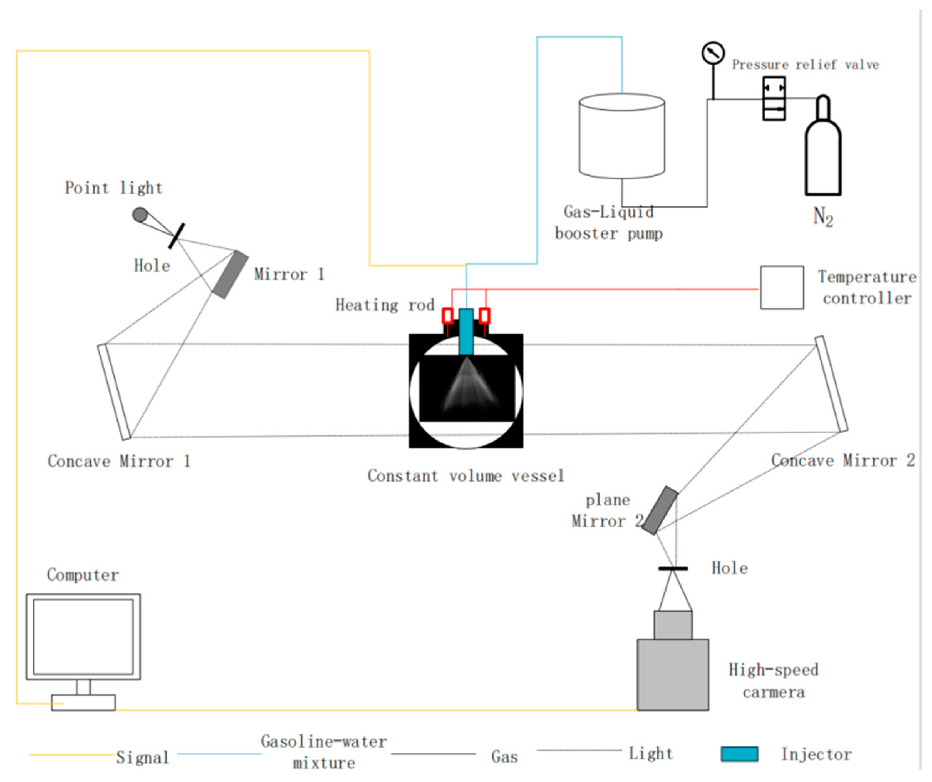
3. The Experimental System for Spray Analysis

The spray experimental equipment is shown in Figure 5. A synchronous measuring system for high-speed Schlieren was realized. The gasoline–water-mixture-spray test bench consisted of a constant-volume vessel (at atmospheric pressure), an optical system, a fuel injection system, a high-speed camera (phantom V7.3) and a computer. The high-speed camera has a shooting speed of 11,000 frames per second and a maximum resolution of 800 × 600 dpi. The fuel injection system consists of a nitrogen cylinder, a booster pump that compresses the gasoline–water mixture by using high-pressure N2, a 5-hole GDI injector and a fixture equipped with a heating rod. The injector is surrounded by the heating rod to elevate the injector temperature and, consequently, the fuel one. Therefore, the mixture injection temperature can be elevated from 30 °C to 160 °C. The injector and the high-speed camera were triggered simultaneously, and the spray process was recorded. The gasoline–water mixture was prepared according to the proposed gasoline–water mixing equipment described in Figure 2, with Pimp = 25 MPa. Both G50 and G70 were considered and the pure gasoline and the pure water were labeled with G100 and G0, respectively. The test conditions are detailed in Table 4.
Figure 6 shows the method used for processing the data from the original images. It is based on Open CV, which is an open-source image-processing library containing a variety of algorithms in the field of computer vision and image processing. Background subtraction was used to obtain Figure 6b from the original picture represented in Figure 6a. The basic idea of background subtraction is to detect moving objects by using the grey difference between the current frame image and the corresponding pixels of the background image. If the grey value difference between the pixel of the current frame image and the corresponding pixel of the background image is small, this pixel is considered as the background pixel; instead, if the grey value difference between the pixel of the current frame image and the pixel of the background image is large, this pixel is considered as detectable. Using a suitable threshold value is very important to distinguish the background and the spray structure data. This suitable value was selected with an iterative procedure. For a tentative threshold value, contours were extracted and compared with the original figures. If the matching was satisfactory, the tested value became the fixed one; otherwise, the procedure started again with another tentative value [26]. The spray outer edge and spray area could be correctly recognized, as shown in Figure 6c. Then, the contour of the object was extracted, as shown in Figure 6d, and the macroscopic parameters of the spray could be finally calculated.
The spray penetration and cone angle were defined, as shown in Figure 7. The spray penetration distance defines the vertical distance from the spray hole to the tip of the gasoline–water mixture spray and was used to characterize the infiltration capacity of the mixture. In the definition of the spray cone angle, the nozzle is taken as the apex and the angle is formed with the two rays at the outermost maximum edges of the spray.

4. The Spray Experimental Results and Discussion

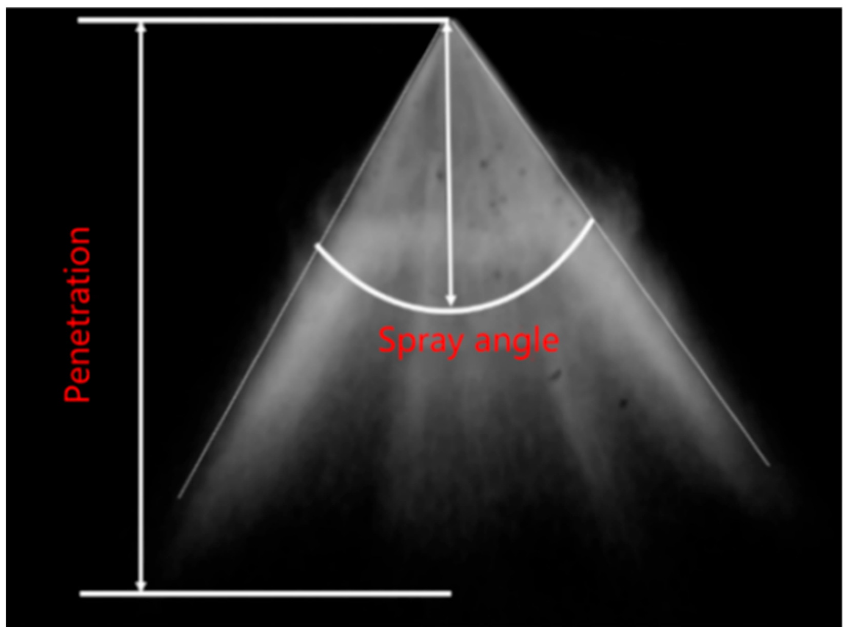
4.1. Spray Morphology

The experimental optical results pertaining to different proportions of the gasoline–water mixture sprays are shown in Figure 8, for different injection temperatures and at an injection pressure of Pj = 5 MPa. The smoothness of the spray edge increases progressively, moving from G100 to G0, up to 110 °C. In fact, the edge of the water spray is regular and wrinkle-free at lower temperatures than 110 °C. As either the water content in the mixture decreases or the temperature exceeds 110 °C, the edges of the spray gradually become more marked and/or more irregular. The irregular edges are caused by the different evaporation tendencies between water and gasoline. At a low temperature, i.e., 30 °C, both water and gasoline do not reach boiling point. However, since the gasoline tends to evaporate easily, its edges are more irregular than water. The reason for this is that the gasoline includes some low boiling-temperature fuels like pentane (boiling temperature 36 °C) and hexane (boiling temperature 70 °C).
In general, as the temperature increases, the injected emulsion of gasoline and water generally gets closer to the axis and the spray width decreases. If one considers the pure water injection (G0), the downstream sides of the spray keep the same smooth edges as the upstream ones up to 110 °C with no evident deformation of the spray pattern (there is poor air entrainment), but, as soon as the temperature reaches 120 °C, the edges of the bottom part of the spray become irregular. Instead, referring to the pure gasoline spray, a progressive reduction in the spray angle occurs starting from 80 °C: in fact, gasoline had already started to evaporate adequately and the expanded volume of gasoline vapor leads to a spray morphology change, which induces a larger entrainment of air into the spray. The presence of water in the mixture allows a more stable spray structure up to a higher temperature value. This can be inferred from the results pertaining to the G70 and G50 mixtures. In particular, if G70 is considered, at a temperature of 100 °C, the entrainment phenomenon becomes obvious, and at 120 °C, the pure gasoline spray shape is strongly deformed in its downstream part and the edges of both sides are not well defined. For the G50 case, the spray shape was kept at 100 °C and 110 °C.
Figure 9 plots the spray penetration time history for the two different preparation methods, at a temperature of 140 °C and for Pj = 5 MPa. The spray penetration of the impinging emulsion was comparable with the one prepared by the traditional swirl-method blend. It can be concluded that the gasoline–water emulsion prepared by the proposed real-time method can replace the mixture prepared by traditional mechanical stirring.

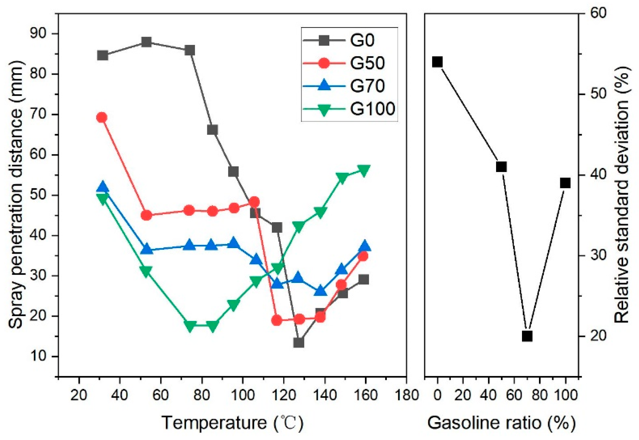
4.2. Effect of Injection Temperature on Penetration Distance

The left part of Figure 10 shows the effect of the injection temperature on the spray penetration at Pj = 5 MPa. The reported spray penetrations refer to 1.5 ms after the injection was carried out, because the plumes were fully developed and represented the spray characteristics. The spray penetration, referring to G0, G50, G70 and G100, decreased up to the flash-boiling point and then increased. The spray penetration of G0 was larger than that of G100 below the flash-boiling temperatures, due to the higher density and viscosity of water with respect to gasoline. In fact, a higher inertia and dynamic viscosity promoted the spray axial evolution, since it could resist the gas–liquid relative movement more without deformation and breakup [35], while the opposite occurred above the flash-boiling temperatures. When the injection temperature of the mixture increases, the viscosity of either a pure liquid flow or an emulsion decreases [26]; therefore, the spray penetration decreases as the injection temperature rises [36]. If the mixture is close to the boiling point of water, flash boiling occurs at the outlet of the nozzle: the water in the mixture starts to evaporate, and the overall mass decreases quickly, leading to a reduction in the inertial force and in the momentum, thus resulting in a sharp decrease in the spray penetration distance. With a further temperature increment, the additional momentum caused by the flash-boiling phenomenon accelerates again the spray along the axial direction, leading to an increment in penetration [37]. In fact, when the flash-boiling condition is overwhelmed, the spray’s distinct plumes collapse into a single one characterized by an enhanced axial momentum [38]. These effects cause the spray to lose its regular cone shape.
Due to the higher volatility and lower flash-boiling temperature of gasoline compared to water, the penetration distance of pure gasoline takes the lowest values, and reaches the minimum earlier than pure water. The G0, G50 and G70 mixtures maintain a more stable penetration in the lower temperature range than pure gasoline does. Nevertheless, with a further increment in the temperature, water also starts to evaporate; therefore, the mixture penetration reduces. Below the flash-boiling temperature, the spray penetration of G50 is greater than that of G70, consistently with the patterns of G0 and G100. Therefore, a decisive factor for the spray penetration of the mixture is the ratio of water to gasoline content. The right part of Figure 10 reports the standard deviation of the spray penetration distance for the pure water, the G50 and G70 mixtures, and the pure gasoline sprays. This standard deviation represents an index of the variability of the spray penetration of a certain mixture when the injection temperature changes from 30 °C to 160 °C. As can be inferred, the presence of a water–gasoline mixture can help to reduce the variability of the spray penetration distance with respect to the fuel temperature, even above the flash-boiling condition.

4.3. Effect of Injection Temperature on Spray Angle

The effect of different injection temperatures on the spray cone angle at 1.5 ms after the injection was carried out is shown in Figure 11 for Pj = 5 MPa. Referring to all the mixtures, the spray angle was almost not influenced by the temperature up to the proximity of the flash-boiling point. Nevertheless, if a water–gasoline mixture shows a reduced dynamic viscosity (i.e., a low water content) the spray angle is generally larger than that of a mixture with high water mixing ratios [35]. If G100 is considered, the spray angle features a maximum at around 75 °C, while the G70, G50 and G0 patterns of the spray angle curves generally increase in a comparable way up to 120 °C and local maximum points occur around 130 °C. When the flash-boiling condition occurs, that is, around 75 °C for G100 and around 120–130 °C for the other mixtures, a large amount of vapor is generated just after the injection. Consequently, the flashing boiling leads to a large vapor bubble formation inside the liquid spray [39]. The vapor bubbles suddenly explode, leading to an increment in the radial momentum, which augments the spray angle and makes the spray shape more irregular. In particular, the evaporation of the water and gasoline low-boiling components leads to a sharp reduction in the global liquid mass, reducing the inertial force and the axial momentum. Most of the remaining macroscopic energy is diverted to spray atomization and radial spray development; hence, a significant reduction in spray penetration and an increase in the spray angle take place (in the 100–130 °C fuel temperature range for gasoline–water mixtures) [39].
A further temperature increment of the gasoline–water mixture above the flash-boiling condition, i.e., in the 140–160 °C range, leads to the abovementioned collapse of the spray plumes to a single spray, which explains the reduction in the spray angle.
Since the spray angle trends for G0, G50 and G70 are almost overlapped when the temperature is below 120 °C, the spray angle of the gasoline–water mixture becomes mainly governed by water. Since the flash-boiling temperature of water is higher than that of gasoline, the surface tension and viscosity of water are greater than that of gasoline, and the force that counteracts the spray breakup is, therefore, stronger. After gasoline has reached its flash-boiling temperature, the spray angle of G100 begins to decrease, while the spray edge of the gasoline–water mixtures, due to the presence of water, is still smooth without any obvious deformation (cf. Figure 8).

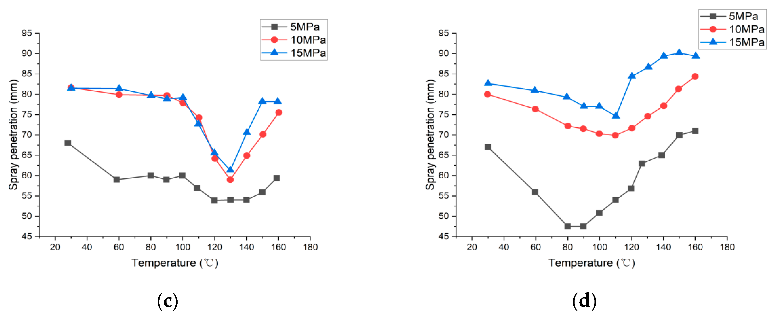
4.4. Effect of Injection Pressure on Penetration Distance

Figure 12 proves that spray penetration generally grows with an increase in the injection pressure, due to the higher initial velocity and initial kinetic energy. As can be inferred, the spray penetration does not increase linearly with the injection pressure. When the injection temperature increases and reaches the flash-boiling condition, the mixture evaporation causes a drop in the fuel penetration because most of the macroscopic kinetic energy is diverted to the radial spray development; the valleys of the penetration length in Figure 12a–d correspond to the peaks of the spray angle in Figure 11. The already-mentioned additional momentum, caused by flash boiling and the subsequent collapse of the distinct gasoline–water plumes, promotes the axial spray propagation. This effect is more remarkable at higher injection pressures because the aerodynamic drag force increment acting on the spray under flash-boiling conditions becomes less important. Conversely, if a low-pressure injection spray is considered, the pronounced reduction in the mixture droplet dimensions, due to flash-boiling, leads to a stronger effect of the aerodynamic drag force, which counterbalances the axial spray propagation tendency [37].

4.5. Effect of Injection Pressure on Spray Angle

Figure 13 reports the spray cone angle as a function of the injection temperature at three distinct Pj values for the G0, G50, G70 and G100 fuels. For G0, G50 and G70, the spray angle first increases and then decreases with the rising injection temperature. Instead, the spray angle reduces almost continuously with the injection temperature for G100, except in the Pj = 5 MPa case (cf. also Figure 11). In Figure 13a–c, the spray cone angle increases with Pj before the local maximum point with respect to the injection temperature was reached; on the other hand, once such a maximum point has been surpassed, the spray angle at 5 MPa is the largest and the spray angles referring to 10 MPa and 15 MPa take similar values. In fact, below the flash-boiling temperature, an increase in Pj leads to a reduction in the fluid particle diameter and to an enhanced spray diffusion. Therefore, the higher is the injection pressure, the more expanded the spray on both sides and the larger the spray angle. When the temperature is close to the flash-boiling one, the spray angle sharply increases for all the examined injection pressure values. In fact, as the fuel temperature rises, the surface tension diminishes, the nucleation rate accelerates and micro explosions of bubbles at the nozzle outlet make the spray wider [36]. As soon as the temperature goes beyond the flash boiling point, the collapse of the spray plumes promotes axial propagation, leading to a reduction in the spray angle, for all the Pj values. However, as already mentioned in Section 4.4, the spray featuring Pj = 5 MPa experiences a higher aerodynamic drag force beyond the flash-boiling condition that counteracts the axial propagation, keeping the spray width larger if compared with the sprays with higher Pj values.

5. Conclusions

A real time gasoline–water mixing system was designed. The fuel mixture preparation and its spray characteristics were studied. The main conclusions are listed in what follows.
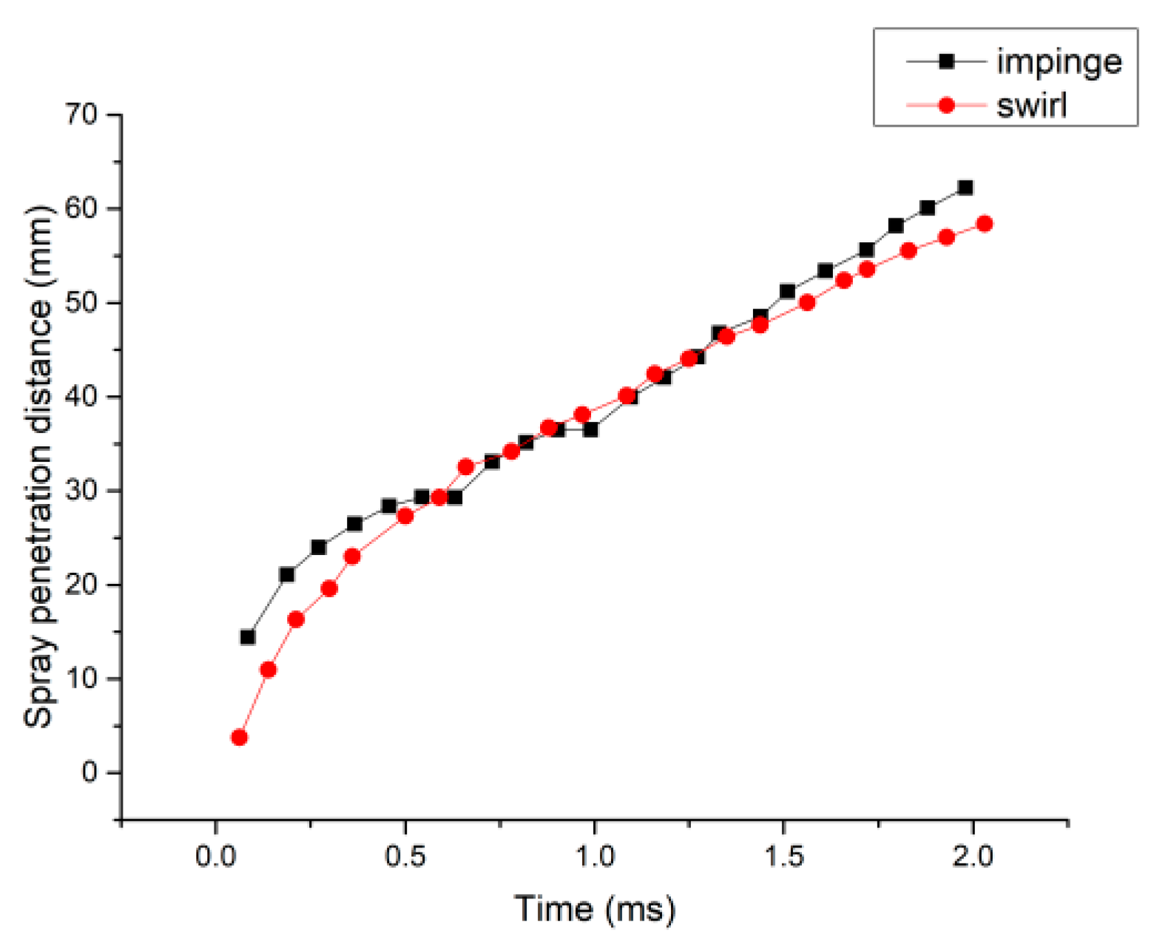
  • The RGB analysis (mean values and standard deviations) is used as a quantitative tool for evaluation of the mixing characteristics of the obtained real-time gasoline–water mixture and of the performance of the new gasoline–water mixing technique based on impingement. The RGB values and their standard deviations were determined by selecting a particular image-processing area. When the injection pressure increases, the uniformity and time stability of the gasoline–water fuel mixture improves: the longest obtained stability is 5 h and a saturation for the impingement pressure (Pimp) occurs at 20 MPa.
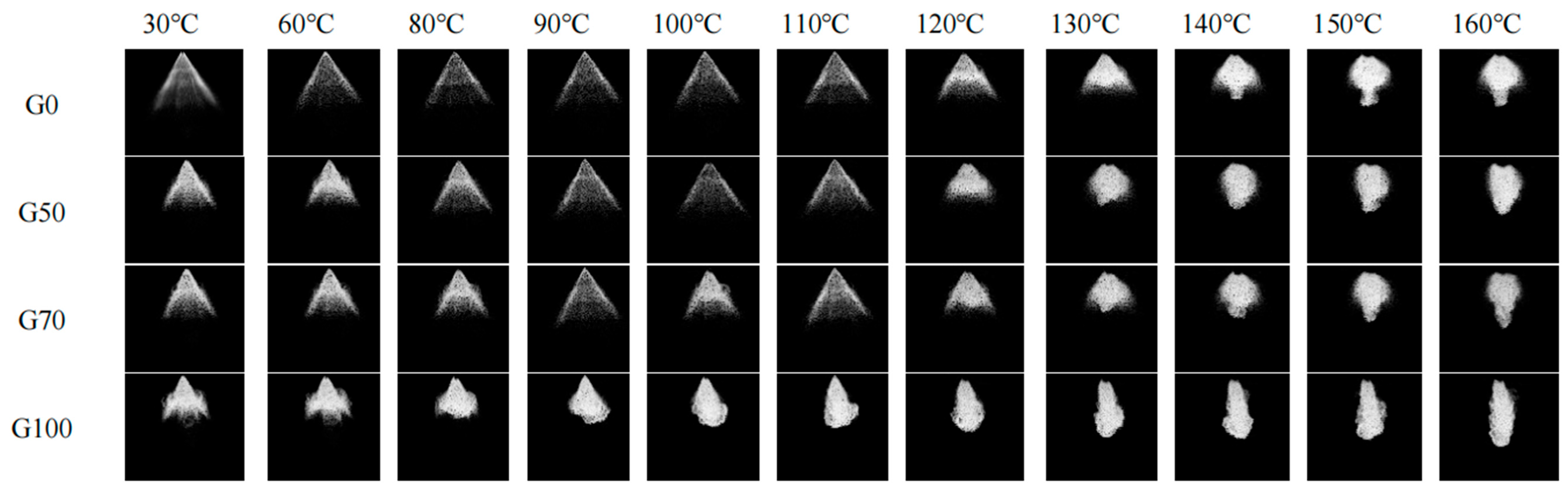
  • As the temperature increases, the spray penetration referring to G0, G50, G70 and G100 decreases and then increases: the local minimum point virtually coincides with the flash boiling condition. A significant reduction in penetration length is due to the momentum loss caused by the evaporation and the diminished inertial force. After the flash-boiling condition, the spray plumes collapse in a single spray characterized by an augmented axial momentum, that allow the penetration to rise again.
  • The spray cone angles of G0, G50 and G70 increase slowly and similarly as the injection temperature rises. The spray angle of the gasoline–water mixture is mainly determined by the water. For the G100, when the injection temperature reaches the flash boiling value (around 75 °C) of gasoline, the spray cone angle drops sharply. Instead, for a gasoline–water mixture, when the flash-boiling point of water is reached (around 130 °C), a large amount of steam is generated, which increases the spray angle. However, when the temperature overwhelms the flash-boiling condition, in the 140–160 °C range, the spray plume collapse leads to a dramatic drop in the spray angle.
  • By increasing the injection pressure (Pj), the penetration length of the spray generally augments for a fixed injection temperature. Before the flash-boiling condition, the angle increases with the injection pressure, due to a promoted nucleation and the occurrence of micro explosions of bubbles near the nozzle, which make the spray wider. Beyond the flash-boiling temperature, the spray plume collapse reduces the spray angle and enhances the axial penetration. This effect is less evident for the lowest injection pressure, since in this case the spray experiences a higher aerodynamic drag force beyond the flash-boiling condition that counteracts the axial propagation, keeping the spray width larger if compared with the sprays with higher Pj values.

Author Contributions

Conceptualization, Z.W. and L.F.; methodology, A.F., M.J., O.V., L.F. and Z.W.; software, M.J.; validation, M.J.; formal analysis, A.F., M.J., O.V. and Z.W.; data curation, M.J.; writing—original draft preparation, A.F., M.J. and O.V.; writing—review and editing, A.F., M.J., Z.W. and O.V.; supervision, A.F., Z.W. and L.F.; funding acquisition, Z.W. All authors have read and agreed to the published version of the manuscript.

Funding

This work was funded by the National Natural Science Foundation of China (Grant No. U1832179).

Data Availability Statement

Not applicable.

Conflicts of Interest

The authors declare no conflict of interest.

References

  1. BP World Energy Outlook 2020-Possible Developments in Global Energy to 2050. Available online: https://www.bp.com/en/global/corporate/news-and-insights/press-releases/bp-energy-outlook-2020.html (accessed on 14 September 2020).
  2. BP Statistical Review of World Energy 2021 70th Edition. Available online: https://www.bp.com/content/dam/bp/business-sites/en/global/corporate/pdfs/energy-economics/statistical-review/bp-stats-review-2021-full-report.pdf (accessed on 1 July 2021).
  3. Ferrari, A.; Vento, O. Influence of frequency-dependent friction modeling on the simulation of transient flows in high-pressure flow pipelines. J. Fluids Eng. 2020, 142, 081205. [Google Scholar] [CrossRef]
  4. Ferrari, A.; Vento, O. Thermal effects on Common Rail injection system hydraulic performance. Int. J. Engine Res. 2023, 14680874231162412. [Google Scholar] [CrossRef]
  5. Ferrari, A.; Novara, C.; Paolucci, E.; Vento, O.; Violante, M.; Zhang, T. Design and rapid prototyping of a closed-loop control strategy of the injected mass for the reduction of CO2, combustion noise and pollutant emissions in diesel engines. Appl. Energy 2018, 232, 358–367. [Google Scholar] [CrossRef]
  6. Ferrari, A.; Novara, C.; Paolucci, E.; Vento, O.; Violante, M.; Zhang, T. A new closed-loop control of the injected mass for a full exploitation of digital and continuous injection-rate shaping. Energy Convers. Manag. 2018, 177, 629–639. [Google Scholar] [CrossRef]
  7. Ferrari, A.; Novara, C.; Vento, O.; Violante, M.; Zhang, T. A novel fuel injected mass feedback-control for single and multiple injections in direct injection systems for CI engines. Fuel 2023, 334, 126670. [Google Scholar] [CrossRef]
  8. Ferrari, A.; Jin, Z.; Vento, O.; Zhang, T. An injected quantity estimation technique based on time–frequency analysis. Control. Eng. Pract. 2021, 116, 104910. [Google Scholar] [CrossRef]
  9. Jin, Z.; Vento, O.; Zhang, T.; Ferrari, A.; Mittica, A.; Ouyang, L.; Tan, S. Numerical-Experimental Optimization of the Common-Feeding Injection System Concept for Application to Light-Duty Commercial Vehicles. ASME J. Energy Resour. Technol. 2021, 143, 122304. [Google Scholar] [CrossRef]
  10. Shahed, S.M.; Bauer, K.H. Parametric studies of the impact of turbocharging on gasoline engine downsizing. SAE Int. J. Engines 2009, 2, 1347–1358. [Google Scholar] [CrossRef]
  11. Reitz, R.D. Directions in internal combustion engine research. Combust. Flame 2013, 160, 1–8. [Google Scholar] [CrossRef]
  12. Bozza, F.; Siano, D.; Torella, E. Cycle-by-cycle analysis, knock modeling and spark-advance setting of a “downsized” spark-ignition turbocharged engine. SAE Int. J. Engines 2010, 2, 381–389. [Google Scholar] [CrossRef]
  13. Fontana, G.; Galloni, E. Knock Resistance in a Small Turbocharged Spark-Ignition Engine; SAE Technical Paper; SAE International: Warrendale, PA, USA, 2006. [Google Scholar] [CrossRef]
  14. Dahnz, C.; Spicher, U. Irregular combustion in supercharged spark ignition engines–pre-ignition and other phenomena. Int. J. Engine Res. 2010, 11, 485–498. [Google Scholar] [CrossRef]
  15. Attard, W.P.; Toulson, E.; Watson, H.; Hamori, F. Abnormal Combustion Including Mega Knock in a 60% Downsized Highly Turbocharged PFI Engine; SAE Technical Paper; SAE International: Warrendale, PA, USA, 2010. [Google Scholar] [CrossRef]
  16. Wang, Z.; Liu, H.; Song, T.; Qi, Y.; He, X.; Shuai, S.; Wang, J. Relationship between super-knock and pre-ignition. Int. J. Engine Res. 2015, 16, 166–180. [Google Scholar] [CrossRef]
  17. Qi, Y.; Wang, Z.; Wang, J.; He, X. Effects of thermodynamic conditions on the end gas combustion mode associated with engine knock. Combust. Flame 2015, 162, 4119–4128. [Google Scholar] [CrossRef]
  18. Lanzafame, R. Water Injection Effects in a Single-Cylinder CFR Engine; SAE Technical Paper; SAE International: Warrendale, PA, USA, 1999. [Google Scholar] [CrossRef]
  19. Miganakallu, N.; Naber, J.D.; Rao, S.; Atkinson, W.; Barros, S. Experimental investigation of water injection technique in gasoline direct injection engine. In Proceedings of the Internal Combustion Engine Division Fall Technical Conference, Washington, DC, USA, 15–18 October 2017. [Google Scholar] [CrossRef]
  20. Worm, J.; Naber, J.; Duncan, J.; Barros, S.; Atkinson, W. Water injection as an enabler for increased efficiency at high-load in a direct injected, boosted, SI engine. SAE Int. J. Engines 2017, 10, 951–958. [Google Scholar] [CrossRef]
  21. Mingrui, W.; Sa, N.T.; Turkson, R.F.; Jinping, L.; Guanlun, G. Water injection for higher engine performance and lower emissions. J. Energy Inst. 2017, 90, 285–299. [Google Scholar] [CrossRef]
  22. Hunger, M.; Böcking, T.; Walther, U.; Günther, M.; Freisinger, N.; Karl, G. Potential of direct water injection to reduce knocking and increase the efficiency of gasoline engines. In Proceedings of the Knocking in Gasoline Engines: 5th International Conference, Berlin, Germany, 12–13 December 2017. [Google Scholar] [CrossRef]
  23. De Bellis, V.; Bozza, F.; Teodosio, L.; Valentino, G. Experimental and numerical study of the water injection to improve the fuel economy of a small size turbocharged SI engine. SAE Int. J. Engines 2017, 10, 550–561. [Google Scholar] [CrossRef]
  24. Kadota, T.; Yamasaki, H. Recent advances in the combustion of water fuel emulsion. Prog. Energy Combust. Sci. 2002, 28, 385–404. [Google Scholar] [CrossRef]
  25. Zhu, S.; Hu, B.; Akehurst, S.; Copeland, C.; Lewis, A.; Yuan, H.; Branney, C. A review of water injection applied on the internal combustion engine. Energy Convers. Manag. 2019, 184, 139–158. [Google Scholar] [CrossRef]
  26. Wu, Z.; Xie, W.; Yu, Y.; Li, L.; Deng, J. Comparison of spray characteristics of gasoline and water-in-gasoline mixture at elevated fuel temperature conditions. Fuel 2021, 304, 121409. [Google Scholar] [CrossRef]
  27. Zhou, X.; Zhai, Q.; Hung, D.L.; Li, X.; Xu, M. Study of component proportion effects on flash boiling atomization with ternary-alkane fuel mixtures. Fuel 2021, 298, 120798. [Google Scholar] [CrossRef]
  28. Yan, J.; Gao, S.; Liu, W.; Chen, T.; Lee, T.H.; Lee, C.F. Experimental study of flash boiling spray with isooctane, hexane, ethanol and their binary mixtures. Fuel 2021, 292, 120415. [Google Scholar] [CrossRef]
  29. Senda, J.; Asai, T.; Kawaguchi, B.; Fujimoto, H. Characteristics of gas-dessolved diesel fuel spray: Spray characteristics and simulating flash boiling process. JSME Int. J. Ser. B Fluids Therm. Eng. 2000, 43, 503–510. [Google Scholar] [CrossRef]
  30. Senda, J.; Wada, Y.; Kawano, D.; Fujimoto, H. Improvement of combustion and emissions in diesel engines by means of enhanced mixture formation based on flash boiling of mixed fuel. Int. J. Engine Res. 2008, 9, 15–27. [Google Scholar] [CrossRef]
  31. Vellaiyan, S.; Amirthagadeswaran, K.S. The role of water-in-diesel emulsion and its additives on diesel engine performance and emission levels: A retrospective review. Alex. Eng. J. 2016, 55, 2463–2472. [Google Scholar] [CrossRef]
  32. Ithnin, A.M.; Noge, H.; Kadir, H.A.; Jazair, W. An overview of utilizing water-in-diesel emulsion fuel in diesel engine and its potential research study. J. Energy Inst. 2014, 87, 273–288. [Google Scholar] [CrossRef]
  33. Heinrich, C.; Dörksen, H.; Esch, A.; Krämer, K. Gasoline water direct injection (GWDI) as a key feature for future gasoline engines. In Proceedings of the Knocking in Gasoline Engines: 5th International Conference, Berlin, Germany, 12–13 December 2017. [Google Scholar] [CrossRef]
  34. Tamir, A.; Kitron, A. Applications of impinging-streams in chemical engineering processes. Chem. Eng. Commun. 1987, 50, 241–330. [Google Scholar] [CrossRef]
  35. Wang, Z.; Wu, S.; Huang, Y.; Huang, S.; Shi, S.; Cheng, X.; Huang, R. Experimental investigation on spray, evaporation and combustion characteristics of ethanol-diesel, water-emulsified diesel and neat diesel fuels. Fuel 2018, 231, 138–448. [Google Scholar] [CrossRef]
  36. Liu, Y.; Yu, Y.; Hou, X.; Wu, Z. Effects of Water Addition on Flash-Boiling Spray of Gasoline and Gasoline/Water Mixtures; SAE Technical Paper; SAE International: Warrendale, PA, USA, 2023. [Google Scholar] [CrossRef]
  37. Kapusta, Ł.J. Understanding the collapse of flash-boiling sprays formed by multi-hole injectors operating at low injection pressures. Energy 2022, 247, 123388. [Google Scholar] [CrossRef]
  38. Zeng, W.; Xu, M.; Zhang, G.; Zhang, Y.; Cleary, D.J. Atomization and vaporization for flash-boiling multi-hole sprays with alcohol fuels. Fuel 2012, 95, 287–297. [Google Scholar] [CrossRef]
  39. Yu, Y.S.; Shin, D.; Jeong, M.; Park, J.; Park, S. Effect on flash boiling spray characteristics in the far-field and near-field and nozzle tip wetting with multi-hole LPDI injector. Appl. Therm. Eng. 2023, 219, 119676. [Google Scholar] [CrossRef]
Figure 1. The principle of the high-pressure impinging flow.
Energies 16 06026 g001
Figure 2. (a) The test bench for preparation of the real-time gasoline–water mixture: 1—N2 tank, 2—pressure-reducing valve, 3—pressure sensor, 4—Gas–liquid booster pump, 5—solenoid valve, 6—thermocouple, 7—temperature relay, 8—Gasoline–water real-time mixture equipment, 9—collision system, 10—relay, 11—water, 12—gasoline, 13—gasoline–water mixture, 14—switch. (b) The layout of the gasoline–water impingement mixing device.
Energies 16 06026 g002
Figure 3. (a) Gasoline–water impingement mixture (ratio 1:1, Pimp = 25 MPa) and the image-processing area; (b) microgram of gasoline–water mixture fuel using the swirl method [26]; and (c) the stratification of the G70 mixture (5 h of settling, Pimp = 25 MPa).
Energies 16 06026 g003
Figure 4. The impact of the impingement pressure on standard deviation for gasoline–water mixtures: (a) R, G, and B standard deviation for a 1:1 mixing ratio at different injection pressures; and (b) RGB standard deviation with respect to the injection pressure, for different mixing ratios.
Energies 16 06026 g004
Figure 5. The gasoline–water mixture spray test bench.
Energies 16 06026 g005
Figure 6. Spray image processing: (a) original figure; (b) background removed; (c) binarization treatment; (d) contour extraction.
Energies 16 06026 g006
Figure 7. Spray characterization of G70 at injection temperature of 60 °C and injection pressure of 5 MPa.
Energies 16 06026 g007
Figure 8. Snapshots for various gasoline–water mixture sprays at Pj = 5 MPa and at different injection temperatures.
Energies 16 06026 g008
Figure 9. The comparison of penetration lengths referring to different mixing methods (140 °C, Pj = 5 MPa, G70).
Energies 16 06026 g009
Figure 10. Effect of different injection temperatures on the penetration distance (Pj = 5 MPa).
Energies 16 06026 g010
Figure 11. Effect of different injection temperatures on the spray angle (Pj = 5 MPa).
Energies 16 06026 g011
Figure 12. Effect of different injection pressures on the penetration length: (a) G0; (b) G50; (c) G70; (d) G100.
Energies 16 06026 g012aEnergies 16 06026 g012b
Figure 13. Effect of different injection pressures on the spray angle: (a) G0; (b) G50; (c) G70; (d) G100.
Energies 16 06026 g013aEnergies 16 06026 g013b
Table 1. The RGB relative standard deviation values pertaining to different mixing methods.
G50 (Swirl)G70 (Swirl)G70 (Impingement)
RGB standard deviation2.28%2.05%1.65%
R standard deviation2.96%2.13%1.69%
G standard deviation2.37%2.04%1.75%
B standard deviation1.51%1.69%1.53%
Table 2. R, G, and B and relative standard deviation values of settled and unsettled impinging gasoline–water mixture (ratio 9:4, Pimp = 25 MPa).
Unsettled MixtureSettled Mixture (5 h)
R mean value235.7134.6
G mean value240.2143.2
B mean value242.3142.9
R standard deviation1.70%6.46%
G standard deviation1.75%5.73%
B standard deviation1.53%5.67%
RGB standard deviation1.66%5.95%
Table 3. The stability time of different gasoline–water mixtures.
Pressure [MPa]The Stability Time (Ratio 1:1) [h]The Stability Time (Ratio 9:4) [h]
522
1033
1533
2055
2555
Table 4. Test conditions.
Parameter
Injection pressure Pj [MPa]5, 10, 15
Gasoline–water volumetric ratioG0, G50, G70, G100
Injection temperature [°C]30–160
Disclaimer/Publisher’s Note: The statements, opinions and data contained in all publications are solely those of the individual author(s) and contributor(s) and not of MDPI and/or the editor(s). MDPI and/or the editor(s) disclaim responsibility for any injury to people or property resulting from any ideas, methods, instructions or products referred to in the content.

