This section introduces a review of the Technology Readiness Levels of current superconducting machine projects. First, a discussion about TRLs and their application to superconducting machines is laid forward. Then, the full review is presented with a focus on projects with TRL ≥ 3, starting from 2017.
3.1. Technology Readiness Levels
Technology Readiness Levels are a useful tool to assess the maturity of a technology. NASA proposed it in the 1980s to evaluate the states of technologies to be used in the Aerospace industry. Nowadays, it is part of NASA’s Systems Engineering Technology Assessment process. Systems engineering is a multi-disciplinary methodology to develop, manage, operate, and retire a system [
53]. A system can be defined in many ways, but overall, it can be thought of as a set of devices, personnel, and software that, working together, meets a certain need [
53]. Technology evaluation or assessment is crucial to the systems engineering approach because it provides all the information necessary for system design and operation.
TRL assessment involves the entire technological development process. The evaluation starts with basic research and goes on to prototype development, system development, and launch operation [
53]. There are nine Technology Readiness Levels, as presented in
Table 4. The first three levels are focused on basic research. TRL 1 is achieved when the basic principles have been observed and published. TRL 2 comprises the definition of the technology and the applications proposed for it. Furthermore, the third TRL, TRL 3, focuses on the proof of concept conducted via analysis and experiments. In TRL 3, the critical function of the device is demonstrated.
From TRL 4 to TRL 6, technology development is focused on product validation. Validation, in this context, is linked to stakeholders’ expectations. A product has been validated if it meets the stakeholders’ expectations to operate appropriately in the intended environment. The stakeholders (all people, companies, laboratories, governments, etc., involved in the project) and their expectations of the technology must be clearly stated. TRL 4 is achieved when a technology has been validated in a laboratory environment. TRL 5 focuses on validation in a relevant environment, emulating operating conditions. TRL 6 is achieved when a prototype is fully demonstrated in a relevant environment, close to the one expected during actual operation without all the systems.
TRLs 7 and 8 are part of the system development. TRL 7 is achieved when the system prototype is demonstrated in the target environment. Demonstration, in this case, means a full demonstration and assessment of the technology in all possible modes of operation. TRL 8 is achieved when the system is completed and fully validated. TRL 9 is achieved when the technology is in full use.
The
NASA Engineering Systems Handbook [
53] recommends that to assess the TRL of a given system/subsystem correctly, it is necessary to ensure that all the terminology used in TRL assessment is clearly defined for this particular subsystem; for instance, the definitions of the basic principles, what validation means, and what type of measurements, simulations, and modeling should be carried out to establish a certain TRL level.
This paper aims to address this problem by suggesting a step-by-step approach, alongside the terminology, that could be applied to the assessment of Superconducting Electric Machinery. This ensures that, even with a few judgment calls that may happen to all TRL assessments, the SEMs are evaluated with the most straightforward, clearly stated criteria. This approach is likely to generate a more objective than subjective evaluation of SEMs, contributing to their future developments and applications.
3.2. Application of TRLs to Superconducting Electric Machinery
TRL 1 focuses on the definitions and investigations of the basic principles of the technology. For electric machinery, the basic principles are related to the correct energy conversion from electric energy to mechanical energy or vice versa. This means that the device must develop force or torque if electric energy is provided to it or generates electric energy given some external force or torque. This, of course, applies to SEMs. Here, it is proposed that the basic principles expected from a superconducting machine are validated by using numerical and/or analytical results and/or experiments demonstrating the energy conversion as intended. Simulations, analytical, or experimental proofs of basic torque/force–speed relations and/or torque/force–input current/voltage relations are necessary to prove the operation as a motor. To prove the operation as a generator, current/voltage–force/torque curves from simulations and/or experiments are needed. As the superconductor is highly dependent on the temperature, some information about the operating conditions, such as fixed temperature, adiabatic system, etc., should be stated to be considered in the model. Analysis of expected regions of operation regarding temperature, magnetic field, and current density should be addressed, as they define the state of the material (superconductor or normal resistivity). This allows the move up the TRL ladder.
TRL 2 is the definition of the technological concept and the application. In this TRL, more technical details should be included and/or discussed, as it is at this stage that the end application is defined. So, in this TRL, it is important to clearly state the purpose (for instance, aircraft propulsion, aircraft control, vessel propulsion, wind power, etc.) and to address how the SEM will be built for it. Hence, a more specific design is needed, such as the designated number of magnetic poles and expected speed (synchronous, asynchronous, both, speed ranges, etc.), expected force/torque, and current/voltage requirements. Furthermore, some information on the cryogenic system is welcome, such as the definition of expected temperature range and the type of cryogenic system that may best suit this application.
In this work, the discussion concerns Superconducting Electric Machinery projects that have achieved TRLs equal to or greater than 3. This means that they should have been tested via simulations and experiments in a laboratory environment. This excludes topology and design proposals and optimizations conducted solely with simulations. To achieve TRL 3, a project needs to have demonstrated the SEM’s critical functions. This includes experimental proof that the machine has the electromechanical characteristics defined in TRL 2. Consequently, force/torque versus speed and force/torque versus current/voltage measurements are expected, along with temperature information. For example, for a synchronous machine to be operated at 77 K, experimental proof should demonstrate that the machine can achieve and hold synchronous speed at its operating temperature.
According to [
53], TRLs 4 and 5 depend on “component and/or breadboard” validation. In the present case, a “breadboard” prototype is a subscale prototype that has been tested in a laboratory environment. A full-scale prototype needs to be tested in a proper environment that simulates the expected conditions of the basic operation of the machine. This definition is important to distinguish TRLs 4 and 5. Here, it is proposed that the validation steps for TRLs equal to or greater than 4 should include a full assessment of the machine. This includes not only the measurements required for TRL 3 but also thermal measurements or, at least, some description of the thermal conditions and electromechanical measurements (torque, speed, voltage, and current) with and without load, giving a full analysis of all possible operation points of the machine. All these aspects should be validated, i.e., compared to the stakeholders’ expectations: to the intended design, to application requirements, etc.
Furthermore, for TRLs 5 and 6, a “relevant environment” is needed. As mentioned previously, a relevant environment is the one that mimics or emulates the actual environment, also called target environment by the
Systems Engineering Handbook [
53]. As it depends on the proposed application, it might vary between projects. For example, for a machine whose purpose is to be used in aircraft propulsion, one may look for experiments conducted in flight demonstrators, where the machine is submitted to conditions similar to those encountered during flights. For machines applied to wind turbines, one should look for experiments conducted with the presence of the turbines and so forth. The experiments should consist of the same type as the ones conducted in TRL 4, or more thorough. For TRL 6, one expects the full system to be validated, including the machine itself, the control systems, the cryogenic system, and any other system identified as needed for machine operation during the previous stages of development.
TRL 7 also depends directly on the application, so one looks for machines fully tested on-site. TRLs 8 and 9 mean a fully completed system, and for TRL 9, proof of continued use is required. A fully completed system for an electric machine means that the machine can be fully controlled and is fully stable and its operation is reliable. Another important aspect to consider is the possibility of change in the proposed application/use environment. According to NASA [
53], if a technology is rated at TRLs greater than 5, but its environment has changed, the TRL goes back to TRL 5. This rule is also applied in the present case.
Table 5 summarizes the TRL assessment for SEMs.
3.3. Review of the TRLs of SEM Projects
Reference [
10] has made a thoughtful analysis of SEM projects, including TRL assessment, for projects up to 2017. So, the analysis presented in this work extends from 2017 to the present day.
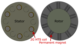
In our overall evaluation, one project demonstrated enough details to be classified as TRL 7: a synchronous generator for wind power applications developed by the EU 2020 EcoSwing project. According to the project website [
47], it is the “world’s first demonstration of a superconducting low-cost, lightweight drivetrain on a modern 3.6 MW wind turbine”. The project included nine institutions from academia and industry. They developed a full-scale generator installed in a wind turbine [
40,
41]. The HTS machine is composed of superconducting field windings placed in the rotor and a conventional armature winding in the stator. A rotor back iron is used as a flux concentrator. The machine was first tested on the ground, where HTS winding excitation, short-circuit, stator-heat run, no-load, and partial power production tests were performed. A quench happened in one of the HTS coils, which was replaced with ease. Then, the prototype was installed in the wind turbine and tested. The full test was conducted in five steps: rotor cool-down, first excitation of the field winding, first power production, second excitation of the field winding, and second power production. Excitation and power production were divided into two steps to reduce risks. During the power production stages, three short-circuit events happened. According to [
41], the HTS technology had excellent performance, even during the short-circuit events. With more than 650 h connected to the grid, the HTS generator provided more than 600 MWh to the Danish electric grid, including the first time in history that an HTS generator delivered electric power to a grid [
41]. The project successfully places the HTS generator for wind power applications in a TRL range between 6 and 7, according to [
41], which is in agreement with our evaluation. It is a very important project to the field, as it provided a fully tested prototype, developed by academia and industry.
Another advanced project was the one developed by Yanamoto et al. [
42], which has been attributed a TRL 5. This project has been led by The Tokyo University of Marine Science and Technology as well as the Kawasaki Heavy Industries, with the Ministry of Economy, Trade and Industry from Japan since 2007. In [
42], the authors described the load test program applied to a 3 MW HTS motor. These tests were conducted in the HTS motor test facility, which has the capability to reproduce real-life load scenarios of sea vessel propulsion. The partially superconducting machine is a radial-flux synchronous motor with a DI-BSCCO winding and an air-core rotor shaft. They ran constant load (performance and 100 h endurance) and variable load tests. According to [
42], the motor demonstrated reliable operation during the tests. In the present case, the machine has been thoroughly tested in an environment built specifically to mimic real-life operation, being eligible to be considered a “relevant” environment in the TRL classification procedure.
Table 6 summarizes all the papers and projects that were reviewed and their TRL. All projects were considered to have achieved TRL 1, as the basic principles of all types of SEMs presented here had already been tested. TRL 2 is very application-specific, and it is common to find projects that would fulfill TRL 2 based on a basic, non-application-specific design defined by the stakeholders. They were also attributed TRL 2 for this evaluation, but it is recommended that future projects include more application-specific design in their research, as we argue later in the text. Most of the evaluated projects amounted to TRLs 3 and 4, meaning that the overall SEM technology has been experimentally proven as proof of concept, and most topologies were investigated with a prototype tested in a laboratory environment.
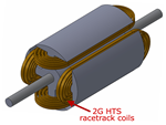
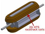
Most prototypes were classified as synchronous machines, working as either generators, motors, or both. In this case, as explained in
Section 2.3, the field winding is superconducting and directly fed with DC current. Both partially and fully superconducting machines have been investigated. For all machines, but especially for fully superconducting machines, the targeted scenario is to dramatically reduce or eliminate the use of ferromagnetic materials, meaning that the machine operates with air cores in the rotor and/or the stator. One of the main concerns for this type of machine is related to the AC losses and, therefore, heat generation.
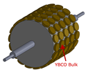
This research has found that the number of projects of trapped-flux radial machines, induction machines, and linear machines is lower than the number of projects dealing with synchronous machines. For trapped-flux machines, there is no current directly supplied to the field winding, rather it is induced. Most prototypes are partially superconducting machines with some type of ferromagnetic core. This is important because, as defined in
Section 2.3, those cores help the magnetization process. The main concern in this case is to correctly assess all modes of operation of these machines. In operation, the machines can switch between synchronous and asynchronous modes, or they can be used in one of the two modes. This has been conducted for the investigated prototypes [
29,
31,
32,
33], with special attention to the synchronous mode of operation, as this is the one with the lowest AC losses.
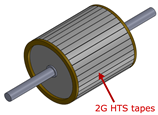
The linear machine project reviewed here is a transverse flux linear motor [
68]. It uses a hybrid secondary coil with Aluminum and short-circuited superconducting HTS tapes, relying on induced current in the stacks of HTS tapes.
With regard to magnetic flux, both radial-flux and axial-flux rotating machines have reached up to TRL 4. Projects with axial-flux machines tend to be less common. However, many different axial-flux machine configurations are investigated, for example, prototypes with ferromagnetic cores in [
35] and without ferromagnetic cores [
48] have been proposed, or under different operations, such as motor [
61] and generator [
35], as well. Material and shape diversities are also observed in the prototypes: 1G HTS coils [
35], bulks, and NbTi coils [
62], for instance.
As for applications, wind power applications are more advanced and constitute the majority of the projects, with the largest TRL, such as the EcoSwing project at TRL 7. Aircraft propulsion applications come second in the number of projects, followed by wave energy, transportation applications (MagLev, etc), marine propulsion, and, finally, power system stability.
Additionally, it is interesting to sort out the SEM patents that have been submitted within the same period of time (2017–2022). Our research has found 12 different patents that were submitted and/or published as patents in the US, China, Japan, South Korea, Europe, Germany, and the international patent offices. Four companies appear as patent holders: General Electric (GE), American Superconductor (AMSC), Siemens, and Rolls-Royce, as listed in
Table 7. Some of these projects clearly state the machine application, mostly wind power. Furthermore, one can observe the particular focus on partially superconducting machines with the superconductors used in the field winding. All projects were submitted as patents to more than one patent office. Here, only one patent ID is used.


 ,
, 

