Article

Effect of Microporous Layer Ink Homogenisation on the Through-Plane Gas Permeability of PEFC Porous Media

by
Narvin D. Neehall
1,
Mohammed S. Ismail
2,
Kevin J. Hughes
3,* and
Mohamed Pourkashanian
3,4
1
ICSI Energy, National Research and Development Institute for Cryogenic and Isotopic Technologies, 240050 Ramnicu Valcea, Romania
2
School of Engineering, University of Hull, Hull HU6 7RX, UK
3
Energy Institute, The University of Sheffield, Sheffield S3 7RD, UK
4
Translational Energy Research Centre, The University of Sheffield, Sheffield S3 7RD, UK
*
Author to whom correspondence should be addressed.
Energies 2023, 16(16), 5944; https://doi.org/10.3390/en16165944
Submission received: 4 July 2023 / Revised: 26 July 2023 / Accepted: 4 August 2023 / Published: 11 August 2023
(This article belongs to the Special Issue Current Advances in Fuel Cell Technology)

Abstract

:
The through-plane gas permeability and morphology of PEFC gas diffusion media (GDM) is investigated for different microporous layer (MPL) ink homogenisation techniques (bath sonication and magnetic stirring) for low- (Vulcan XC-72R) and high (Ketjenblack EC-300J)-surface-area carbon powders. The MPL composition is held constant at 80 wt.% carbon powder and 20 wt.% PTFE for a carbon loading of 1.0 mg cm−2. The MPL ink homogenisation time is held constant at two hours for both techniques and increased by one hour for bath sonication to compare with previous investigations. The results show that the through-plane gas permeability of the GDM is approximately doubled using magnetic stirring when compared with bath sonication for MPLs composed of Vulcan XC-72R, with a negligible change in surface morphology between the structures produced from either homogenisation technique. The variation in through-plane gas permeability is almost negligible for MPLs composed of Ketjenblack EC-300J compared with Vulcan XC-72R; however, MPL surface morphology changes considerably with bath sonication, producing smoother, less cracked surfaces compared to the large cracks produced via magnetic stirring for a large-surface-area carbon powder. An MPL ink sonication time of three hours results in a percentage reduction in through-plane gas permeability from the GDL substrate permeability by ~72% for Ketjenblack EC-300J compared to ~47% for two hours.

1. Introduction

Polymer electrolyte fuel cells (PEFCs) have gained increasing attention as power sources in automotive, portable, and stationary applications, due to rapid start-ups at low temperatures, quiet operation, high efficiencies, and possible zero emissions [1,2,3,4,5,6,7,8,9,10]. PEFCs are limited by the cost, performance, and durability of the device; as such, optimisation of the cell components is needed to facilitate wider commercialisation [8,10,11,12]. The gas diffusion media (GDM) is a crucial component in the membrane electrode assembly (MEA) of the PEFC, as it facilitates the transport of reactant gases to the catalyst layer (CL) and has a substantial impact on the efficiency of the cell, as it regulates the heat and water produced because of the electrochemical reaction [6,9].
The GDM typically consists of a macroporous carbon substrate (referred to as a gas diffusion layer or GDL) coated with a thin, microporous layer (MPL), which consists of a mixture of carbon powder and polytetrafluorethylene (PTFE) [6,10,13]. Both the GDL and MPL are typically hydrophobised with the use of 5–30 wt.% and 10–40 wt.% PTFE, respectively [14]. GDLs are usually non-woven straight carbon fibre paper, carbon felt-fibre paper, or woven carbon cloth [10]. The MPL composition is characterised by the type and loading of the carbon powder and hydrophobic agent used [6].
The permeability of the GDM is an intrinsic property, which is affected by the pore size, anisotropy, and tortuosity of the GDL and the MPL [5,13]. Generally, higher gas permeability would result in improved catalytic activity [5,15]. Accurate values of gas permeability are essential in describing water saturation profiles of the GDM in PEFC models [3,4]. Gas permeability is either measured in the through-plane (traverse) or in-plane (lateral) direction due to the anisotropic nature of the GDL [5,6]. There have been several experimental investigations into the gas permeability of the GDL and GDM [1,2,3,4,5,6,16,17,18,19,20,21,22,23,24,25,26,27]; however, the majority of these focused on commercial GDLs and GDM with the exception of refs. [3,4,6], where the GDM were prepared by considering the carbon powder type, carbon loading, and PTFE loading on the through-plane gas permeability. Furthermore, there have been far less investigations apart from [25], which focused on the MPL ink homogenisation method on gas permeability and surface morphology of the GDM.
Orogbemi et al. [3,4] concluded that there was a decrease in through-plane gas permeability with an increase in carbon loading for GDM prepared on carbon felt-fibre paper containing 5% PTFE- SGL 10BA. This is, however, not always the case, as shown by Neehall et al. [6]. Neehall et al. [6] showed that the type of carbon powder (high or low surface area) used in preparation of the MPL in combination with the base structure (non-woven straight or carbon felt fibre paper) of the GDL resulted in an increase in through-plane gas permeability with increased carbon loading for MPLs composed of high-surface-area carbon powder coated onto non-woven straight fibre carbon papers such as Toray TGP-H-90. It was suggested that the porosity of the GDL substrate used impacted the penetration of the MPL into GDL, depending on the type of carbon powder used. As such, methods of optimising the structure and composition of the MPL are needed to improve cell performance [7]. The ink homogenisation time was kept constant in the preparation of the GDM in [6].
Zhiani et al. [25] investigated the effect of ink homogenisation of the MPL using four different techniques: pulse probe sonication, continuous probe sonication, bath sonication, and magnetic stirring. The in-plane permeability and through-plane resistivity of the GDM were investigated for MPLs prepared with Vulcan XC-72R carbon powder onto a Toray TGP-H-60 carbon paper for a constant carbon loading of 1.4 mg cm−2 and a PTFE loading of 20 wt.%. Zhiani et al. [25] concluded that bath sonication was the most desirable technique for ink homogenisation as it yielded the highest in-plane permeability and lowest through-plane resistivity for a compression ratio of 20%. Zhiani et al. [25], however, did not consider the effect of different structured GDLs onto which the MPL was coated, and held the time constant at ten minutes for pulse and continuous probe sonication and two hours for bath sonication and magnetic stirring. The effect of the different homogenisation techniques was also only investigated for Vulcan XC-72R carbon powder.
To the best of the author’s knowledge, there have been no previous investigations on the effect of homogenisation techniques on the through-plane gas permeability and surface morphology of the GDM whilst considering GDM prepared with different surface area carbon powders and structured GDLs. In the present study, the effects of two homogenisation techniques are explored: bath sonication and magnetic stirring. The homogenisation time of the MPL ink mixture is held constant at two hours and compared with previous results by the authors to determine the impact of homogenisation time on the through-plane gas permeability and thickness of the GDM. Two different structured GDLs, non-woven straight and carbon felt-fibre, were coated and used to investigate the impact of MPL homogenisation techniques and time on the through-plane gas permeability and thickness of the GDM. SEM images were used investigate the surface morphology of the MPLs.

2. Materials and Methods

2.1. Materials

Two commercial carbon substrates, SGL 10DA (SGL Carbon GmbH, Meitingen, Germany) and Toray TGP-H-60 (Toray International, London, UK), were used to prepare the GDM. Two different carbon powders, Vulcan XC-72R (Cabot Corporation, Boston, MA, USA) and Ketjenblack EC-300J (AkzoNobel, Amsterdam, The Netherlands), were used to prepare the MPL. The manufacturer’s data for the GDLs and carbon powders are given in Table 1. The hydrophobic agent used in the MPL ink preparation was polytetrafluoroethylene (PTFE) with a 60 wt.% aqueous dispersion emulsion (Sigma Aldrich, Gillingham, UK). Isopropanol (W292907-8KG-K, Sigma Aldrich, Gillingham, UK) was used as a dispersant for the ink mixture with a ≥99.7% concentration.

2.2. Methods

The carbon loading used in these investigations was held constant at 1.0 mg cm−2 for an MPL composition of 80 wt.% carbon powder and 20 wt.% PTFE for both carbon powders. The MPL ink was either sonicated using an ultrasonic bath (Ultrawave U-300H, Ultrawave, Cardiff, UK) with a power of 35 W or magnetically stirred using a magnetic stirrer (IKA, Wilmington, NC, USA) with a stirring speed of 1200 rpm. The ink homogenisation time was kept constant at two hours. The MPL ink was applied to the GDL substrates in a similar manner as described in Refs. [3,4,6], using a spray gun (Badger 100TM LG, Englewood Cliffs, NJ, USA). Four sets of GDM were prepared using each type of GDL substrate (two sets per carbon powder for each homogenization technique). Each set contained four GDL samples. Two additional sets (one per carbon powder) were prepared using Toray TGP-H-60 for a bath sonication time of three hours to determine the impact of homogenisation time on bath sonication. After coating, the GDM were left to dry at room temperature overnight, prior to gas permeability measurements.
The thickness of the samples was measured before and after the application of the MPL using a micrometre at four equally spaced locations to provide an average thickness of the samples. The through-plane gas permeability was measured before and after the application of the MPL using an experimental setup, shown in Figure 1, from previous works [2,3,4,6]. The in-house experimental setup consists of an upper and lower fixture used to facilitate the nitrogen gas flow through the GDM.
The pressure drop across the sample was determined at eight equally spaced flow rates controlled by a flow controller (HFC-202 Teledyne Hastings, Norfolk, UK) with a range of 0.0–0.5 SLPM and differential pressure sensor (PX 653 Omega, Broughton Astley, UK) with a range of ±12.5 Pa. The through-plane gas permeability was calculated using Darcy’s law for low flow rates (negligible inertial losses) as follows [3,4,6]:
Δ P g L = μ g k g   u g
where u g is the superficial gas velocity (ms−1), k g is the gas-phase permeability (m2), μ g is the gas-phase dynamic viscosity (Pa s), Δ P g is the gas-phase pressure drop (Pa), and L is the thickness of the sample (m). Further to this, u g can be determined as follows:
u g = Q π D 2 4
where Q is the volumetric flow rate (m3 s−1) and D is the diameter of the sample exposed to gas flow (m) [3,4,6]. The gas permeability of the substrates was determined by curve fitting the experimental data of the pressure gradient across the substrate to the fluid velocity to Equation (1).
The surface morphology of the samples was investigated using a scanning electron microscope (JEOL JSM-6010LA, Tokyo, Japan). In order to determine, explicitly, the impact of the homogenisation techniques on the surface morphology and thickness, sintering of the GDM was not considered. It should, however, be highlighted that sintering of the GDM is typically performed in order to evenly distribute the PTFE within the MPL [3,4].

3. Results and Discussion

3.1. Through-Plane Gas Permeability of GDLs

The through-plane gas permeability and thickness of the GDL substrates (listed in Table 2) used in these investigations were determined initially, before application of a microporous layer onto the substrate. Gas permeability was estimated experimentally by fitting the data of the pressure gradients to the fluid velocity to Darcy’s law (Equation (1)). The listed values represent the mean and 95% confidence interval limits for the gas permeability and thickness of sixteen of each GDL substrate. Figure 2 illustrates the relationship between the pressure gradient across the GDL substrates to the fluid velocity used in the estimation of the gas permeability of the samples, with the error bars representing the 95% confidence interval. The use of Darcy’s law was justified by the linearity of the pressure gradient to fluid velocity curve.
Figure 2. Pressure gradient as a function of fluid velocity for the tested GDL substrates [29].
Energies 16 05944 g002
Table 2. Through-plane gas permeability of GDLs investigated and comparison with those reported in the literature.
GDL SubstratesPermeability
(k × 10−12 m2)
Thickness
(μm)
Reported Values of Permeability
(k × 10−12 m2)
Toray TGP-H-607.39 ± 0.15196.88 ± 2.098.00 [30]
SGL 10DA19.64 ± 0.85350.94 ± 6.7821.90 [1]
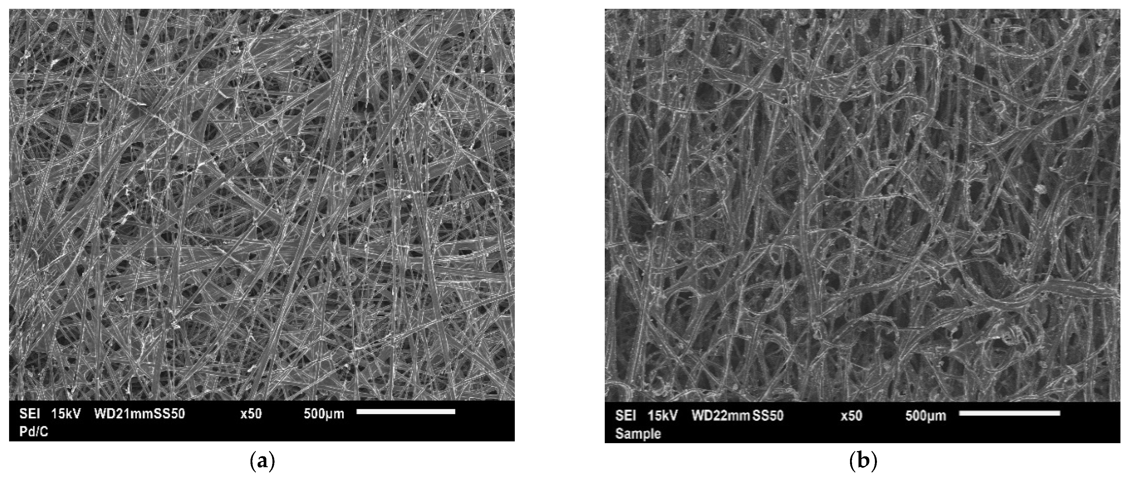
The average values of gas permeability, shown in Table 2, are in good agreement with those reported in the literature for similar substrates. Figure 3a,b shows the SEM images of the uncoated non-woven straight and felt-fibre paper GDLs, Toray TGP-H-60 and SGL 10DA, respectively.

3.2. Through-Plane Gas Permeability of Gas Diffusion Media

3.2.1. Effect of Ink Homogenisation Techniques

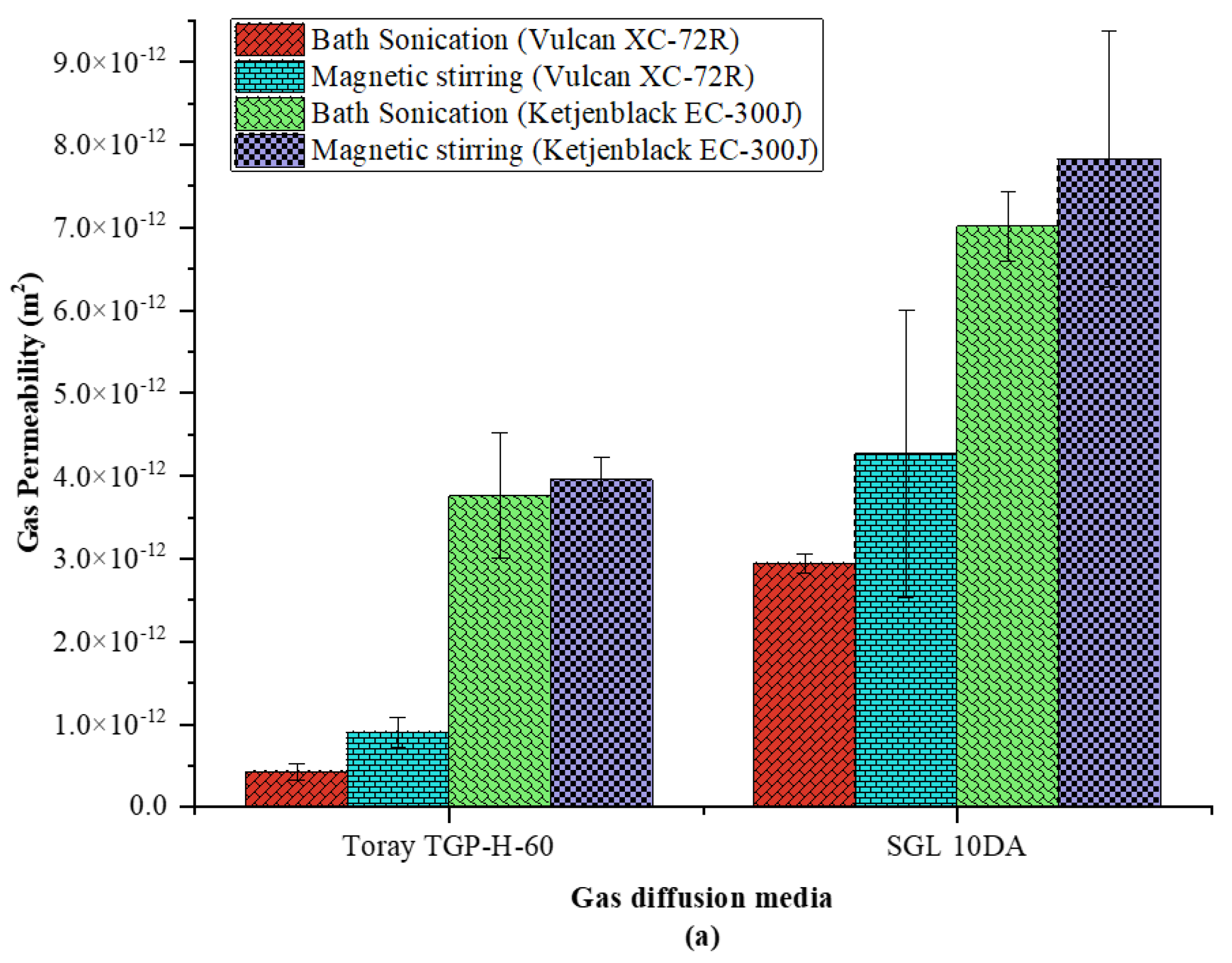
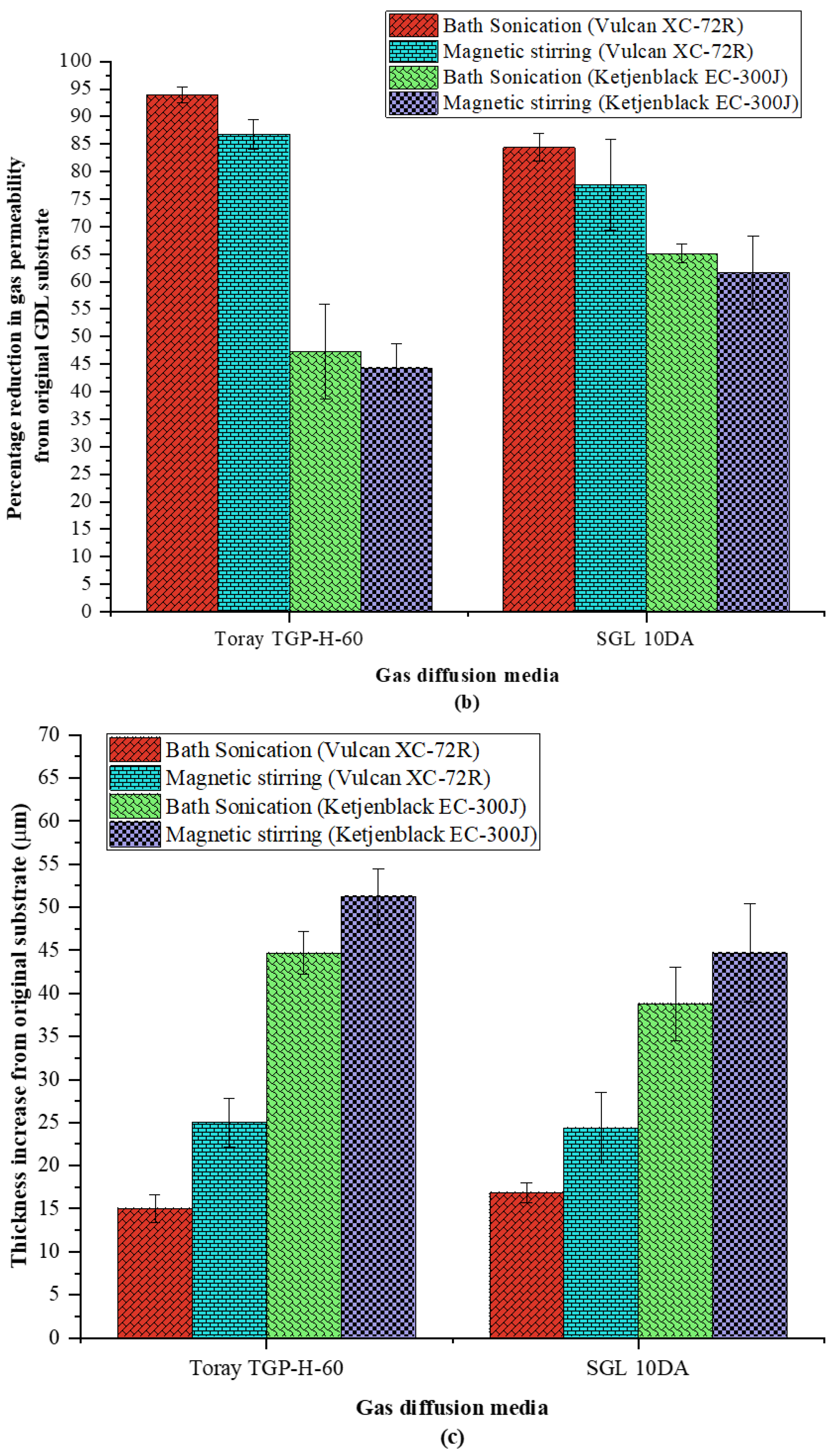
The through-plane gas permeability of the GDM was investigated and reported in this section for two carbon powders (Vulcan XC-72R and Ketjenblack EC-300J) and two ink homogenisation techniques (bath sonication and magnetic stirring) for a constant homogenisation time of two hours. GDM gas permeability was calculated in a similar manner to that of the GDL samples using Darcy’s law. Figure 4 illustrates the linear relationship between the pressure gradient across the GDM as a function of the fluid velocity for the GDM created using the two homogenisation techniques. As shown in Figure 4a,b the pressure gradient is higher for samples coated with Vulcan XC-72R, independent of the GDL structure or homogenisation technique; however, carbon felt-fibre GDMs have a lower pressure gradient, which is reflected in the increase in gas permeability, as shown in Figure 5a. Figure 5 shows the comparison of the results of the through-plane gas permeability and thickness increase in the GDL substrates after coating the substrates with two different carbon powders (Vulcan XC-72R and Ketjenblack EC-300J), utilising two different ink homogenisation techniques in MPL preparation (bath sonication and magnetic stirring). The error bars represent the 95% confidence interval about the mean for four samples. The surface morphology of the GDM using the different homogenisation techniques and structured GDLs are shown in Figure 6.
As shown in Figure 5a, the through-plane gas permeability of the GDM increases using magnetic stirring as the homogenisation method, independent of the type of GDL substrate and carbon powder used. The through-plane gas permeability increases by a factor of ~2 and 1.5 for MPLs composed of Vulcan XC-72R coated onto Toray TGP-H-60 and SGL 10DA, respectively, when using magnetic stirring over bath sonication compared to an increase of ~1.1 for MPLs composed of Ketjenblack EC-300J. In other words, the effects of magnetic stirring are more apparent for a low-surface-area carbon powder MPL (Vulcan XC-72R) and have an almost negligible impact on the through-plane gas permeability for a high-surface-area carbon powder MPL (Ketjenblack EC-300J), as shown in Figure 5b. Zhiani et al. [25] indicated that magnetic stirring required a longer period of homogenisation, such that, for a given homogenisation time, magnetic stirring would result in larger aggregates of carbon and PTFE, which would have resulted in a less compact MPL containing larger pores, which, subsequently, lead to an increase in through-plane gas permeability. It is interesting that the increase in through-plane gas permeability due to magnetic stirring is almost negligible for MPLs composed of Ketjenblack EC-300J, despite the larger surface cracks shown in Figure 6d,h compared to less cracked, smoother surfaces produced by bath sonication, shown in Figure 6c,g. Furthermore, there were no discernible differences in the surface morphologies of the MPLs composed of Vulcan XC-72R for the two homogenization techniques, despite the higher increase in through-plane gas permeability of the GDM. This would imply that the change in the size of the aggregates of carbon and PTFE formed within the MPL, due to magnetic stirring, was larger for low-surface-area Vulcan XC-72R compared with that of high-surface-area Ketjenblack EC-300J for the two hour homogenisation time, resulting in the higher increase in through-plane gas permeability. Lastly, larger aggregates of carbon and PTFE in the MPL ink dispersion due to magnetic stirring, result in an increase in MPL thickness, as shown in Figure 5c, due to the inability of the aggregates to penetrate further into the pores of the GDL during the coating process.
It is understandable from the surface morphologies shown in Figure 6 that the through-plane gas permeability of the GDM, shown in Figure 5a, is much higher for the substrates coated with Ketjenblack EC-300J, due to the large cracks formed on the MPL surface. The structure of the GDL plays an influential role in the thickness and morphologies for the GDM [6]. Namely, due to the lower porosity of Toray TGP-H-60 (around 63% as reported in [17]) compared to SGL 10DA (84% as reported in [28]), it was clearly shown that (for MPLs composed of Vulcan XC-72R) the aggregates of carbon and PTFE coated the surface of Toray TGP-H-60 completely (Figure 6a) and the surface of SGL 10DA partially (Figure 6e). As such, it would have been expected that the thickness increase in Toray TGP-H-60 would be higher than that of SGL 10DA, as seen in the case with Ketjenblack EC-300J. This is, however, not the case, as shown in Figure 5c, where the GDM composed of Vulcan XC-72R coated onto SGL 10DA is relatively similar to that of Toray TGP-H-60 for both techniques. Neehall et al. [6] reported a thickness increase of ~14–16 μm for SGL 10CA and SGL 10EA coated with Vulcan XC-72R for a carbon loading of 1.0 mg cm−2 and ~8–10 μm for Toray TGP-H-90 and Toray TGP-H-120, respectively, for an MPL ink sonication time of three hours. It was expected, as discussed in the subsequent section, that a decrease in ink homogenisation time would increase the size of the aggregates resulting in a thicker GDM. As shown in Figure 5c, SGL 10DA increases by ~17 μm and Toray TGP-H-60 increases by 15 μm when coated with Vulcan XC-72R for an MPL ink sonication time of two hours. The change in thickness (compared with previous results) is, therefore, higher for the lower porosity GDL (Toray TGP-H-60), as expected, and highlights the importance of homogenisation time, which is discussed in the subsequent section.

3.2.2. Impact of Homogenisation Time

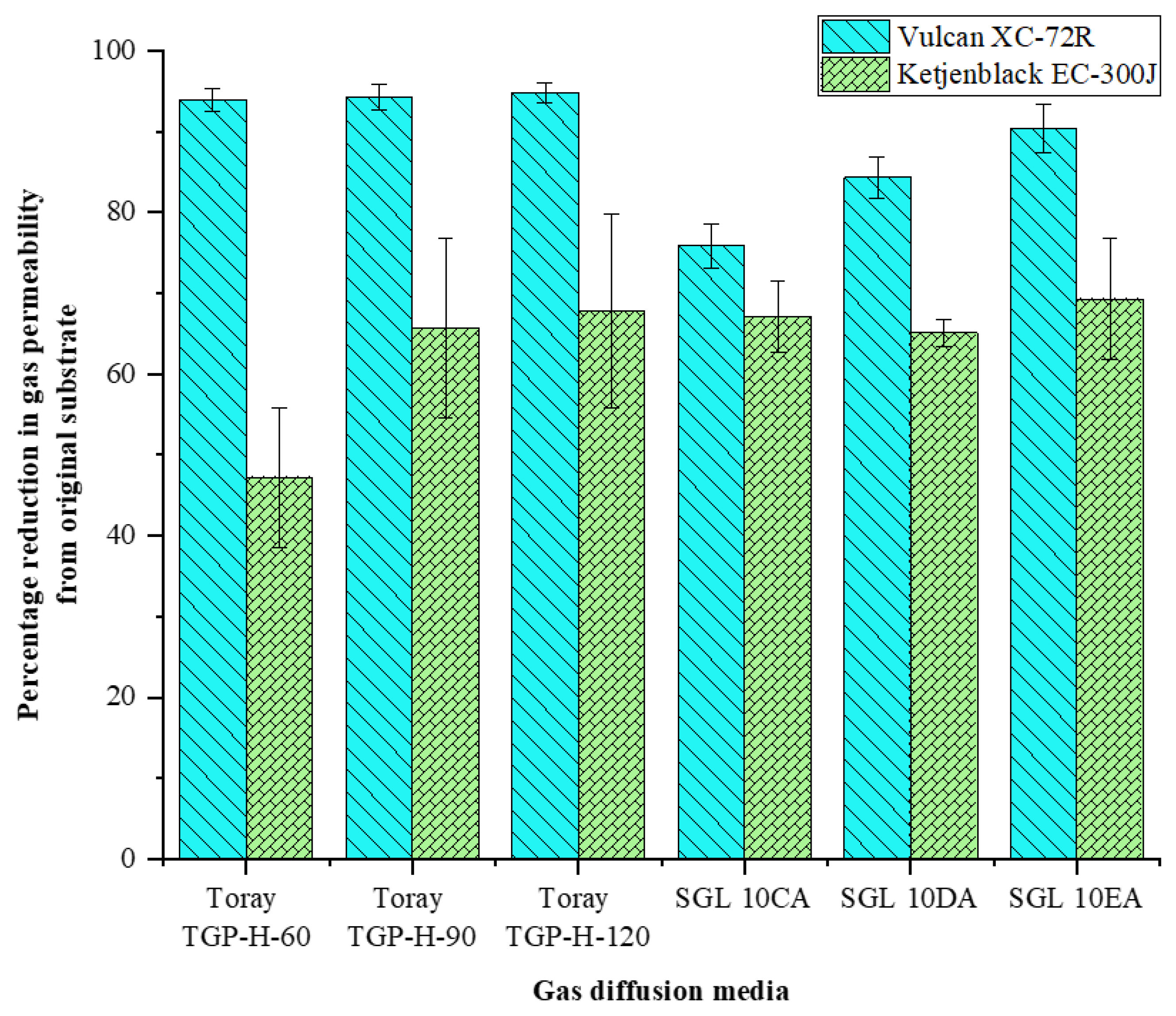
The results from the previous section were compared with those reported in Ref. [6] for GDM comprised of similarly structured GDLs and carbon powders. The MPL composition was kept constant in both studies at 80 wt.% carbon and 20 wt.% PTFE for a carbon loading of 1.0 mg cm−2. It should be noted that the MPL ink slurry used in the coating process in Ref. [6] was homogenised using bath sonication for a period of three hours. Figure 7 shows the comparison of the results. The error bars represent the 95% confidence interval about the mean.
Neehall et al. [6] indicated that GDLs of a similar structure showed predictable reductions in through-plane gas permeability, regardless of the carbon loading, when coated with an MPL, for a given carbon powder. As such, it was expected that the reduction in gas permeability for Toray TGP-H-60 would be similar to that of Toray TGP-H-90 and Toray TGP-H-120, and SGL 10DA to fall within a range between SGL 10CA and SGL 10EA for both carbon powders. For carbon felt-fibre paper GDLs, such as SGL 10DA, the results show predictable reductions in gas permeability for both carbon powders, despite the difference in homogenisation time used in the two investigations. The percentage reduction in gas permeability for SGL 10DA coated with Ketjenblack EC-300J is slightly lower (65%) than the range of 67–69% (SGL 10CA and SGL 10EA, respectively), which is the result of the lower homogenisation time. Furthermore, the difference in homogenisation time for MPLs composed of Vulcan XC-72R does not have any significant effect on the reduction in gas permeability for the two structured GDLs used. As such, an increase in ink homogenisation time would be expected to have an insignificant effect on the percentage reduction in gas permeability for GDM composed of a MPL containing Vulcan XC-72R.
The percentage reduction in through-plane gas permeability from the original substrate is, however, significantly lower (47%) for Toray TGP-H-60 compared to Toray TGP-H-90 (66%) and Toray TGP-H-120 (68%) when coated with Ketjenblack EC-300J. Figure 8 shows a comparison of the gas permeability, percentage reduction in through-plane gas permeability from the original substrate for Toray TGP-H-60 coated with Vulcan XC-72R and Ketjenblack EC-300J, and thickness increase in the samples between ink homogenisation times of two and three hours. Investigations of homogenisation time were not performed for SGL 10DA due to unavailability of samples; however, based on the results shown in Figure 7, it is expected that an increase in homogenisation time by one hour would have an insignificant effect on the reduction in through-plane gas permeability for both carbon powders, due to the higher porosity of SGL 10DA compared with Toray TGP-H-60. Figure 9 shows the SEM images for Toray TGP-H-60 coated with Vulcan XC-72R and Ketjenblack EC-300J for an ink homogenisation time of three hours.
The surface morphology shown in Figure 9a,b indicates that the increase in homogenisation time of one hour results in smoother, less cracked MPL structures when compared with those of Figure 6a,c for both carbon powders, which is reflected by the reduction in through-plane gas permeability. Furthermore, the increase in homogenisation time of one hour greatly reduced the frequency of cracks on the MPL surface for the GDM composed of Ketjenblack EC-300J, which would account for the considerable reduction in gas permeability between the two- and three-hour ink homogenisation times. As such, the homogenisation time should be considered for high-surface-area carbon powders, such as Ketjenblack EC-300J, during the preparation of the MPL ink mixture. Lastly, as shown in Figure 8c, the increase in ink homogenisation time results in lower thickness increases for both carbon powders, which suggests that, similar to the type of homogenisation technique used, the time influences the size of aggregates of carbon and PTFE in the MPL ink. Lower homogenisation times resulted in larger aggregates of carbon and PTFE, which were unable to penetrate the pores of the GDL, resulting in an increase in thickness of the GDM.

4. Conclusions

The through-plane gas permeability, thickness, and surface morphology of the GDM using two different structured GDLs were investigated for MPLs derived from two different ink homogenisation techniques: (i) bath sonication and (ii) magnetic stirring. The impact of homogenisation techniques on different surface area carbon powders (Vulcan XC-72R and Ketjenblack EC-300J) was investigated for a carbon loading of 1.0 mg cm−2 and an MPL composition of 80 wt.% carbon powder and 20 wt.% PTFE. The results of the MPLs derived from bath sonication were compared with previous investigations by the authors, to determine the impact of the MPL ink homogenisation time on the through-plane gas permeability, thickness, and surface morphology of the GDM. The following are the main conclusions:
  • Bath sonication produced MPLs with a smoother surface and less cracks when compared with the surface morphology produced using magnetic stirring for a high-surface-area carbon powder (Ketjenblack EC-300J). There were no discernible differences in the surface morphology between the two homogenisation techniques for a low-surface-area carbon powder (Vulcan XC-72R);
  • Magnetic stirring resulted in an increase in through-plane permeability by a factor of 1.5 to 2 for MPLs composed of Vulcan XC-72R when coated on SGL 10DA and Toray TGP-H-60, respectively. The resulting increase in through-plane gas permeability was attributed to larger aggregates of carbon and PTFE being formed due to the technique used. The homogenisation technique also influenced the thickness of the MPL, where magnetic stirring resulted in thicker structures independent of the GDL substrate;
  • The impact of magnetic stirring is more apparent on the through-plane gas permeability for low-surface-area carbon powder (Vulcan XC-72R) and on the surface morphology of high-surface-area carbon powder (Ketjenblack EC-300J);
  • Carbon felt-fibre paper (SGL 10DA) GDM showed predictable reductions in through-plane gas permeability for the two carbon powders when compared to previous investigations for SGL 10CA and SGL 10EA, despite a decrease in bath sonication time of one hour. This was attributed to the higher porosity of the carbon felt-fibre paper GDL;
  • MPL ink sonication time of three hours resulted in a percentage reduction in through-plane gas permeability from the GDL substrate permeability by 72% for high-surface-area carbon powder (Ketjenblack EC-300J) compared to 47% for a two-hour sonication time; there was a negligible difference in the percentage reduction in through-plane gas permeability between the two bath sonication times for MPLs composed of low-surface-area carbon powder (Vulcan XC-72R).
The results of the investigations in this study reveal how significant MPL properties are influenced by the type of carbon powder, homogenisation technique, and time required to produce a well-dispersed ink mixture. Furthermore, the results presented in this investigation show that the GDL structure, carbon powder type, and homogenisation technique and time can be adjusted to achieve a desirable GDM structure. The findings presented in this study will serve as a foundation for future research aimed at exploring the effects of cracks in the MPL on PEFC performance. While it is anticipated that the MPL with higher through-plane gas permeability will lead to improved fuel cell performance, experimental verification is still required to confirm this hypothesis.

Author Contributions

N.D.N.: conceptualisation, methodology, formal analysis, investigation, validation, writing—original draft, writing—review and editing, and visualisation. M.S.I.: conceptualisation, methodology, formal analysis, investigation, validation, writing—original draft, writing—review and editing, and supervision. K.J.H.: supervision, and writing—review and editing. M.P.: supervision, writing—review and editing, and project administration. All authors have read and agreed to the published version of the manuscript.

Funding

This research received no external funding.

Data Availability Statement

Data are available upon reasonable request.

Acknowledgments

The first author gratefully acknowledges the financial support of the Scholarships and Advanced Training Division (SATD) within the Ministry of Education in the Republic of Trinidad and Tobago. The authors would like to thank Alan Dunbar from the G67 SEM laboratory at the University of Sheffield for use of the facilities and the Cabot Corporation (USA) for supplying the Vulcan XC-72R which was used in this work.

Conflicts of Interest

The authors declare no conflict of interest.

References

  1. Ismail, M.S.; Damjanovic, T.; Hughes, K.; Ingham, D.B.; Ma, L.; Pourkashanian, M.; Rosli, M. Through-Plane Permeability for Untreated and PTFE-Treated Gas Diffusion Layers in Proton Exchange Membrane Fuel Cells. J. Fuel Cell Sci. Technol. 2010, 7, 051016. [Google Scholar] [CrossRef]
  2. Ismail, M.; Borman, D.; Damjanovic, T.; Ingham, D.; Pourkashanian, M. On the through-plane permeability of microporous layer-coated gas diffusion layers used in proton exchange membrane fuel cells. Int. J. Hydrogen Energy 2011, 36, 10392–10402. [Google Scholar] [CrossRef]
  3. Orogbemi, O.; Ingham, D.; Ismail, M.; Hughes, K.; Ma, L.; Pourkashanian, M. The effects of the composition of microporous layers on the permeability of gas diffusion layers used in polymer electrolyte fuel cells. Int. J. Hydrogen Energy 2016, 41, 21345–21351. [Google Scholar] [CrossRef]
  4. Orogbemi, O.; Ingham, D.; Ismail, M.; Hughes, K.; Ma, L.; Pourkashanian, M. Through-plane gas permeability of gas diffusion layers and microporous layer: Effects of carbon loading and sintering. J. Energy Inst. 2018, 91, 270–278. [Google Scholar] [CrossRef]
  5. Mukherjee, M.; Bonnet, C.; Lapicque, F. Estimation of through-plane and in-plane gas permeability across gas diffusion layers (GDLs): Comparison with equivalent permeability in bipolar plates and relation to fuel cell performance. Int. J. Hydrogen Energy 2020, 45, 13428–13440. [Google Scholar] [CrossRef]
  6. Neehall, N.D.; Ismail, M.S.; Hughes, K.J.; Pourkashanian, M. Effect of composition and structure of gas diffusion layer and microporous layer on the through-plane gas permeability of PEFC porous media. Int. J. Energy Res. 2021, 45, 20988–21005. [Google Scholar] [CrossRef]
  7. Li, C.; Si, D.; Liu, Y.; Zhang, J.; Liu, Y. Water management characteristics of electrospun micro-porous layer in PEMFC under normal temperature and cold start conditions. Int. J. Hydrogen Energy 2021, 46, 11150–11159. [Google Scholar] [CrossRef]
  8. Bae, I.; Kim, B.; Kim, D.-Y.; Kim, H.; Oh, K.-H. In-plane 2-D patterning of microporous layer by inkjet printing for water management of polymer electrolyte fuel cell. Renew. Energy 2020, 146, 960–967. [Google Scholar] [CrossRef]
  9. Yang, Y.; Zhou, X.; Li, B.; Zhang, C. Recent progress of the gas diffusion layer in proton exchange membrane fuel cells: Material and structure designs of microporous layer. Int. J. Hydrogen Energy 2021, 46, 4259–4282. [Google Scholar] [CrossRef]
  10. Zhang, Z.; He, P.; Dai, Y.-J.; Jin, P.-H.; Tao, W.-Q. Study of the mechanical behavior of paper-type GDL in PEMFC based on microstructure morphology. Int. J. Hydrogen Energy 2020, 45, 29379–29394. [Google Scholar] [CrossRef]
  11. Froning, D.; Reimer, U.; Lehnert, W. Inhomogeneous Distribution of Polytetrafluorethylene in Gas Diffusion Layers of Polymer Electrolyte Fuel Cells. Transp. Porous Media 2021, 136, 843–862. [Google Scholar] [CrossRef]
  12. Halvorsen, I.J.; Pivac, I.; Bezmalinović, D.; Barbir, F.; Zenith, F. Electrochemical low-frequency impedance spectroscopy algorithm for diagnostics of PEM fuel cell degradation. Int. J. Hydrogen Energy 2020, 45, 1325–1334. [Google Scholar] [CrossRef] [Green Version]
  13. Islam, M.N.; Shrivastava, U.N.; Atwa, M.; Li, X.; Birss, V.I.; Karan, K. Highly Ordered Nanoporous Carbon Scaffold with Controllable Wettability as the Microporous Layer for Fuel Cells. ACS Appl. Mater. Interfaces 2020, 12, 39215–39226. [Google Scholar] [CrossRef] [PubMed]
  14. Simon, C.; Kartouzian, D.; Müller, D.; Wilhelm, F.; Gasteiger, H.A. Impact of Microporous Layer Pore Properties on Liquid Water Transport in PEM Fuel Cells: Carbon Black Type and Perforation. J. Electrochem. Soc. 2017, 164, F1697–F1711. [Google Scholar] [CrossRef]
  15. Liu, C.; Li, S. Performance Enhancement of Proton Exchange Membrane Fuel Cell through Carbon Nanofibers Grown In Situ on Carbon Paper. Molecules 2023, 28, 2810. [Google Scholar] [CrossRef] [PubMed]
  16. Gostick, J.T.; Fowler, M.W.; Pritzker, M.D.; Ioannidis, M.A.; Behra, L.M. In-plane and through-plane gas permeability of carbon fiber electrode backing layers. J. Power Sources 2006, 162, 228–238. [Google Scholar] [CrossRef]
  17. El-Kharouf, A.; Mason, T.J.; Brett, D.J.; Pollet, B.G. Ex-situ characterisation of gas diffusion layers for proton exchange membrane fuel cells. J. Power Sources 2012, 218, 393–404. [Google Scholar] [CrossRef] [Green Version]
  18. Froning, D.; Drakselová, M.; Tocháčková, A.; Kodým, R.; Reimer, U.; Lehnert, W.; Bouzek, K. Anisotropic properties of gas transport in non-woven gas diffusion layers of polymer electrolyte fuel cells. J. Power Sources 2020, 452, 227828. [Google Scholar] [CrossRef]
  19. Aldakheel, F.; Ismail, M.; Hughes, K.; Ingham, D.; Ma, L.; Pourkashanian, M.; Cumming, D.; Smith, R. Gas permeability, wettability and morphology of gas diffusion layers before and after performing a realistic ex-situ compression test. Renew. Energy 2020, 151, 1082–1091. [Google Scholar] [CrossRef]
  20. Ismail, M.; Damjanovic, T.; Ingham, D.; Ma, L.; Pourkashanian, M. Effect of polytetrafluoroethylene-treatment and microporous layer-coating on the in-plane permeability of gas diffusion layers used in proton exchange membrane fuel cells. J. Power Sources 2010, 195, 6619–6628. [Google Scholar] [CrossRef]
  21. Williams, M.V.; Begg, E.; Bonville, L.; Kunz, H.R.; Fenton, J.M. Characterization of Gas Diffusion Layers for PEMFC. J. Electrochem. Soc. 2004, 151, A1173–A1180. [Google Scholar] [CrossRef]
  22. Gurau, V.; Bluemle, M.J.; De Castro, E.S.; Tsou, Y.-M.; Zawodzinski, T.A.; Mann, J.A. Characterization of transport properties in gas diffusion layers for proton exchange membrane fuel cells: 2. Absolute permeability. J. Power Sources 2007, 165, 793–802. [Google Scholar] [CrossRef]
  23. Pharoah, J.G. On the permeability of gas diffusion media used in PEM fuel cells. J. Power Sources 2005, 144, 77–82. [Google Scholar] [CrossRef]
  24. Mangal, P.; Pant, L.M.; Carrigy, N.; Dumontier, M.; Zingan, V.; Mitra, S.; Secanell, M. Experimental study of mass transport in PEMFCs: Through plane permeability and molecular diffusivity in GDLs. Electrochim. Acta 2015, 167, 160–171. [Google Scholar] [CrossRef]
  25. Zhiani, M.; Kamali, S.; Majidi, S. In-plane gas permeability and thought-plane resistivity of the gas diffusion layer influenced by homogenization technique and its effect on the proton exchange membrane fuel cell cathode performance. Int. J. Hydrogen Energy 2016, 41, 1112–1119. [Google Scholar] [CrossRef]
  26. Yuan, X.-Z.; Gu, E.; Bredin, R.; Baker, M.; Lee, S.; Biggs, T.; Bock, A.; Banhardt, V.; Russell, J.; Girard, F. Development of a 3-in-1 device to simultaneously measure properties of gas diffusion layer for the quality control of proton exchange membrane fuel cell components. J. Power Sources 2020, 477, 229009. [Google Scholar] [CrossRef]
  27. Ihonen, J.; Mikkola, M.; Lindbergh, G. Flooding of Gas Diffusion Backing in PEFCs: Physical and electrochemical characterization. J. Electrochem. Soc. 2004, 151, A1152–A1161. [Google Scholar] [CrossRef] [Green Version]
  28. Gostick, J.T.; Ioannidis, M.A.; Fowler, M.W.; Pritzker, M.D. Wettability and capillary behavior of fibrous gas diffusion media for polymer electrolyte membrane fuel cells. J. Power Sources 2009, 194, 433–444. [Google Scholar] [CrossRef]
  29. Neehall, N.D. Through-Plane Gas Permeability of Carbon-Based Porous Media in Polymer Electrolyte Fuel Cells. Ph.D. Dissertation, Mechanical Engineering, University of Sheffield, Sheffield, UK, 2019. Available online: https://etheses.whiterose.ac.uk/26987/1/PhD_Thesis-final-rev-NDNeehall-1.pdf (accessed on 20 June 2023).
  30. Mathias, M.F.; Roth, J.; Fleming, J.; Lehnert, W. Diffusion media materials and characterisation. Handb. Fuel Cells 2010, 3, 517–537. [Google Scholar] [CrossRef]
Figure 1. Schematic representation of the in-house built experimental setup for through-plane gas permeability measurements. Reprint from ref [2] with permission from Elsevier; Copyright 2011, International Journal of Hydrogen Energy.
Energies 16 05944 g001
Figure 3. SEM images of (a) Toray TGP-H-60 and (b) SGL 10DA [29].
Energies 16 05944 g003
Figure 4. Pressure gradient as a function of fluid velocity using two different ink homogenization techniques for (a) Toray TGP-H-60 and (b) SGL 10DA [29].
Energies 16 05944 g004
Figure 5. (a) Through-plane gas permeability, (b) percentage reduction in through-plane gas permeability and (c) thickness increase in the GDMs using different carbon powders and homogenisation techniques [29].
Energies 16 05944 g005aEnergies 16 05944 g005b
Figure 6. SEM images showing the surface morphology of the GDM coated with Vulcan XC-72R (a,b,e,f) and Ketjenblack EC-300J (c,d,g,h) on Toray TGP-H-60 (ad) and SGL 10DA (eh) using bath sonication (left) and magnetic stirring (right) [29].
Energies 16 05944 g006aEnergies 16 05944 g006b
Figure 7. Comparison of the percentage reduction in gas permeability from the original GDL substrate for Toray TGP-H-60, SGL 10DA and other GDM materials reported in [6] for a carbon loading of 1.0 mg cm−2 [29].
Energies 16 05944 g007
Figure 8. Comparison of the effect of ink homogenisation time using bath sonication on the (a) through-plane gas permeability, (b) percentage reduction in gas permeability of the GDM from the original substrate, and (c) thickness increase for Vulcan XC-72R and Ketjenblack EC-300J carbon powders [29].
Energies 16 05944 g008aEnergies 16 05944 g008b
Figure 9. SEM images showing the surface morphology of Toray TGP-H-60 coated with (a) Vulcan XC-72R and (b) Ketjenblack EC-300J for MPL ink homogenisation time of three hours [29].
Energies 16 05944 g009
Table 1. Manufacturers’ data for the GDLs and carbon powders.
PropertiesGas Diffusion Layer
Toray TGP-H-60SGL 10DA
Thickness (μm)190400
Areal weight (g m−2)-100
Porosity (%)7884 a
PTFE loading (%)520
PropertiesCarbon Powders
Ketjenblack EC-300JVulcan XC-72R
Pore volume (mL/100 g)310–345178
Apparent bulk density (kg m−3)125–14520–380
Surface area (m−2 g−1)950254
Particle diameter (nm)3030
a Ref. [28].
Disclaimer/Publisher’s Note: The statements, opinions and data contained in all publications are solely those of the individual author(s) and contributor(s) and not of MDPI and/or the editor(s). MDPI and/or the editor(s) disclaim responsibility for any injury to people or property resulting from any ideas, methods, instructions or products referred to in the content.