Review

A Survey on Multi-Active Bridge DC-DC Converters: Power Flow Decoupling Techniques, Applications, and Challenges

1
Power Electronics and Machines Centre (PEMC), School of Electrical and Electronics Engineering, University of Nottingham, Nottingham NG7 2GT, UK
2
Department of Electrical Engineering, Mathematics and Computer Science (EEMCS), University of Twente, 7500 AE Enschede, The Netherlands
*
Authors to whom correspondence should be addressed.
Energies 2023, 16(16), 5927; https://doi.org/10.3390/en16165927
Submission received: 15 June 2023 / Revised: 28 July 2023 / Accepted: 2 August 2023 / Published: 10 August 2023
(This article belongs to the Section F3: Power Electronics)

Abstract

:
Multi-port DC-DC converters are a promising solution for a wide range of applications involving multiple DC sources, storage elements, and loads. Multi-active bridge (MAB) converters have attracted the interest of researchers over the past two decades due to their potential advantages such as high power density, high transfer ratio, and galvanic isolation, for example, compared to other solutions. However, the coupled power flow nature of MAB converters makes their control implementation difficult, and due to the multi-input, multi-output (MIMO) structure of their control systems, a decoupling control strategy must be designed. Various control and topology-level strategies are proposed to mitigate the coupling effect. This paper discusses the operating principles, applications, methods for analyzing power flow, advanced modulation techniques, and small signal modelling of the MAB converter. Having explained the origin of cross-coupling, the existing power flow decoupling methods are reviewed, categorized, and compared in terms of effectiveness and implementation complexity.

1. Introduction

The replacement of fossil fuel-based energy sources with renewable energy systems (RES) and the transition to zero-emission electric vehicles (EV) is critical to decreasing the rate of global warming [1]. These systems cannot exist without energy storage components. Integrating energy storage systems (ESS) based on fuel cells (FC), batteries, and supercapacitors (SC) is required to increase the performance and reliability of RES [2]. Similarly, ESS is included in EVs to supply various loads. As a result, each application has several sources and loads, and power converters are in charge of transferring and controlling the power flow between them.
There are generally two methods for connecting multiple sources/loads. The first and most common way involves employing conventional two-port DC/DC converters. Nevertheless, because many converters must be installed and they cannot directly link all sources and loads, this strategy increases the number of power conversion stages and the ultimate cost of the system. Additionally, communication protocols between isolated converters are necessary for power management between two-port converters, which complicates the control and can reduce the overall system performance. When a larger number of sources/loads are added to the system, these difficulties become much more severe.
In recent years, multi-port DC/DC converters have been explored and proposed to overcome all of the issues generated by the use of individual two-port DC/DC converters in applications with multiple DC connections. In contrast to the traditional case, a multi-port converter can link all DC sources and loads directly to each other. As a result, in all operating modes, the conversion stage is reduced to one, resulting in decreased losses during power conversion. Furthermore, because multi-port topologies share a portion of the circuit among multiple ports, they contain fewer power components than standard two-port converters, resulting in a decrease in the total system cost, mass, and volume. Figure 1 displays two combined RES and ESS systems based on either multiple standard two-port DC/DC converters or a multi-port DC-DC converter. Figure 1a shows four two-port DC/DC converters used to connect photovoltaic (PV) panels, battery storage, and a multi-level inverter with multiple DC inputs. In Figure 1b, a five-port DC/DC converter replaces all the conventional DC/DC converters. It is evident that in the traditional architecture, the battery discharge process encounters two conversion steps, increasing system losses.
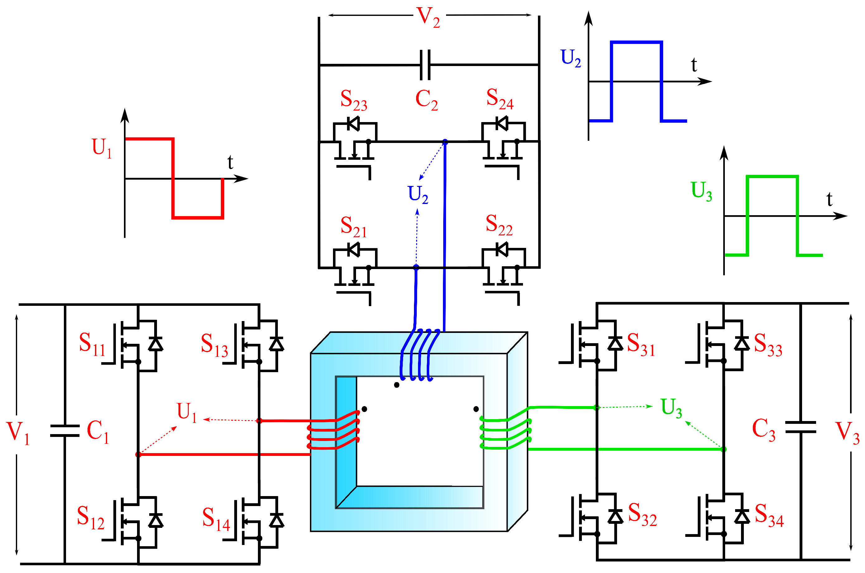
Several topologies for multi-port converters have been researched, depending on the application requirements. In terms of galvanic isolation, the topologies proposed can be divided into isolated and non-isolated multi-port converters. The multi-active bridge (MAB) converter, a natural extension of the dual-active bridge (DAB) converter, is the most prevalent architecture for multi-port DC/DC converters. The architecture of the MAB converter shown in Figure 2 was presented for the first time in [3,4], and incorporates active H-bridges coupled to a multi-winding high-frequency transformer. This MAB converter combines the benefits of the DAB converter, such as high power density, high gain, bidirectional power flow, and so on, with the general advantages of multi-port converters, such as reduced conversion stages, power component count, total cost, and losses.
The features and capability of the MAB converter have made it a suitable candidate for a wide range of applications and it has gained the interest of many researchers. MAB converters with different numbers of ports and their combination with other converters have been proposed for the following applications: hybrid energy storage (HESS) [4,5,6,7,8,9,10,11,12,13,14,15,16,17,18]; more electric aircraft (MEA) [19,20,21,22,23,24,25]; monopolar and bipolar DC grids [26,27,28,29,30,31,32,33,34]; Solid state transformer (SST) and modular transformer in microgrids, locomotive traction, EV charging, shipboards [35,36,37,38,39,40,41,42,43,44,45,46,47,48,49,50,51,52,53,54,55,56,57]; doubly fed induction generators (DFIG) in wind turbines [58]; unified power quality conditioner (UPQC) [59,60,61,62]; electric vehicle (EV) charging [63,64,65,66,67]; renewable energy systems (RES) such as PV modules integration with energy storage systems (ESS), microgrids or EV charging stations [68,69,70,71,72,73]; differential power processing converter for battery balancing, and data centers [74,75], uninteruptable power supply (UPS) [3,76]. Since a three-port MAB converter or triple active bridge (TAB) converter can meet the requirements in many applications, it is the most explored type of MAB converter [77]. However, depending on the application, adding more active bridges to achieve a higher number of ports has been proposed, resulting in the quadruple active bridge (QAB) [12,17,23,39,40,43,46,47,48,49,51,52,54,55,56,60,61,62,70,78,79,80,81,82,83,84,85,86,87,88,89,90], penta active bridge (PAB) [41], 6-port [91], 10-port [75], and 12-port [35,92,93] MAB converters.
Although adding more ports can provide potential advantages over the DAB converter, converter analysis becomes more complicated, and a research gap arises between the conventional DAB and the various MAB converters. Unlike the control of the DAB converter, which is straightforward and well-explored, the MAB converter has complicated control. Similar to all other multi-port converters, inherent control cross-coupling between each port is the cause of the control complexity. Sharing a part of the circuit among different ports reduces the total number of power components, and provides considerable merits; however, it causes inherent interaction between different ports. In other words, the control structure of a multi-port converter is a multi-input, multi-output (MIMO) system, and any change in one of the control loops also affects the other loops. In addition to complex control, steady-state analysis, power flow management, and achieving optimal power flow among the different ports can be challenging since more control variables appear in the system. Additionally, reliability and fault ride-through issues are more significant in MAB converters, because any fault or failure in one of the ports, negatively affects the other ports.
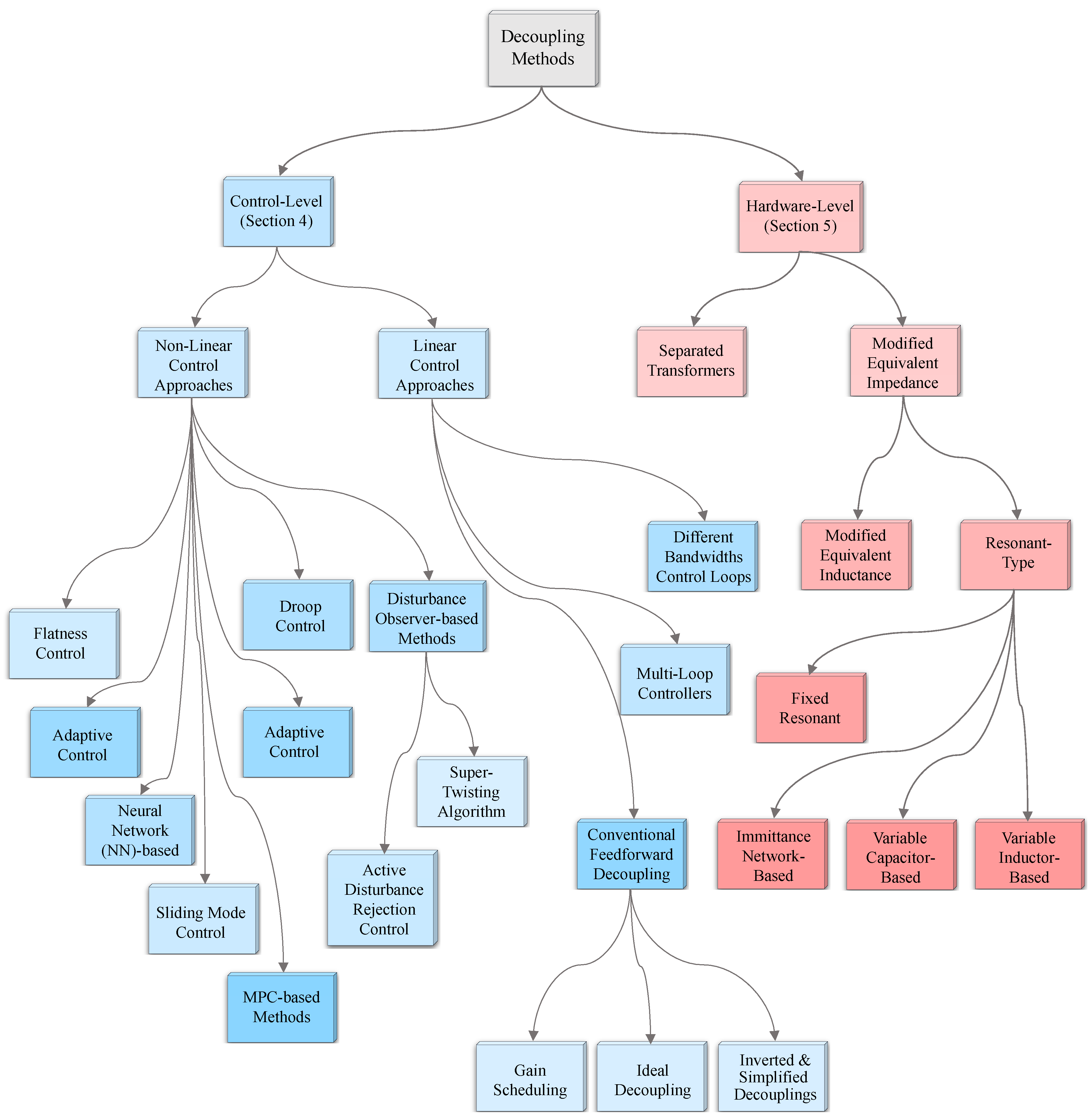
Since cross-coupling is a unique challenge in multi-port DC/DC converters, and it does not exist in two-port conventional structures for DC/DC converters, many researchers have focused on decoupling the power flow control between ports. Figure 3 demonstrates different proposed decoupling approaches for MAB converters. Using classic linear control theory, the interaction between control loops can be eliminated by storing the pre-calculated gain matrix inverse as an ideal feed-forward decoupling approach, allowing proportional-integral (PI) controllers to maintain the control outputs. However, this method has several drawbacks; it requires an accurate dynamic model of the converter, and, since decoupling terms are calculated for a specific operating point, a deviation in the operating point of the converter leads to non-optimal decoupling. Additionally, decoupling control design complexity grows exponentially with an increased number of ports, and also, the calculation and realization of the decoupling terms with ideal decoupling can be challenging. In general, ideal decoupling may lead to a poor transient response. To have simpler decoupling terms, some simplified decoupling schemes have been proposed which are discussed later; however, other drawbacks still remain.
To maintain optimal decoupling performance over a wide operating range, the work in [34] implemented a gain scheduling technique and feed-forward decoupling terms are tuned based on the operating region. The work presented in [58,94] proposed dual-loop and multi-loop-based controllers to reject the disturbance caused by interaction between loops, without the implementation of feed-forward decoupling terms. Although this approach can provide a more satisfactory transient response under step changes and uncertainties, the controller design is relatively more complicated. Other works in [15,95] proposed multi-loop controllers with different bandwidths to attenuate interaction between ports, with the highest bandwidth control loop determining the power flow. A combination of both conventional feed-forward decoupling and different bandwidth control loops is proposed in [17]. With all of the techniques mentioned above, it is difficult to achieve a fully decoupled control system, and they all have low to moderate dynamic responses.
Another approach, “time-sharing” is proposed in [83,93] and is an effective decoupling method, that shares the power-transfer interval of the common port with other ports, and at each time instant, only two ports are operating. However, this approach leads to higher output voltage ripple and current stress on devices. In addition, the power density decreases when more ports are included.
Because of the highly nonlinear behaviour of the MAB converter, some researchers have implemented different nonlinear robust control approaches. The works presented in [22,43,78] use model predictive control (MPC) to predict the current in future steps. Although these methods have excellent performance in terms of decoupling and can contain other constraints to have closer to optimal operation, they can incur a higher relative computational cost in a real-time implementation (especially if more degrees of freedom or control inputs are considered). In addition, the experimental tests and simulation results presented demonstrated slightly higher steady-state error in the control outputs compared to other approaches. The considerable merit of the proposed MPC-based approach in [22] is in having a decentralized control capability, which means the local information extracted from each submodule (port) can be used in the control process, and a local controller can regulate the output related to each submodule. Hence, unlike linear control-based approaches, the complexity of control design is independent of the number of ports.
Other researchers have aimed to solve the nonlinear control-to-output equations (online or offline), to implement effective decoupling over a wider range [35,52,96,97]. However, similar to MPC-based approaches, the computational cost of online calculation using iterative methods (e.g., Newton method) can be high, and having simplified iterative methods or lower iteration numbers can affect the accuracy and performance. Disturbance observer-based approaches are among other robust control methods proposed for decoupling control of MAB converter. In [84], an active disturbance rejection control (ADRC)-based control strategy is proposed which uses an extended state observer (ESO) for detecting any disturbance caused by external sources, coupling effect, or any kind of uncertainty, and a proportional differential (PD) compensator rejects the observed disturbance. Besides a relatively straightforward implementation and high robustness, the proposed ADRC method has a decentralized control structure. In [60], a super-twisting algorithm based on ESO is used. A combination of conventional decoupling and sliding mode control (SMC) is presented in [86]. Other researchers have proposed alternative solutions such as flatness control [98], black-box neural network (NN)-based approaches [21,91,99], and adaptive control [13,85,100], for example.
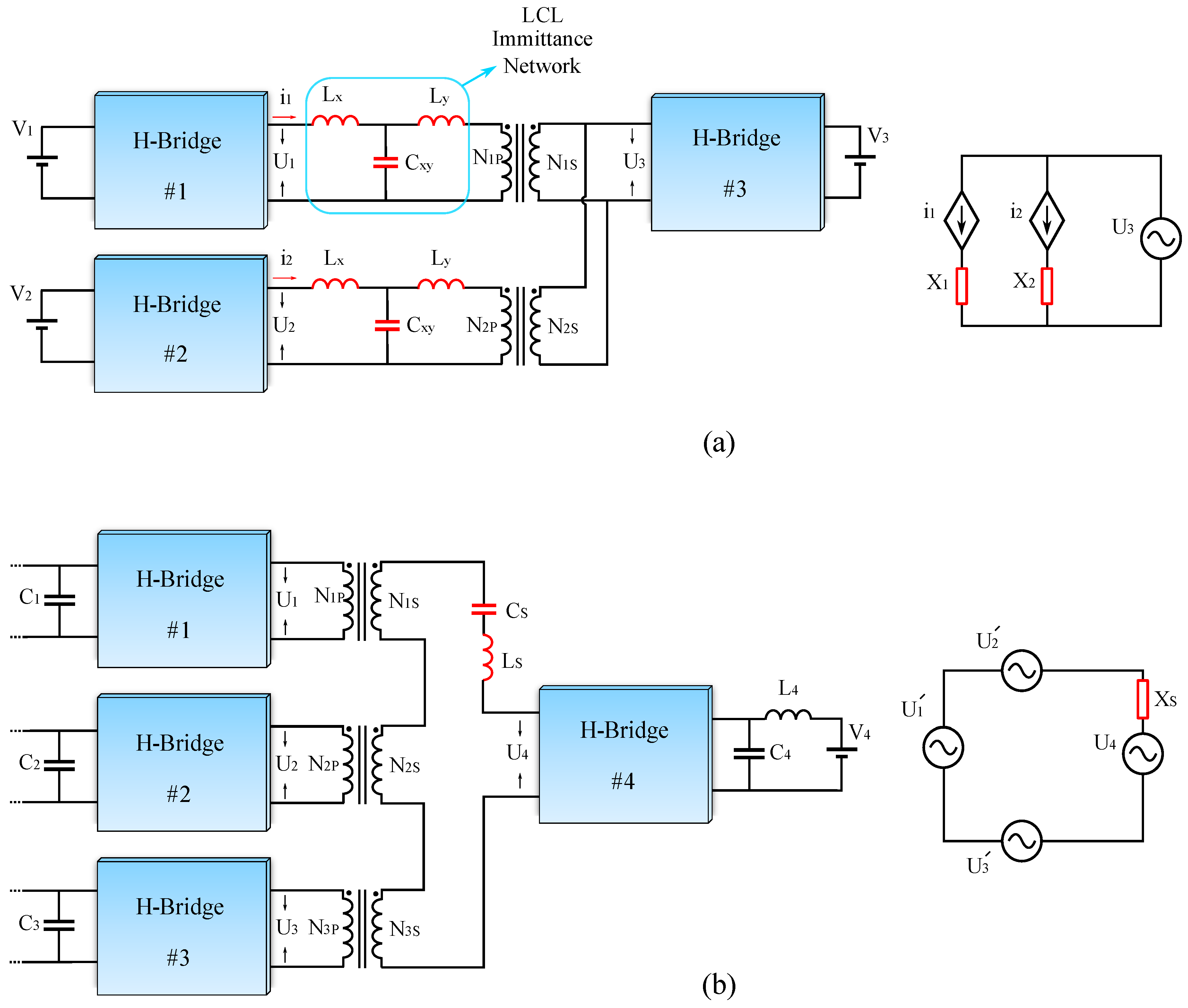
The different control approaches for power flow decoupling have a trade-off between complexity and dynamic performance. Hardware-level decoupling approaches are proposed to neglect the coupling effect at the circuit level, without employing complex control approaches. A series of resonant circuits connected with the winding of the common port can modify its equivalent impedance. By selecting the resonant frequency equal to the switching frequency, the resulting equivalent impedance will be close to zero, which means the power transfer is locally affected by the impedance of the other port [8,71,101,102,103]. However, since the common ports are predefined, achieving bidirectional power flow becomes challenging. To overcome limits on power flow direction, some researchers proposed adjustable resonant tanks using a variable “electronic capacitor” [6], and variable inductor [12], thus, the resonant frequency of the common port can be tuned based on the operating mode. Other researchers implemented an immittance network [104], or first harmonic synchronized (FHS) modulation [105], to extend bidirectional power flow capability in resonant-type decoupling approaches.
Modifying the equivalent inductance of each port by connecting auxiliary series-connected inductors also can decouple the power flow at the topology level [87,106,107]. However, the same power flow direction limits (especially for converters with a high number of ports) appear. This challenge can be overcome by adding one more leg to the bidirectional H-bridge, which enables bypassing or including the external inductor depending on the operating mode [88]. Other works proposed splitting the multi-winding transformer into several two-winding transformers, hence, the magnetic coupling will be eliminated [30,37,108,109]. In addition to reduced coupling, two-winding transformers have easier design and manufacturing. Using hardware approaches, each port can be controlled as an independent DAB converter by modifying the main topology of the MAB converter; however, these methods usually require more active or passive power components. It is worth mentioning that the proposed topology-based approaches are application-oriented mainly, and can provide advantages in specific applications.
In addition to complex cross-coupling behaviour in the MAB converter, steady-state analysis of the MAB converter is also more complicated than the DAB. The time-domain model is the conventional and most precise approach for steady-state analysis [110]. Unfortunately, when applied to more advanced modulation techniques with more degrees of freedom, time-domain analysis becomes extremely complicated. To overcome this, fundamental component analysis (FCA) has been proposed to simplify the steady-state design, ZVS criteria investigation, and optimization of the MAB converter [3,65,111,112,113]. However, higher-order harmonics of the square wave voltages and inductor currents are not taken into account which may lead to significant inaccuracy, especially with small phase shifts and/or small duty cycles that yield AC voltages rich in higher odd-order harmonics. Taking higher-order odd harmonics into account in a generalized harmonic analysis (GHA) can solve this problem [79,114,115,116,117]. Some other papers propose black-box model-free approaches to optimally operate the MAB converter without dealing with modelling complexities [99,118].
Many researchers have focused on other challenges in MAB converters, such as efficiency optimization by implementing advanced modulation techniques [9,11,61,63,65,72,79,85,99,110,118,119,120,121,122,123,124,125,126,127], and reducing conduction losses using wide bandgap semiconductors such as Silicon-carbide (SiC)-MOSFETs [39,82,128,129], or employing resonant circuits for reducing switching losses [130,131,132,133]. Others have explored fault ride through and analysis [5,32,50,53,81,134,135], electromagnetic interference, and high-frequency oscillation reduction [136] in MAB converters, these aspects are not reviewed or discussed in this paper.
Previous review papers on multi-port converters have mostly considered different topologies or have discussed suggested applications for multi-port converters, with none focusing on decoupling methodologies in MAB converters [2,137,138,139,140,141,142,143,144]. Triple-active bridge converters were briefly mentioned in [145]. The objective of this study is to investigate, categorize, and explain the merits and limitations of the various decoupling strategies that have been proposed. Furthermore, it provides an in-depth review of the MAB converter operating principles, modeling approaches, and modulation strategies. Section 2 discusses the principles of the MAB converter and explains the topology, steady-state equivalent circuit model (ECM), power flow analysis in the time domain, the fundamental component approach, and generalized harmonic analysis in the frequency domain. Section 3 discusses the dynamic and cross-coupling behaviour of the MAB converter. Section 4 of the paper explores and analyses the proposed linear and non-linear control-level decoupling approaches, while Section 5 discusses and compares topology-level power flow decoupling strategies of MAB converters.

2. Principles of the MAB Converter

This section explains and discusses the operating principles of a MAB converter. For simplicity of analysis, the triple active bridge (TAB) topology is considered. The topological arrangement, large-signal (steady-state) analysis under SPS modulation, dynamics, and small signal modeling of the TAB converter are covered in the following paragraphs.

2.1. Topology of the MAB Converter

The topology of the MAB converter is derived from the DAB converter. Figure 2. illustrates the topology of a TAB converter proposed in [3,4], and is constructed of three active H-bridges and a three-winding high-frequency transformer (HFT). H-bridges are connected to DC sources/loads on one side and generate three square wave AC voltage waveforms with variable relative phases. Each H-bridge is connected to one winding of the multi-winding HFT which is responsible for power transfer between ports. In addition, the HFT provides galvanic isolation and can step up or down the voltage levels depending on the turns-ratio. By varying the phase shifts between the square wave voltages, the magnitude and direction of the power flow between ports can be controlled. This topology for the TAB converter is extendable to an N-port MAB converter by adding more H-bridges and increasing the number of HFT windings.
One of the parameters used in steady-state design to calculate the power flow in DAB and MAB converters is the value of the series-connected inductance (leakage inductance). As a result, a good transformer design is necessary to obtain an appropriate value for the leakage inductance. The leakage inductance is mostly affected by the overlap of the windings, the core shape, and the air gap. In practice, normally there is no air gap in the AC transformer’s core to prevent excessive magnetizing current; therefore, positioning transformer windings is a more practicable means of adjusting leakage inductance. It is easier to tune the leakage inductance in a two-winding high-frequency transformer by adjusting the overlap between the two windings; however, because an MWHFT has more windings, it is more difficult to adjust the overlap between all windings and thus to achieve the desired value for all leakage inductances.
To address this problem, it is common to design an MWHFT with tight magnetic coupling between the windings, which leads to low leakage inductance, then external inductors are connected in series with each winding based on the steady-state design. In other words, from the practical point of view, the main topology of the MAB converter consists of series-connected external inductors. The work in [67] proposes a normalization design approach for the series-connected inductors in a three-port MAB converter. The work in [19] analyzes the leakage inductance in two-winding and three-winding transformers, and concludes, to have equal and tuned leakage inductances in an MWHFT, cores with symmetrical winding configurations such as toroidal cores are more appropriate, hence, the need for auxiliary series-connected inductors can be eliminated [99,118,127,146].
Many other topologies with different numbers of ports and power components are derived from the basic topology in Figure 2, for different proposes and applications, such as resonant MAB converters [130,131,132,133], and modular multi-active bridge (MMAB) converters [147,148,149,150]. These derived topologies are discussed further in the last section of the paper.

2.2. Equivalent Circuit Model of MAB Converter

Developing an Equivalent Circuit Model (ECM) is essential for analyzing the operating principles of the converter. There are two main parts in the ECM of the MAB converter, first, the model for the H-bridges, and second, the model for the multi-winding HFT. Since H-bridges generate square AC voltages ( U 1 , U 2 , , U n ), they can be simply modelled as square wave voltage sources. For the multi-winding HFT, various types of ECMs are investigated. The self/mutual inductance matrix is the most accurate model; however, direct and accurate measurements of the leakage inductance matrix elements are problematic. The work in [151] proposes a novel ECM for multi-winding HFTs, with directly measurable parameters. Among different ECMs for MWHFT, extended T, Pi, and cantilever models are the most popular ones, since they can provide sufficient accuracy and information about the characteristics of the HFT for steady-state analysis of the MAB converter. However, it is worth mentioning that the accuracy of these ECMs (extended T, Pi, cantilever) is affected by the physical geometry of the core and physical disposition of the windings, when there are more than three windings. Hence, some models may not have sufficient accuracy in some configurations of the MWHFT [152]. Review works in [153,154] provide more detailed information about different ECMs of the MWHFT.
ECM derivation of a TAB converter is depicted in Figure 4. There are a few steps to obtain the desired ECMs for the MAB converter:
  • MWHFT is replaced by one of the extended T, Pi, or cantilever ECMs.
  • Each H-bridge replaced by an AC voltage source ( U 1 , U 2 , , U n ).
  • Magnetizing inductance can be eliminated since it is much greater than the leakage inductance, and by referring parameters to the primary side, ideal transformers can be neglected, so a Star-type (Y-type) ECM will be achieved.
  • In order to directly link voltage sources to each other, a star to delta ( Y Δ ) transformation should be applied to achieve Δ -type ECM.
Neglecting the effect of magnetizing inductance considerably reduces design effort; however, this assumption may decrease the accuracy of the analysis. To take the effect of magnetizing inductance into account, the work in [155] decomposes the MAB converter ECM into several DAB converter ECMs. In other words, to analyze the power flow between all ports in a TAB converter, when magnetizing inductance is included, the ECM of the TAB can be decomposed into three DAB ECMs. Although this approach can provide more accuracy, it is not practical for a MAB with a greater number of ports ( 4 ,   5 , etc), since the number of resulting DAB ECMs will be high. As a conclusion, for MWHFT ECM, the extended Δ -type is the most appropriate ECM for power flow analysis in a MAB converter since it can directly connect ports to each other using linking inductances.

2.3. Power Flow Analysis

This part considers the steady-state performance of the MAB converter. Different modulation techniques and modelling approaches of the MAB converter are discussed.

2.3.1. Introduction to Modulation Techniques

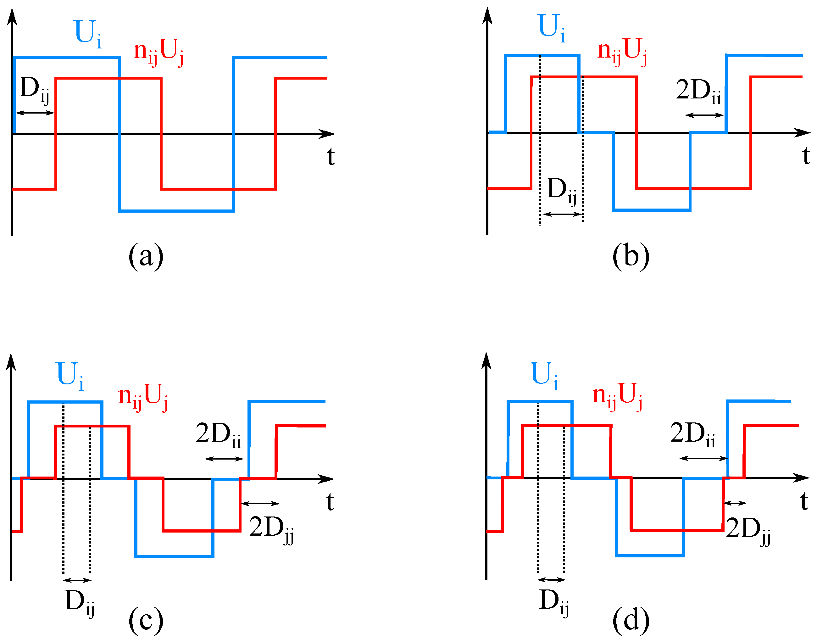
Various phase shift-based modulation strategies, illustrated in Figure 5, proposed for the DAB converter have been adapted for the MAB converter. The most conventional technique is the single phase shift (SPS) modulation approach. Each H-bridge is driven with a 50 % duty cycle to generate a square AC voltage. By modifying and adjusting the phase shift D i j between H-bridge i, and H-bridge j, the magnitude and direction of the power flow can be controlled. To add more degrees of freedom for controlling the power flow, and for optimizing the efficiency, more advanced modulation techniques such as extended phase shift (EPS) [156], dual-phase shift (DPS) [157], and triple phase shift (TPS) [158] modulation techniques have been investigated.
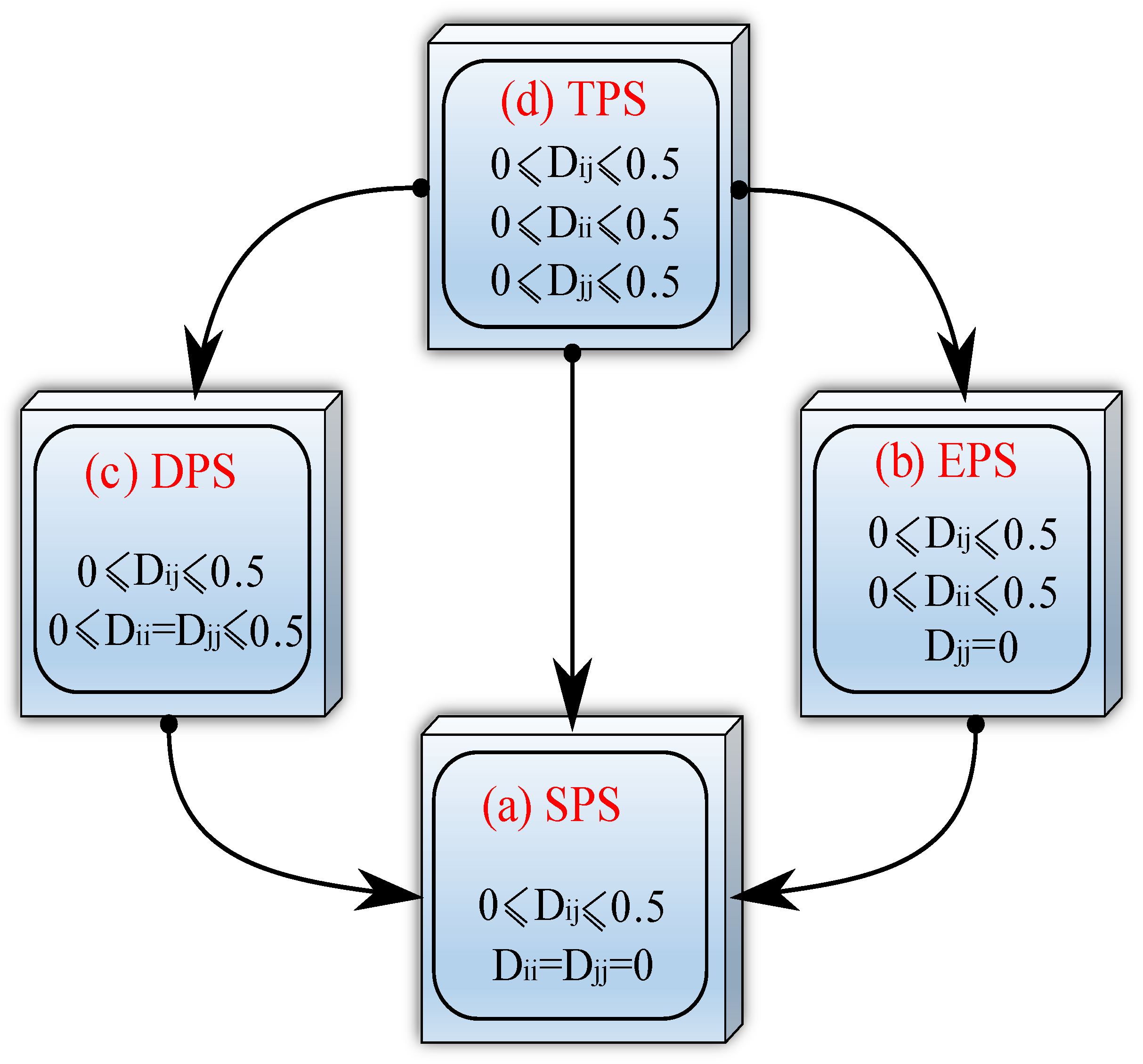
In the more advanced techniques, besides the outer phase shift (phase shift between bridges), an inner phase shift ( D i i for H-bridge i, and D j j for H-bridge j) between the H-bridge arms is used, which can vary the duty cycle of the square AC voltage from 0 to 50 % . In EPS, the inner PS is used only in one of the bridges D j j = 0 , while for DPS modulation, the same inner PS is used in all H-bridges D i i = D j j . TPS modulation is considered the most general modulation technique since it includes all other modulation techniques as special cases. In addition to the outer PS, each H-bridge can have a different inner phase shift to independently control the duty cycle of each square AC voltage. Figure 6 shows the correlation between the different schemes.
Since the DAB converter has just two H-bridges, the different modulation schemes are termed appropriately based on the number of phase shifts. However, this is not the case in the MAB (because of the increased number of bridges) which has led writers to use multiple names for the same modulation approach, which can be a source of confusion. The SPS and TPS techniques have received the most attention. In this paper, to avoid confusion, the term SPS is used if only outer phase shifts are considered, and the term general phase shift (GPS) is used if the inner phase shifts and the controllable duty ratio are considered.
Some other modulation techniques such as SPS (outer PS) plus symmetrical and asymmetrical duty cycles, and SPS plus variable frequency have also been applied to the MAB converter. The work in [64] proposes a new multi-pulse phase-modulation/duty cycle control for a TAB converter, where two bridges have the same switching frequency, and the third port has a different switching frequency. Proposed phase shift and frequency modulation could provide lower RMS current and independent power flow control. In addition, the implementation of wide bandgap power semiconductors has allowed for achieving higher switching frequencies (up to 220 kHz) and reducing the overall size and mass of the converter. In [105], a technique termed “first harmonic synchronized modulation” is implemented for the resonant TAB converter to achieve bidirectional decoupled power flow, and to achieve zero voltage switching in the entire operating range.
SPS is the most basic modulation technique; nevertheless, it has a limited soft-switching range, and the conduction losses can be adversely affected under some operating conditions, due to reactive power exchange. Advanced modulation techniques, like GPS, can overcome all of the aforementioned disadvantages and allow a greater degree of flexibility. The benefits of the advanced modulation techniques are as follows:
  • Expands ZVS criteria and reduces switching losses (especially under light loads) [117,124,124].
  • If the DC voltages are not equal (e.g.,: V i n i j V j ), using SPS modulation leads to unequal RMS value of the square AC voltages, which leads to reactive power, and more conduction losses. GPS modulation can modify and equalize the RMS values of the generated AC voltages and reduce or fully eliminate the reactive power. As a result, conduction losses are decreased [79,120,122,160].
  • Reduces peak value of the inductor current and provides lower current stress in components [53].
  • Under conventional SPS modulation, a DC offset appears in the AC current during transients (which decays slowly due to transformer resistance) and increases the settling time during transients. Advanced modulation techniques are capable of eliminating the inductor current DC offset in one switching cycle [43].
  • Advanced modulation strategies have more control freedom and can provide a more satisfactory transient response in comparison with conventional SPS modulation.
  • In terms of fault tolerance, advanced modulation approaches such as GPS have better performance, since they can bypass the short-circuit fault [32,57].
  • Using a small inner phase shift in GPS modulation can reduce high-frequency oscillations of the AC voltages and currents during the switching transient, and reduce the EMI [136].
  • In comparison with SPS modulation, GPS can increase the power flow capability between two ports by almost 30 % [157].

2.3.2. Modelling Approaches to Derive Power Flow Relationships

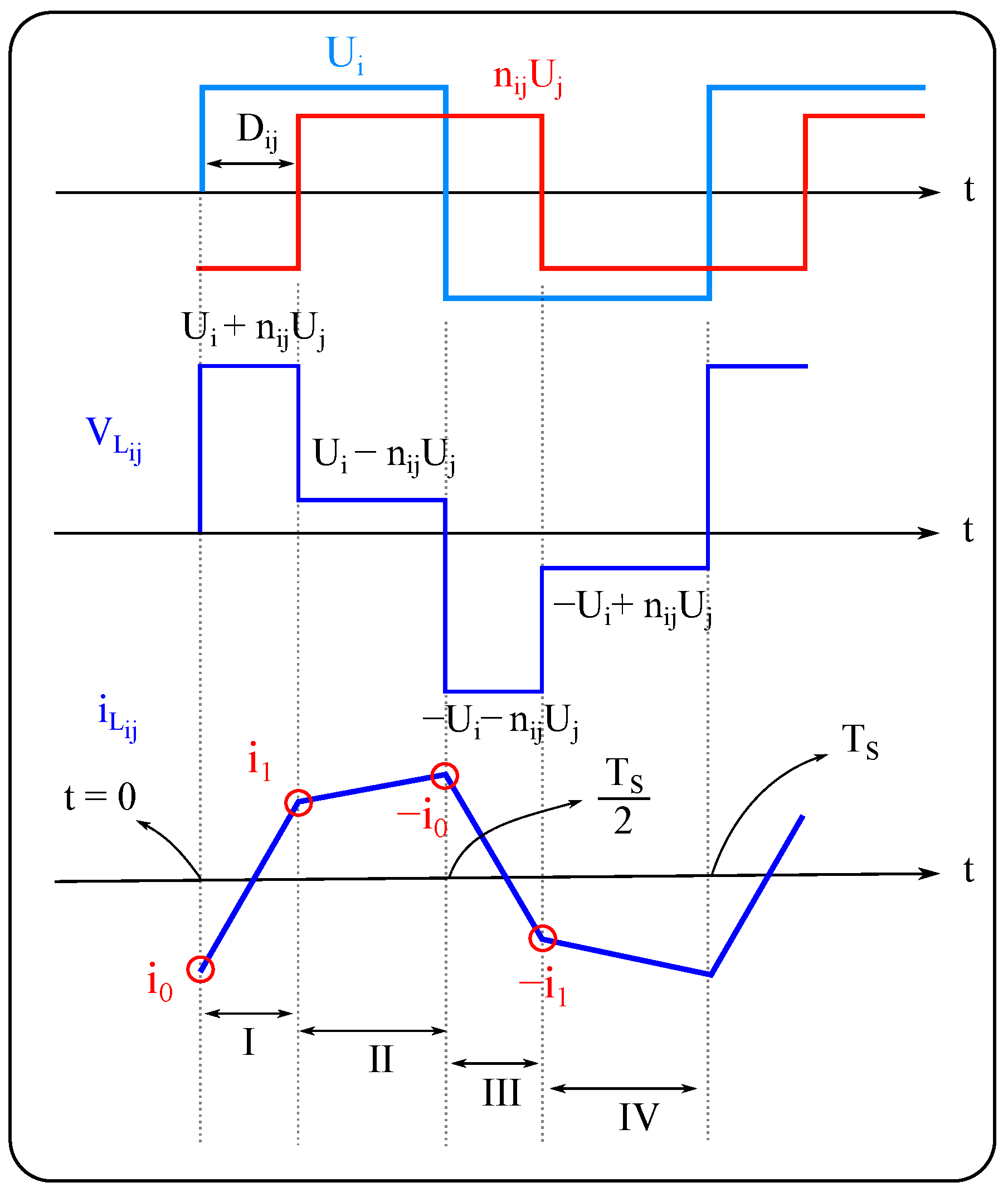
Time-domain analysis (TDA) is the most accurate approach for analyzing the power flow of a MAB converter. In order to find the power transfer between two ports i and j in the Δ -type ECM, the line inductance AC current, i L i j ( t ) , should be expressed as a function of two AC port voltages, U i , n i j U j , phase shift ratio D i j , switching frequency f s , and the value of line inductance between two ports L i j . The piecewise expression of the inductor current needs to be obtained. Figure 7 shows the two voltages, the inductor current, and the voltage drop across the inductance.
The inductor current is purely AC, and symmetric, so derivation of the current expression for a half-cycle is sufficient, hence:
I : i L i j ( t ) = i L ( 0 ) + ( U i + n i j U j ) t L i j I I : i L i j ( t ) = i L ( t 1 ) + ( U i n i j U j ) ( t t 1 ) L i j
i L i j ( 0 ) = ( U i n i j U j ) 2 n i j U j 4 f s L i j | D i j |
The power flow between port i and j ( P i j ) under SPS modulation using TDA is
P i j = 2 U i T s 0 T s 2 i L i j ( t ) d t n i j U i U j 2 f s L i j D i j ( 1 D i j ) , 1 2 D i j 1 2
where the sign of D i j determines the direction of power flow. And the maximum transferred power occurs at D i j = ± 1 2 .
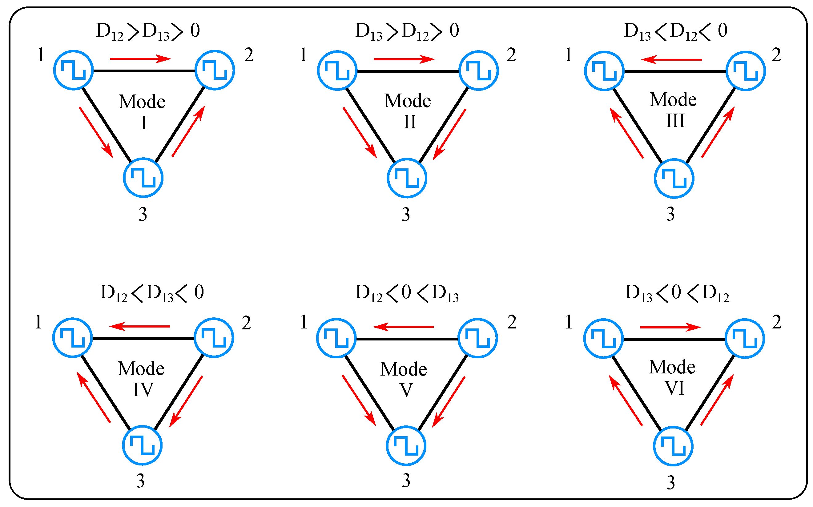
However, this result only determines the power transfer between two ports. Considering a TAB converter, different modes of power transfer with different phase shifts are possible as illustrated in Figure 8. Clearly, in any mode, the total power flow must sum to zero:
P 1 + P 2 + P 3 = 0
Although TDA provides all the information about the steady-state characteristics of a MAB converter, it is difficult to implement when complex modulation techniques (e.g., TPS modulation) are applied. In other words, using TDA, the analytical effort significantly increases by having more control variables. For example, in a TAB converter with all degrees of freedom (GPS modulation), 720 different voltage patterns appear, which need to be analyzed to find the optimum values. The work in [110] presented a TDA of a TAB converter with all degrees of freedom for multi-objective optimization, while the work in [35] performed a time-domain analysis for a 12-port MAB converter with all degrees of freedom for optimization with experimental validation.
Frequency-domain analysis (FDA) is a convenient approach to remove the need for piecewise calculation in TDA. A Fourier series can analytically represent the periodic AC voltages and currents. Figure 9 illustrates the different components of two square voltages and the current between them for general phase shift modulation (all degrees of freedom). Their phasor diagram is demonstrated in Figure 9b. The voltages and current amplitudes can be expressed as follows, where k is the harmonic order, ϕ i j is the outer phase shift between the i and j ports, and δ i and δ j represent the inner phase shift of the i and j H-bridge, respectively:
U i , k = 4 U i cos ( k δ i ) k π , k = 1 , 3 , 5 , 7 , , U j , k = 4 n i j U j cos ( k δ j ) k π , k = 1 , 3 , 5 , 7 , , i i j , k = U i , k 2 + U j , k 2 2 U i , k U j , k cos ( k ϕ i j ) 2 π k f s L i j , k = 1 , 3 , 5 , 7 , , π 2 ϕ i j π 2
The power transferred between the two ports is given by the following expression where 2 m + 1 is the highest odd-order component that is considered:
P i j = k = 1 2 m + 1 U i , k U j , k sin ( k ϕ i j ) 4 k π f s L i j , k = 1 , 3 , 5 , 7 , , π 2 ϕ i j π 2
Taking only the first harmonic into account considerably reduces the computational effort of steady-state analysis and, consequently, many papers consider only fundamental frequency analysis (FCA) [3,65,111,112,113]. The FCA can be imprecise since the higher odd-order components of the waveforms are not taken into account for power flow calculation (and the error can be considerable in some conditions), thus, its use is mostly limited to resonant-type MAB converters. Summation of more higher-order odd components, and using general harmonic analysis (GHA) can solve the problem of FCA. However, with increasing harmonic order, the amplitudes and contribution to power transfer decay quickly so, for an efficient calculation, it is important to decide where to truncate the series. Generally, taking up to the 11th harmonic component can provide sufficient accuracy for modelling the behaviour of the MAB converter, and for optimization [124].
Some researchers have proposed model-free approaches for the optimal operation of the MAB converter. The work in [118] proposes a three-dimensional ripple correlation control (RCC) technique for a TAB converter with five degrees of freedom (two outer and three inner phase shifts), and a three-dimensional RCC search for the optimal value of the three inner phase shifts ( δ 1 , δ 2 , δ 3 ). Relatively simple implementation, online operation, and robustness of the approach to uncertainties of the circuit parameters are the main advantages of this approach. In the work in [11] a deep learning-based algorithm is implemented, and is trained by measurement data. Similarly in [146], an artificial neural network (ANN) is trained to determine the optimal inner phase shifts. Although model-free approaches are robust, they are not a general unified method to study and analyze the operating principles of the MAB converter, and they can be considered black-box approaches that bypass modelling and design complexities. Table 1 briefly compares the advantages and disadvantages of the four methods mentioned above (TDA, FCA, GHA, and model-free).

3. Dynamics and Small Signal Modelling

This section discusses the dynamic behaviour of the MAB converter. For this purpose, a small signal model of the MAB converter is required. Steady-state power flow equations derived using different approaches such as TDA, FCA, and GHA can be used to establish the small signal model. The physical origins and mathematical explanation of the cross-coupling effect and the interaction between control loops are represented. Finally, different control and topology-level decoupling techniques regarding effectiveness, robustness, and implementation complexity are discussed and compared.
State-space averaging is a popular and effective tool to analyze and demonstrate the dynamic behaviour of the MAB converter. The filter capacitor voltages and the transformer/inductor currents can be selected as the state variables. However, the inductor current is purely AC, and its average in a period will be zero. Hence, the dynamics of the inductor can be ignored in the analysis, and because the dynamics of the capacitors are dominant, only filter capacitors are considered. The thesis work in [167] used a discrete-time half-cycle averaging of the inductor current and demonstrated that the dynamic effect of the inductors appears at high frequencies, causing a right half-plane (RHP) zero close to the switching frequency. Consequently, the assumption (neglecting the dynamics of the inductors) is reasonable, since the controllers work at much lower frequencies, and the cross-regulation also appears at low frequencies. However, it is worth mentioning that the RHP zero position depends on the circuit parameters and operating point. In this paper, using the TDA steady-state equation, the transfer function of a TAB converter under SPS modulation is obtained using state space averaging.
In analyzing a TAB converter, one considers that the third port is an input and is connected to the source, while the first and second ports are outputs connected to resistive loads. The differential equations for the capacitor voltages on ports 1 and 2 can be written in terms of the DC side current and the load current. Neglecting the dynamics of the inductor, and assuming a small ripple in the voltages, the DC side current is obtained from the steady-state power flow expression divided by the port voltage to yield:
d V 1 d t = D 12 ( 1 D 12 ) V 2 2 f s L 12 + D 13 ( 1 D 13 ) V 3 2 f s L 13 V 1 R 1 d V 2 d t = D 12 ( 1 D 12 ) V 2 2 f s L 12 + D 23 ( 1 D 23 ) V 3 2 f s L 23 V 2 R 2
Decomposing the voltages and the phase shifts into DC term and small AC variation around at operating point, one has:
V 1 = V 1 , A + v ^ 1 . A V 2 = V 2 , A + v ^ 2 . A V 3 = V 3 , A + v ^ 3 . A D 12 = ( D 1 , A + d ^ 1 , A ) ( D 2 , A + d ^ 2 , A ) D 3 = 0 D 13 = D 1 , A + d ^ 1 , A , D 23 = D 2 , A + d ^ 2 , A
where the parameters with hat ( v ^ 1 . A , v ^ 2 . A , etc.) represent the small AC signal variation, and the parameters with capital letters, show the DC (steady-state) term. The DC side port currents are highly non-linear functions of the control inputs, hence the equations need to be linearized around the operating point (e.g., point A). Using the first term of Taylor series expansion:
C 1 d v ^ 1 d t = G 11 d ^ 1 + G 12 d ^ 2 + F 11 v ^ 2 + F 12 v ^ 3 C 2 d v ^ 2 d t = G 21 d ^ 1 + G 22 d ^ 2 + F 21 v ^ 1 + F 22 v ^ 3
where the G i j represent the control-to-output gains, and the F i j represents the port voltage-to-output gains, which can be stated by the following expressions:
G i j = m i n V m ( 1 2 D i m ) 2 f s L i m , i = j V j ( 1 2 D i j ) 2 f s L i j , i j
F i j = D 12 ( 1 D 12 ) 2 f s L 12 , i = j = 1 D 13 ( 1 D 13 ) 2 f s L 13 , i = 1 , j = 2 D 21 ( 1 D 21 ) 2 f s L 21 , i = 2 , j = 1 D 23 ( 1 D 23 ) 2 f s L 23 , i = j = 2
where the voltages and phase shifts ( D i j , V j , V m ) are based on their steady-state values at the operating point.
Considering the small signal model for the third port, the small signal ECM of the TAB converter is represented in Figure 10. The first control-to-output transfer function is
d v 1 ^ d d 1 ^ d 2 ^ , v 2 ^ = 0 = G 11 1 s C 1 + 1 R 1
The research presented in [7] developed the state-space model for a current-fed TAB converter with all degrees of freedom, where outer and inner phase shifts are taken into account, and considered to be control inputs.

Cross-Coupling Behavior

While sharing a part of the converter among different ports in multi-port DC/DC converters has several advantages, it increases control complexity. The control system for a multi-port converter is a multivariable control system with multi-inputs and multi-outputs (MIMO). Cross-coupling and inner control interaction are the inherent characteristics of multi-port converters with MIMO control systems. In the case of the TAB converter, in the Y-type ECM, the leakage inductance of the common port (3rd port) is shared between two output ports and causes cross-coupling. In the Δ -type ECM, the line inductance, and the current flow between two output ports represents the cross-coupling.
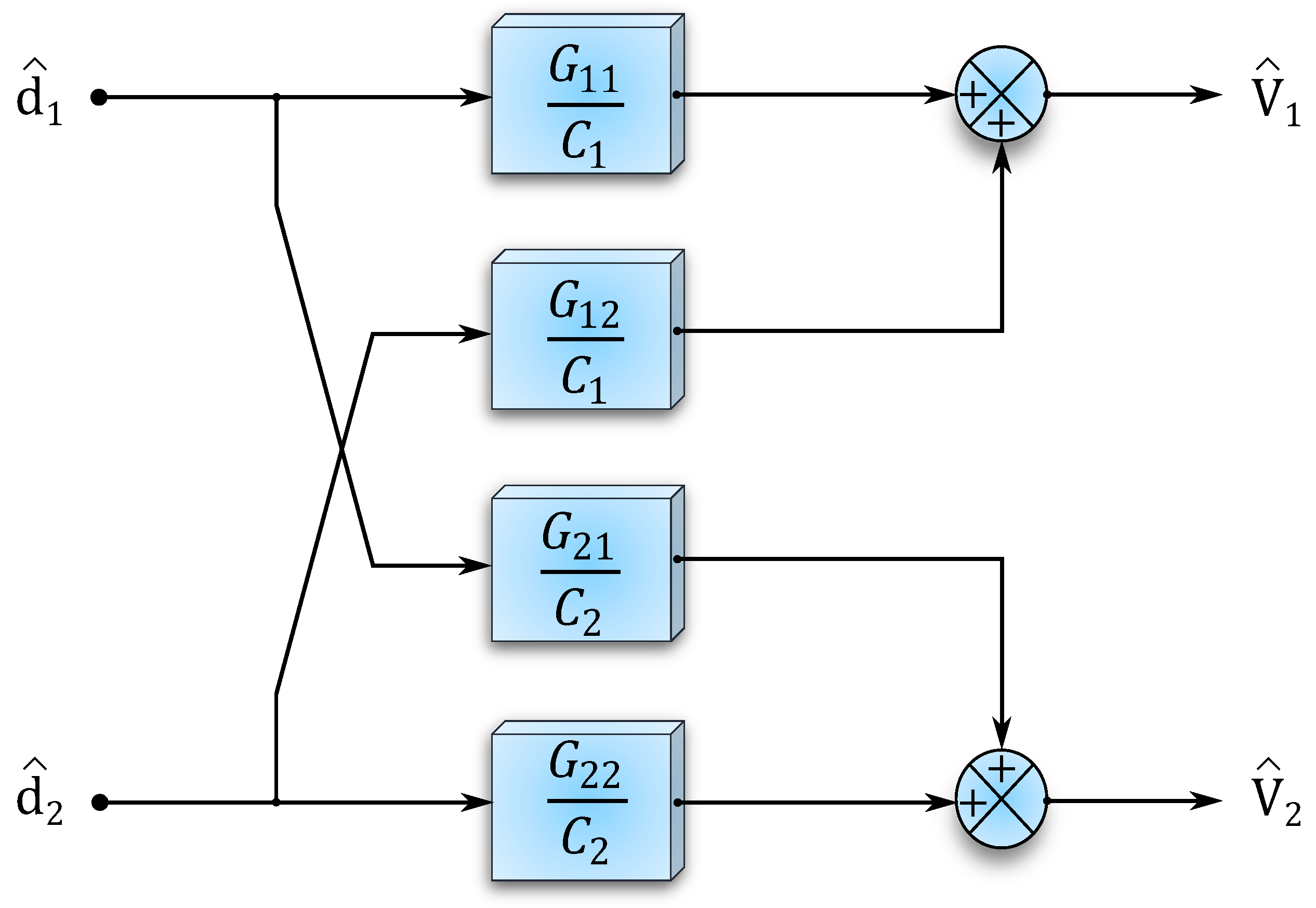
The control block diagram of a TAB converter (taking the 3rd port as an input and two other ports as outputs) is shown in Figure 11, and the control-to-output relation is described as follows:
v ^ 1 v ^ 2 = G 11 C 1 G 12 C 1 G 21 C 2 G 22 C 2 d ^ 1 d ^ 2
where the G 11 , G 22 (diagonal elements of the gain matrix) show the direct effect of the control on the outputs, and G 12 , G 12 (non-diagonal elements of the gain matrix) represent the inner interaction and cross-coupling between the two ports. The expression for the diagonal and the non-diagonal elements of the gain matrix in (10), demonstrates that the effect of cross-coupling terms (non-diagonal elements) is less and has opposite polarity to the direct effect terms (diagonal elements). In other words, an increase in d 1 , directly boosts v 1 , but reduces v 2 with a smaller gain.
The ratio of the non-diagonal element to the direct effect is known as the cross-coupling degree, which for the MAB converter is between 0 and 1 ( 1 < G i j G i i < 0 ). If the G i j G i i 0 the cross-coupling effect will be small, and the control complexity will be less. In steady-state design, by increasing the number of ports (control outputs), the cross-coupling degree becomes close to zero [168]. Figure 12 shows the area plot for the gain matrix of the three, four, five, and six-port MAB converter, which illustrates the intensity of the cross-coupling (non-diagonal elements) for each case per unit (p.u.). Similarly, Figure 13 depicts the % ratio of the non-diagonal to diagonal elements of the gain matrix for numbers of ports from three to twenty. Here it is assumed that there is one input port and the rest are outputs, the line inductances between all ports are equal for all cases, and the phase shift ratios between the input and output ports are identical and equal to 0.1 . According to both figures, the degree of cross-coupling of each port decreases with the increasing number of ports. As an example, for the conditions mentioned, for a three-port MAB converter | G 12 G 11 | 55.5 % while for the ten-port MAB converter, | G 12 G 11 | 13.7 % . Besides the number of ports, as mentioned in the literature, the inductance values and the operating point of the converter (phase shift, power, and voltage of each port) also influence the magnitude of the cross-coupling.
Cross-coupling can complicate the control strategy of the MAB converter since any sudden transient in the load or control input at one of the ports will add a disturbance to the output of the other ports. Hence, decoupling the MIMO control into SISO control systems is desirable to improve the dynamic performance, and reliability of the MAB converter. Researchers have investigated different control-level, or hardware design approaches to reduce, or ideally eliminate the interaction between control loops, which are represented generally in Figure 3.
It is worth mentioning that the urgency for power flow decoupling depends on the application, for example, the work in [58] proposed the MAB converter for DFIG in wind turbines; in this application, rapid transients in the generation or the grid do not usually occur (except under fault conditions). In other applications such as differential power processing in data centers [75], the number of ports can be more than ten, thus, the cross-coupling degree is relatively small compared to a three-port MAB converter (TAB). In this sort of application, a well-designed proportional-integral (PI) controller can regulate the outputs without any significant disturbance, hence, no additional decoupling strategy is required. In [28], the power flow coupling in a TAB converter is intentionally utilized for voltage balancing of the positive, and negative buses in a bipolar DC distribution grid.

4. Control-Level Decoupling

Control-level decoupling approaches are widely explored methods for eliminating or reducing the coupling in MAB converters. These methods do not modify the classic topology of the MAB converter and do not require any auxiliary power components. Several linear control-based decoupling methods have been investigated and studied in control theory, and lately, applied to decouple the control of the MAB converter.

4.1. Conventional Feedforward Decoupling Approaches

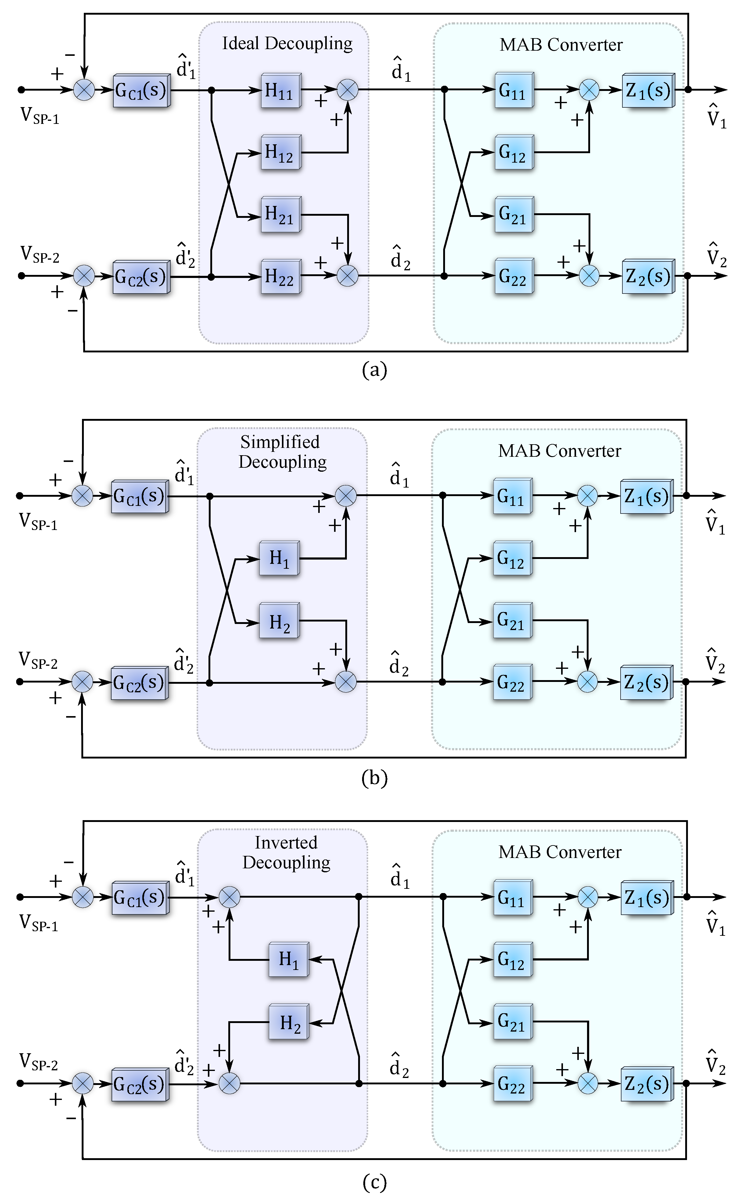
Figure 14 depicts three, linear control-based, feed-forward decoupling approaches. The controller section of each approach consists of two parts; in the first, a PI controller is assigned to each control loop ( G C 1 , G C 2 ), and regulates the control output (in the figure the control output is voltage, but it can be current or power), and the second part is the decoupling strategy ( H 11 , H 12 , H 21 , H 22 , H 1 , H 2 ). Ideal decoupling was the first proposed and is the most often implemented approach for the MAB converter. Using ideal decoupling, the inverse of the steady-state values of the gain matrix can be implemented in feed-forward to ideally eliminate the coupling effect, for which the decoupling terms [165] are:
H = H 11 H 12 H 21 H 22 = G 1 = G 11 G 12 G 21 G 22 1 = 1 G 11 G 22 G 12 G 21 G 22 G 12 G 21 G 11 H 11 = G 11 G 22 G 11 G 12 G 12 G 21 H 12 = G 12 G 22 G 11 G 12 G 12 G 21 H 21 = G 11 G 21 G 11 G 12 G 12 G 21 H 22 = G 12 G 22 G 11 G 12 G 12 G 21
Hence, using ideal decoupling, the overall matrix of the control system G H will be a diagonal matrix with non-diagonal elements equal to zero:
X = G H = X 1 0 0 X 2
However, using ideal decoupling based on constant gains at the operating point has several drawbacks:
  • Ideal decoupling can lead to complex expressions for the decoupling terms and is difficult to realize [169].
  • The conventional decoupling has a centralized control structure, which means the number and complexity of the decoupling terms will increase with the number of ports, especially in applications with multi-directional power flow requirements.
  • Effective performance of the feedforward linear control-based decoupling methods, requires a precise dynamic model of the converter [169].
  • The control-to-output behaviour of the MAB converter with large phase shift values is highly non-linear. In general, linear control-based feedforward decouplers are not capable of dealing with significant non-linearity, and hence their desired performance is limited to the specific operating points in linear regions, and, the maximum power rating is restricted [170].
  • Taking the RHP zero caused by the inductor dynamics into account, can make the decoupling design complicated [15].
  • It can reduce the overall dynamic performance of the MAB converter [101].
Simplified and inverted feed-forward decoupling techniques are studied and explored in control theory, used in industrial MIMO control systems [169], and are proposed for the MAB converter [63], to overcome issues with the complex derivation of decoupling terms for ideal decoupling. The two remaining decoupling blocks ( H 1 , H 2 ) in the simplified and inverted feed-forward decoupling approaches can be found using the following expressions:
H 1 = G 12 G 11 H 2 = G 21 G 22

4.2. Other Linear Control Approaches for Decoupling

Although using simplified and inverted decoupling can reduce the computation of the decoupling terms, problems still exist with non-optimal decoupling at other operating points. To solve this problem, the works in [34,76,171] store pre-calculated values of the decoupling matrix for all operating ranges. Although it was termed an online decoupling method, it requires a look-up table and is a gain scheduling-based approach. With step changes in the system (load, or set point), a step change in the operating point occurs as well, and the gain scheduling may not achieve the desired decoupling performance. The proposed method in [111] neglects pre-calculation of the decoupling terms and their dependency on the operating point. Consequently, based on the reported experimental tests, this method is not always totally effective in terms of decoupling and robustness to disturbances.
Other research has proposed multi-loop controllers instead of a single-loop PI controller for each port. The work in [162] proposes a TAB converter (with half bridges) for HESS applications. In addition to simplified decoupling, two inner current control loops, and one outer voltage loop with a current-sharing strategy are implemented. The experimental test demonstrates a satisfactory decoupling performance under load step changes. The research presented in [166], uses outer voltage feedback loops to maintain DC voltages, and then their output is adjusted with inner current feedback loops and a current reference to control the current at the ports, in addition, the inverse of the gain matrix is implemented. The work in [172] combined TAB converters with H-bridge inverters for a railway power system integrated with RES. In addition to ideal decoupling, five different multi-loop control stages are proposed and implemented to fully control the voltages, currents, and powers of all ports. Although this method provides adequate flexibility and good transient response, it is extremely sophisticated. In order to have more control variables participating in the system dynamics, the work in [63] uses a simplified decoupler to decouple the outer phase shift(s) to output voltage control, and a third power control loop is assigned to control the power transfer between two output ports (the power flow that causes cross-coupling) by adjusting one of the inner phase shifts.
The work in [164] uses conventional decoupling and the concept of dq-frame control based on the FCA model for power flow decoupling in a TAB converter. Low-pass filters are used to extract the fundamental components of the transformer currents, which can add delay to the control. The main contribution of [164] is the compensation for the delay caused by low-pass filters in the current measurements. However, since this method only considers the fundamental components of the measured parameters, it misses the power flow information of higher-order components.
Using well-tuned multi-control loops without separate conventional decouplers can provide a moderate dynamic response. The work in [15] uses asymmetrical duty cycle control plus phase shift in a TAB converter for optimization purposes. The paper considered the dynamics of the linking inductance and illustrated that under full load conditions, the RHP zero can appear at 1 kHz. Since the implementation of conventional decoupling became impractical, the work adopted different bandwidths for the controller of each port, and hence the high bandwidth loop can determine the direction of the power flow during the transient period. As a result, the control loops can be regulated independently and do not interact with each other. Similarly, the work in [95] selected different bandwidths for two power control loops to mitigate the interaction between them. The same concept (different bandwidths for control loops) was implemented for a QAB converter [51]. The combination of both, gain inverse matrix and different bandwidth for control loops has also been proposed in [17].
The research presented in [58] proposes a QAB converter for the DFIG application, where one of the ports is allocated for the rotor side, and the three other DC ports are connected to the AC grid through additional cascaded H-bridge inverters. There are two different current sensorless controllers proposed, for the rotor side, a dual loop PI resonant voltage controller is implemented to strictly regulate the voltage and reduce the sensitivity to load disturbances. The second controller contains the dual loop voltage balance controller and an internal decoupling technique to balance the voltage of three grid-side ports. The combination of the two proposed control architectures can provide more robustness compared to conventional decoupling methods. The disturbance rejection, and control decoupling capability of the proposed controllers under significant load variation, and step changes in the wind speed are validated, and compared with simple PI, and PI resonant controllers. The work in [94], proposes two individual control architectures for controlling the same converter as reported in [58]. The first controller contains several disturbance attenuation loops, which can effectively reduce the disturbance overshoot in all ports. The second controller was allocated for the elimination of the mismatch in the linking inductance parameters, and to mitigate the power mismatch routing. Both works [58,94] can decouple power flow in a MAB converter, without implementing conventional ideal or simplified decouplers; however, the design effort of the proposed multiloop controllers is relatively high.
Figure 15a illustrates the control block diagram of the proposed control structure in [94] that contains an outer voltage control loop and multiple load disturbance attenuation loops, where the number of the inner loops depends on the load disturbance attenuation level and its Nyquist bandwidth limitation. C v represents the controller of the outer loop, C p 1 , C p 2 , , C p n are the inner loop controllers, P c 1 , P c 2 , , P c n are the open loop plant model, G o is the original plant model, and the load disturbance is represented by V o ( d i s ) . It is demonstrated that considering C p 1 = C p 2 = = C p n and P c 1 = P c 2 = = P c n = G o leads to totally independent operation of the control loops, and the outer voltage control loop can track the reference voltage and regulate the control output without any interaction with inner loops.
Figure 15b depicts the combination of two proposed dual-loop PIR voltage controllers and the dual-loop individual voltage balance controllers in [58]. The proposed controllers provide excellent performance in terms of voltage ripple reduction and are robust to the disturbance caused by load variation. G c o n t represents the PIR controller, in which the PI controller is allocated to reference voltage tracking, and the resonant part of the controller limits the second-order voltage ripple, to achieve an effective disturbance rejection performance. G o v is the virtual plant of the dual loop controller and the gain of k 1 is designed. The PIR controller is expressed by the following term, in which P o , I o shows the gains of the PI controller, and k r is the resonant gain.
G c o n t = P o + I o s + 2 k r s s 2 + ω r 2
The virtual plant model should be G o v = G o and must accurately be determined in order to eliminate the interaction between disturbance rejection loops, and the outer voltage regulator loop, and strictly reject the disturbance. Hence, accurate modelling of the actual planet model G o is required. If this condition is satisfied, the effectiveness of the disturbance rejection controller is determined by the controller parameters G c o n t and k 1 . Finally, decoupled dual loop individual voltage balance controllers are designed to individually balance the grid-side ports and improve the stability margin.
The work in [59] proposes a TAB converter for the integration of battery storage with DFIG, which operates as a unified power quality controller. Similarly, PI controllers with no decoupling strategy are proposed in [14]. The work in [173] proposed a TAB converter for the integration of hydrogen-based fuel cells with a traction power system, where single-loop PI controllers are implemented to maintain the currents at each port. The research presented in [68], proposes a TAB converter for the integration of PV modules with the battery storage system in a nanogrid. A linear simple PI controller is implemented to regulate the DC bus voltage and a maximum power point tracking algorithm is developed for power sharing between three ports, then a current control loop is assigned to the load side port. The combination of these various parts of the control structure can behave as a moderate decoupler when a disturbance happens. Although these single-loop control strategies have a simpler structure, they lead to reduced dynamic performance under step changes in the load or generation.
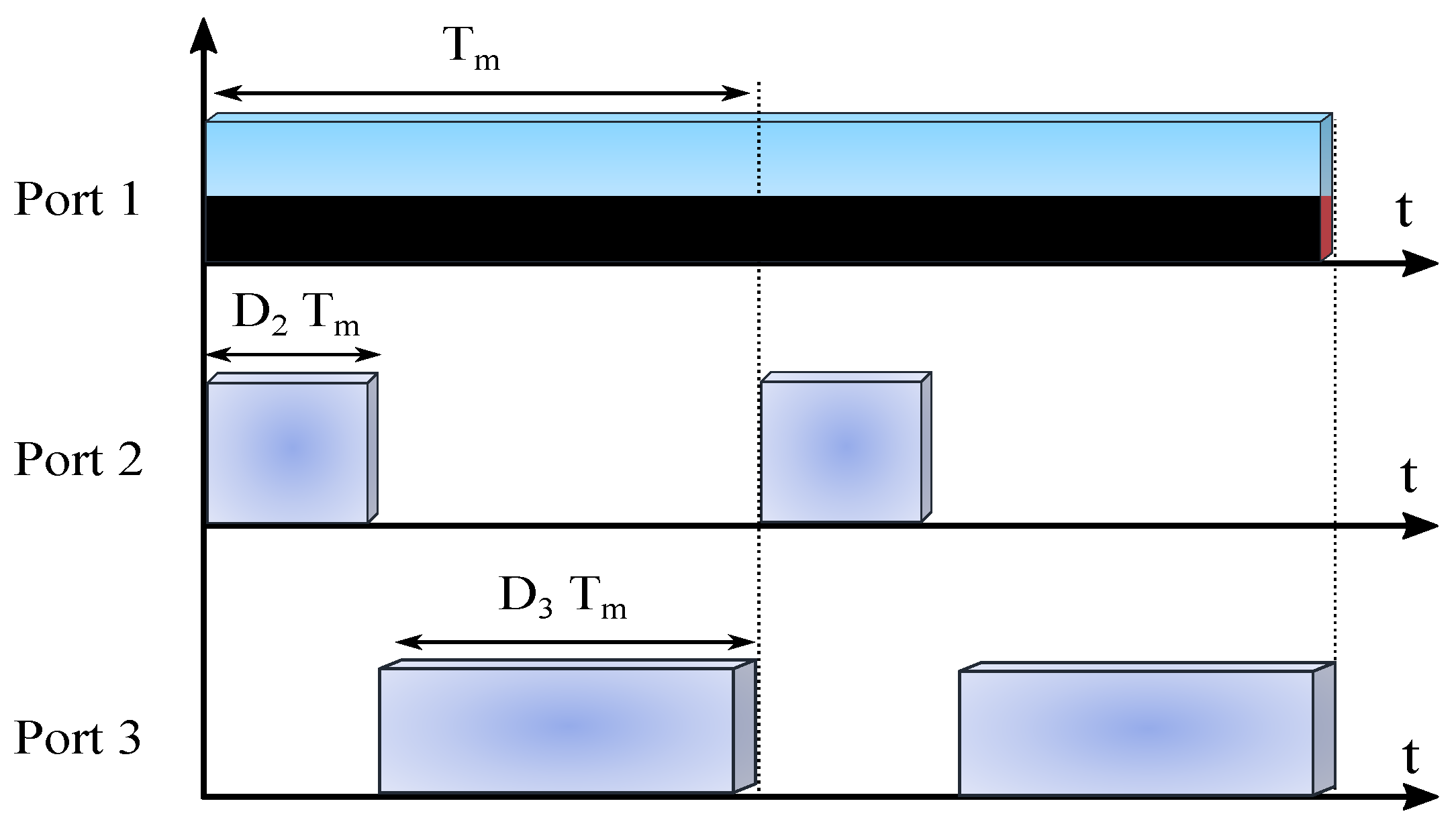
Time-sharing is an interesting modulation approach for multi-port converters because it can provide independent power flow control between two ports of the multi-port converter, and a single PI controller for each port can independently regulate the power flow. Using this approach, only two ports are operating at each time instant. In other words, considering an input port and two output ports in a three-port converter, the operation period of the input port is divided among the two output ports. Figure 16 shows the time-sharing control of a three-port converter, where T m represents the shared period (the input port), and D 2 , D 3 are the time-sharing ratios of the two output ports, considering T m = 1 p.u, one has D 2 + D 3 1 , and there is no overlap between the operation period of the two output ports.
The research presented in [83], proposed a QAB converter for DC power management in smart homes, in which a hybrid time-sharing, phase shift approach is implemented to have independent power flow control. A similar idea is implemented in [93] to control a 12-port MAB converter, which is proposed as a multi-cell reconfigurable energy router. Although the time-sharing method has straightforward implementation and can achieve a fully decoupled control of power flow, it increases the output voltage ripple and larger output capacitors are required, besides, the device stress under time-sharing is higher [83]. In addition, the power density drops with the increasing number of ports. As was discussed in the literature, and demonstrated in Figure 12 and Figure 13, the cross-coupling effect in a MAB converter reduces with the number of ports. For the 12-port converter represented in [93], the interaction between control loops is negligible, hence, using phase shift modulation with PI controllers could also provide an adequate dynamic response. The research presented in [75,170] illustrated that individual controllers are sufficient for large-scale MAB converters, and validated it experimentally using two 10-port MAB converters. Table 2 compares the different linear-control-based approaches that have been proposed for the MAB converter.

4.3. Nonlinear Control Approaches

The small signal model derivation demonstrated the nonlinear behavior of the control to the output transfer function. Hence, nonlinear control techniques are interesting for controlling MAB converters and can extend the operating region. The work in [35] solves the nonlinear power flow equations of a 12-port MAB converter using a simplified Newton iteration method. By combining the solutions obtained and the inverse of the gain matrix, the power flow of the MAB converter can be decoupled over a wide operating range. However, as was mentioned before, for large-scale MAB converters, the cross-coupling is much less, and the decoupling strategy is not essential.
The research presented in [22], demonstrated that the local sub-module (H-bridge) optimal points for power flow decoupling are the same as the global optimum solutions. Hence, local controllers for each sub-module can decouple the power control of each port. An MPC-based strategy is proposed for the TAB converter in [22], where the first part of the controller aims to find the optimum future state of the DC current in the next two steps (two-horizon) using a binary search and feedback from the DC voltages, then the second part of the controller uses optimal predicted values for the DC current and decouples the power flow through an open loop algorithm based on Newton’s iteration method. Theoretical analysis and experimental tests demonstrated excellent transient response compared to the conventional linear control approach, possibly at the expense of slightly higher steady-state error.
The research presented in [43] aimed to predict the AC midpoint current using linear searching. The phase shifts are considered to be close to zero, thus, a linear relationship between the power flow (midpoint currents as well) and phase shift ratios is achieved. Then one iteration of Newton’s method is performed to obtain the desired value for the phase shift. The work in [78] applies MPC based on the SPS modulation, to predict the optimal phase shift for future states. Simulation results show a good dynamic response under load step changes, but the steady-state error is higher than the PI controller approach, and no experimental validation tests are provided. Only SPS modulation is considered for controlling the power flow in all described MPC approaches; by taking inner phase shifts into account, the calculation of the Jacobian matrix in Newton’s method can be computationally intensive, and other simpler iterative methods may not give adequate precision.
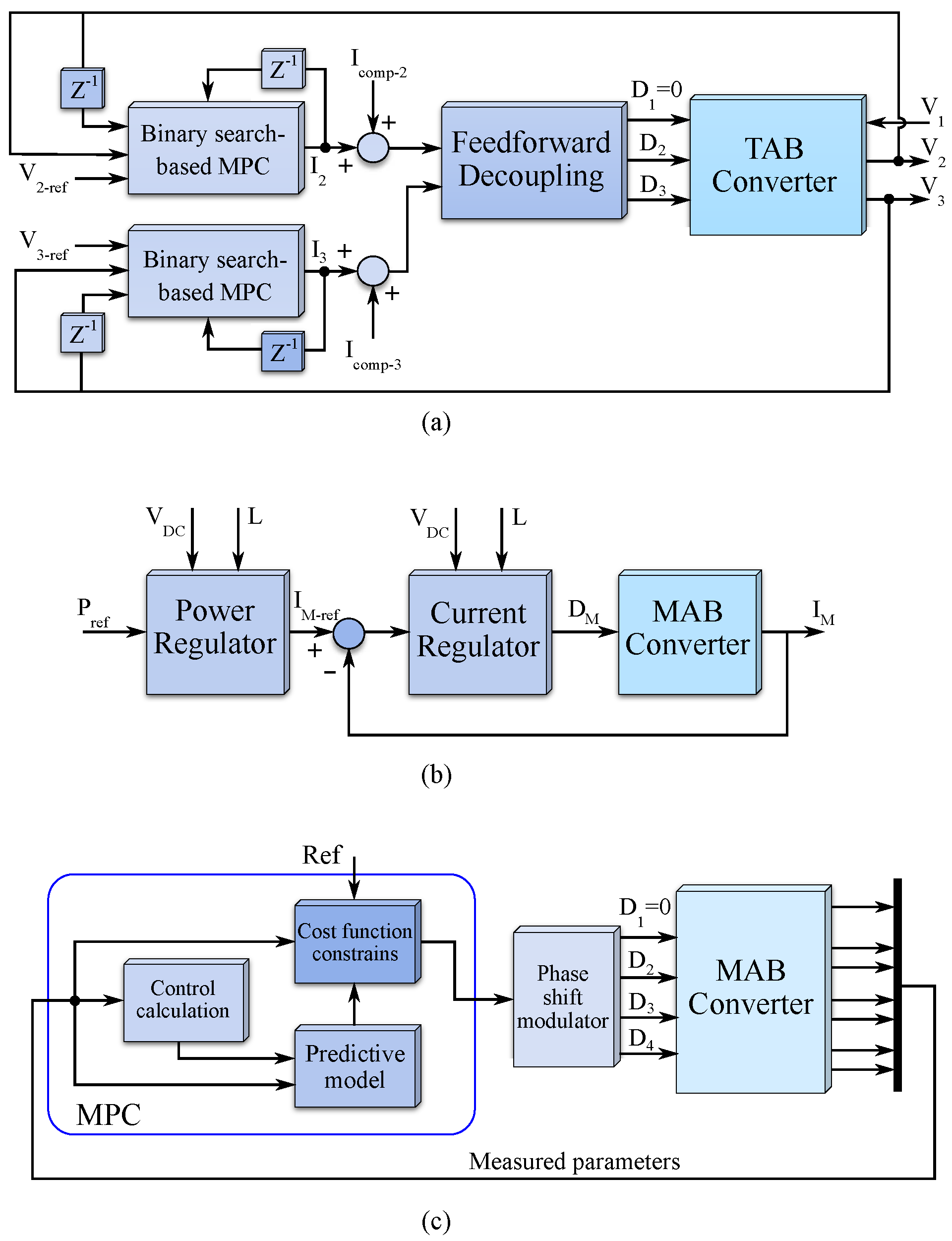
To enhance the effectiveness of feedforward decouplers at all operating points, other works proposed nonlinear control-based, and black-box approaches. The work in [177], implements the feedforward controller using a model predictive controller (MPC). The discrete first-order delay time state-space model is established, to meet the requirements of the proposed control approach. In addition, a non-linear fast-track algorithm is implemented, hence, the proposed control has a robust and satisfactory dynamic response, compared to the conventional ideal, simplified, and inverted decoupling approaches. The block control diagram of the proposed MPC-based approaches is shown in Figure 17.
In one paper [21], a multi-layer neural network is trained with 100,000 datasets, provided by simulation of a QAB converter to observe nonlinear control-to-output relation. Three outer phase shifts are selected as inputs, and four voltages are the outputs. Finally, the NN-based model obtained is combined with the linearized analytically derived model. In fact, NN results are used for accuracy compensation of the linear model and can improve the accuracy of the linear model by 60%. However, the range for outer phase shifts considered is [ 0.3 , 0.3 ] , and the remainder of the possible range (which leads to more nonlinear characteristics) is not taken into account. Another NN-based method is presented in [99], which employs data sets to train a neural network for RMS current optimization and to determine the optimal inner phase shifts. Outer phase shifts are controlled by PI controllers and decoupled with gain matrix inversion. Since the inner phase shifts influence the dynamic performance of the converter and are determined by a pre-trained NN, the transient response of the converter to step changes in the load is improved. In one study [91], a feedforward machine learning-based algorithm is trained to capture the nonlinear behaviour of a 6-port MAB converter. Although the motivation of the work is to find corresponding optimal phase shifts at each operating point, the proposed approach can achieve good power flow decoupling performance.
To push control robustness further, some researchers have proposed disturbance observer-based nonlinear control approaches and algorithms, such as active disturbance rejection control (ADRC) [84], sliding mode control (SMC) [86], and the super-twisting algorithm (STA) [60]. Classic linear control techniques are not capable of totally attenuating the impact of uncertainties caused by external environments, perturbation in parameters, and unmodeled dynamics of the system [178]. The disturbance observer-based control techniques applied to the MAB converter, use an extended state observer (ESO) for lumped disturbance estimation. Since the effect of cross-coupling is treated as a disturbance, it can be observed by ESO and rejected using appropriate control strategies.
The research presented in [84] proposes a linear ESO-based linear ADRC to effectively decouple the cross-coupling in a QAB converter. Besides providing more robustness and reliability, the proposed method does not require a dynamic model for the converter and only requires information about the state of the control system (which is basically the number of energy storage elements). It has a decentralized control structure, hence, unlike classic control methods, the complexity is independent of the number of ports. The first part of the control system is a linear Luenberger observer which includes the estimation parameter for the system states. After a disturbance and corresponding fast disturbance observation, a simple proportional derivative (PD) controller rejects the observed disturbance.
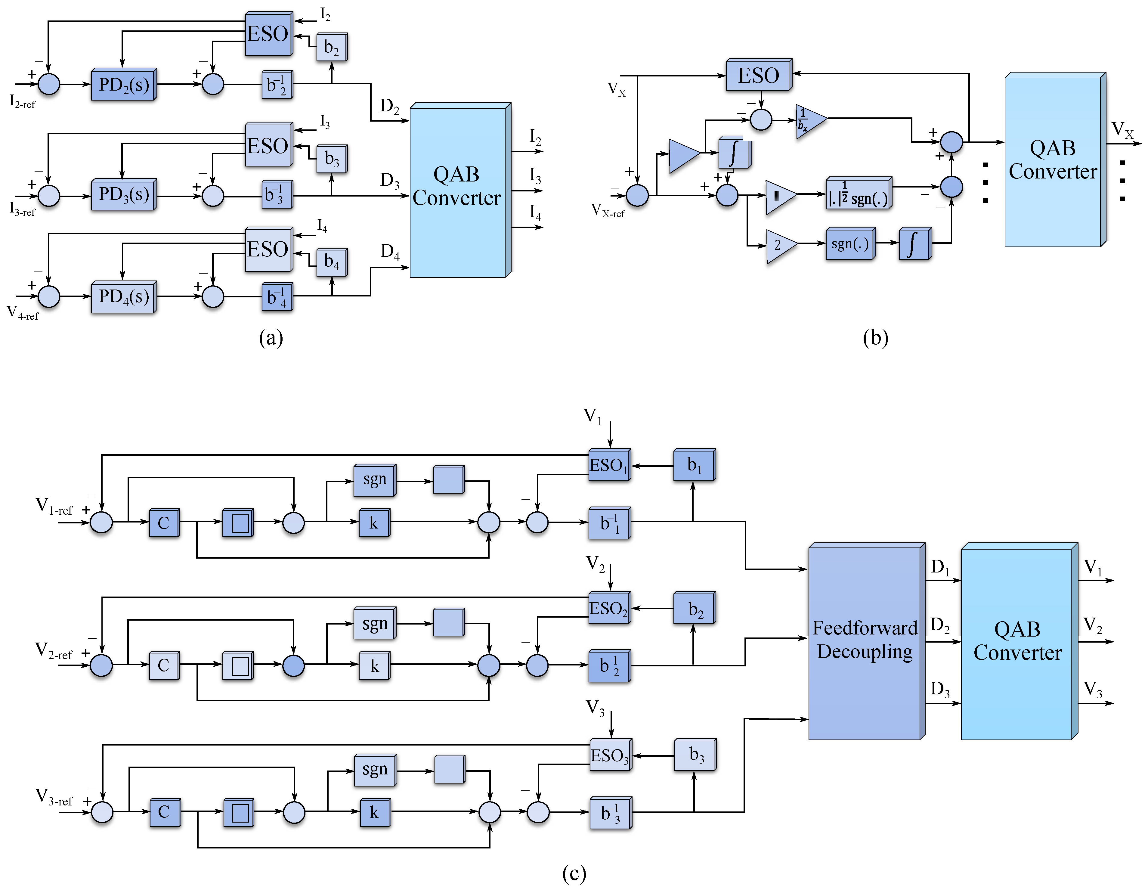
The research work presented in [86] aimed to fully eliminate the cross-coupling in a QAB converter using an ESO-based SMC with a conventional gain inverse matrix. The conventional decoupler performs most of the cross-coupling rejection, and the remaining interaction between control loops is eliminated by the SMC. The combination of the conventional and SMC decoupling approaches enhances the robustness of the control system, and regardless of the operating point, it can fully eliminate the disturbance caused by inherent interaction between loops. In fact, the ESO is not an essential part of SMC control; however, it can solve the chattering problem in SMC and improve its performance. Among the different control approaches reviewed here, Ref. [86] has presented the best decoupling performance. A super-twisting algorithm (STA) control based on an ESO is proposed and implemented for power flow decoupling in a QAB converter and demonstrates excellent transient response under step load changes. The control block diagrams of these three ESO-aided control approaches proposed for the MAB converter are depicted in Figure 18.
Adaptive control-based approaches have also been proposed for MAB converters, and are mainly used for power flow management. The work in [100] presents a decentralized adaptive control, which adapts the switching frequency and the phase shift of each bridge of a TAB converter to control the power, and an extension of work is presented in [179]. The work in [13] proposes an adaptive energy management strategy for a TAB-based HESS which adaptively manages total power distribution among different types of energy storage devices.However, all mentioned adaptive control-based approaches were concentrated on power flow management and did not consider any robust decoupling mechanism for step changes in the system, hence, low transient responses under step load changes are demonstrated.
The research carried out in [85] proposes an adaptive “step perturb and observe algorithm” for tracking the minimum transformer RMS current to minimize conduction losses by adjusting inner phase shifts and regulating the active power in a QAB converter. The proposed strategy does not require accurate modelling of the converter, and it is LUT-free. The outer phase shifts are controlled by PI controllers and decoupled using a conventional feedforward decoupler. There are some other nonlinear control-based approaches proposed to decouple the power flow in MAB converters, such as flatness control [98,180], and natural switching surface control [35], these are not discussed further here.
Table 3 compares different control-level papers for the MAB converter. The papers are compared in terms of the type of control approach, decoupling effectiveness, complexity, number of ports, implemented modulation technique, steady-state modelling approach (TDA, FCA, GHA, and model-free), and experimental and setup specification.

5. Hardware-Level Decoupling

The implementation of control-level decoupling techniques has a trade-off between accuracy and complexity, where conventional methods are less effective and novel robust control approaches are more difficult to design in general. To address this problem, topology-level decoupling approaches have been investigated, with the aim to achieve excellent decoupling and simple control design at the same time. As discussed in the literature, the linking inductance plays a crucial role in the power flow of the MAB converter, in both steady-state and transient conditions. The physical origin of cross-coupling is when part of the linking inductance is “shared”, as shown in (Figure 4), for example, due to the leakage inductances in a multi-winding transformer. Therefore, topology-level approaches generally aim to separate a MAB converter into several DAB converters by using additional series-connected inductances or manipulating the magnetic coupling between windings.

5.1. Modified Inductance Type MAB

Considering the star-type ECM of a TAB converter with one input (e.g., port 1) and two output ports (e.g., ports 2 , 3 ), the transferred power to each output port is affected by its winding leakage ( L 2 or L 3 ) inductance, and the leakage inductance of the input port winding ( L 1 ). Since the current flowing through L 1 is shared between the outputs, it impacts the delivered power to them. Clearly, by arranging for example L 1 L 2 , L 3 , the influence of L 1 on the transferred power can be reduced and in this case, the power flow to each consumer port can be controlled as if there were separate DAB converters. However, tuning the leakage inductances in multi-winding transformers is challenging and high values for leakage inductance are difficult to achieve.Consequently, external auxiliary inductors connected in series with some of the windings have been used by most researchers to achieve the desired effect.
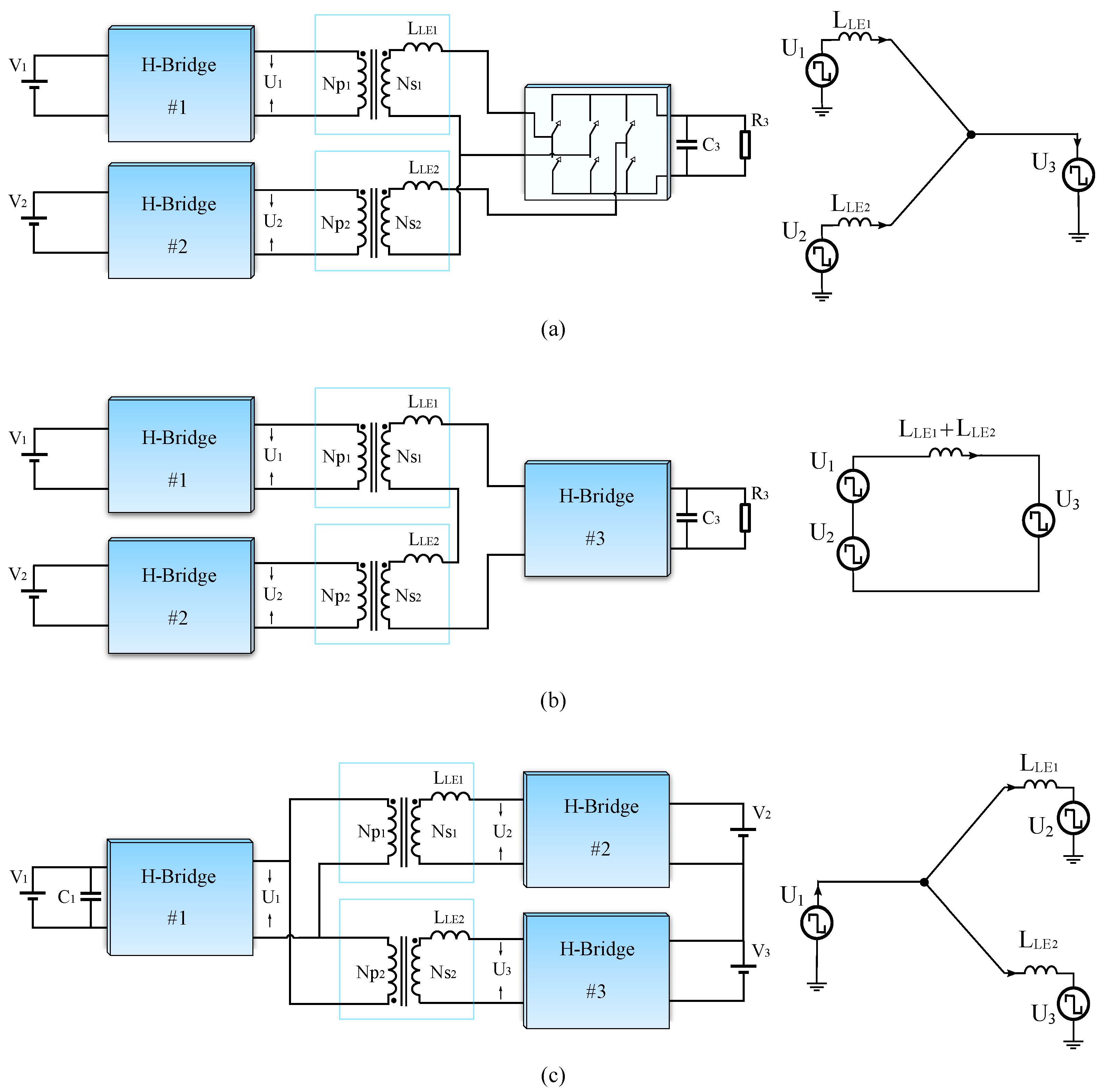
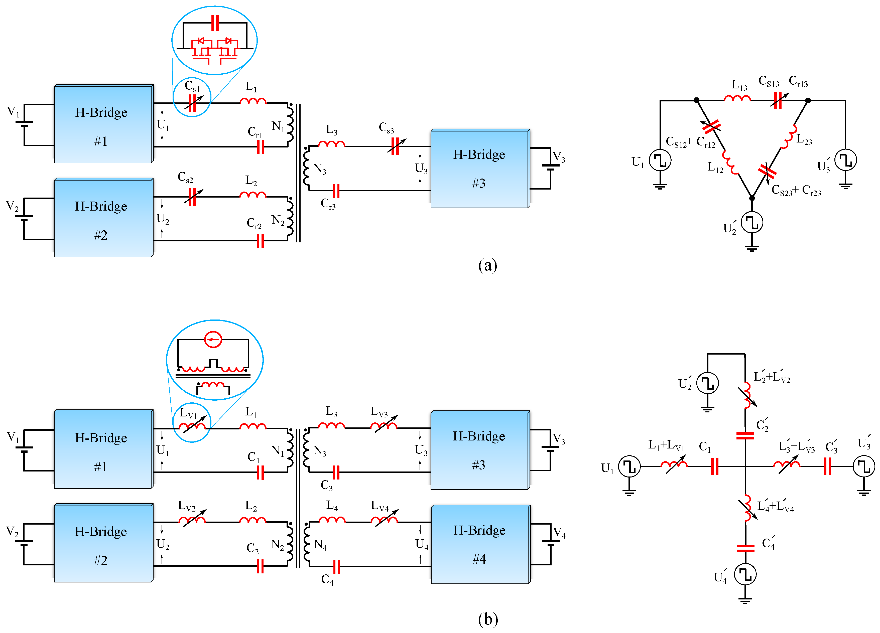
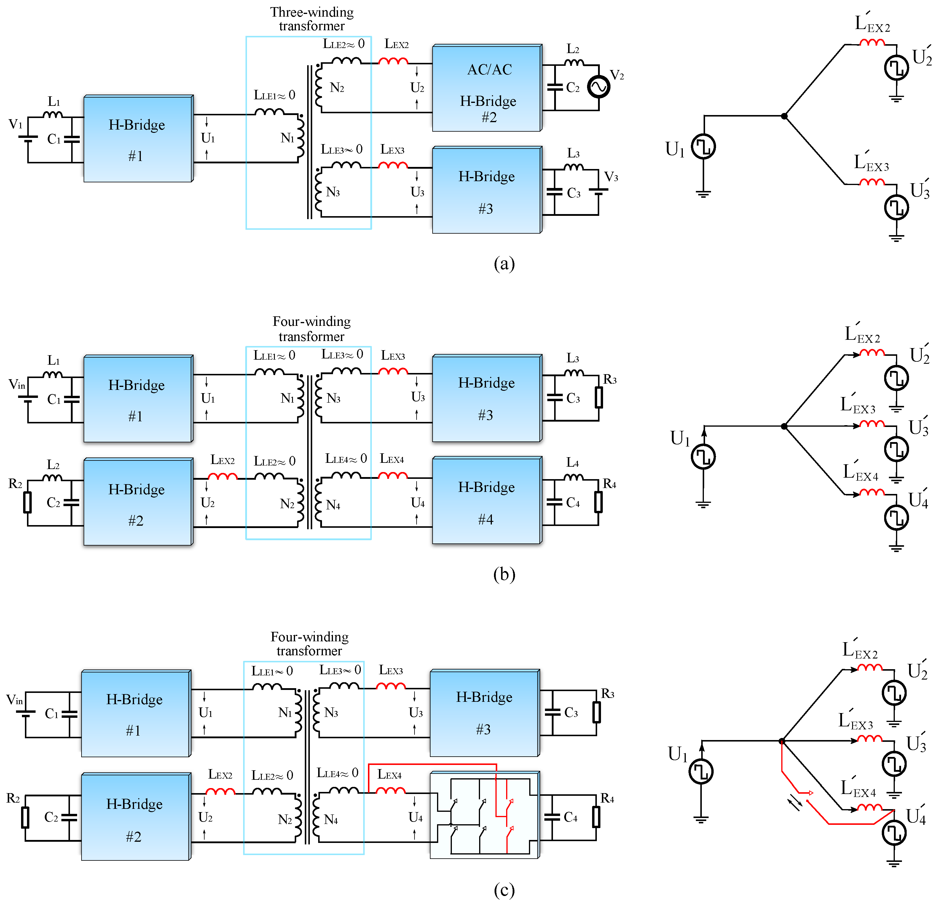
The idea of modified leakage inductance-based decoupling was first mentioned in [78], then the work in [106] used the concept of modifying inductances in a three-port converter, which consists of two conventional H-bridges and an AC to AC H-bridge with 4-quadrant switches. The inherent leakage inductances are very small, and external inductors are connected in series with two of the windings to create a larger equivalent inductance. Hence, the interaction and cross-coupling between them are reduced at the topology level. A similar idea was adapted to a QAB converter in [87], where external inductors are connected in series with three of the output port windings so that the common inductance is limited to the small leakage inductance of the input port winding which becomes negligible. The ports with added inductance can have independent power control since the first port essentially becomes an “ideal” voltage source. Although inductance modification greatly simplifies the control design of the MAB converter, the direction of power flow is restricted, since the input and output ports are predefined in the converter design stage by allocating the additional inductors. In other words, in a QAB converter with one input and three output ports (with added inductance), for example, it is not possible to re-allocate one of the output ports as input since the added inductance would become “shared” and there would be very significant cross-coupling between converter’s ports. In addition to the limited power flow direction, the proposed hardware-level solution increases the transformer losses [107]. Figure 19 depicts these different modified inductance approaches and their ECM.
To address the power flow direction limitations, the research presented in [88] proposed a new topology for the QAB converter. In the proposed topology, an extra arm with two high and low-side active switches exists at the bidirectional port. This additional arm can bypass the external inductor to create an input port or leave it connected to create an output port maintaining decoupled power flow in both scenarios. However, having two more active switches in the bidirectional port(s) increases the overall cost of the MAB converter. Additionally, if the external inductor is bypassed, and two ports are injecting power, the linking inductance between them in the Δ -type ECM can be extremely low (depending on the ratio of the leakage inductance to the external inductor), which can cause a high inrush current. Thus, selecting a satisfactory value for the external inductor is important. Additionally, if the two input voltages are unequal, the small line inductance between two input ports in the Δ -type ECM causes high circulating power, which increases the conduction losses [181]. To address this problem, it is important to have equal voltages connected to input ports or to apply advanced multi-phase shift modulation to reduce the circulating power.
The research presented in [182] aimed to achieve the desired value for the linking inductances without using additional series inductors. A genetic algorithm approach was used to optimize the leakage inductances based on the position of the windings, to have a lower leakage inductance for the input winding and relatively higher leakage inductances for the output windings. Several different transformer structures were investigated in an attempt to obtain the desired leakage performance in terms of absolute values and ratios.

5.2. Separate Multiple Transformers

Other Hardware-level methods are based on replacing the HF multi-winding transformer with several conventional two-winding HF transformers. Implementation of individual two-winding transformers in a MAB converter can provide several merits such as:
  • Two winding transformers are much easier to design, manufacture, and optimize [183]. Moreover, desired leakage inductances are easier to achieve.
  • Since two windings can be wound on different arms of the magnetic core, two-winding transformers can provide better galvanic isolation for high-voltage applications, especially when the voltage difference between two connected ports is considerable.
  • The magnetic coupling between two transformers is neglected, hence, the cross-coupling effect can be reduced or fully eliminated (depending on the connection of the transformers).
  • In a multi-winding transformer-based MAB converter with two inputs, a small deviation or disturbance in their voltages or the phase shift between them can cause circulating power and higher conduction losses, while an implementation with multiple two-winding transformers can overcome this problem.
  • In the conventional MAB converter, with unequal phase shifts at the input ports, two voltages oppose each other (for part of the period), and this leads to a reduction in the slope of the sum of the produced magnetic flux. As a consequence of the lower rate of change in magnetic flux, the back electromagnetic force (EMF) will be reduced which causes high inrush currents from input ports. In the worst-case scenario when V i = n i j V j , a magnetic short circuit occurs [109]. Using two-winding transformers can address the magnetic short-circuit drawback of conventional MAB converters.
  • In [41], it was suggested that an MWHFT in a MAB converter can have problems with saturation which are exacerbated as the number of ports (windings) increases - although the mechanism for this effect was not fully explained or discussed.
  • Two-winding transformers can provide better heat dissipation than multi-winding transformers [184].
  • Using two-winding transformers, the scalability of the converter is greater, since the implementation of a multi-winding transformer does not do not allow retrospective addition of another port (isolated active bridge) [104].
In fact, the main motivation for splitting the transformer in [109] was to mitigate the power circulation and magnetic short circuit when there are two input ports. The proposed three-port MAB converter with two split two winding transformers is shown in (Figure 20a). Each of the transformer primary windings is fed from a voltage source through an H-bridge, while the secondary windings are connected in series to supply the load through a 3-arm active bridge. A similar concept is presented in [108], in which two half bridges are implemented for the input side ports. However, adding two more switches increases the overall cost and losses in the system. In addition, unequal power sharing between two inputs with asymmetrical (different) phase shifts, lower power density, and uneven component current stress are other drawbacks of the proposed approach. Although the transformers are magnetically decoupled, the series connection of the winding makes it electrically coupled. However, the coupling effect is reduced compared to a three-winding transformer-based MAB converter, and the PI controller can overcome the remaining interaction. However, the power flow can be decoupled in the specific case when the two AC voltages produced by input bridges are synchronised.
The proposed three-port topology presented in [37] (Figure 20b), removed the additional added arm to one of the H-bridges in [109], and power flow decoupling is extended to all operating conditions. In addition, inherent open-loop power balancing is provided by considering a phase delay between the AC square wave voltages of two input ports. The work presented in [149] mentioned power flow decoupling of the TAB converter by splitting the three winding transformers into two winding transformers. In order to absolutely eliminate the interaction, two windings of the transformers are connected in parallel and the topology is magnetically and electrically decoupled. However, the current-sharing problem still remains.
The research presented in [30] proposes a TAB converter, with split transformers, for a bipolar DC distribution system to isolate the DC system from the AC grid and provide voltage balancing of the bipolar DC bus in a single stage. The topology consists of a full H-bridge connected to the input source and two series-connected half-bridges that provide the two voltage levels required for the bipolar DC buses (Figure 20c). Since the two transformers are connected in parallel, the power flow is totally decoupled, and there is no interaction during the voltage balancing. A similar topology, that consists of three full H-bridges, is proposed in [31] to supply loads in a bipolar DC distribution grid. The work in [80] combines a series-connected triple transformer-based MAB resonant converter with three H-bridge inverters to create a DC to three-phase structure and HF three-phase decoupling is implemented to reduce interaction.
To interface a medium voltage (MV) bipolar DC system with a low voltage (LV) bipolar DC distribution system, the work in [33] proposed a converter with a new architecture based on two series-connected modular multilevel converters (MMCs) for the MV side, and four interleaved full H-bridge converters for the LV side to provide two required voltage levels and high current capability. Four two-winding transformers are connected two by two and link the MV and LV side converters together. The series connection of transformers can reduce the cross-coupling, and hence a good dynamic performance is achievable with only PI controllers. A similar topology for the same application is proposed in [185].
Decoupled power flow in multi-transformer MAB converters depends on the architecture and connection of the transformers, and it may not be able to eliminate the interaction between ports. In parallel connection of transformers, there is no cross-coupling since there is no magnetic or electrical coupling between them. In a series connection of transformer windings, the magnetic coupling is neglected but since the current flowing through windings is the same because of the series connection, an interaction between ports appears; however, it is weaker than cross-coupling in a MAB converter with a multi-winding transformer. If more transformers are added to the system to increase the modularity of the converter, a strong interaction between ports can appear again.
The topology of the Modular multi-active bridge (MMAB) converter is proposed in [149] to increase scalability, modularity, and the freedom to have different characteristics for the connected port loads/sources. In the proposed topology for MMAB, each port (module) consists of an H-bridge and a transformer, hence, different multi-port architectures will be available by combining each module. In fact, MMAB has both characteristics and features of DAB and MAB converters. The connection of modules can create the same star or Δ -type ECM of the MAB converter with individual two-winding transformers, and create cross-coupling. Control-level decoupling approaches can be applied to attenuate the interactions [148]. An iterative algorithm is proposed in [147] and applied to solve the nonlinear control equations and obtain the desired values of phase shifts (control inputs) to have independent power flow control. In one study [150], a dq-frame representation of the active power transfers is demonstrated, and the power flow decoupling term is derived to be implemented using feedforward in the control system.

5.3. Resonant-Type Decoupling Approaches

Implementation of a series resonant circuit in a MAB converter was proposed in [186] for the first time, to improve the switching losses, where two resonant tanks are included in two ports of the TAB converter. A QAB converter with four LCL resonant tanks is proposed in [187]. Other papers used different resonant circuits for the MAB converter; however, none of them discussed the cross-coupling issue or decoupled power flow using a resonant-type topology-level decoupling approach [131,132,187]. Implementation of resonant circuits can provide other advantages, using a capacitor connected in series with the transformer windings can modify the equivalent impedance, and if the resonant frequency is selected to be equal to the switching frequency, the effect of leakage inductance on power transfer is eliminated. The port with f r = f s can be considered to be an input port, and other ports with f r < f s will achieve decoupled power flow control and behave as output ports [102] (Figure 21a).
The research presented in [188] investigated resonant-type decoupling for the first time (Figure 21b). The proposed topology is a TAB converter with a multi-resonant circuit, where several passive elements are implemented to create several resonance frequencies. Then based on the established small signal model, dependency of the cross-coupling degree ( G i j G i i ) to the resonant tanks parameters and the ratio of switching frequency to the resonant frequencies are analyzed. Suitable values for the resonant elements and frequencies are selected to reduce the interaction and cross-coupling degree. Research presented in [71] proposed a TAB converter, which demonstrates decoupled power flow, based on two full H-bridges and a resonant half-bridge for integration of a storage system with PV panels.
In [103], a TAB converter with two resonant half bridges and one full H-bridge is proposed. In [105], a TAB converter with two resonant full H-bridges and one normal full H-bridge is proposed. Each resonant tank includes a resonant capacitor and inductor, and an auxiliary inductor connected in parallel, which helps to maintain ZVS with bidirectional power flow. The ”first harmonic synchronized” approach is implemented and it is demonstrated that the voltage conversion ratio is independent of the transferred power and only determined by the duty cycle. Hence, bidirectional decoupled power flow can be achieved using this method. Detailed dynamic behaviour of the resonant QAB converter is investigated in [46], and a power ripple decoupling based on two proportional resonant (PR) controllers is designed to enhance decoupling behaviour. Power flow decoupling in a current-fed TAB converter is proposed in [8]; however, it only discusses the closed-loop characteristics of the proposed converter. The small signal modelling, dynamic behaviour, and closed-loop controller design of a current-fed resonant TAB are studied in [101].
Resonant circuits can be used to provide decoupled power flow at the circuit level without any control complexity; however, the effectiveness of the decoupling, strongly depends on resonant circuit parameters. Due to manufacturing tolerance and standard values, finding passive components with appropriate values and tolerances is challenging. To address these drawbacks, some researchers have proposed the implementation of variable capacitors and inductors to achieve “precise” values based on resonant circuit design [6,12].
A resonant TAB converter with variable capacitance is proposed in [6] (Figure 22a) that can overcome the mismatch in resonant circuit parameters.Each resonant circuit in the proposed topology consists of a switch-controlled capacitor, which is a 4-quadrant active switch in parallel with one capacitor and series-connected with another capacitor. The equivalent capacitance of the variable capacitor can be changed by tuning its 4 quadrant switch phase shiftto achieve the desired impedance and resonant frequency.
A similar concept was implemented using a variable inductor in [12] (Figure 22b). A variable inductor is based on a EE core with one main winding (AC winding) wound on the center arm, and a control winding (DC winding) that is placed on both arms. By injecting a DC current into the control winding, the magnetic core is made to operate close to saturation, which modifies the core reluctance, and the main winding inductance. However, a variable inductor requires an external DC current source normally which increases the overall cost of the system.
It has worth mentioning, normally in resonant-type decoupling with fixed resonant frequency (and generally in many other types of topology-level approaches), if the number of ports is more than three, bidirectional power flow capability may not be an option, because the input and output ports are predefined at the circuit design level. It seems, however, that the approaches with variable component parameters may be less restricted. Besides overcoming the mismatch in the resonant circuit parameters, the allocation of input and output ports may be possible by tuning the resonant frequencies.
A combination of both separate two-winding transformers and resonant circuits is presented in [104]. It is explained that connecting an independent voltage source to a current bus, or an independent current source to a voltage, leads to decoupled power flow control of each port. An immittance network can be implemented in the transformer winding to create an independent current source. The topology investigated for the immittance network-based TAB converter and its ECM is illustrated in Figure 23a, in which the two primary windings of the separate transformers include the LCL immittance networks to create two independent current sources. The secondary windings of the transformers are connected to the third H-bridge which behaves as a voltage bus, and hence each of the ports can have independent power flow controls. Figure 23b illustrates the proposed topology of a triple transformer resonant QAB converter in [80], where the common port contains a series LC resonant circuit.
In addition to discussing topologies and methods for decoupling power flow at the circuit level, the research presented in [189] emulated a negative inductance to eliminate the effect of the leakage inductance of the common port winding. This was accomplished by applying an external voltage to the leakage inductance with the same amplitude as the voltage drop across the leakage inductance. Using this method requires a controllable external voltage source and, accurate real-time measurement and sampling of the inductor current (or square wave voltages) are essential for effective decoupling performance which can limit the practicality of the concept.
All of the hardware-level decoupling methods discussed above are briefly compared in Table 4. Since all hardware-level approaches require modification of the main topology of the MAB converter, and usually more power components are included, the approaches are compared in terms of the number of passive and active components, and the HFT type (number of windings, or number of separated transformers). Additionally, specifications of the experimental test setups (if provided), modulation technique, considered application, number of ports, and the publication year are also mentioned.

6. Discussion, Outlook, and Conclusions

The main purpose of this paper was to explore and review the many power flow decoupling techniques proposed for the MAB converter. In doing so, the paper has also discussed different steady-state modelling approaches, different modulation methods, equivalent circuit models (especially for multi-winding transformers), and the physical origin of cross-coupling. In contrast to other review papers on multi-port DC/DC converters, which mainly concentrated on alternative topologies, this paper has focused on the MAB converter with a particular emphasis on the power flow coupling issue. Since 2004, when the fundamental topology of the three-port MAB converter was proposed as an extension of the DAB converter, it has attracted the interest of researchers due to its potential benefits and has been proposed for a variety of applications. By modifying the classic topology and implementing advanced modulation techniques, more than 100 scholarly journal articles published after 2020 investigated and enhanced the operation of the MAB converter. In addition, several new applications for MAB converters with different numbers of ports are proposed.
With the addition of more ports to the DAB converter’s fundamental topology, the research gap between the dual-port DAB converter and the multiport MAB converter grows. In general, the research conducted to improve the MAB converter can be divided into six categories:
  • Steady-state modelling: More control variables are offered by the MAB converter, which complicates the time-domain analysis. FCA, which approximates the waveforms and considers only the fundamental component in the frequency domain, greatly simplifies the analysis but reduces its precision. Using GHA and taking into account higher odd-order components of the waveforms can compensate for the lack of precision without sacrificing simplicity.
  • Optimisation: Many researchers aimed to reduce both switching losses and conduction losses to flatten the efficiency curve for the entire operating range. Advanced modulation such as GPS can reduce the switching losses by expanding ZVS criteria and reducing the conduction losses by eliminating the reactive power. Others employed wide band-gap power semiconductors such as SiC-MOSFETs or used resonant circuits to reduce the conduction losses.
  • Transformer design and modelling: The leakage inductance plays a key role in the operation of the MAB converter. However, designing the MWHFT is more complicated than conventional two-winding HFTs. In addition, deriving a simple and accurate ECM with measurable parameters is another challenge with MWHFTs.
  • Reliability and fault tolerance: Fault detection and ride-through become increasingly important in MAB converters, as a fault in one port can impact the operation of the other ports. Several research papers sought to analyze the fault ride-through in MAB converters by bypassing the faulty port or attempting to remove DC current bias using advanced modulation techniques.
  • Application-oriented research: Many authors focused on specific applications, then adapted or modified the fundamental topology of the MAB converter or integrated it with other types of converters, such as DC/AC inverters, to satisfy the requirements of the applications considered.
  • Power flow decoupling control: Since cross-regulation in the MAB converter is the most unique challenge that complicates the control structure, and it does not exist in the DAB converter, it is the most extensively researched topic among other related MAB converter research gaps.
This paper examined the cross-coupling behaviour, contrasting the effectiveness and limitations of the proposed power flow decoupling techniques for the MAB converter. Using conventional feedforward gain matrix inverse and linear-control-based PI controllers can partially decouple the power flow, which can be enhanced by implementing additional control loops or gain scheduling of the feedforward decoupler based on the operating point. However, the control design complexity will increase. Others have proposed nonlinear control techniques such as MPC and ESO-aided techniques such as ADRC, STA, SMC, and NN-based methods for a more robust control system with enhanced dynamic response and nearly no coupling effect. ESO-assisted techniques could offer the most adequate transient response of all control-level methods. Among the robust control approaches discussed in the paper, ADRC has the simplest implementation in addition to its outstanding performance and decentralized control structure.
In an effort to eliminate decoupling control complexities, hardware-level decoupling strategies have recently become popular. Although they can allow independent control loops, they require more power components such as inductors, capacitors, HFTs, or active switches in the topology, which can increase the overall cost, mass, or volume of the converter. The modified inductance method requires the fewest additional components compared to other circuit-level strategies; however, the conduction losses may be greater due to circulating currents.
Resonant-type and separate multiple transformers-type approaches require a greater number of power components than multiple winding transformers, but they offer additional benefits beyond circuit-level decoupling. In the case of the resonant type, it can decrease switching losses, improve EMI performance, protect the transformer against saturation due to the series capacitance, and enhance reliability. Additionally, implementing multiple two-winding HFTs can provide additional benefits, given that the design and production of two-winding HFTs are simpler than that of MWHFT, and they are not susceptible to magnetic short circuits under asymmetrical phase shifts. In the literature, the benefits of separate magnetic components are thoroughly addressed, and the investigation of MMAB converters is prompted by these significant prospective benefits.
In conclusion, the design of the decoupling controller is highly dependent on the application requirements; for applications with frequent step changes, a more robust controller, such as ADRC, SMC, MPC, etc., is necessary. On the other hand, using separate transformers, modifying the topology based on the application requirements, and/or combining them with robust control approaches, advanced modulation, or resonant circuits cannot only achieve excellent decoupling performance, but also increase reliability, boost efficiency, and reap the benefits of conventional two-winding HFTs. In other words, each aspect and research topic of the MAB converter (e.g., decoupling, optimization, etc.) has been thoroughly investigated individually, and previous research has primarily focused on improving one aspect while largely neglecting others; therefore, a multi-objective, application-oriented investigation that takes all aspects into account could be a viable research topic.

Author Contributions

Conceptualisation, P.K., A.J.W. and J.C.C.; writing—original draft, P.K.; supervision, A.J.W., J.C.C. and T.B.S.; writing—review and editing, J.C.C. and T.B.S.; project administration, P.W.W. All authors have read and agreed to the published version of the manuscript.

Funding

Energies 16 05927 i001This project has received funding from the European Union’s EU Framework Programme for Research and Innovation Horizon 2020 under Grant Agreement No 955646.

Conflicts of Interest

The authors declare no conflict of interest.

Abbreviations

The following abbreviations are used in this manuscript:
MAB         Multi-Active Bridge
DABDual Active Bridge
MMABModular Multi-Active Bridge
TABTriple Active Bridge
QABQuadruple Active Bridge
PSPhase Shift
SPSSingle Phase Shift
GPSGeneral Phase Shift
EPSExtended Phase Shift
DPSDual Phase Shift
TPSTriple Phase Shift
ADRCActive Disturbance Rejection Control
MPCModel Predictive Control
SMCSliding Mode Control
STASuper-Twisting Algorithm
ESOExtended State Observer
TDATime Domain Analysis
FDAFrequency-Domain Analysis
FCAFundamental Component Analysis
GHAGeneral Harmonics Analysis
RCCRipple Correlation Control
FFTFast Fourier Transformation
NNNeural Network
RESRenewable Energy System
EVElectric Vehicle
ESSEnergy Storage System
HESSHybrid Energy Storage System
FCFuel Cell
SCSuper Capacitor
UPQCUnified Power Quality Conditioner
MEAMore Electric Aircraft
SSTSolid State Transformer
DFIGDoubly Fed Induction Generator
UPSUninterruptible Power Supply
MIMOMulti-Input Multi-Output
FHSFirst Harmonic Synchronized
ZVSZero Voltage Switching
HFTHigh Frequency Transformer
MWHFTMulti-Winding High-Frequency Transformer
RHPRight Half Plane
PIProportional Integral
PDProportional Differential
PIRProportional Integral Resonant
PRProportional Resonant
EMFElectromagnetic Force
ECMEquivalent Circuit Model
MMCModular Multilevel Converters
LUTLook-Up Table

References

  1. Singh, A.K.; SinghPatel, C.R.B. Global Warming Dataset and Analysis. In Proceedings of the 2022 International Conference on Machine Learning, Big Data, Cloud and Parallel Computing (COM-IT-CON), Faridabad, India, 26–27 May 2022; IEEE: Manhattan, NY, USA, 2022; Volume 1, pp. 441–447. [Google Scholar]
  2. Bhattacharjee, A.K.; Kutkut, N.; Batarseh, I. Review of multiport converters for solar and energy storage integration. IEEE Trans. Power Electron. 2018, 34, 1431–1445. [Google Scholar] [CrossRef]
  3. Zhao, C.; Kolar, J. A novel three-phase three-port UPS employing a single high-frequency isolation transformer. In Proceedings of the 2004 IEEE 35th Annual Power Electronics Specialists Conference (IEEE Cat. No.04CH37551), Aachen, Germany, 20–25 June 2004; Volume 6, pp. 4135–4141. [Google Scholar] [CrossRef]
  4. Michon, M.; Duarte, J.; Hendrix, M.; Simoes, M. A three-port bi-directional converter for hybrid fuel cell systems. In Proceedings of the 2004 IEEE 35th Annual Power Electronics Specialists Conference (IEEE Cat. No.04CH37551), Aachen, Germany, 20–25 June 2004; Volume 6, pp. 4736–4742. [Google Scholar] [CrossRef]
  5. Yang, W.; Ma, J.; Zhu, M.; Hu, C. Fault Diagnosis and Tolerant Method of Open-Circuit Fault for Triple Active-Bridge DC-DC Converter. In Proceedings of the 2022 IEEE Industry Applications Society Annual Meeting (IAS), Las Vegas, NV, USA, 7–11 October 2022; IEEE: Manhattan, NY, USA, 2022; pp. 1–6. [Google Scholar]
  6. Zhang, X.; Liu, H.; Wheeler, P.; Wu, F. Research on Power Decoupling and Parameter Mismatch of Three-Port Isolated Resonant DC-DC Converter Applied Switch Controlled Capacitor. IEEE Trans. Ind. Electron. 2022, 70, 8098–8107. [Google Scholar] [CrossRef]
  7. Biswas, I.; Kastha, D.; Bajpai, P. Small signal modeling and decoupled controller design for a triple active bridge multiport DC–DC converter. IEEE Trans. Power Electron. 2020, 36, 1856–1869. [Google Scholar] [CrossRef]
  8. Wang, K.; Liu, W.; Wu, F. Topology-level power decoupling three-port isolated current-fed resonant DC-DC converter. IEEE Trans. Ind. Electron. 2021, 69, 4859–4868. [Google Scholar]
  9. Liu, D.; Li, H. A ZVS bi-directional DC–DC converter for multiple energy storage elements. IEEE Trans. Power Electron. 2006, 21, 1513–1517. [Google Scholar] [CrossRef]
  10. Kurm, S.; Agarwal, V. Interfacing Standalone Loads with Renewable Energy Source and Hybrid Energy Storage System Using a Dual Active Bridge Based Multi-Port Converter. IEEE J. Emerg. Sel. Top. Power Electron. 2021, 10, 4738–4748. [Google Scholar]
  11. Karami, M.; Baranwal, R. Optimal Control of Triple Active Bridge Based on Deep Machine Learning Techniques. In Proceedings of the 2022 IEEE Energy Conversion Congress and Exposition (ECCE), Detroit, MI, USA, 9–13 October 2022; IEEE: Manhattan, NY, USA, 2022; pp. 1–7. [Google Scholar]
  12. Pereira, T.; Wei, Y.; Pascal, Y.; Mantooth, H.A.; Liserre, M. Self-Tuning Multiport Resonant DC/DC Converter Based on Actively-Controlled Inductors for Hybrid Storage System Integration. IEEE Trans. Power Electron. 2022. [Google Scholar]
  13. Mitra, S.K.; Karanki, S.B. An SOC Based Adaptive Energy Management System for Hybrid Energy Storage System Integration to DC Grid. IEEE Trans. Ind. Appl. 2022, 38, 4787–4804. [Google Scholar]
  14. Tao, H.; Kotsopoulos, A.; Duarte, J.L.; Hendrix, M.A.M. Transformer-Coupled Multiport ZVS Bidirectional DC–DC Converter with Wide Input Range. IEEE Trans. Power Electron. 2008, 23, 771–781. [Google Scholar] [CrossRef]
  15. Wang, L.; Wang, Z.; Li, H. Asymmetrical Duty Cycle Control and Decoupled Power Flow Design of a Three-port Bidirectional DC-DC Converter for Fuel Cell Vehicle Application. IEEE Trans. Power Electron. 2012, 27, 891–904. [Google Scholar] [CrossRef]
  16. Duarte, J.L.; Hendrix, M.; Simoes, M.G. Three-Port Bidirectional Converter for Hybrid Fuel Cell Systems. IEEE Trans. Power Electron. 2007, 22, 480–487. [Google Scholar] [CrossRef] [Green Version]
  17. Buticchi, G.; Costa, L.F.; Barater, D.; Liserre, M.; Amarillo, E.D. A Quadruple Active Bridge Converter for the Storage Integration on the More Electric Aircraft. IEEE Trans. Power Electron. 2018, 33, 8174–8186. [Google Scholar] [CrossRef] [Green Version]
  18. Al-Jafeary, I.M.K.; Tan, N.M.L.; Mansor, M.B.; Buticchi, G. A Multi-Pulse Phase-Modulation/Duty Cycle Control for a Triple Active Bridge Converter. In Proceedings of the 2022 IEEE 31st International Symposium on Industrial Electronics (ISIE), Anchorage, AK, USA, 1–3 June 2022; pp. 388–393. [Google Scholar] [CrossRef]
  19. Rahrovi, B.; Mehrjardi, R.T.; Ehsani, M. On the analysis and design of high-frequency transformers for dual and triple active bridge converters in more electric aircraft. In Proceedings of the 2021 IEEE Texas Power and Energy Conference (TPEC), College Station, TX, USA, 2–5 February 2021; IEEE: Manhattan, NY, USA, 2021; pp. 1–6. [Google Scholar]
  20. Gu, C.; Yan, H.; Yang, J.; Sala, G.; De Gaetano, D.; Wang, X.; Galassini, A.; Degano, M.; Zhang, X.; Buticchi, G. A multiport power conversion system for the more electric aircraft. IEEE Trans. Transp. Electrif. 2020, 6, 1707–1720. [Google Scholar] [CrossRef]
  21. Buticchi, G.; Farjudian, A.; Oh, J.; Tarisciotti, L. An ANN-Assisted Control for the Power Decoupling of a Multiple Active Bridge DC-DC Converter. In Proceedings of the IECON 2022—48th Annual Conference of the IEEE Industrial Electronics Society, Brussels, Belgium, 17–20 October 2022; IEEE: Manhattan, NY, USA, 2022; pp. 1–6. [Google Scholar]
  22. Cai, Y.; Gu, C.; Li, J.; Yang, J.; Buticchi, G.; Zhang, H. Dynamic Performance Enhancement of a Triple Active Bridge with Power Decoupling-Based Configurable Model Predictive Control. IEEE Trans. Transp. Electrif. 2022, 9, 3338–3349. [Google Scholar] [CrossRef]
  23. Yang, J.; Buticchi, G.; Gu, C.; Günter, S.; Zhang, H.; Wheeler, P. A generalized input impedance model of multiple active bridge converter. IEEE Trans. Transp. Electrif. 2020, 6, 1695–1706. [Google Scholar] [CrossRef]
  24. Karanayil, B.; Ciobotaru, M.; Agelidis, V.G. Power Flow Management of Isolated Multiport Converter for More Electric Aircraft. IEEE Trans. Power Electron. 2017, 32, 5850–5861. [Google Scholar] [CrossRef]
  25. Liu, R.; Xu, L.; Kang, Y.; Hui, Y.; Li, Y. Decoupled TAB converter with energy storage system for HVDC power system of more electric aircraft. J. Eng. 2018, 2018, 593–602. [Google Scholar] [CrossRef]
  26. Purgat, P.; Mackay, L.; Schulz, M.; Han, Y.; Qin, Z.; März, M.; Bauer, P. Design of a power flow control converter for bipolar meshed LVDC distribution grids. In Proceedings of the 2018 IEEE 18th International Power Electronics and Motion Control Conference (PEMC), Budapest, Hungary, 26–30 August 2018; IEEE: Manhattan, NY, USA, 2018; pp. 1073–1078. [Google Scholar]
  27. Liao, J.; Guo, C.; He, D.; Zhou, N.; Wang, Q.; Wang, Y. Decoupling Control of Triple Active Bridge-Power Flow Controller in Meshed Bipolar DC Distribution Grids. IEEE J. Emerg. Sel. Top. Power Electron. 2022, 10, 7569–7580. [Google Scholar] [CrossRef]
  28. Byun, H.J.; Kim, S.H.; Yi, J.; Won, C.Y. Triple-Active-Bridge converter Coupling Power control method for Voltage Balancing in Bipolar DC Distribution. In Proceedings of the 2022 25th International Conference on Electrical Machines and Systems (ICEMS), Chiang Mai, Thailand, 29 November–2 December 2022; IEEE: Manhattan, NY, USA, 2022; pp. 1–6. [Google Scholar]
  29. Naseem, N.; Cha, H. Triple-active-bridge converter with automatic voltage balancing for bipolar DC distribution. IEEE Trans. Power Electron. 2022, 37, 8640–8648. [Google Scholar] [CrossRef]
  30. Lee, J.Y.; Jung, J.H. Modified three-port DAB converter employing voltage balancing capability for bipolar DC distribution system. IEEE Trans. Ind. Electron. 2021, 69, 6710–6721. [Google Scholar] [CrossRef]
  31. Chen, Y.; Ma, J.; Zhu, M.; Dai, N. A DC-DC converter with input full active bridge and output semi active bridge for bipolar LVDC systems. In Proceedings of the 2022 IEEE Industry Applications Society Annual Meeting (IAS), Detroit, MI, USA, 9–14 October 2022; pp. 1–6. [Google Scholar] [CrossRef]
  32. Teng, B.; Ma, J.; Zhu, M.; Cai, X. Dynamic fault reconfiguration of multiport active bridge converter for reliable bipolar DC system. In Proceedings of the 18th International Conference on AC and DC Power Transmission (ACDC 2022), Online, 2–3 July 2022; Volume 2022, pp. 482–487. [Google Scholar] [CrossRef]
  33. Lai, J.; Yin, X.; Wang, Y.; Jiang, L.; Ullah, Z.; Yin, X. Isolated Bipolar Modular Multilevel DC-DC Converter with Self-balancing Capability for Interconnection of MVDC and LVDC Grids. CSEE J. Power Energy Syst. 2023, 9, 365–379. [Google Scholar] [CrossRef]
  34. Bempah, K.O.; Heo, K.W.; Jung, J.H. Power flow decoupling method of triple-active-bridge converter for islanding mode operation in DC microgrid systems. J. Power Electron. 2023, 23, 58–67. [Google Scholar]
  35. Gu, C.; Zheng, Z.; Xu, L.; Wang, K.; Li, Y. Modeling and control of a multiport power electronic transformer (PET) for electric traction applications. IEEE Trans. Power Electron. 2015, 31, 915–927. [Google Scholar] [CrossRef]
  36. Lin, Z.; Pan, S.; Wang, M.; Lin, W.; Gong, J.; Yao, L.; Jain, P. A Three-Port LCC Resonant Converter for the 380-V/48-V Hybrid DC System. IEEE Trans. Power Electron. 2022, 37, 10864–10876. [Google Scholar] [CrossRef]
  37. Oluwasogo, E.S.; Cha, H. Self-current sharing in dual-transformer-based triple-port active bridge DC–DC converter with reduced device count. IEEE Trans. Power Electron. 2020, 36, 5290–5301. [Google Scholar]
  38. Wu, H. A Feedforward Decoupling Control Method for Multi-ports DC Transformer. In Proceedings of the Journal of Physics: Conference Series; IOP Publishing: Philadelphia, PA, USA, 2021; Volume 1732, p. 012155. [Google Scholar]
  39. Costa, L.F.; Hoffmann, F.; Buticchi, G.; Liserre, M. Comparative analysis of multiple active bridge converters configurations in modular smart transformer. IEEE Trans. Ind. Electron. 2018, 66, 191–202. [Google Scholar]
  40. El Shafei, A.; Ozdemir, S.; Altin, N.; Jean-Pierre, G.; Nasiri, A. Design and implementation of a medium voltage, high power, high frequency four-port transformer. In Proceedings of the 2020 IEEE Applied Power Electronics Conference and Exposition (APEC), New Orleans, LA, USA, 15–19 March 2020; IEEE: Manhattan, NY, USA, 2020; pp. 2352–2357. [Google Scholar]
  41. Rahman, M.A.; Islam, M.R.; Muttaqi, K.M.; Sutanto, D. Modeling and control of sic-based high-frequency magnetic linked converter for next generation solid state transformers. IEEE Trans. Energy Convers. 2019, 35, 549–559. [Google Scholar]
  42. Feng, M.; Gao, C.; Xu, J.; Zhao, C.; Li, G. Modeling for complex modular power electronic transformers using parallel computing. IEEE Trans. Ind. Electron. 2022, 70, 2639–2651. [Google Scholar] [CrossRef]
  43. Gao, S.; Yuan, L.; Dai, Y.; Mou, D.; Chen, K.; Zhao, Z. High-Frequency Current Predictive Control Method for Multiactive-Bridge Converter. IEEE Trans. Power Electron. 2022, 37, 10144–10148. [Google Scholar] [CrossRef]
  44. Buticchi, G.; De Carne, G.; Pereira, T.; Wang, K.; Gao, X.; Yang, J.; Ko, Y.; Zou, Z.; Liserre, M. A Multi-port Smart Transformer for Green Airport Electrification. In Proceedings of the 2022 24th European Conference on Power Electronics and Applications (EPE’22 ECCE Europe), Hanover, Germany, 5–9 September 2022; IEEE: Manhattan, NY, USA, 2022; pp. 1–8. [Google Scholar]
  45. Pan, Y.; Teng, J.; Yang, C.; Bu, Z.; Wang, B.; Li, X.; Sun, X. Capacitance Minimization and Constraint of CHB Power Electronic Transformer Based on Switching Synchronization Hybrid Phase-Shift Modulation Method of High Frequency Link. IEEE Trans. Power Electron. 2023, 38, 6224–6242. [Google Scholar]
  46. Li, X.; Cheng, L.; He, L.; Wang, C.; Zhu, Z. Decoupling Control of an LLC-Quad-Active-Bridge Cascaded Power Electronic Transformer Based on Accurate Small-Signal Modeling. IEEE J. Emerg. Sel. Top. Power Electron. 2021, 10, 4115–4127. [Google Scholar]
  47. El Shafei, A.; Ozdemir, S.; Altin, N.; Jean-Pierre, G.; Nasiri, A. Development of a Medium Voltage, High Power, High Frequency Four-Port Solid State Transformer. CES Trans. Electr. Mach. Syst. 2022, 6, 95–104. [Google Scholar] [CrossRef]
  48. Naseem, N.; Cha, H. Quad-Active-Bridge Converter with Current Balancing Coupled Inductor for SST Application. IEEE Trans. Power Electron. 2021, 36, 12528–12539. [Google Scholar] [CrossRef]
  49. Costa, L.F.; Buticchi, G.; Liserre, M. Quad-Active-Bridge DC–DC Converter as Cross-Link for Medium-Voltage Modular Inverters. IEEE Trans. Ind. Appl. 2017, 53, 1243–1253. [Google Scholar] [CrossRef] [Green Version]
  50. Wu, H. A fault ride through strategy of multi-ports DC transformer. In Proceedings of the 2020 5th International Conference on Automation, Control and Robotics Engineering (CACRE), Dalian, China, 19–20 September 2020; pp. 416–421. [Google Scholar] [CrossRef]
  51. Falcones, S.; Ayyanar, R.; Mao, X. A DC–DC Multiport-Converter-Based Solid-State Transformer Integrating Distributed Generation and Storage. IEEE Trans. Power Electron. 2013, 28, 2192–2203. [Google Scholar] [CrossRef]
  52. Rashidi, M.; Altin, N.N.; Ozdemir, S.S.; Bani-Ahmed, A.; Nasiri, A. Design and Development of a High-Frequency Multiport Solid-State Transformer with Decoupled Control Scheme. IEEE Trans. Ind. Appl. 2019, 55, 7515–7526. [Google Scholar] [CrossRef]
  53. Sha, D.; Jia, X.; Yao, H.; Liu, D.; Gu, H. A DAB-Based DC Transformer for Multiterminal HVdc Dynamic Simulation Platform with Short Circuit Tolerance. IEEE Trans. Power Electron. 2022, 38, 1948–1957. [Google Scholar]
  54. Pereira, T.; Wei, Y.; Mantooth, H.A.; Liserre, M. Analysis and Design of a Multiport Resonant DC-Transformer for Solid-State Transformer Applications. In Proceedings of the 2022 IEEE Energy Conversion Congress and Exposition (ECCE), Detroit, MI, USA, 9–13 October 2022; IEEE: Manhattan, NY, USA, 2022; pp. 1–8. [Google Scholar]
  55. Ozdemir, S.; Altin, N.; El Shafei, A.; Rashidi, M.; Nasiri, A. A decoupled control scheme of four-port solid state transformer. In Proceedings of the 2019 IEEE Energy Conversion Congress and Exposition (ECCE), Baltimore, MD, USA, 29 September–3 October 2019; IEEE: Manhattan, NY, USA, 2019; pp. 5009–5015. [Google Scholar]
  56. Rahman, M.A.; Islam, M.R.; Muttaqi, K.M.; Sutanto, D. Data-driven coordinated control of converters in a smart solid-state transformer for reliable and automated distribution grids. IEEE Trans. Ind. Appl. 2020, 56, 4532–4542. [Google Scholar]
  57. Teng, B.; Ma, J.; Zhu, M.; Cai, X. Fault Reconfiguration of Series-Connected Dual-Transformer Active Bridge Converter for Reliable Shipboard DC System. In Proceedings of the 2022 IEEE Energy Conversion Congress and Exposition (ECCE), Detroit, MI, USA, 9–13 October 2022; IEEE: Manhattan, NY, USA, 2022; pp. 1–5. [Google Scholar]
  58. Rahman, M.A.; Islam, M.R.; Muttaqi, K.M.; Sutanto, D. A magnetic linked multiport fractional converter for application to variable speed wind power generating systems. IEEE J. Emerg. Sel. Top. Ind. Electron. 2021, 3, 321–331. [Google Scholar] [CrossRef]
  59. Yang, R.H.; Jin, J.X.; Mu, S.; Zhang, M.S.; Jiang, S.; Chen, X.Y. Battery-energy-storage-based triple-active-bridge DC unified power quality conditioner for energy management and power quality enhancement of DC renewable sources. Int. J. Electr. Power Energy Syst. 2022, 143, 108442. [Google Scholar] [CrossRef]
  60. Han, J.; Li, X.; Sun, Y.; Gong, S.; Huang, S. Optimal design and decoupling control of series DC-link voltages for quadruple-active-bridge based UPQC. Int. J. Electr. Power Energy Syst. 2022, 140, 108038. [Google Scholar] [CrossRef]
  61. Han, J.; Li, X.; Sun, Y.; Gong, S.; Huang, S.; Peng, Y.; Jiang, Y. Optimal operation of QAB-based unified power quality conditioner integrated with PV arrays under VA capacity constraints. Int. J. Electr. Power Energy Syst. 2022, 143, 108495. [Google Scholar] [CrossRef]
  62. Han, J.; Li, X.; Sun, Y.; Gong, S.; Huang, S. Quadruple-active-bridge based unified power quality conditioner-L with fault current limiting capability. Electr. Power Syst. Res. 2022, 206, 107780. [Google Scholar]
  63. Chandwani, A.; Mallik, A. Phase-Duty Modulated Loop Decoupling and Design Optimization for a Triple Active Bridge Converter for Light Electric Vehicle Charging. IEEE J. Emerg. Sel. Top. Ind. Electron. 2023, 4, 357–367. [Google Scholar] [CrossRef]
  64. Dao, N.D.; Lee, D.C.; Phan, Q.D. High-efficiency SiC-based isolated three-port DC/DC converters for hybrid charging stations. IEEE Trans. Power Electron. 2020, 35, 10455–10465. [Google Scholar] [CrossRef]
  65. Ling, Z.; Wang, H.; Yan, K.; Gan, J. Optimal isolation control of three-port active converters as a combined charger for electric vehicles. Energies 2016, 9, 715. [Google Scholar] [CrossRef] [Green Version]
  66. Kougioulis, I.; Pal, A.; Wheeler, P.; Ahmed, M.R. An Isolated Multiport DC-DC Converter for Integrated Electric Vehicle On-board Charger. IEEE J. Emerg. Sel. Top. Power Electron. 2023, 11, 4178–4198. [Google Scholar] [CrossRef]
  67. Pham, V.L.; Wada, K. Normalization design of inductances in triple active bridge converter for household renewable energy system. IEEJ J. Ind. Appl. 2020, 9, 227–234. [Google Scholar]
  68. Santoro, D.; Kortabarria, I.; Toscani, A.; Concari, C.; Cova, P.; Delmonte, N. PV Modules Interfacing Isolated Triple Active Bridge for Nanogrid Applications. Energies 2021, 14, 2854. [Google Scholar] [CrossRef]
  69. Alajmi, B.N.; Marei, M.I.; Abdelsalam, I. A multiport DC–DC converter based on two-quadrant inverter topology for PV systems. IEEE Trans. Power Electron. 2020, 36, 522–532. [Google Scholar] [CrossRef]
  70. Malekjamshidi, Z.; Jafari, M. Design and development of a cascaded modular multi-level converter based on current-fed quadruple-active bridge converters for grid integration of photovoltaic systems. IET Energy Syst. Integr. 2021, 3, 26–38. [Google Scholar] [CrossRef]
  71. Wang, P.; Lu, X.; Wang, W.; Xu, D. Hardware decoupling and autonomous control of series-resonance-based three-port converters in DC microgrids. IEEE Trans. Ind. Appl. 2019, 55, 3901–3914. [Google Scholar] [CrossRef]
  72. Haque, M.M.; Wolfs, P.J.; Alahakoon, S.; Blaabjerg, F. High-Frequency-Linked Three-Port Converter with Optimized Control Strategies Based on Power System Load Flow Concepts for PV-Battery Systems. IEEE J. Emerg. Sel. Top. Power Electron. 2021, 10, 1032–1045. [Google Scholar] [CrossRef]
  73. Karami, M.; Zhu, G.; Baranwal, R.; Bhavaraju, V.; Ganger, D.W.; Luo, C. Optimal Design of Multi-port DC/DC Converters for Low Power and High Frequency Applications. In Proceedings of the 2021 IEEE Energy Conversion Congress and Exposition (ECCE), Virtual, 10–14 October 2021; IEEE: Manhattan, NY, USA, 2021; pp. 267–273. [Google Scholar]
  74. Rasheed, M.; Wang, H.; Zane, R. Analysis of a Five-Port Differential Power Processing Triple Active Bridge Converter for Active Cell Balancing in Lithium-ion Battery Packs. In Proceedings of the 2022 IEEE 23rd Workshop on Control and Modeling for Power Electronics (COMPEL), Tel Aviv, Israel, 20–23 June 2022; IEEE: Manhattan, NY, USA, 2022; pp. 1–8. [Google Scholar]
  75. Wang, P.; Chen, Y.; Elasser, Y.; Chen, M. Small signal model for very-large-scale multi-active-bridge differential power processing (MAB-DPP) architecture. In Proceedings of the 2019 20th Workshop on Control and Modeling for Power Electronics (COMPEL), Toronto, ON, Canada, 17–20 June 2019; IEEE: Manhattan, NY, USA, 2019; pp. 1–8. [Google Scholar]
  76. Zhao, C.; Round, S.D.; Kolar, J.W. An Isolated Three-Port Bidirectional DC-DC Converter with Decoupled Power Flow Management. IEEE Trans. Power Electron. 2008, 23, 2443–2453. [Google Scholar] [CrossRef]
  77. Pham, V.L.; Wada, K. Applications of triple active bridge converter for future grid and integrated energy systems. Energies 2020, 13, 1577. [Google Scholar] [CrossRef] [Green Version]
  78. Qi, Z.; Rahman, M.A.; Islam, M.R. Model Predictive Control for Magnetic Linked Multiport Converter. In Proceedings of the 2022 IEEE Global Conference on Computing, Power and Communication Technologies (GlobConPT), New Delhi, India, 23–25 September 2022; IEEE: Manhattan, NY, USA, 2022; pp. 1–6. [Google Scholar]
  79. Dey, S.; Mallik, A. Switching Network Loss Minimization through Multivariable Modulation in a Multi-Active Bridge Converter. IEEE Trans. Ind. Electron. 2022, 70, 10833–10847. [Google Scholar] [CrossRef]
  80. Sal y Rosas, D.; Chavez, D.; Frey, D.; Ferrieux, J.P. Single-Stage Isolated and Bidirectional Three-Phase Series-Resonant AC–DC Converter: Modulation for Active and Reactive Power Control. Energies 2022, 15, 8070. [Google Scholar]
  81. Wei, S.; Mou, D.; Wen, W.; Zhao, Z.; Li, K. Transient DC Bias and Universal Dynamic Modulation of Multiactive Bridge Converters. IEEE Trans. Power Electron. 2022, 37, 11516–11522. [Google Scholar] [CrossRef]
  82. Costa, L.F.; Buticchi, G.; Liserre, M. Optimum Design of a Multiple-Active-Bridge DC–DC Converter for Smart Transformer. IEEE Trans. Power Electron. 2018, 33, 10112–10121. [Google Scholar] [CrossRef] [Green Version]
  83. Chen, Y.; Wang, P.; Li, H.; Chen, M. Power Flow Control in Multi-Active-Bridge Converters: Theories and Applications. In Proceedings of the 2019 IEEE Applied Power Electronics Conference and Exposition (APEC), Anaheim, CA, USA, 17–21 March 2019; pp. 1500–1507. [Google Scholar] [CrossRef]
  84. Bandyopadhyay, S.; Qin, Z.; Bauer, P. Decoupling Control of Multiactive Bridge Converters Using Linear Active Disturbance Rejection. IEEE Trans. Ind. Electron. 2021, 68, 10688–10698. [Google Scholar] [CrossRef]
  85. Hebala, O.M.; Aboushady, A.A.; Ahmed, K.H.; Abdelsalam, I. Generalized Active Power Flow Controller for Multiactive Bridge DC–DC Converters with Minimum-Current-Point-Tracking Algorithm. IEEE Trans. Ind. Electron. 2022, 69, 3764–3775. [Google Scholar] [CrossRef]
  86. Gong, S.; Li, X.; Han, J.; Sun, Y.; Xu, G.; Jiang, Y.; Huang, S. Sliding mode control-based decoupling scheme for quad-active bridge DC–DC converter. IEEE J. Emerg. Sel. Top. Power Electron. 2021, 10, 1153–1164. [Google Scholar] [CrossRef]
  87. Bandyopadhyay, S.; Purgat, P.; Qin, Z.; Bauer, P. A multiactive bridge converter with inherently decoupled power flows. IEEE Trans. Power Electron. 2020, 36, 2231–2245. [Google Scholar] [CrossRef]
  88. Koohi, P.; Watson, A.J.; Soeiro, T.B.; Clare, J.C.; Rivera, M.; Venugopal, P.; Wheeler, P.W. A Hardware-Based Bidirectional Power Flow Decoupling Approach for Multi-Active-Bridge Converters. In Proceedings of the 2023 IEEE International Conference on Electrical Systems for Aircraft, Railway, Ship Propulsion and Road Vehicles & International Transportation Electrification Conference (ESARS-ITEC), Venice, Italy, 28–31 March 2023; IEEE: Manhattan, NY, USA, 2023; pp. 1–7. [Google Scholar]
  89. Rahman, M.A.; Islam, M.R.; Muttaqi, K.M.; Sutanto, D. A modular magnetic linked converter station for offshore power transfer through HVDC link. IEEE Trans. Ind. Electron. 2022, 70, 9067–9077. [Google Scholar] [CrossRef]
  90. Han, J.; Li, X.; Jiang, Y.; Gong, S. Three-phase UPQC topology based on quadruple-active-bridge. IEEE Access 2020, 9, 4049–4058. [Google Scholar] [CrossRef]
  91. Liao, M.; Li, H.; Wang, P.; Sen, T.; Chen, Y.; Chen, M. Machine Learning Methods for Feedforward Power Flow Control of Multi-Active-Bridge Converters. IEEE Trans. Power Electron. 2022, 38, 1692–1707. [Google Scholar] [CrossRef]
  92. Chen, Y.; Wang, P.; Elasser, Y.; Chen, M. LEGO-MIMO architecture: A universal multi-input multi-output (MIMO) power converter with linear extendable group operated (LEGO) power bricks. In Proceedings of the 2019 IEEE Energy Conversion Congress and Exposition (ECCE), Baltimore, MD, USA, 29 September–3 October 2019; IEEE: Manhattan, NY, USA, 2019; pp. 5156–5163. [Google Scholar]
  93. Chen, Y.; Wang, P.; Elasser, Y.; Chen, M. Multicell reconfigurable multi-input multi-output energy router architecture. IEEE Trans. Power Electron. 2020, 35, 13210–13224. [Google Scholar] [CrossRef]
  94. Rahman, M.A.; Islam, M.R.; Muttaqi, K.M.; Sutanto, D. Design of a multiloop control structure for load-disturbance attenuation and power-mismatch mitigation in isolated multiport power converters. IEEE Trans. Ind. Electron. 2021, 69, 8984–8996. [Google Scholar]
  95. Phattanasak, M.; Gavagsaz-Ghoachani, R.; Martin, J.P.; Nahid-Mobarakeh, B.; Pierfederici, S.; Davat, B. Control of a hybrid energy source comprising a fuel cell and two storage devices using isolated three-port bidirectional DC–DC converters. IEEE Trans. Ind. Appl. 2014, 51, 491–497. [Google Scholar] [CrossRef]
  96. Purgat, P.; Bandyopadhyay, S.; Qin, Z.; Bauer, P. Power Flow Decoupling Controller for Triple Active Bridge Based on Fourier Decomposition of Transformer Currents. In Proceedings of the 2020 IEEE Applied Power Electronics Conference and Exposition (APEC), New Orleans, LA, USA, 15–19 March 2020; pp. 1201–1208. [Google Scholar] [CrossRef]
  97. Smith, Z.T.; Beddingfield, R.B.; Grainger, B.M. Power Flow Control for Decoupled Load Performance of Current-Fed Triple Active Bridge Converter. IEEE Open J. Power Electron. 2023, 4, 319–329. [Google Scholar] [CrossRef]
  98. Phattanasak, M.; Gavagsaz-Ghoachani, R.; Martin, J.P.; Pierfederici, S.; Davat, B. Flatness based control of an isolated three-port bidirectional DC-DC converter for a fuel cell hybrid source. In Proceedings of the 2011 IEEE Energy Conversion Congress and Exposition, Phoenix, AZ, USA, 17–22 September 2011; IEEE: Manhattan, NY, USA, 2011; pp. 977–984. [Google Scholar]
  99. Ibrahim, A.A.; Zilio, A.; Younis, T.; Biadene, D.; Caldognetto, T.; Mattavelli, P. Optimal Modulation of Triple Active Bridge Converters by an Artificial-Neural-Network Approach. IEEE Trans. Ind. Electron. 2023, 1–10. [Google Scholar]
  100. Zhao, H.; Qi, Y.; Li, W. Decentralized Power Management for Multi-active Bridge Converter. In Proceedings of the IECON 2022–48th Annual Conference of the IEEE Industrial Electronics Society, Brussels, Belgium, 17–20 October 2022; IEEE: Manhattan, NY, USA, 2022; pp. 1–6. [Google Scholar]
  101. Wu, F.; Liu, W.; Wang, K.; Wang, G. Modeling and Closed-Loop Control of Three-Port Isolated Current-Fed Resonant DC-DC Converter. IEEE Trans. Transp. Electrif. 2022, 9, 1341–1349. [Google Scholar] [CrossRef]
  102. Wu, F.; Wang, K.; Su, J. TAB Series-Resonant DC-DC Converter and Multi-Phase-Shift Based Global Optimization Modulation. Appl. Sci. 2022, 12, 6783. [Google Scholar] [CrossRef]
  103. Wu, J.; Yan, X.; Sun, X.; Su, X.; Du, H.; Wang, X. A Series Resonant Three-Port DC–DC Converter with Decoupling Function and Magnetic Integration. IEEE Trans. Power Electron. 2022, 37, 14720–14737. [Google Scholar] [CrossRef]
  104. Cao, L.; Lin, J.; Jiang, X.; Wong, C.S.; Loo, K. An Immittance-Network-Based Multiport ZVS Bidirectional Converter with Power Decoupling Capability. IEEE Trans. Power Electron. 2022, 37, 12729–12740. [Google Scholar] [CrossRef]
  105. Tang, X.; Wu, H.; Hua, W.; Yu, Z.; Xing, Y. Three-port bidirectional series-resonant converter with first-harmonic-synchronized PWM. IEEE J. Emerg. Sel. Top. Power Electron. 2020, 9, 1410–1419. [Google Scholar] [CrossRef]
  106. Kimura, Y.; Yanagi, Y.; Iwaya, K.; Miyazaki, T. A Method for Decoupling Current Control of Three-port Isolated Converter. In Proceedings of the IECON 2018-44th Annual Conference of the IEEE Industrial Electronics Society, Washington, DC, USA, 21–23 October 2018; IEEE: Manhattan, NY, USA, 2018; pp. 895–900. [Google Scholar]
  107. Kim, D.U.; Byen, B.; Jeong, B.; Kim, S. Design of Triple-Active Bridge Converter with Inherently Decoupled Power Flows. In Proceedings of the 2022 24th European Conference on Power Electronics and Applications (EPE’22 ECCE Europe), Hanover, Germany, 5–9 September 2022; IEEE: Manhattan, NY, USA, 2022; pp. 1–9. [Google Scholar]
  108. Kiran, R.; Kalpana, R. An Isolated Dual-Input Half-Bridge DC–DC Boost Converter with Reduced Circulating Power between Input Ports. IEEE Can. J. Electr. Comput. Eng. 2022, 45, 68–76. [Google Scholar]
  109. Jakka, V.N.S.R.; Shukla, A.; Demetriades, G.D. Dual-transformer-based asymmetrical triple-port active bridge (DT-ATAB) isolated DC–DC converter. IEEE Trans. Ind. Electron. 2017, 64, 4549–4560. [Google Scholar] [CrossRef]
  110. Yu, X.; Lan, Z.; Zeng, J.; Tu, C.; He, D. Time-domain based Superposition Analysis for Triple Active Bridge and its Application for ZVS and Current Stress Optimization. IEEE Trans. Power Electron. 2023, 38, 5844–5857. [Google Scholar] [CrossRef]
  111. Takanobu, O.; Hoshi, N. A new control method for triple-active bridge converter with feed forward control. In Proceedings of the 2018 International Power Electronics Conference (IPEC-Niigata 2018-ECCE Asia), Niigata, Japan, 20–24 May 2018; IEEE: Manhattan, NY, USA, 2018; pp. 971–976. [Google Scholar]
  112. Kim, S.Y.; Song, H.S.; Nam, K. Idling port isolation control of three-port bidirectional converter for EVs. IEEE Trans. Power Electron. 2011, 27, 2495–2506. [Google Scholar] [CrossRef]
  113. Romero-Cadaval, E.; Barrero-González, F.; González-Romera, E.; Milanés-Montero, M.I.; Roncero-Clemente, C. Improved Operation Strategy for the High Voltage Input Stage of a Multi-Port Smart Transformer. Energies 2022, 15, 3778. [Google Scholar] [CrossRef]
  114. Zou, S.; Lu, J.; Khaligh, A. Modelling and control of a triple-active-bridge converter. IET Power Electron. 2020, 13, 961–969. [Google Scholar] [CrossRef]
  115. Chattopadhyay, R.; Gohil, G.; Acharya, S.; Nair, V.; Bhattacharya, S. Efficiency improvement of three port high frequency transformer isolated triple active bridge converter. In Proceedings of the 2018 IEEE Applied Power Electronics Conference and Exposition (APEC), San Antonio, TX, USA, 4–8 March 2018; IEEE: Manhattan, NY, USA, 2018; pp. 1807–1814. [Google Scholar]
  116. Uttam, V.; Kudaravalli, V.R.; Iyer, V.M. Generalised Harmonic Model for a Triple Active Bridge DC-DC Converter. In Proceedings of the 2022 IEEE Energy Conversion Congress and Exposition (ECCE), Detroit, MI, USA, 9–13 October 2022; IEEE: Manhattan, NY, USA, 2022; pp. 1–7. [Google Scholar]
  117. Dey, S.; Mallik, A.; Akturk, A. Investigation of ZVS criteria and Optimization of Switching Loss in a Triple Active Bridge Converter using Penta-Phase-Shift Modulation. IEEE J. Emerg. Sel. Top. Power Electron. 2022, 10, 7014–7028. [Google Scholar] [CrossRef]
  118. Ibrahim, A.A.; Caldognetto, T.; Biadene, D.; Mattavelli, P. Multidimensional Ripple Correlation Technique for Optimal Operation of Triple Active-Bridge Converters. IEEE Trans. Ind. Electron. 2022, 70, 8032–8041. [Google Scholar] [CrossRef]
  119. Koneh, N.N.; Ko, J.S.; Kim, D.K. Simulations of the Comparative Study of the Single-Phase Shift and the Dual-Phase Shift-Controlled Triple Active Bridge Converter. Electronics 2022, 11, 3274. [Google Scholar] [CrossRef]
  120. Koneh, N.N.; Ko, J.S.; Kim, D.K. Simulations to Eliminate Backflow Power in an Isolated Three-Port Bidirectional DC–DC Converter. Energies 2023, 16, 450. [Google Scholar] [CrossRef]
  121. Ibrahim, A.A.; Caldognetto, T.; Mattavelli, P. Conduction loss reduction of isolated bidirectional dc-dc triple active bridge. In Proceedings of the 2021 IEEE Fourth International Conference on DC Microgrids (ICDCM), Arlington, VA, USA, 18–21 July 2021; IEEE: Manhattan, NY, USA, 2021; pp. 1–8. [Google Scholar]
  122. Xiao, X.; Wu, K.; Wang, H.; Zhang, X. Efficiency Optimization Scheme for Isolated Triple Active Bridge DC-DC Converter Based on Minimized Reactive Power. In Proceedings of the 2022 IEEE International Power Electronics and Application Conference and Exposition (PEAC), Xiamen, China, 4–7 November 2022; IEEE: Manhattan, NY, USA, 2022; pp. 1398–1403. [Google Scholar]
  123. Karbozov, A.; Majumder, M.G.; Krishnamoorthy, H.S.; Rajashekara, K. A Novel Control Strategy for Extending the ZVS Range of Triple Active Bridge Converter. In Proceedings of the 2022 IEEE Energy Conversion Congress and Exposition (ECCE), Detroit, MI, USA, 9–13 October 2022; IEEE: Manhattan, NY, USA, 2022; pp. 1–6. [Google Scholar]
  124. Li, J.; Luo, Q.; Luo, T.; Mou, D.; Liserre, M. Efficiency Optimization Scheme for Isolated Triple Active Bridge DC–DC Converter with Full Soft-Switching and Minimized RMS Current. IEEE Trans. Power Electron. 2022, 37, 9114–9128. [Google Scholar] [CrossRef]
  125. Minami, K.; Okutani, S.; Ohura, M.; Huang, P.Y.; Kado, Y. Machine Learning Aided Optimized Modulation in Triple Active Bridge Converter. In Proceedings of the IECON 2022–48th Annual Conference of the IEEE Industrial Electronics Society, Brussels, Belgium, 17–20 October 2022; IEEE: Manhattan, NY, USA, 2022; pp. 1–6. [Google Scholar]
  126. Purgat, P.; Bandyopadhyay, S.; Qin, Z.; Bauer, P. Zero voltage switching criteria of triple active bridge converter. IEEE Trans. Power Electron. 2020, 36, 5425–5439. [Google Scholar] [CrossRef]
  127. Ibrahim, A.A.; Caldognetto, T.; Biadene, D.; Mattavelli, P. Online Loss Reduction of Isolated Bidirectional DC-DC Quad-Active Bridge Converters. In Proceedings of the 2023 IEEE International Conference on Electrical Systems for Aircraft, Railway, Ship Propulsion and Road Vehicles & International Transportation Electrification Conference (ESARS-ITEC), Venice, Italy, 29–31 March 2023; IEEE: Manhattan, NY, USA, 2023; pp. 1–6. [Google Scholar]
  128. Wu, Y.; Mahmud, M.H.; Christian, S.; Fantino, R.A.; Gomez, R.A.; Zhao, Y.; Balda, J.C. A 150-kW 99% Efficient All-Silicon-Carbide Triple-Active-Bridge Converter for Solar-Plus-Storage Systems. IEEE J. Emerg. Sel. Top. Power Electron. 2020, 10, 3496–3510. [Google Scholar] [CrossRef]
  129. Wang, Z.; Castellazzi, A. SiC-based Triple Active Bridge Converter for Shipboard Micro-grid Applications with Efficient Energy Storage. In Proceedings of the 2018 International Conference on Smart Grid (icSmartGrid), Nagasaki, Japan, 4–6 December 2018; pp. 39–45. [Google Scholar] [CrossRef]
  130. Wang, C.S.; Li, W.; Wang, Y.F.; Han, F.Q.; Chen, B. A high-efficiency isolated LCLC multi-resonant three-port bidirectional DC-DC converter. Energies 2017, 10, 934. [Google Scholar] [CrossRef] [Green Version]
  131. Wang, C.S.; Li, W.; Wang, Y.F.; Han, F.Q.; Meng, Z.; Li, G.D. An isolated three-port bidirectional DC-DC converter with enlarged ZVS region for HESS applications in DC microgrids. Energies 2017, 10, 446. [Google Scholar] [CrossRef] [Green Version]
  132. Chen, B.; Wang, P.; Wang, Y.; Li, W.; Han, F.; Zhang, S. Comparative analysis and optimization of power loss based on the isolated series/multi resonant three-port bidirectional DC-DC converter. Energies 2017, 10, 1565. [Google Scholar] [CrossRef] [Green Version]
  133. Chandwani, A.; Mallik, A.; Akturk, A. Steady-State Model Derived Multi-variable Loss Optimization for Triple Active C 3 L 3 Resonant Converter. IEEE Trans. Transp. Electrif. 2023. [Google Scholar] [CrossRef]
  134. Suzuki, K.; Iyasu, S.; Hayashi, Y.; Handa, Y. Continuous Power Transfer Control of Triple Active Bridge Converter during Magnetic Saturation. In Proceedings of the 2022 11th International Conference on Renewable Energy Research and Application (ICRERA), Istanbul, Turkey, 18–21 September 2022; IEEE: Manhattan, NY, USA, 2022; pp. 96–100. [Google Scholar]
  135. Thönnessen, A.; Fronczek, C.; Bündgen, D.; Kowalewski, P.; De Doncker, R.W. Eliminating DC-Bias Currents in Multi-Active Bridge Converters with an Open-Loop Control Algorithm. In Proceedings of the 2022 IEEE 7th Southern Power Electronics Conference (SPEC), Nadi, Fiji, 5–8 December 2022; IEEE: Manhattan, NY, USA, 2022; pp. 1–5. [Google Scholar]
  136. Wei, S.; Wen, W. High-Frequency Oscillation of the Active-Bridge-Transformer-Based DC/DC Converter. Energies 2022, 15, 3311. [Google Scholar] [CrossRef]
  137. Narayanaswamy, J.; Mandava, S. Non-Isolated Multiport Converter for Renewable Energy Sources: A Comprehensive Review. Energies 2023, 16, 1834. [Google Scholar] [CrossRef]
  138. Dhananjaya, M.; Pattnaik, S. Review on multi-port DC–DC converters. IETE Tech. Rev. 2022, 39, 586–599. [Google Scholar] [CrossRef]
  139. Wang, Z.; Luo, Q.; Wei, Y.; Mou, D.; Lu, X.; Sun, P. Topology analysis and review of three-port DC–DC converters. IEEE Trans. Power Electron. 2020, 35, 11783–11800. [Google Scholar] [CrossRef]
  140. Affam, A.; Buswig, Y.M.; Othman, A.K.B.H.; Julai, N.B.; Qays, O. A review of multiple input DC-DC converter topologies linked with hybrid electric vehicles and renewable energy systems. Renew. Sustain. Energy Rev. 2021, 135, 110186. [Google Scholar]
  141. Gevorkov, L.; Domínguez-García, J.L.; Romero, L.T.; Martínez, À.F. Modern MultiPort Converter Technologies: A Systematic Review. Appl. Sci. 2023, 13, 2579. [Google Scholar] [CrossRef]
  142. Haque, M.M.; Wolfs, P.; Alahakoon, S.; Islam, M.A.; Nadarajah, M.; Zare, F.; Farrok, O. Three-Port Converters for Energy Conversion of PV-BES Integrated Systems—A Review. IEEE Access 2023. [Google Scholar] [CrossRef]
  143. Zhang, N.; Sutanto, D.; Muttaqi, K.M. A review of topologies of three-port DC–DC converters for the integration of renewable energy and energy storage system. Renew. Sustain. Energy Rev. 2016, 56, 388–401. [Google Scholar] [CrossRef] [Green Version]
  144. Pereira, T.; Hoffmann, F.; Zhu, R.; Liserre, M. A comprehensive assessment of multiwinding transformer-based DC–DC converters. IEEE Trans. Power Electron. 2021, 36, 10020–10036. [Google Scholar] [CrossRef]
  145. Mukherjee, S.; Sarkar, I. A Brief Review on Triple Active Bridge DC-DC Converter. In Proceedings of the 2023 IEEE International Students’ Conference on Electrical, Electronics and Computer Science (SCEECS), Bhopal, India, 19–20 February 2022; IEEE: Manhattan, NY, USA, 2023; pp. 1–6. [Google Scholar]
  146. Ibrahim, A.A.; Zilio, A.; Younis, T.; Biadene, D.; Caldognetto, T.; Mattavelli, P. Artificial Neural Networks Approach for Reduced RMS Currents in Triple Active Bridge Converters. In Proceedings of the IECON 2022–48th Annual Conference of the IEEE Industrial Electronics Society, Brussels, Belgium, 17–20 October 2022; IEEE: Manhattan, NY, USA, 2022; pp. 1–6. [Google Scholar]
  147. Ortega, L.; Zumel, P.; Fernández, C.; López-López, J.; Lázaro, A.; Barrado, A. Power distribution algorithm and steady-state operation analysis of a modular multiactive bridge converter. IEEE Trans. Transp. Electrif. 2020, 6, 1035–1050. [Google Scholar] [CrossRef]
  148. Wang, H.; Zeng, Y.; Ji, S.; Zhao, Z.; Yuan, L.; Mo, X. ZVS Soft Switching Operation Region Analysis of Modular Multi Active Bridge Converter Under Single Phase Shift Control. IEEE Trans. Ind. Electron. 2022, 70, 6865–6875. [Google Scholar] [CrossRef]
  149. Zumel, P.; Fernandez, C.; Lazaro, A.; Sanz, M.; Barrado, A. Overall analysis of a modular multi active bridge converter. In Proceedings of the 2014 IEEE 15th Workshop on Control and Modeling for Power Electronics (COMPEL), Santander, Spain, 22–25 June 2014; IEEE: Manhattan, NY, USA, 2014; pp. 1–9. [Google Scholar]
  150. Wen, W.; Li, K.; Zhao, Z.; Yuan, L.; Mo, X.; Cai, W. Analysis and control of a four-port megawatt-level high-frequency-bus-based power electronic transformer. IEEE Trans. Power Electron. 2021, 36, 13080–13095. [Google Scholar] [CrossRef]
  151. Erickson, R.W.; Maksimovic, D. A multiple-winding magnetics model having directly measurable parameters. In Proceedings of the PESC 98 Record. 29th Annual IEEE Power Electronics Specialists Conference (Cat. No. 98CH36196), Fukuoka, Japan, 22–22 May 1998; IEEE: Manhattan, NY, USA, 1998; Volume 2, pp. 1472–1478. [Google Scholar]
  152. Hsu, S.P. Problems in Analysis and Design of Switching Regulators: I. Pole Placement Technique for dc-to-dc Switching Regulators. ii. Transformer Modelling. iii. Cross-Regulation of the Two-Output Cuk Converter; California Institute of Technology: Pasadena, CA, USA, 1980. [Google Scholar]
  153. Hanson, A.J.; Perreault, D.J. Modeling the magnetic behavior of n-winding components: Approaches for unshackling switching superheroes. IEEE Power Electron. Mag. 2020, 7, 35–45. [Google Scholar]
  154. Qin, H.; Zhang, H.; Liu, M.; Ma, C. Comparison of Different Multi-winding Transformer Models in Multi-port AC-coupled Converter Application. In Proceedings of the IECON 2021–47th Annual Conference of the IEEE Industrial Electronics Society, Toronto, ON, Canada, 13–16 October 2021; IEEE: Manhattan, NY, USA, 2021; pp. 1–6. [Google Scholar]
  155. Uttam, V.; Iyer, V.M. A Unified Modeling Approach for a Multi-Active Bridge Converter. In Proceedings of the 2022 International Power Electronics Conference (IPEC-Himeji 2022-ECCE Asia), Himeji, Japan, 15–19 May 2022; IEEE: Manhattan, NY, USA, 2022; pp. 1614–1620. [Google Scholar]
  156. Zhao, B.; Yu, Q.; Sun, W. Extended-phase-shift control of isolated bidirectional DC–DC converter for power distribution in microgrid. IEEE Trans. Power Electron. 2011, 27, 4667–4680. [Google Scholar] [CrossRef]
  157. Bai, H.; Mi, C. Eliminate reactive power and increase system efficiency of isolated bidirectional dual-active-bridge DC–DC converters using novel dual-phase-shift control. IEEE Trans. Power Electron. 2008, 23, 2905–2914. [Google Scholar] [CrossRef]
  158. Wu, K.; de Silva, C.W.; Dunford, W.G. Stability analysis of isolated bidirectional dual active full-bridge DC–DC converter with triple phase-shift control. IEEE Trans. Power Electron. 2011, 27, 2007–2017. [Google Scholar] [CrossRef]
  159. Hou, N.; Li, Y.W. Overview and comparison of modulation and control strategies for a nonresonant single-phase dual-active-bridge DC–DC converter. IEEE Trans. Power Electron. 2019, 35, 3148–3172. [Google Scholar] [CrossRef]
  160. Dey, S.; Mallik, A. Multi-variable control-based conduction loss optimization in dual active bridge converter considering generalized harmonic approximation oriented steady-state model. In Proceedings of the 2022 IEEE Applied Power Electronics Conference and Exposition (APEC), Houston, TX, USA, 20–24 March 2022; IEEE: Manhattan, NY, USA, 2022; pp. 245–250. [Google Scholar]
  161. Zha, D.; Wang, Q.; Cheng, M.; Deng, F.; Buja, G. Regulation Performance of Multiple DC Electric Springs Controlled by Distributed Cooperative System. Energies 2019, 12, 3422. [Google Scholar] [CrossRef] [Green Version]
  162. Liu, D.; Li, H.; Marlino, L.D. Design of a 6 kW multiple-input bi-directional dc-dc converter with decoupled current sharing control for hybrid energy storage elements. In Proceedings of the APEC 07-Twenty-Second Annual IEEE Applied Power Electronics Conference and Exposition, Anaheim, CA, USA, 25 February–1 March 2007; IEEE: Manhattan, NY, USA, 2007; pp. 509–513. [Google Scholar]
  163. Ohno, T.; Hoshi, N. Transient Response Improvement Method with State Space Control for Triple Active Bridge DC/DC Converter. In Proceedings of the 2019 8th International Conference on Renewable Energy Research and Applications (ICRERA), Brasov, Romania, 3–6 November 2019; IEEE: Manhattan, NY, USA, 2019; pp. 657–662. [Google Scholar]
  164. Shubnaya, A.; Ibanez, F.M.; Cortes, P.R. Compensating measurement delays in decoupling blocks of dq control technique for multiple active bridge converter. In Proceedings of the IECON 2022—48th Annual Conference of the IEEE Industrial Electronics Society, Brussels, Belgium, 17–20 October 2022; IEEE: Manhattan, NY, USA, 2022; pp. 1–6. [Google Scholar]
  165. Langbauer, T.; Connaughton, A.; Vollmaier, F.; Pajnic, M.; Krischan, K. Closed-Loop Control of a Three-Port Series Resonant Converter. In Proceedings of the 2021 IEEE 22nd Workshop on Control and Modelling of Power Electronics (COMPEL), Aalborg, Denmark, 9–12 November 2020; IEEE: Manhattan, NY, USA, 2021; pp. 1–7. [Google Scholar]
  166. Karbozov, A.; Majumder, M.G.; Krishnamoorthy, H.S.; Rajashekara, K. Triple Active Bridge based Multiport Energy Router for Subsea-Renewable Interconnection. IEEE Trans. Ind. Appl. 2023, 59, 4528–4538. [Google Scholar] [CrossRef]
  167. Zhao, C. Isolated Three-Port Bidirectional DC-DC Converter. Ph.D. Thesis, ETH Zurich, Zurich, Switzerland, 2010. [Google Scholar]
  168. Wang, Q.G. Decoupling Control; Springer Science & Business Media: Berlin, Germany, 2002; Volume 285. [Google Scholar]
  169. Liu, L.; Tian, S.; Xue, D.; Zhang, T.; Chen, Y.; Zhang, S. A review of industrial MIMO decoupling control. Int. J. Control. Autom. Syst. 2019, 17, 1246–1254. [Google Scholar] [CrossRef]
  170. Wang, P.; Chen, Y.; Yuan, J.; Pilawa-Podgurski, R.C.; Chen, M. Differential power processing for ultra-efficient data storage. IEEE Trans. Power Electron. 2020, 36, 4269–4286. [Google Scholar] [CrossRef]
  171. Bempah, K.O.; Heo, K.W.; Jung, J.H. Real-time Power Flow Decoupling of Triple-Active-Bridge Converter for DC Microgrid System Applications. In Proceedings of the 2022 International Power Electronics Conference (IPEC-Himeji 2022-ECCE Asia), Himeji, Japan, 15–19 May 2022; IEEE: Manhattan, NY, USA, 2022; pp. 1865–1872. [Google Scholar]
  172. Ma, F.; Wang, X.; Deng, L.; Zhu, Z.; Xu, Q.; Xie, N. Multiport railway power conditioner and its management control strategy with renewable energy access. IEEE J. Emerg. Sel. Top. Power Electron. 2019, 8, 1405–1418. [Google Scholar] [CrossRef]
  173. Yu, H.; Wang, Y.; Chen, Z. A Renwable Electricity-Hydrogen-Integrated Hybrid DC Traction Power System. In Proceedings of the 2021 IEEE Southern Power Electronics Conference (SPEC), Kigali, Rwanda, 6–9 December 2021; IEEE: Manhattan, NY, USA, 2021; pp. 1–6. [Google Scholar]
  174. Hoffmann, F.; Person, J.; Andresen, M.; Liserre, M.; Freijedo, F.D.; Wijekoon, T. A multiport partial power processing converter with energy storage integration for EV stationary charging. IEEE J. Emerg. Sel. Top. Power Electron. 2021, 10, 7950–7962. [Google Scholar] [CrossRef]
  175. Kado, Y.; Okutani, S.; Katagiri, K.; Huang, P.Y. Autonomous DC microgrid consisting of triple active bridge converters. In Proceedings of the 2019 IEEE Third International Conference on DC Microgrids (ICDCM), Matsue, Japan, 20–23 May 2019; IEEE: Manhattan, NY, USA, 2019; pp. 1–5. [Google Scholar]
  176. Katagiri, K.; Nishimoto, K.; Nakagawa, S.; Okutani, S.; Kado, Y.; Wada, K. Decoupling Power Flow Control of Triple-Active Bridge Converter with Voltage Difference between Each Port for Distributed Power Supply System. In Proceedings of the 2018 20th European Conference on Power Electronics and Applications (EPE’18 ECCE Europe), Riga, Latvia, 17–21 September 2018; IEEE: Manhattan, NY, USA, 2018; p. P–1. [Google Scholar]
  177. Ohno, T.; Hoshi, N. Current Tracking Control of Triple Active Bridge DC/DC Converter Under Varying DC-Bus Voltage Conditions. IEEE Open J. Power Electron. 2022, 3, 834–845. [Google Scholar] [CrossRef]
  178. Chen, W.H.; Yang, J.; Guo, L.; Li, S. Disturbance-observer-based control and related methods—An overview. IEEE Trans. Ind. Electron. 2015, 63, 1083–1095. [Google Scholar] [CrossRef] [Green Version]
  179. Qi, Y.; Liu, X.; Li, W.; Zhou, Z.; Liu, W.; Rajashekara, K. Decentralized Control for a Multi-active Bridge Converter. IEEE Trans. Ind. Electron. 2022, 70, 11412–11421. [Google Scholar] [CrossRef]
  180. Liu, X.; Liu, J.; Zhen, Y. Flat Control Strategy of Three-port DC-DC Converter for Renewable Energy and Energy Storage. In Proceedings of the 2021 5th CAA International Conference on Vehicular Control and Intelligence (CVCI), Tianjin, China, 29–31 October 2021; IEEE: Manhattan, NY, USA, 2021; pp. 1–6. [Google Scholar]
  181. Kulkarni, S.V.; Khaparde, S.A. Transformer Engineering: Design, Technology, and Diagnostics; CRC Press: Boca Raton, FL, USA, 2017. [Google Scholar]
  182. Beiranvand, H.; Hoffmann, F.; Pascal, Y.; Hahn, F.; Liserre, M. Multiwinding Transformer Leakage Inductance Optimization for Power Flow Decoupling in Multiport DC-DC Converters. In Proceedings of the 2021 IEEE 15th International Conference on Compatibility, Power Electronics and Power Engineering (CPE-POWERENG), Florence, Italy, 14–16 July 2021; IEEE: Manhattan, NY, USA, 2021; pp. 1–8. [Google Scholar]
  183. Mou, D.; Dai, Y.; Yuan, L.; Luo, Q.; Wang, H.; Wei, S.; Zhao, Z. Reactive Power Minimization for Modular Multi-Active-Bridge Converter with Whole Operating Range. IEEE Trans. Power Electron. 2023, 38, 8011–8015. [Google Scholar] [CrossRef]
  184. Sippola, M.; Sepponen, R.E. Accurate prediction of high-frequency power-transformer losses and temperature rise. IEEE Trans. Power Electron. 2002, 17, 835–847. [Google Scholar] [CrossRef]
  185. Zhao, S.; Chen, Y.; Cui, S.; Mortimer, B.J.; De Doncker, R.W. Three-Port Bidirectional Operation Scheme of Modular-Multilevel DC–DC Converters Interconnecting MVDC and LVDC Grids. IEEE Trans. Power Electron. 2021, 36, 7342–7348. [Google Scholar] [CrossRef]
  186. Krishnaswami, H.; Mohan, N. Three-port series-resonant DC–DC converter to interface renewable energy sources with bidirectional load and energy storage ports. IEEE Trans. Power Electron. 2009, 24, 2289–2297. [Google Scholar] [CrossRef]
  187. Madawala, U.K.; Thrimawithana, D.J. A bidirectional inductive power interface for electric vehicles in V2G systems. IEEE Trans. Ind. Electron. 2011, 58, 4789–4796. [Google Scholar] [CrossRef]
  188. Wang, Y.; Han, F.; Yang, L.; Xu, R.; Liu, R. A three-port bidirectional multi-element resonant converter with decoupled power flow management for hybrid energy storage systems. IEEE Access 2018, 6, 61331–61341. [Google Scholar]
  189. Hazra, S.; Bhattacharya, S.; Chakraborty, C. A novel control principle for a high frequency transformer based multiport converter for integration of renewable energy sources. In Proceedings of the IECON 2013—39th Annual Conference of the IEEE Industrial Electronics Society, Vienna, Austria, 10–13 November 2013; IEEE: Manhattan, NY, USA, 2013; pp. 7984–7989. [Google Scholar]
  190. Keshmiri, N.; Mudiyanselage, G.A.; Chakkalakkal, S.; Kozielski, K.; Pietrini, G.; Emadi, A. Design and Control Methodology of a Three-Port Resonant Converter for Electric Vehicles. IEEE Open J. Ind. Electron. Soc. 2022, 3, 650–662. [Google Scholar] [CrossRef]
Figure 1. Two configurations of DC/DC power conversion in an integrated RES-ESS: (a) Conventional architecture based on four individual two-port DC/DC converters. (b) A multi-port DC/DC converter-based configuration.
Energies 16 05927 g001
Figure 2. The basic topology of a three-port MAB converter (TAB converter).
Energies 16 05927 g002
Figure 3. Different decoupling approaches.
Energies 16 05927 g003
Figure 4. MWHFT ECM derivation.
Energies 16 05927 g004
Figure 5. Different phase shift modulation strategies: (a) SPS modulation. (b) EPS modulation. (c) DPS modulation. (d) TPS modulation.
Energies 16 05927 g005
Figure 6. Correlation between different phase shift modulation techniques [159].
Energies 16 05927 g006
Figure 7. Voltages and inductor current waveforms under SPS modulation.
Energies 16 05927 g007
Figure 8. Six scenarios for power flow direction in a TAB converter.
Energies 16 05927 g008
Figure 9. GHA analysis: (a) Different components of the U i , U j and i i j (up to 7th harmonic. (b) ECM by considering higher odd-order components. (c) Phasor representation of the fundamental components.
Energies 16 05927 g009
Figure 10. Small-signal ECM of the first port of a TAB converter.
Energies 16 05927 g010
Figure 11. Block diagram of the TAB converter dynamics.
Energies 16 05927 g011
Figure 12. Normalized gain matrix two-dimensional area plot: (a) Three-port converter. (b) Four-port converter. (c) Five-port converter. (d) Six-port converter.
Energies 16 05927 g012
Figure 13. The cross-coupling degree as a function of the MAB’s number of ports.
Energies 16 05927 g013
Figure 14. Different conventional feedforward decoupling approaches: (a) Ideal decoupling (gain matrix inverse). (b) Simplified decoupling. (c) Inverted decoupling.
Energies 16 05927 g014
Figure 15. Two of the multi-loop linear control-based approaches. (a) Load disturbance attenuation presented in [94]. (b) Combination of two proposed sensorless dual-loop controllers in [58].
Energies 16 05927 g015
Figure 16. Time-sharing in a TAB converter.
Energies 16 05927 g016
Figure 17. Three different MPC-based approaches proposed for the MAB converter: (a) [22]. (b) [43]. (c) [78].
Energies 16 05927 g017
Figure 18. ESO-aided control approaches for MAB converter: (a) ADRC [84]. (b) STA [60]. (c) SMC [86].
Energies 16 05927 g018
Figure 19. Proposed topologies for modified inductance. (a) [106]. (b) [87]. (c) [88].
Energies 16 05927 g019
Figure 20. Separated multiple transformer topologies for the MAB converter: (a) [109]. (b) [37]. (c) [30].
Energies 16 05927 g020
Figure 21. Resonant-type topologies of MAB converter: (a) [102]. (b) [188].
Energies 16 05927 g021
Figure 22. Resonant MAB converter with controllable resonant circuit parameters: (a) Controlled-capacitance [6]. (b) Variable inductance [12].
Energies 16 05927 g022
Figure 23. Proposed topologies of resonant-type MAB converter with separate transformers: (a) Voltage bus-based immittance network of TAB converter [104]. (b) Triple transformer resonant QAB converter [80].
Energies 16 05927 g023
Table 1. Comparison of different approaches of steady-state analysis.
ApproachAdvantagesDisadvantagesReferences
TDAThe most accurate method.

Provides the most information and insight about steady-state operation.
The high computational effort with increasing numbers of freedom in power flow control.[15,22,35,43,60,78,84,86,110]
[13,14,21,24,34,52,68,94,161]
[83,89,162]
FCAEasy to implement.

Low computational cost.

The best approach for resonant-type MAB converters.
Low accuracy (especially for higher value of the inner phase shifts).[76,85,100,111,163,164]
[3,65,112,113]
GHAThe most convenient method, with  sufficient accuracy.Relatievly high computation effort to achieve higher accuracy.[79,114,115,116,117,124,160]
[63,72,96,165,166]
Model-free (black-box)Easy to implement.
Robust to uncetenities.
Is not a general method.

Does not demonstrates the inner operation principles of the converter
[91,99,118]
Table 2. Comparison of different linear control approaches proposed for the MAB converter.
Ref.NAppMModelControl
Approach
Decoupling
Performance
ComplexityP
[kW]
V
[v]
f
[kHz]
Year
[58]4DFIGSPSTDAMulti-loop
(PIR voltage control)
ModerateHigh1200, 500,
500, 500
202022
[59]3UPQCSPSTDAPI Voltage controlLowLow1.548, 48,
48
102022
[94]4MV grid
integration
SPSTDAMulti-loop controllersHighHigh1100, 150,
150, 150
202022
[68]3PV modulesSPSTDAPI voltage controller +
MPPT algorithm
LowLow0.150, 50,
12
2502021
[14]3HESSSPS +
Duty Cycle
TDAPI voltage controllerLowLow154, 400,
42
202008
[89]4Offshore power
transfer through
HVDC
SPSTDAMulti-loop PI controllerModerateModerate5300,
100,
1500
102023
[93]12Energy routerTime-sharing
+SPS
TDATime-sharing +
PI voltage controller
HighLow0.572∼902002020
[83]4LVDC in
smart homes
Time-sharing
+SPS
TDATime-sharing +
PI voltage controller
HighLow0.4400, 48,
15, 5
1002019
[162]3HESSSPSTDAFeedforward +
Multi-loop PI controllers
ModerateModerate618, 18,
430
202007
[63]3EV charging
station
GPSGHAFeedforward +
PI voltage controller
LowModerate0.380, 80,
12
1002022
[172]3Railway
traction system
GPSTDAFeedforward +
Multi-loop PI controllers
ModerateModerate20300, 300,
300
102020
[20]4MEASPS.Feedforward +
PI voltage controller
LowModerate150, 50
50, 50
102020
[165]3On-board
Charger
SPSGHAFeedforward +
PI power controller
LowModerate1400, 400,
60
1002021
[27]3Bipolar
DC grid
SPS.Feedforward +
Multi-loop PI controllers
ModerateModerate0.0312,12,
11.6
.2022
[34]3Isolated DC
microgrid
SPSFCAFeedforward with
gain schedualing +
PI voltage controller
ModerateHigh2380, 380,
380
502023
[7]3HESSGPSGHAFeedforward +
Multi-loop PI controllers
ModerateModerate155, 48,
100
252021
[164]3.SPS +
dutycycle
FCAFeedforward +
Multi-loop PI controllers
(in dq frame)
ModerateHigh...2022
[174]3EV
charging
station
SPSTDAFeedforward with
gain scheduling +
PI voltage controller
ModerateHigh3400, 200,
140
202022
[38]3DC transformerSPSTDAFeedforward +
PI voltage controller
LowModerate...2021
[111]3.SPSFCAFeedforward +
PI power controller
LowModerate1100, 75,
75
202018
[76]3UPSSPS +
duty cycle
FCAFeedforward with
gain scheduling +
multi-loop PI controllers
ModerateHigh1.5300, 42,
14
1002008
[15]3HESSSPS +
duty cycle
TDAMulti-loop controllers
with different bandwidths
ModerateModerate2.5300, 12,
16
202012
[17]4HESS in MEASPSTDAFeedforward +
multi-loop PI controllers
with different bandwidth
ModerateHigh3270, 270,
270, 270
202018
[52]4Solid-state
Transformer
SPS +
duty cycle
TDAMulti-loop
phase shift + duty cycle control
ModerateModerate20200∼4001002019
[171]3DC microgridSPSFCAFeedforward with
gain scheduling +
PI voltage controller
ModerateHigh2380, 380, 200502022
[95]3HESSSPSTDAMulti-loop controllers
with different bandwidths
ModerateModerate0.660, 60, 13202015
[175]3DC microgridSPSTDAFeedforward +
PI voltage controller
LowModerate10400, 400,
48
202019
[176]3DC microgridSPSTDAFeedforward +
PI voltage controller
LowModerate10400, 400,
49
202018
[75]10Differential
power
processing
SPSTDAPI voltage controllerModerateLow0.035
for all
1002019
[166]3Energy routerGPSGHAFeedforward +
Multi-loop PI controllers
ModerateModerate...2023
Table 3. Comparison of different non-linear control approaches proposed for the MAB converter.
Ref.NAppMModelControl
Approach
Decoupling
Performance
Control
Structure
ComplexityP
[kW]
V
[v]
f
[kHz]
Year
[22]3MEASPSTDAMPCHighDHigh.50, 70
60
502023
[86]4.SPSTDASMC+
feedforward
HighCHigh0.7180, 48
48, 48
1002022
[78]4.SPSTDAMPCHighCHigh...2022
[43]4SSTSPS+
duty
cycle
TDAMPCHighCHigh...2022
[84]4ESS & RES
integration
SPSTDAADRCHighDModerate2200
for all
1002021
[60]4UPQCSPSTDASTAHighDhigh1.4150
for all
1002022
[98]3HESSSPSTDAFlatness
Control
ModerateChigh160, 13,
60
102011
[35]12SST for
locomotive
traction
GPSTDAOff-line Newton
Iteration +
multi-loop
controllers
ModerateCHigh616∼25202016
[163]3RES and ESS
integration
SPSFCANSSModerateCHigh20.12019
[21]4MEASPSTDAHybrid NN
+ linearized
model
ModerateCModerate...2022
[91]6.SPSModel-
free
Machine
learning
HighCModerate0.0512
for all
0.52023
[161]3DC
electric
springs
SPSTDAFeedforward
+adaptive
droop control
ModerateCHigh...2019
[24]3MEASPSTDAFeedforward
+ droop
control
ModerateCModerate2200202017
[52]4SSTSPS+
duty cycle
TDAOnline
calculation
ModerateCHigh20200∼
400
1002019
[96]3.SPSGHAOnline
calculation
HighCHigh..202020
[97]3DC
microgrid
SPSTDAOnline
calculation
ModerateCHigh 150, 75,
50
2023
[100]3Grid
forming
SPS +
frequency
control
FCAAdaptive
frequency
control
ModerateDModerate1100
for all
202022
[13]3HESSSPSTDAMulti-loop
adaptive +
droop control
LowCHigh0.548, 48,
250
502023
[85]4.GPSFCAAdaptive
perturb &
observe +
feedforward
ModerateCModerate.1002.52022
[179]3.SPSTDAAdaptive
frequency
control
LowDModerate0.5100
for all
202022
[99]3.GPSModel-
free
NN-based +
feedforward
HighCModerate5400402023
Table 4. Comparison of different hardware-level decoupling approaches proposed for the MAB converter.
Ref.NAppMDecoupling
Approach
N
Switches
HFTN
Inductor
N
Capacitor
P [kW]V [v]f [kHz]Year
[106]3Integration
of HVDC,
AC grid and ESS
GPSModified
inductance
163-
windings
5
(3 for filter)
3
(for filter)
.141, 48,
380
.2018
[87]4.SPSModified
inductance
164-
windings
7
(4 for filter)
4
(for filter)
2160
for all
1002021
[107]3.SPSModified
inductance
123-
windings
23
(for filter)
2200,100,
100
.2022
[88]4.SPSModified
inductance
184-
windings
34
(for filter)
...2023
[182]3.SPSModified
inductance
123-
windings
.3
(for filter)
.50,50,
70
202021
[188]3.SPSMultiple-
resonant
(for 2 ports)
123-
windings
47
(3 for filter)
0.75230,
92,
115
952018
[71]3RES and
HESS
integration
SPSResonant103-
windings
34
(3 for filter)
0.312,
24,
110
402019
[105]3ESSFHS-
PWM
FHS-PWM
+Resonant
123-
windings
45
(3 for filter)
1110
for all
1002021
[101]3.SPS +
duty cycle
Resonant123-
windings
7
(4 for filter)
6
(3 for filter)
1200, 120,
150
502022
[102]3.GPSResonant123-
windings
33
(1 for filter)
260, 150,
60
502022
[103]3RESSPSResonant83-
windings
28
(2 for
resonant)
0.74400, 60,
200
502022
[8]3.SPS +
duty cycle
Resonant1233-
windings
6
(4 for filter)
4
(2 for filter)
.60, 72,
200
502022
[46]4SSTSPSResonant
+ PR
controllers
164-
windings
37
(4 for filter)
2380162022
[190]3HESS
in EVs
SPS +
duty Cycle
Resonant +
feedforward
123-
windings
25
(3 for filter)
614,46,
800
102022
[6]3HESSGPSVariable
resonant
163-
windings
361.562,72,
110
502022
[12]4HESSSPS +
duty Cycle
Variable
resonant
164-
windings
4
(variable
inductors)
815.2002023
[104]3RES and HESS
integration
GPSResonant
(Immittance
network)
123-
windings
45
(3 filter)
196,
72,
300
1002022
[80]4EV chargerSPS +
duty cycle
Resonant +
separated
HFTs
16Triple
HFT
37
(4 for filter)
24001202022
[189] 3RESSPSNegative
inductance
emulation
123-
windings
33
for filter
2.650,
100,
170
12013
[109]3.SPS +
duty cycle
Separated
HFTs
14Dual
HFT
03.40∼60
for all
152017
[108]3RESSPSSeparated
HFTs
10Dual
HFT
05
(1 for filter)
148, 230,
300
202022
[30]3Bipolar
DC system
SPS +
duty cycle
Separated
HFTs
8Dual
HFTs
052380502022
[37]3SSTSPSSeparated HFTs12Dual HFT01170, 70,
100
202021
[131]3HESSSPSResonant123-
windings
25
(3 for filter)
185, 100,
200
202017
Disclaimer/Publisher’s Note: The statements, opinions and data contained in all publications are solely those of the individual author(s) and contributor(s) and not of MDPI and/or the editor(s). MDPI and/or the editor(s) disclaim responsibility for any injury to people or property resulting from any ideas, methods, instructions or products referred to in the content.