Abstract
The increasing number of electrical components and sensors in modern vehicles makes network design more challenging. The development of automotive electronics through multiple communication protocols brings out the importance of a hybrid network that is both optimal and fault-tolerant. In order for a vehicle to communicate with electronic components like engine management systems, stability control units, braking systems, and door functions, a CAN (controller area network) is developed. In order to create a hierarchical vehicle network gateway for quality fortification and cost reduction of vehicles, the CAN and LIN (local interconnect network) are considered. This standardisation will reduce the variety of low-end multiplex solutions currently available for automotive electronics’ development costs, production rates, service fees, and logistics costs. The implementation of a gateway in these electronic devices is made possible with the proposed hybrid architecture. This system effectively shows the high-speed and low-speed applications relevant to crucial ECUs in the network by using two distinct CAN and LIN gateways to send sensor data between the ECUs (electronic control units).
1. Introduction
The electrical complexity inside a car increases considerably as the number of electronic control units (ECUs) increases. In other words, the number of sensors built into ECUs is increasing twice as fast every ten years. Because of the advancement of automotive electronics, a vehicle can now have more than 100 ECUs [1]. Consequently, cars have sophisticated electronics systems in place. In order to provide information about safety, fuel efficiency, and expediency, as well as infotainment, these systems need a reliable gateway that can communicate with many ECUs. Figure 1 illustrates the various features of ECUs since the 1970s.
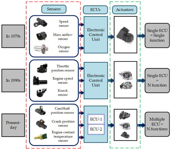
Figure 1.
Progression of electronic control units.
In order to meet customer expectations, vehicles must provide information, such as about traffic management; be easy to maintain; and provide a reliable entertainment system. Inter-vehicular communication is a subset of vehicular communication that is organised via vehicular ad hoc networks (VANETS) and controlled via wireless networks in order to facilitate communication between nearby automobiles [2]. Intelligent cars can improve traffic safety and can allow for the use of console applications by facilitating the continuous interchange of periodic and event-triggered information. Some examples of intra-vehicular communication, which is controlled through wired interfaces (LIN, CAN, and FlexRay) to exchange data between various ECUs inside a vehicle, include the global positioning system (GPS), human–machine interfaces (HMI), applications for chassis and distributed control systems, and communication features like radio and antenna. To handle time-sensitive operations like airbag deployment, a sizable number of sensors and processors are used in various regions of a vehicle. Cameras are crucial for solving larger concerns like vehicle-to-vehicle (V2V) communication and environmental sensing. A method for recognising ECUs based on distinctive signal properties that operate in the physical layer of the CAN network was proposed in [3]. Askaripoor et al. presented an analysis of the property of intra-vehicular networks in real time. According to their experimental findings, using current techniques reduces WCRT by 24% [4]. With the help of data off-loading, Internet-based services, decreased delivery delays, and dynamically choosing routing paths, Alawi et al. suggested a connectivity-aware routing protocol for VANETS. Examples include traffic management, multimedia transmissions, and vehicle-to-vehicle (V2V) communication [5].
In V2V networking and communication applications, where data are sent between vehicles through the spontaneous formation of wireless networks, VANET is primarily employed. In order to provide several services including on-road, direction-finding, and road safety services, the VANET architecture establishes V2V and vehicle-to-road-side-unit (RSU) connections. There are several scheduling schemes based on request, priority, time, deadline, and hybrid approaches with improved quality of service (QoS) to access data from vehicles associated with the VANET architecture [6]. Recently, VANETs have become appropriate for parking management and collision avoidance within the city, which may also lead to reduced CO2 emissions. In order to realise the vision of safe and secure smart cities, the regime’s participation is crucial in regulating and creating new standards in collaboration with national and international standardisation organisations for road transport, research facilities, and vehicle manufacturers. Appropriate field buses direct the data to or from the ECUs.
The integration of a hybrid gateway handles the information trail with various automobile components, converts disparate entities, and handles the diverse bus speeds. The gateway is able to discern between protocols and an abstraction of several physical layers. Due to the adaptable software architecture, automotive buses can be simply incorporated [7]. A third-party application can send and receive data on a bus using a hybrid gateway thanks to an application bus. As demonstrated in Figure 2, for high bandwidth connections to a hybrid gateway and its associated automotive buses, such as flashing and diagnostics, an Ethernet controller is used. The gateway framework offers cutting-edge utilities, including software reprogramming, vehicle calibration, and fault management [8,9]. Functional safety standard ISO26262 is met by the Automotive Open System Architecture AUTOSAR R4.0 [10] because it is based on standardised interfaces used by manufacturers. Software reusability is now impossible due to OEMs’ refusal to be transparent with developers. Because of this, AUTOSAR offers a shared software infrastructure for automotive applications that contributes to attaining goals such as decreased development time and costs, increased software reusability, and improved quality and efficiency [11]. The network should be adaptive as the ECU’s increases in complexity and the information must efficiently move throughout the network in times of congestion. Relevance techniques will therefore offer a flexible idea that operates on complex wired networks and that regulates the information flow to crucial areas.
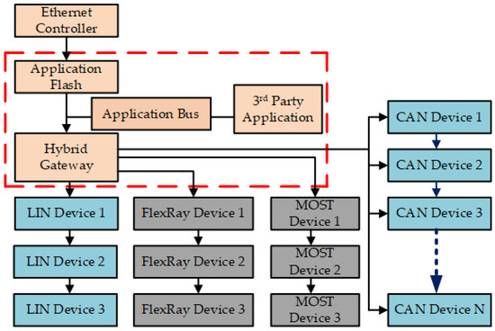
Figure 2.
Gateway associated with existing vehicular networks.
Since the automobile transmits data that it perceives to the user, these data may contain sensitive data. As a result, anonymous conversations can be prevented by validating in-vehicle reports using a pseudonym technique. The in-vehicle wired equivalents are widely scattered among the automotive networks. As a result, it increases the nodes’ obligations for successful data transport and efficient bandwidth use among the available nodes. Outstanding advancements in safety-related concerns will be made possible via our growing knowledge on how to use the GPS and wired communications in cars, and the capabilities of intra-vehicle computation and information sensing. The vehicle was designed to continuously communicate safety information to the user through voice-based communication and to provide indications in order to avoid catastrophic failure. This study includes both the CAN and LIN protocols since they offer distributed control and reduced wiring, both of which improve system performance [12].
Both approaches will guarantee a noise-free gearbox while giving the freedom to use them in various electrical configurations. Fault-free broadcast is made possible thanks to each node’s ability to check for issues with information transfer and to send the error frame. Many safety-critical programmes are built into modern vehicles, and these applications demand a lot of memory and processing power. In order to handle sophisticated data sharing across the ECUs, more built-in functionality and protocol support are available on the market for automotive microcontrollers [13]. Predominantly, the ECUs that are developed recently by utilizing 16-bit and 32-bit architectures can provide extensibility benefits for adding secondary circuits. Some of the automotive microcontroller boards can support standard specific protocols using either CAN or LIN alone [14]. However, ensuring the data flow among the ECUs is quite difficult. Considering this problem, this work completely focuses on the importance of protocol conversion between ECU-to-ECU communications. Focusing on these problems will result in a large decrease in processing time, and using AUTOSAR for standardised code development may further increase the effectiveness of code reuse [15].
In order to facilitate speedy and effective communication between control modules while simultaneously decreasing complexity, this paper’s remaining sections go over how to set up a CAN- and LIN-based central network gateway. A review of CAN and LIN interfaces in relation to error management and arbitration concepts and a description of the hybrid network gateway used to perform the protocol translation mechanism between the CAN and LIN network are covered in Section 2. Section 3 presented the simulation and hardware experimentation results to justify the contribution of this work. Finally, in Section 4, we conclude the article with a summary of the proposed work and the possibility of enhancing this work.
2. Materials and Methods
2.1. CAN and LIN Overview
2.1.1. Controller Area Network (CAN) Overview
The majority of in-vehicle communication signals are typically transferred using the CAN network. Multi-master, safety, arbitration, speed, and distance are a few of its features. For sensor-based node-connected applications, the CAN is widely used by IVNs. The CAN protocol’s comparatively low cost is the main factor in its continued use. The cost of the CAN network’s hardware has significantly decreased as a result of the market’s availability of relatively big, smart, and energy-efficient CAN transceivers. The carrier sense multiple access with collision avoidance (CSMA/CA) mechanism is used by the CAN protocol to control access to the bus (CIA, 2007). When two or more nodes want to communicate at the same time, it prevents collisions by using a priority mechanism and numerical identifiers.
Figure 3 shows how to update a recessive “one” bit on the CAN bus using a dominant “zero” bit when there are two nodes, resulting in two levels on the bus. When many nodes want to broadcast, they first scan the entire bus to determine whether anything is already happening. Nodes begin transmitting their message identifiers (most significant bit first) if the bus is idle before checking the bus levels. The recessive bit is broadcast over the bus through node A, while node B transmits a dominant bit; the bus result will be a dominant level. In this case, after gaining access to the bus, the message will be sent by the node with the lowest message identifier number. When the bus reopens, the node that lost the arbitration round must wait before transmitting the message again. The bus arbitral mechanism is used by the CAN protocol to ensure that the node with the greatest priority (lowest value in the identification field) can continue transmitting despite having to get off the bus. It illustrates that CAN works as predicted and is adept at utilising the bus bandwidth.
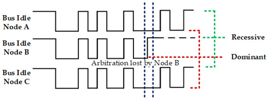
Figure 3.
Arbitration for controller area network bus.
2.1.2. CAN Error (Fault) Handling and Confinement
By remotely examining how the system responds and functions in the event of an error, system flexibility can be determined. The data delivery is secured via the use of the conventional error detection method when the receiver hands over an acknowledgment to the transmitting station, which is typically the recipient address. According to the CAN perception, every member of the network communicates and receives an identification “labelling” message, which forces every local station that is now connected to the network to perform an error check. The CAN protocol employs a permutation of positive (PACK) and negative (NACK) acknowledgments to achieve this goal [16,17]. The receiver delivers to the master node an acknowledgment based on the working output. A recipient may acknowledge a message in either a favourable or negative way. Positive ACKs are represented by dominant bits in the acknowledgment slot, and negative ACKs are represented by recessive levels in the same slot. Most crucially, the ACK delimiter will always be delivered for the sake of error tracing. As the sender sends the ACK slot and delimiter in line with the features of the message, it is permissible to accept one affirmative acknowledgment in order to guarantee the accuracy of the message transmitted to the sender. The message will finish by passing an error flag as soon as the sender detects an erroneous ACK if there is not even a single positive ACK and no recipient updates the recessive ACK slot. Either the sender or the absence of any receivers on the bus is the cause of this error. The PACK is defined by the following expression:
where, during a specific time period, PACK is transmitted from reachable nodes that correctly provide this positive acknowledgment (ACK time slot). PACK therefore indicates that at least one message transport was accomplished. The NACK indicates that at least one fault exists throughout the entire system. Each station should have two distinct error offsets (counters) at first; one will keep track of the environment when a message is transmitted. In line with the reported mistake type and the node operating conditions, the offsets are increased to various weightings and some conditions are dipped. The initial data from nodes that send information are tracked using these offsets. A station’s state could change from “error active” to “error passive” if too many errors are acquired in that station. This prevents communication between the specific station while keeping watch on any network issues that may arise. The network may become blocked if there are too many transmission faults present, rendering all transfers impossible. The error-active network node sends an active error flag through a bus link when an error is discovered. During reset, this is the node’s default state. An error-passive network node has accumulated an excessive number of transmit or receive errors. Consequently, a significantly greater error rate is continuously monitored via this node. A node that is in the bus-off state is not permitted to make any kind of influence on the bus.
A CAN node’s faulty status diagram is shown in Figure 4. After a reset, a node is in the error state. In the event of the two error counts exceeding the value 127, the monitor will ask for the MAC sub-layer and enter error-passive mode. The error count drops below 128 even while the node resumes error activity during both the receive and transmit processes. When the transmit error count exceeds 255, a node is removed from the bus, resulting in the bus-off state. After sensing 128 sets of eleven subsequent recessive bits in the off state, a node can go back to the error-active state. The error record will be immediately reset to 0 upon reset. This precaution ensures that a potentially incorrect node cannot immediately be disrupted after reset. Even at a very high busload, in proportion, an uninterrupted transmission of up to 128 more frames is possible [18].
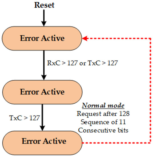
Figure 4.
Representation of the controller area network’s error states.
2.1.3. Local Interconnect Network (LIN) Overview
To significantly help in managing mechatronic components present in dispersed systems for automotive applications, the LIN protocol is suggested. LIN makes use of the master–slave architecture principle, in which there is a single master node and a set number of slave nodes. The response fields and frame header make up the LIN frame. The protected response identifier [19] is present in the header. The LIN slave responds to the frame header message sent by the LIN master by transmitting a frame. Ten bits are communicated per byte when data are transmitted in eight data bits with one start bit and one stop bit without parity.
Data on the bus are divided into the recessive (high) and dominant (low) categories, as indicated in Figure 5. The minimum voltage level at the transmitter is less than 20% of the battery voltage , or roughly 1 Volt, producing logic 0. On the other hand, logic 1 dictates that the maximum level voltage is 80% higher than the . Logic 0 is below 60% of receiver , but logic 1 is 60% greater than the . A specific slave node responds to the identification with a frame response that contains data and checksum fields. It functions as a CAN functionality at a reduced cost and data rate and with less network bandwidth. Real-time LIN connections are implemented using a “single” cable, which is less expensive than CAN in terms of connectors and cabling [20]. Through the use of CRC and error detection, LIN ensures the security of sent data and offers assured transmitted signal delay as well as daisy chain setup. In contrast to traditional UART or SCI-based systems, LIN is hence less complex and can identify problematic nodes in the network.
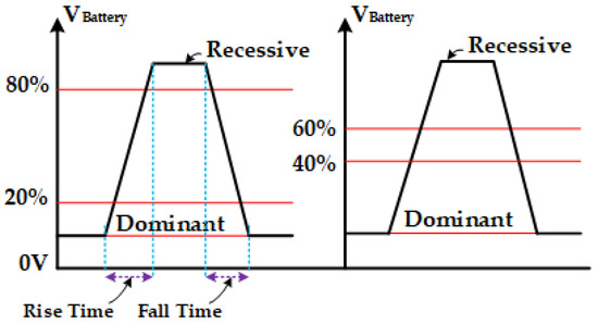
Figure 5.
Arbitration for local interconnect network buses.
2.1.4. LIN Error Signaling and Confinement
The peerless master architecture makes it unlikely for LIN to provide an error signalling tool. The erroneous data will be delivered upon request in the form of diagnostic messages, even though the errors are noted close by. The LIN nodes are able to distinguish between temporary and permanent faults, conduct their own limited diagnosis, and take corrective action. The Freescale microcontroller, which is mostly utilised in automotive applications, is employed in this work as a proof of concept. One master node and many slave nodes make up the full test bench. While overclocking to 50 MHz can quadruple the execution speed, the device’s performance was measured at 25 MHz. The system’s efficiency is entirely dependent on memory, a low-speed CAN transceiver, and computing performance [21]. Tricore controllers can be deployed to eliminate the delay in this device without using any controller bandwidth or resources. Average network efficiency can be attained via the introduction of event-triggered messages, which will help the LIN protocol’s performance problems be resolved. The main drawback is that it hinders worst-case performance and makes it difficult to diagnose the network.
2.2. Embedded Vehicular Network Gateway
Modern automobiles employ both mechanical and electronic components, which are controlled via processors. A car’s ECU will be in charge of managing the subsystems. From less urgent functions like airbag regulation and adaptive cruise control to more straightforward ones like managing wiper movement or brake lights, the ECU’s involvement may be observed in every area. Additionally, the numerous subsystems in the car are responsible for operating the processors that control the actuators and process sensor data. On-board CAN and LIN networks were created specifically to satisfy all needs. There is a potential that one specific CAN node could develop a defect when data from several ECUs are sent across the field buses to the hybrid gateway. In that case, additional nodes, irrespective of the specific node, will be capable of connecting with the gateway. In order to solve this problem and to provide an appropriate diagnostic interface with well-organized data transmission, a switch has been used with the field bus switching gateway [22]. In order to establish communication between the current field buses, the gateway’s function is crucial. Future intra-vehicular networks (IVN) will be dominated by Ethernet because if its low cost, higher bandwidth, ability to support infotainment and diagnostic systems, and ability to facilitate vehicle diagnosis [23]. Similarly, a backbone-based design has taken the position of the hybrid gateway architecture, in which each sub-network will communicate with its own domain control unit (DCU). Making a hardware–software platform that should be simple to set up and test is the most significant limitation. A new gateway should be developed for various vehicle types, and/or choices for choosing the best sub-network and gateway for a certain vehicle model should be made available. A dependable gateway will be able to address the field bus message conversion problems and to concentrate on building effective gateway technology in an OSEK/VDX environment. Xiang Li et al. analysed the various security problems from the intra-vehicular network perspective. Due to the fact that vehicles are safety-critical, more effective steps are taken into account so as to deliver driver and passenger safety [24]. In V2V communications, to gain better QoS, differentiated services and multiprotocol label switching (MPLS) are considered to perform fast switching and routing mechanism [25]. In next-generation wireless communication, vehicular networks are a key technology for applications in intelligent transportation system, safety, and multimedia applications to handle audio, video and on-road services. Safety-critical applications will require the least end-to-end latency because if a warning message arrives at the end station with a high delay, that message is useless for preventing an accident. Throughput and packet loss are two additional QoS factors that are essential in active safety applications as a result. Switching should be included in the roadside backbone network to increase end-to-end delay, packet loss, and throughput QoS metrics. While employing MPLS in nodes may improve E2E delays because of the speed with which layer headers are handled, it has its limitations for wireless nodes due to the unfavourable effects that MPLS has on overhead.
The architecture of the CAN and LIN protocols are shown cooperating as a hybrid structure in Figure 6 to increase the effectiveness of the complete car system. The CAN node alone controls the time-critical services (EMS, ABS, and SR), whereas the LIN node controls the non-critical functions. According to the single gateway method, a single gateway is in charge of both critical and non-critical applications. It represents the hybrid construction in which high-speed and low-speed applications are distinguished. The Freescale MC9S12XDP512 16-bit microcontroller is used in the proposed design to implement the CAN node in the Code Warrior IDE. Additionally, it uses the MC33661 low-speed LIN transceiver in addition to the MC33388 high-speed CAN transceiver. The CAN module is designed to replicate and ensure the delivery of the data. If a CAN node error occurs, the LIN will temporarily function until the CAN node resumes. An additional component to this architecture is the LIN node, which is intended to monitor CAN in such a way that it controls the functioning of CAN while assigning certain pins that are programmed in the microcontroller to check the node’s state. In addition to CAN protocol defects like bit errors, stuff errors, acknowledge errors, and CRC mistakes, CAN gateway problems can also result from software gateway failure. The CAN gateway will detect any of these faults right down to the kernel code of the CAN driver. Additionally, the CAN transmission and reception failures will be detected via the kernel and tracked using the programme.
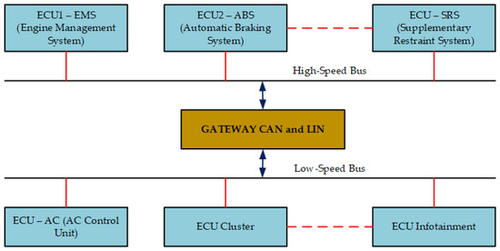
Figure 6.
Architecture for CAN/LIN using a single gateway.
For the CAN malfunctions owing to gateway problems or CAN protocol faults, the connection intended for the LIN gateway is shown in Figure 7 as a red line. In contrast, when LIN fails, the green lines show the connection for the CAN gateway. Due to the simplicity of the software architecture, the CAN and LIN gateway jointly receive the critical and non-critical signals from the ECUs to support their own operation, unless a problem is discovered in either gateway. The internal buffers designed within the CAN and LIN gateway software will store the data from the applications. During a failure, these data buffers will be modified for inputs from CAN or LIN ports. Data mismatch will not happen anymore because both gateways have exclusive local buffers for each of their respective apps. The following can be used to analyse the CAN bus’s performance when a wire problem occurs. Every time an ECU transmits data on the bus, the transceiver will identify a bit mistake and move it to the dominant state. As a result, the resistance of the wire experiences a voltage drop. The resistance or voltage drop needs to be checked frequently in order to find wire faults. As a result, the four-wire Kelvin resistance method is widely used to evaluate wire resistance. Compared with the two-wire resistance-measuring method, this method will reduce the measurement error by 20%.

Figure 7.
Model for hybrid gateway architecture.
It is first necessary to measure the voltage and current in order to determine the wire’s resistance. A voltage measurement can be made by looking from various angles, while the current on the CAN bus is measured using a cheap shunt resistor. Utilizing the time domain reflectometry (TDR) method, the CAN cable fault is located. The identical broadcast signal will be absorbed at the other end stages of the reflections if the CAN cable (twisted pair) has normal impedance, which means there will not be any reflections in the cable. If the connection’s impedance changes, the transmitted signal will be reflected back to the source. The reflected signal may have a lower impedance than the received signal, which has a lower impedance. In addition to the resistance change, cable loss can also affect the reflection’s amplitude. The difference in reflected signal times is meant to represent the length of the cable, and the variation in amplitude is regarded as the fault intensity. The T connection is used to implement the TDR technique, the connector contains the signal, and the other end of the cable were tested. The connector’s top end needs to be connected to the apparatus that determines the signal’s magnitude and timing.
The CAN stress hardware from Vector is used to generate the CAN protocol error in order to visualise the outcome. The programme will increase the TX/RX error count as well as the error frames produced via the CAN. The LIN gateway software will notice that there is a CAN failure as the error count increases. The CAN gateway promptly verifies the data that were transmitted at the moment of the fault by checking its internal buffers. The LIN gateway will then begin broadcasting both its own service messages and the CAN failure message throughout the network. Software is used to convert the CAN to the LIN protocol. When the CAN component starts functioning again, the LIN node will send the original frame it was sending and notify the CAN port to use it.
Figure 8 shows the flow of the gateway module, which first checks for errors before executing the CAN to LIN signal translation for the fault-tolerant bridge network. In Section 2.2.1, the CAN to LIN translation algorithm is described.
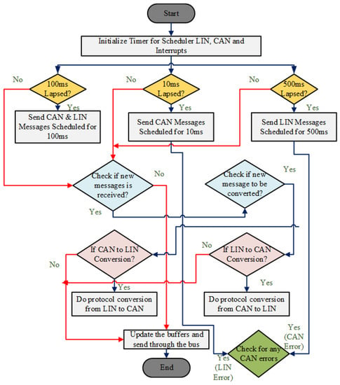
Figure 8.
Gateway module functional flow diagram.
2.2.1. CAN to LIN Conversion Algorithm
- Under the programme code, the CAN and LIN device driver implementation files will be accessed.
- The scheduler part, which is created as a time slice in the programme and runs in intervals of 10 ms, 200 ms, 500 ms, and 1000 ms depending on the clock frequency of the microcontroller, implements the gateway function. The oscillator clock frequency in the proposed gateway design is 25 MHZ.
- The interrupts in the CAN are set up, and buffers are received so that the message frames can be sent and received, respectively, as well as the LIN timers for 10 ms, 100 ms, and 500 ms in the scheduler.
- If the timers are running out, as demonstrated in step 3, the message frames that need to be transferred to the CAN buffers are sent, which will send the message frames and the data in the CAN data bus. The scheduler maintains the CAN message frames’ periodicity. The LIN is treated in the same way.
- The messages regularly received on the CAN or LIN bus lines are checked.
- It should be moved from the local software buffers into the CAN and LIN buffers.
- Whether the CAN to LIN conversion is necessary is determined. Whether a fresh message is received in the CAN node determines whether this choice will be taken. If so, the node linked to the LIN network will obtain the data from the CAN bus.
- Software is used to convert CAN to LIN if necessary (typically, data that are moved to local buffers are transformed to the LIN data format and delivered to the LIN network).
- The buffers are refreshed and sent across the necessary network.
- The CAN is inspected for any protocol issues. Device driver software is used to perform this error checking.
- During an error sequence, the error counter is raised and a failure message is sent on the bus and is sent via LIN or CAN.
- Step 11 is repeated until the CAN/LIN errors are corrected.
2.2.2. Intra-Vehicular Security Principles
Numerous vehicular applications will necessitate source-to-destination communication security as an aiding environment in future [26]. It is imperative that all transferred information be viewed by only the designated recipients, and it is necessary to block any attempts by unauthorised users to modify the system in order to participate in vehicular communication. In order to address in-vehicle security challenges, contemporary security methods can offer high levels of integrity, confidentiality, and authentication based on challenging cryptography protocols and algorithms. The most fundamental ways used to achieve secured communication in vehicular bus are through proper authentication, encrypted data communication, and gateway firewalls [27]. The authentication factor in automotive bus systems requires that only valid controller devices are able to communicate; if any unauthorized message is found during the processing stage, those messages are simply discarded. Thus, every device needs authentication confirmation against the gateway as a valid transmitter. The gateway securely holds public keys of all devices accredited by OEMs of the individual vehicle to authenticate the validity of the device. The hybrid gateway in the work links the entire bus system with each other, and data transfer is performed exclusively through the processor gateway.
The CPU contains a protected memory area where the public keys and necessary authorizations can be safely stored. In order to provide source authentication and message integrity and so that each device might add a MAC code to each message, each controller device may receive the same authentication key from the gateway. The timing requirements and computing power will likely be exceeded in the majority of automotive microcontrollers when taking into account an asymmetric scheme. Additionally, in order to strengthen security, the gateway must periodically start key updates. This stops unauthorised controllers from using symmetric keys that are already well known. To notify all controllers of a bus system, a message encrypted with the individual public key of each controller, the gateway transmits for every single controller on its recent list of usable controllers. Contrarily, as soon as each controller has decrypted the key sequence by using a secret key, a final message will be broadcast from the gateway to activate the updated symmetric keys. A firewall is another factor to guarantee security in vehicular communications. If the controller device utilized in the design is implemented for handling MAC or digital signature features, these devices can only direct valid messages into the vehicular bus systems. In the case if a controller device not implemented with MAC, the firewall rules can be recognized only based on the permissions from each subnet.
3. Results
Sensor Interfacing with MC9S12XDP512 Microcontroller
Considering the sensors used for automotive applications, silicon sensors are used for the measurement of gases, air, and fluids for temperature measurement within the range of 50 to 150 °C. When measuring very high temperatures above 1050 °C, both the resistance temperature detector (RTD)-type and thermistor-type sensors can be utilized, which comply with OBD regulations for catalyst overheat monitoring. In the MC9S12XDP512 microcontroller, the engine coolant sensor (thermistor) is interfaced with input–output port address 0x02C0 to continuously monitor the coolant temperature and to ensure whether the engine is running at the optimal temperature. The temperature, speed, and pressure sensors are linked in the device register address map, ranging from 0x02C0 to 0x02DF.
Figure 9 illustrates the operational sequences carried out right after the pressure sensor crosses the threshold level. In the luxury vehicle segments, according to the regulations of NHSTA, airbags are designed to be deployed in frontal and near-frontal crashes for a minimum deceleration of 23 km/h (14 mph). ABCM used in automobiles will ensure and enhance the safety of the passengers travelling in the vehicle. This system is controlled via the body control module where a pressure sensor (3Q0959354) is placed on the bonnet of the automobile; whenever a moderate or severe crash occurs, a signal is transmitted from the ECU of the airbag system to an inflator in the airbag module.
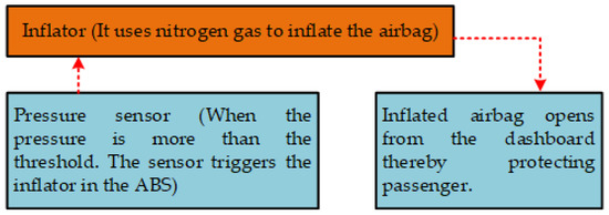
Figure 9.
Illustration of the sensor operation block.
When the vehicle crashes, the pressure sensor in the hood measures the pressure level. If the pressure level is more than the threshold, then the inflator inside the steering wheel is activated and the airbag starts inflating with nitrogen gas. When the bag fills up, it comes out from front end in the interior of the vehicle; therefore, catastrophic damage to the passenger can be avoided. In this system, a pressure sensor is connected to the port AD input of the port address 0x02C2 mapped in the device to monitor the pressure level during the crash. Vehicle speed sensors (VSSs) are used to gauge the rotational speed of a shaft or disc. It generates a magnetic pulse that is proportionate to the vehicle’s speed in the shape of a wave (i.e., when a vehicle moves quickly, the VSS will produce a high-frequency signal that is exactly proportionate to the vehicle’s speed). The power control module controls the torque, clutch lock-up, fuel injection, ignition, and operation of the cruise control system using the magnetic pulses frequency signal. The VSS will produce four pulses for every revolution of the magnet when a vehicle is moving. The speed sensor, which is connected to the speedometer cable, is placed on the vehicle’s axle and wheel. The VSS is powered by a magnet attached to the gearbox case’s back, behind the speedometer. While the other side of the VSS is wired to a spinning magnet that produces a voltage and transmits it to an MC9S12XDP512 device that calculates the speed proportional to the moving vehicle, the top section of the VSS senses the transmission output. The port AD input in the device register memory map address 0x02C4 is connected to the vehicle speed sensor to measure the vehicle’s speed.
By connecting CAN buses using Vector CANoe, the time required to transmit messages is evaluated, and the system etiquette is successfully tested. The bus is monitored via the Vector CANoe for things like peak load and error frames. The CAN bus is connected to Vector CANoe using the CANcaseXL hardware by collecting pins from channel 2.
As shown in Figure 10, the value 75 (75 degrees Fahrenheit) indicates the amount of heat that the engine radiates. The MC9S12XDP512 microcontroller has ATD0 (ADC 10-bit, 8-channel) and ATD1 (ADC 10-bit, 16-channel) with sizes of 32bytes and 48bytes. The temperature sensor is interfaced to the port AD input–output with an ATD0 8-channel ADC in the device register address map 0x02C0. The MC9S12XDP512 Freescale device is used to examine the fault-tolerant and intelligent gateway, and the goal is achieved. Automotive serial interface testing is performed using the CANoe development environment.
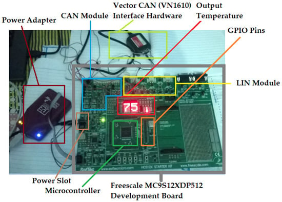
Figure 10.
Connected hardware board for bus monitoring with vector CANcaseXL.
Figure 11 shows a CAN–CAN (C2C) gateway, in which the CAN ID (2CC) is sent to CAN channel 1 via simulation from the IG block of the Vector CANalyzer. The identical message is picked up by a different channel and returned to the CAN ID 100 in the Vector CANalyzer tracing panel.
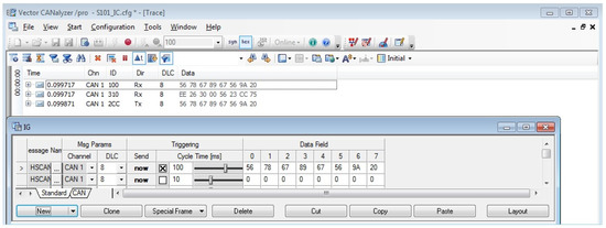
Figure 11.
Transmission and reception of CAN messages (refer to CAN ID).
Figure 12 depicts the process of decoding the CAN packet ID 0x2CC that is presented in the LECROY wave surfer. The collected waveform verifies the frame by using the start of the frame, data bytes, and the CRC aligned for the final byte of the frame with bit stuffing.
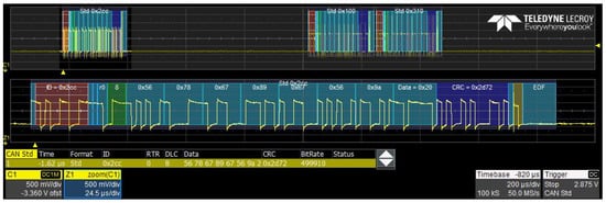
Figure 12.
LECROY-bus-analyzer-captured CAN message frame.
The LIN transmission with message ID 0x01 is shown in Figure 13. The resynchronisation, ID number, and data bytes are displayed during the decoding of a LIN frame.
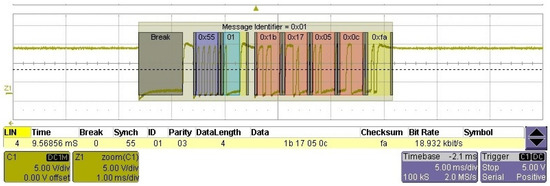
Figure 13.
LECROY scope used to capture LIN frame.
The CAN gateway failure seen in Figure 14 was caused by combining the CAN High and CAN Low lines, which allowed erroneous frames to be sent over the bus. In addition, protocol failure of the C2C gateway occurred because zero messages were collected in the CAN bus while broadcasting.
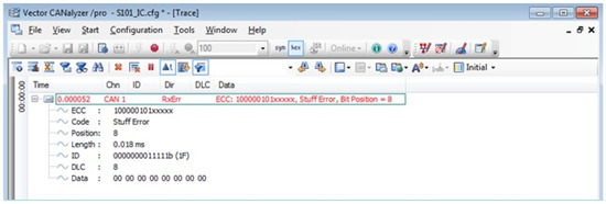
Figure 14.
Vector CANalyzer captures CAN error frame.
Figure 15 shows a CAN bus error frame. Figure 16 depicts a simulation of the Freescale Code Warrior IDE’s true time simulator (debugger). In this case, a LIN gateway will be successful in retrieving and transmitting the CAN messages that are now in an incorrect status. An arbitration mechanism is used in CAN due to which collisions will not occur. The controller is responsible for receiving the data frames. The software must be programmed accordingly to read data frames before the frames are overwritten by the next frame.
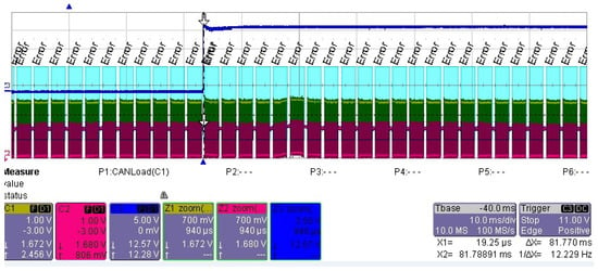
Figure 15.
LECROY scope used to capture CAN bus error frames.
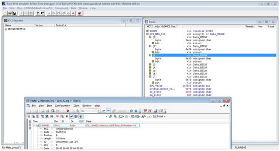
Figure 16.
LIN message transmission using real-time debugger while CAN node contains error frames.
The LIN bus has been tested in the network with the CAN bus gateway in an error condition and transmitting CAN data frames (this will be translated and framed in the form of LIN messages based on CAN data), as illustrated in Figure 17.
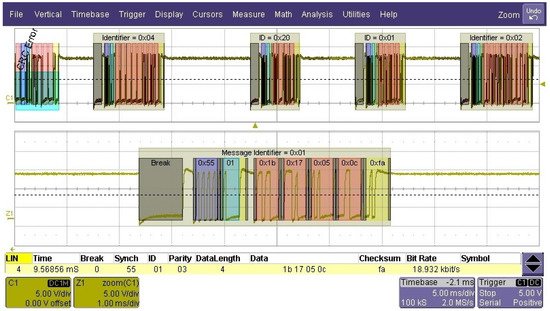
Figure 17.
LIN message transmission using LECROY scope while CAN node has error frames.
As a result, temporary gateway failure and bus deterrents are limited. In a hybrid architecture, the networks have reliant communication with low cost and good performance; the recommended gateway will therefore be advantageous.
We also evaluated the work by interfacing the external LM35 temperature sensor with Spartan3E FPGA. The CAN bus input–output signals are interconnected with an LM35 sensor that produces an analog output voltage that is proportional to temperature. An expansion port on the Spartan-3 FPGA allows multiple boards to be plugged into the expansion bus. A processor, memory, and other peripherals may be present on the board that is connected to the expansion bus. The extension bus-connected board and the FPGA can work together to build a temperature monitoring system.
Not everything needs to be created from scratch when designing an FPGA-based CAN system. A proprietary core can be used to implement the CAN interface. An IP core is a functional module that has already been created and tested and can be inserted into an FPGA with the application logic. CAN IP cores have unique characteristics and capabilities, just like standalone and embedded CAN controllers. Many CAN nodes offer basic analogue or digital I/O functionalities. To connect the peripheral functions to the CAN bus, these nodes do not need a complex CPU. To complete the task, a straightforward FPGA with a CAN controller and customized peripherals is used. An FPGA only has digital logic and lacks on-chip non-volatile storage; hence, several extra parts could help to offer some common functions:
- The node ID and other device configuration are kept in an external EEPROM.
- The implementation of analogue interfaces uses external A/D and D/A conversion elements.
A local DMA controller can be included to solve the constraint at the system interface. Outgoing CAN messages are now directly obtained from the system memory-based transmit queue, while incoming CAN messages are filtered and sent to the system memory without requiring CPU interaction. Since CAN messages are transmitted as 32-bit wide data bursts, a DMA-based data transfer not only reduces the amount of interrupts but also enables a considerably more efficient transfer. It is crucial while using FPGAs to construct a external digital communication mechanism. A typical digital protocol will support examining everything from individual byte translations to the preferred connector type. After passing through several abstraction layers, the actual electrical properties related to each I/O pin are eventually discovered. Digital logic levels, for instance, could be straightforward TTL (transistor–transistor logic) lines of 5 V or 3.3 V with single-ended signalling that refers to a common ground. Ground referenced inputs are utilised to lessen the number of data pins required, but because they are more sensitive to noise, they cannot be utilised over long distances and may increase the cost of line drivers and cabling. For communication up to 4000 feet, digital protocols like RS-485 use differential signalling between −7 and 12 volts. When interacting with an FPGA chip, depending on the protocol being used, additional circuitry for signal conditioning and to amplify or attenuate electrical signals may need to be included.
The five digital I/O lines have been CLOCK, COMMAND, DATA, SELECT, and ACK. The command line on the game console is used to send commands to the controller, often inquiring about the device ID as well as the status of all input devices. Each command is composed of eight bits or one byte and is displayed in hexadecimal format. The required information is subsequently returned by the data line in a string of eight bytes. Each byte contains a record of every switch’s current state. By going low and staying low throughout the transmission, the SELECT line, the third line in use, only captures the controller’s concern. The controller sends a console acknowledgment after each byte on the DATA line, and the fourth line is the ACK line. The controller also generates the CLOCK line to keep all communication in sync.
4. Conclusions
With the use of the Vector CANoe tool and Freescale hardware, this paper provides an understanding of the CAN and LIN protocol ideas. The impact of this gateway-based strategy during the early stages of the development process aids in diagnosing the IVN, saving a substantial amount of design time. Due to increasing wire length and complexity, it is advantageous that the ECU modules are positioned in accordance with the vehicle gateway specifications to prevent data loss. The CAN and LIN networks will benefit from the gateway outlined in this article. For the experimental investigation shown in the preceding sections, a strict effort was made to enhance the gateway performance and to fix any issues that arise when the ECUs share data over intra-vehicular networks. The hardware result shown in Section 3 gives the pictorial view of the MC9S12XDP512 board for the establishment of communication among the ECUs. The data collected from different sensors are shared between one ECU to another through dedicated wires to reduce processing time. In order to overcome the fault condition, the software written for the gateway-based approach will provide efficient data delivery through the appropriate protocols.
The methods described in this article can be expanded for use with other intra-vehicular networks as part of future development. In consideration of market opportunities, communications taking places within a vehicle segment have been growing steadily from the early days where one ECU interacts with another ECU. In the past decade, due to higher bandwidth, the popularity of the CAN and LIN protocols have grown evermore and they have become accepted standards for the establishment of communication between ECUs. The existing vehicular networks such as CAN, LIN, FlexRay, Automotive Ethernet, and MOST are wired technologies used for communication among several electronic control units present inside the vehicle, while transformations into wireless communication technologies (Wi-Fi and ZigBee) within the ECUs may lead to a reduction in cost, weight, and wiring harness. Moreover, vehicle diagnoses become simple and provide higher levels of scalability. The major drawbacks are that it requires additional circuitry to set up, thereby having much complexities in the design and less security. The adoption of CAN and LIN for vehicular applications is completely inevitable in the present scenario, not only as it provides a bandwidth benefit but also due to its low cost and higher flexibility. Additionally, the CAN FD protocol can be used for applications requiring higher bandwidths and a payload of up to 64 bytes, which are better suited for sophisticated sensor systems and bid-like advantages.
Author Contributions
R.K. developed the proposed research concept, completed the study, obtained the results, and wrote the article; J.L.M. contributed his experience in intra-vehicular networks for further development and verification of the theoretical concepts and was involved in providing suggestions for writing the article; B.C. was involved in setting up the tasks for the study, assisted the authors in implementing and verifying the proposal as a supervisor, was involved in developing the concept, and wrote the article as a co-author. All authors have read and agreed to the published version of the manuscript.
Funding
This work was supported in part by the Department of Science and Technology, Government of India, Promotion of University Research and Scientific Excellence (PURSE), under Award SR/PURSE/2021/65.
Conflicts of Interest
The authors declare no conflict of interest.
References
- Khan, J. Design of a High Efficiency In-Vehicle Network with a Single ECU for a Network (SEN); Technical Report; SAE Technical Paper: Warrendale, PA, USA, 2014. [Google Scholar]
- Kurugollu, F.; Ahmed, S.H.; Hussain, R.; Ahmad, F.; Kerrache, C.A. Vehicular Sensor Networks: Applications, Advances and Challenges. Sensors 2020, 20, 3686. [Google Scholar] [CrossRef] [PubMed]
- Choi, W.; Jo, H.J.; Woo, S.; Chun, J.Y.; Park, J.; Lee, D.H. Identifying ecus using inimitable characteristics of signals in controller area networks. IEEE Trans. Veh. Technol. 2018, 67, 4757–4770. [Google Scholar] [CrossRef]
- Askaripoor, H.; Hashemi Farzaneh, M.; Knoll, A. E/E Architecture Synthesis: Challenges and Technologies. Electronics 2022, 11, 518. [Google Scholar] [CrossRef]
- Alawi, M.; Alsaqour, R.; Abdelhaq, M.; Alkanhel, R.; Sharef, B.; Sundararajan, E.; Ismail, M. Adaptive QoS-Aware Multi-Metrics Gateway Selection Scheme for Heterogenous Vehicular Network. Systems 2022, 10, 142. [Google Scholar] [CrossRef]
- Wahid, I.; Tanvir, S.; Ahmad, M.; Ullah, F.; AlGhamdi, A.S.; Khan, M.; Alshamrani, S.S. Vehicular Ad Hoc Networks Routing Strategies for Intelligent Transportation System. Electronics 2022, 11, 2298. [Google Scholar] [CrossRef]
- Tuohy, S.; Glavin, M.; Hughes, C.; Jones, E.; Trivedi, M.; Kilmartin, L. Intra-Vehicle Networks: A Review. IEEE Trans. Intell. Transp. Syst. 2015, 16, 534–545. [Google Scholar] [CrossRef]
- Rathore, R.S.; Hewage, C.; Kaiwartya, O.; Lloret, J. In-vehicle communication cyber security: Challenges and solutions. Sensors 2022, 22, 6679. [Google Scholar] [CrossRef]
- Kim, J.H.; Seo, S.H.; Hai, N.T.; Cheon, B.M.; Lee, Y.S.; Jeon, J.W. Gateway Framework for In-Vehicle Networks Based on CAN, FlexRay, and Ethernet. IEEE Trans. Veh. Technol. 2015, 64, 4472–4486. [Google Scholar] [CrossRef]
- Sini, J.; Violante, M.; Tronci, F. A Novel ISO 26262-Compliant Test Bench to Assess the Diagnostic Coverage of Software Hardening Techniques against Digital Components Random Hardware Failures. Electronics 2022, 11, 901. [Google Scholar] [CrossRef]
- Hamed, A.; El-Kharashi, M.W.; Salem, A.; Safar, M. Two-layer bus-independent instruction set architecture for securing long protocol data units in automotive open system architecture-based automotive electronic control units. Electronics 2022, 11, 952. [Google Scholar] [CrossRef]
- Bozdal, M.; Samie, M.; Aslam, S.; Jennions, I. Evaluation of can bus security challenges. Sensors 2020, 20, 2364. [Google Scholar] [CrossRef] [PubMed]
- Bedretchuk, J.P.; Arribas Garcà a, S.; Nogiri Igarashi, T.; Canal, R.; Wedderhoff Spengler, A.; Gracioli, G. Low-Cost Data Acquisition System for Automotive Electronic Control Units. Sensors 2023, 23, 2319. [Google Scholar] [CrossRef] [PubMed]
- Shon, T. In-Vehicle Networking/Autonomous Vehicle Security for Internet of Things/Vehicles. Electronics 2021, 10, 637. [Google Scholar] [CrossRef]
- Sundharam, S.M.; Iyenghar, P.; Pulvermueller, E. Software Architecture Modeling of AUTOSAR-Based Multi-Core Mixed-Critical Electric Powertrain Controller. Modelling 2021, 2, 706–727. [Google Scholar] [CrossRef]
- Bi, Z.; Xu, G.; Xu, G.; Wang, C.; Zhang, S. Bit-Level Automotive Controller Area Network Message Reverse Framework Based on Linear Regression. Sensors 2022, 22, 981. [Google Scholar] [CrossRef]
- Zhang, H.; Meng, X.; Zhang, X.; Liu, Z. CANsec: A practical in-vehicle controller area network security evaluation tool. Sensors 2020, 20, 4900. [Google Scholar] [CrossRef]
- Kim, H.J.; Lee, U.; Kim, M.; Lee, S. Time-synchronization method for CAN–Ethernet networks with gateways. Appl. Sci. 2020, 10, 8873. [Google Scholar] [CrossRef]
- Hbaieb, A.; Rhaiem, O.B.; Chaari, L. In-car Gateway Architecture for Intra and Inter-vehicular Networks. In Proceedings of the 2018 14th International Wireless Communications & Mobile Computing Conference (IWCMC), Limassol, Cyprus, 25–29 June 2018; pp. 1489–1494. [Google Scholar]
- Peng, Y.; Shi, B.; Jiang, T.; Tu, X.; Xu, D.; Hua, K. A Survey on In-vehicle Time Sensitive Networking. IEEE Internet Things J. 2023, 10, 14375–14396. [Google Scholar] [CrossRef]
- Xu, Y.; Shang, J.; Tang, H. Recent trends of in-vehicle time sensitive networking technologies, applications and challenges. China Commun. 2023, 1–26. [Google Scholar] [CrossRef]
- Rșteiu, M.; Dobra, R.; Avram, A.; Samoil, F.; Buic, G.; Rizzo, R.; Micu, D.D. Designing a Smart Gateway for Data Fusion Implementation in a Distributed Electronic System Used in Automotive Industry. Energies 2021, 14, 3300. [Google Scholar] [CrossRef]
- Bui, V.T.; Dow, C.R.; Huang, Y.C.; Liu, P.; Thai, V.D. A Canopen-based gateway and energy monitoring system for electric bicycles. Energies 2020, 13, 3766. [Google Scholar] [CrossRef]
- Li, X.; Yu, Y.; Sun, G.; Chen, K. Connected vehicles’ security from the perspective of the in-vehicle network. IEEE Netw. 2018, 32, 58–63. [Google Scholar] [CrossRef]
- Hassan, M.K.; Syed Ariffin, S.H.; Ghazali, N.E.; Hamad, M.; Hamdan, M.; Hamdi, M.; Hamam, H.; Khan, S. Dynamic Learning Framework for Smooth-Aided Machine-Learning-Based Backbone Traffic Forecasts. Sensors 2022, 22, 3592. [Google Scholar] [CrossRef] [PubMed]
- Siddiqui, A.S.; Lee, C.C.; Che, W.; Plusquellic, J.; Saqib, F. Secure intra-vehicular communication over CANFD. In Proceedings of the 2017 Asian Hardware Oriented Security and Trust Symposium (AsianHOST), Beijing, China, 19–20 October 2017; pp. 97–102. [Google Scholar] [CrossRef]
- Xie, G.; Yang, L.T.; Liu, Y.; Luo, H.; Peng, X.; Li, R. Security Enhancement for Real-Time Independent In-Vehicle CAN-FD Messages in Vehicular Networks. IEEE Trans. Veh. Technol. 2021, 70, 5244–5253. [Google Scholar] [CrossRef]
Disclaimer/Publisher’s Note: The statements, opinions and data contained in all publications are solely those of the individual author(s) and contributor(s) and not of MDPI and/or the editor(s). MDPI and/or the editor(s) disclaim responsibility for any injury to people or property resulting from any ideas, methods, instructions or products referred to in the content. |
© 2023 by the authors. Licensee MDPI, Basel, Switzerland. This article is an open access article distributed under the terms and conditions of the Creative Commons Attribution (CC BY) license (https://creativecommons.org/licenses/by/4.0/).