Article

A Universal Parametric Modeling Framework for Electric Machine Design

1
Shenzhen Institutes of Advanced Technology, Chinese Academy of Sciences, Shenzhen 518055, China
2
School of Mechatronic Engineering and Automation, Shanghai University, Shanghai 200444, China
*
Author to whom correspondence should be addressed.
Energies 2023, 16(16), 5897; https://doi.org/10.3390/en16165897
Submission received: 11 July 2023 / Revised: 5 August 2023 / Accepted: 8 August 2023 / Published: 9 August 2023
(This article belongs to the Section I: Energy Fundamentals and Conversion)

Abstract

:
At present, the majority of electric machine design software employs its own unique machine data structure. However, when users need to transfer their designs between software, they are often faced with significant obstacles or cannot obtain a parametric model suitable for optimization. In order to solve this issue, a universal parametric modeling framework is proposed for electric machine design. The geometric structure is strictly constrained to ensure that the model will not interfere with each part because of the randomness of input parameters. A data structure consisting of points, lines, and surfaces is constructed, and a conversion interface for parametric modeling with different software is established. Consequently, this universal framework can automatically generate parametric models appropriate for different finite element analysis (FEA) software according to the input parameters. The framework is especially convenient for users who need to design or optimize an electric machine, particularly when FEA software is required for verification. Numerical verification is performed using different software based on interior permanent magnet (IPM) synchronous machines to demonstrate the effectiveness of the framework.

1. Introduction

Electric machines are widely used in various applications of human daily life, and the design of these machines is a complex process that encompasses various aspects, such as structural, electrical, magnetic, and thermal considerations. Traditionally, the design of electric machines has relied on numerical calculations based on engineering experience. However, such designs may deviate significantly from the expected performance because of the nonlinearity of the process of magnetization, which has multiple variables and strong coupling properties. Based on the conventional electric machine design theory, the equivalent magnetic network model (EMN) is an optimal choice instead of the conventional analytical calculation method [1,2]. The EMN inherits the advantage of fast calculation speed, the nonlinear property of the magnetic circuit is considered, and the calculation accuracy is improved. With the advent of the finite element method (FEM) and its application in electromagnetism, various finite element analysis (FEA) software options are now being employed in electric machine design. Some of this FEA software is commercially available, such as Ansys Maxwell [3,4], Ansys Motor-CAD [5], and JMAG [6], while others are open-source, which can be freely accessed, used, and changed, such as GetDP [7] and FEMM [8]. Compared to traditional design methods, FEA offers higher accuracy and can be used in the initial design process, thereby shortening the design cycle and reducing design costs. Moreover, it is also possible to break the traditional top–bottom design approach and use FEA in the bottom–up approach for electric machine reverse design problems [9].
However, different FEA software has its own independent electric machine data structure, which may lead to difficulties when attempting to transfer models between different programs. Authors in [10] presented a technique of FEM for electromagnetic field computation, which covers program structure, data structure, and an algebraic matrix equation solver. This empowers multiple developers to work on different solvers and share common algorithms. The electric machine model established in one software may only be able to import the geometric structure into another one and then reset the excitations, materials, and boundary conditions before it can be calculated normally. As for the armature excitations setting, designing, rating, and choosing winding systems for electrical machines is developed using a tool named SWAT-EM. The SWAT-EM tool is based on the mathematical formulation of a winding layout arrangement [11,12]. Electric machines primarily utilize materials such as iron, permanent magnets (PMs), and copper [13]. Achieving accurate material modeling is crucial within FEA software [14]. FEA models can either be comprehensive or symmetrical, with periodic boundaries employed to enhance computational efficiency [15].
A large amount of software realizes the transformation of geometric models mainly through drawing interchange file (dxf) format or based on Solidwork software [16,17]. However, the new model is not a parametric model and needs to be reparametrized to be used for optimization, which is tantamount to re-establishing a new electric machine model. Therefore, it is very necessary for users to generate a new parameterized model directly when the FEA model in one software needs to be transformed into another. In addition, the parametric modeling methods are also helpful for electric machine design based on artificial neural networks (ANNs), machine learning, deep learning, reinforcement learning, and evolutionary optimization [18,19,20,21,22]. All the data drive methods can be used for inverse problems in the electric machine design to speed up the design process.
In this paper, a universal parametric modeling framework for electric machine design is proposed. The framework defines specific data structures, including geometric structure, excitations, materials, and boundary conditions, among others. The framework can comprehend what the electric machine is depending on from user input exactly and generate the corresponding FEA model. Additionally, the framework deals with the issue of geometric constraints by imposing strict mathematical constraints, enabling the realization of parametric modeling for the electric machine. One of the key features of the framework is its ability to generate parametric models suitable for different FEA software or for transferring models between different software. This allows for flexibility and compatibility in electric machine design and optimization processes. To validate the effectiveness of the framework, numerical validation is performed using an interior permanent magnet (IPM) synchronous machine.

2. Electric Machine Parametric Modeling

2.1. Electric Machine Data Structure

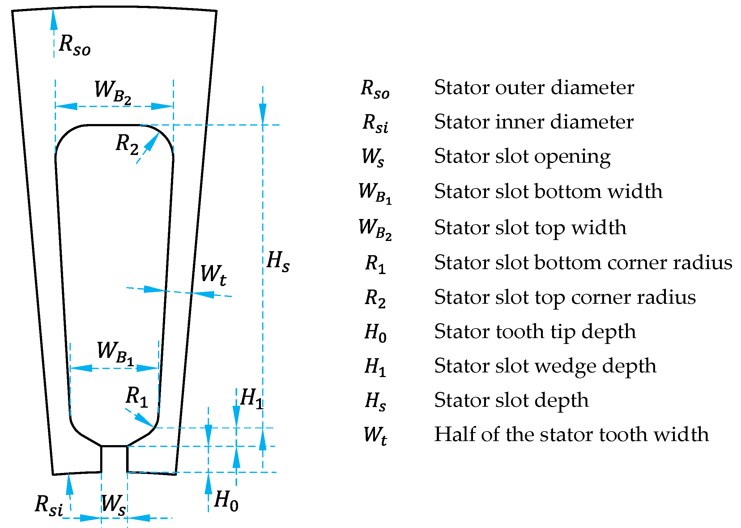
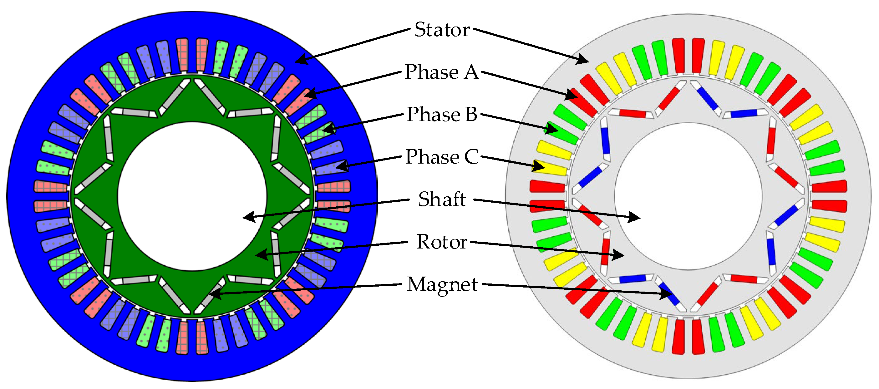
2.1.1. Geometric Structure

The geometric structure of the model primarily consists of three classes: points, edges, and faces. Points serve as the foundation of the geometric structure, and their spatial position is determined by a coordinate system, such as Cartesian or polar coordinates. To achieve parametrization, the positions of the points can be changed by the user or through optimization.
The edge class encompasses various structures, including lines, splines, center arcs, and three-point arcs. The bottom layer of each edge is defined by the points within a Cartesian or polar coordinate system. A line can be composed of multiple straight lines or arcs. For instance, two points determine a straight line, while three points determine two straight lines. By connecting the coordinate points in sequence, a line is formed. A center arc is determined by three parameters: the starting point, the center point, and the angle. The starting point defines the initial point of the arc, the center point controls the curvature of the arc, and the angle controls the extent of rotation. A three-point arc is a curve formed by three points in the coordinate system. Three points uniquely determine a circle. It is important to consider the sequence direction of the points, as mistakenly defining an outer arc as an inner arc is possible. These geometric structures provide the foundation for creating a parameterized model in the framework.
The face class comprises various closed-face structures, including rectangles, circles, ellipses, triangles, regular polygons, and other similar shapes. Regular-face structures are created by combining straight lines and arcs from the layer below and encapsulating them into independently callable geometric face structure functions. On the other hand, irregular-face structures can be constructed by connecting irregular lines. This means that any face can be drawn by connecting the underlying lines. Regular faces or predefined irregular faces can be readily accessed through their respective interface functions. There are several advantages to this approach. Firstly, it improves program execution speed by providing optimized functions for generating regular-face structures. Secondly, it offers a high level of convenience to users, allowing them to easily create and manipulate geometric faces. Lastly, this method enables the straightforward calculation of face graphic parameters, such as area and center of gravity, which can be beneficial for subsequent analysis and computations.
Indeed, it is important to consider the decision of whether to form a closed face or a single closed line when dealing with graphics composed of four lines. The rectangle structure specifically addresses this consideration by determining whether the lines should be covered to form a face or remain as individual closed lines. In the line class, there can be a judgment mechanism to determine whether the lines can be combined to form a closed graphic. This involves verifying if the figure constitutes a closed shape. For circles, the determination of whether a face is formed can be accomplished with just two parameters: the center and the radius. By utilizing these parameters, a unique circle face can be determined. To address the distinction between closed lines and faces, an additional parameter called “Is Close” can be introduced. This parameter can determine whether the formed lines represent closed lines or closed faces. These functionalities can be achieved through class utilization. By employing inheritance between classes, relationships between different classes can be established. Additionally, polymorphism can be employed to implement methods with the same name but different parameters, enabling user-input parameters to act as class constructors. These concepts of class inheritance, polymorphism, and parameter-driven constructors allow for the implementation of a robust framework that can effectively handle the creation and differentiation of closed lines and faces.

2.1.2. Excitations

The excitations mainly include windings and permanent magnets (PMs). The commonly used three-phase IPM machine is used here as an illustration example. The number of slots per pole per phase q can be expressed as
q = Q 2 p m
where Q is the number of slots, p is the number of pole pairs, and m is the number of phases.
The winding in electric machines can be either distributed winding or concentrated winding. In a three-phase winding system, the coil connections between the A, B, C, X, Y, and Z vectors determine the flow direction of each coil. To clarify, the first coil in the A vector is connected to the first coil in the X vector. Similarly, the second coil in the A vector is connected to the second coil in the X vector, and so on. This pattern continues for all coils within the A and X vectors. The same principle applies to the B and Y vectors, as well as the C and Z vectors. By establishing these connections between the corresponding coils in the A-X, B-Y, and C-Z vectors. Both double-layer and single-layer windings can be determined in this way. Different slot types, including dome slots, straight-side slots, and straight-side chamfered slots, are considered. In each slot, copper wire coils are placed, and excitation is applied to each coil to create the desired magnetic field.
In the case of a 12-slot IPM machine with a single-layer winding, the winding arrangement of the slots can be depicted using star notation with different coil pitches, as shown in Figure 1. It is important to note that in this example, the positive direction is assumed to be the clockwise movement of the machine, and the number of phases is 3. The slot electrical angle, denoted as a, can be expressed as follows:
a = p × 360 Q
The electromotive force directions of all slots can be drawn clockwise, indicated by slot electrical angle a. Based on the number of phases and the coil pitch, the composition of the winding phase arrangement can be determined. If the coil pitch is not 1, the winding arrangement is referred to as distributed winding. On the other hand, if the coil pitch is 1, the winding arrangement is known as concentrated winding. To further define the winding arrangement, the PA (positive armature) and NA (negative armature) vectors can be established. The PA vector represents the positive outflow of the armature winding, while the NA vector represents the negative phase inflow. The current flow direction can be determined based on the phase arrangement results illustrated in Figure 1. The specific current flow directions for each phase are listed in Table 1.
In PM excitation, the magnetization direction needs to be predefined. In the case of a rotating electric machine, the magnetization direction can be defined using a relative polar coordinate system. It remains constant relative to the corresponding PM during the rotor rotation.
Furthermore, considering the different drawing methods employed by users, there can be four situations regarding the slot position:
(1)
The center of the tooth is located on the x+ axis;
(2)
The center of the tooth is located on the y+ axis;
(3)
The center of the slot is located on the x+ axis;
(4)
The center of the slot is located on the y+ axis.
These four situations will directly impact subsequent segmentation and the initial position angles. Correspondingly, the permanent magnet directions will also have four possible orientations:
(1)
The center of the N pole of the magnet steel is located on the x+ axis;
(2)
The center of the N pole of the magnet steel is located on the y+ axis;
(3)
The NS interval of the magnet steel is located on the x+ axis;
(4)
The NS interval of the magnet steel is located on the y+ axis.
It is crucial to consider these factors when defining the excitation of the electric machine to ensure accurate representation and analysis.

2.1.3. Materials

When defining the material properties of a face, there are several options available. Firstly, a predefined material from the material library can be chosen for the face. The material library typically contains a range of materials with their corresponding properties. Electric machines predominantly employ materials such as iron, PMs, and copper. The magnetic properties of iron can be defined using BH (magnetic field vs. magnetic flux density) curves. For PM, its characteristics can be defined using any two components of relative permeability (Mu), coercivity (Hc), and residual magnetism (Br). Copper’s properties can be defined based on its conductivity, or it can be modeled as a temperature-dependent parameter along with its conductivity. The same method can be used to determine the properties of materials in different software.
Alternatively, it is possible to add a new material to the library and define its material parameters. This allows users to customize and expand their material library according to their specific requirements. Nonlinear materials, such as cores and permanent magnets (PMs), may require the import of BH and BP (magnetic field vs. magnetic polarization) data to accurately calculate electromagnetic fields and losses. The definitions of materials can also consider dependencies on temperature and other factors. Once the material for a face is defined, it becomes one of the properties associated with that face. This means that the material properties can be parameterized, enabling material optimization design for the machine. By adjusting the material parameters, users can explore different material options and their impact on the overall performance of the machine.

2.1.4. Boundaries

Once the outermost outer diameter of the machine is determined, an edge slightly larger than the outer diameter can be defined as the vector potential boundary. If a non-magnetic shaft is used, it may also be considered to define a vector potential boundary inside the shaft. To reduce the calculation time of the finite element analysis, a symmetric model is often employed. For instance, a 48-slot 8-pole IPM machine can be divided into 1/2, 1/4, or 1/8 symmetric models. The optimal splitting configuration is automatically calculated by the program based on the number of slot poles and the pitch. In the symmetric model, a master–slave boundary condition is generally adopted. The positive direction of the x-axis is assigned as the master boundary condition, while the positive direction of the y-axis is designated as the slave boundary condition. The boundary conditions for the symmetric model consist of the master–slave boundary and the outermost vector potential boundary. When the tooth center of the stator and the spacing of the NS poles of the permanent magnets are located on the x+ axis, it becomes more convenient to slice the model and determine the initial angle of the rotor. By employing these techniques, the calculation efficiency is improved, and the symmetric model allows for accurate analysis while reducing computational requirements.

2.2. Geometric Constrain Implementation

Before carrying out the FEA to determine the detail field distribution for a machine, some geometric constraints need to be treated, which can avoid the overlapping of different parts. The processing of geometric constraints is done automatically by the program. A typical V-type IPM machine is shown below.

2.2.1. Stator

The benchmark stator is shown in Figure 2, and it can be derived into three types of stators: when W B 1 = W B 2 , the stator is a parallel slot type; when the slot is controlled by W t , the stator is called parallel tooth type; and the last type is a tapered slot, which is controlled by the W B 1 and W B 2 independently.
All the stators should follow the constraint, and the slot height should not exceed the net thickness of the stator:
H 0 + H 1 + H s R s o R s i T y
where H 0 is the height of the slot opening, H 1 is the height of the slot wedge, H s is the height of the slot, R s o is the radius of the outer stator, R s i is the radius of the inner stator, and T y is the length of the yoke.
For the tapered slot–type stator, it should meet the following constraints. Firstly, the slot opening should be less than the top wedge width:
W s W B 1
where W s is the width of the slot opening and W B 1 is the bottom width of the slot.
And the top wedge width should meet the following constraint:
W B 1 min W B 2 , R s i + H 0 + H 1 sin β
where β = 360 2 Q .
And the bottom wedge width is a constraint with
W B 2 R s i + H 0 + H 1 + H s sin β
For the parallel slot–type stator, the limitation of wedge width is given below:
W B 1 = W B 2 R s i + H 0 + H 1 sin β
The constraint for the parallel tooth type is given below:
W t ( R s i + H 0 + H 1 sin β W s )

2.2.2. Rotor

As for the rotor in Figure 3, the pole shoe opening angle θ 1 and edge opening angle θ 2 need to meet the following constraint:
θ 1 + θ 2 < θ 0
where θ 0 = 180 2 p , p is the pole pair number.
The key points P 1 that define the magnet shape can be calculated below:
x 0 = r W b 1 · cos α θ 1 y 0 = r W b 1 · sin α θ 1
where α is the initial rotor angle for the rotor modeling.
Then, a new line associated with the point x 0 ,   y 0 is given as
y y 0 = k 1 · x x 0
where k 1 = tan α + 180 β 2 .
To make the magnet part to be a constraint, we need to define an auxiliary line:
y = k 2 x
where k 2 = tan α .
The corresponding intersection can be calculated with (11) as
x c = y 0 k 1 x 0 k 2 k 1 y c = k 2 x c
When the angle between magnets β > 180, the constraint is given below:
x c 2 + y c 2 R r o T m 2
where R r o is the radius of the outer rotor and T m is the thickness of the magnet.
On the contrary, when β < 180, the constraint is defined below:
x c 2 + y c 2 R r o T m 2
where R r i is the radius of the inner rotor.
The magnet thickness is constrained with reasonable upper and lower bounds.
T m L T m T m U
The magnet width is constrained with
W m + W m o W 0
where W m , W m o , and W 0 are the magnet width, magnet offset, and magnet width limitation, respectively.
For β < 180, the limitation can be calculated with
d 1 = P 2 P 1 2 d 2 = P 3 P 4 2 T m tan β 2 W 0 = min d 1 ,   d 2
When the magnets angle β > 180, the magnet limitation is given as
W 0 = P 2 P 1 2 + T m tan β 2
The coordinate of P 4 can be obtained by solving the following equations:
y y 0 = k 1 · x x 0 T m 1 + k 1 2 y = k 3 · x
where k 1 = tan α θ 1 θ 2 .
And the coordination of P 4 is constrained with
x P 4 2 + y P 4 2 R r o W b 2 2
Constraint (21) can be relaxed for β > 180 since it is very easy to be satisfied. The web thickness W b 2 is constrained as below:
W b 1 W b 2 W b 1 + T m
Some additional constraints need to be stressed for the rotor with two magnet layers. The constraint for magnets angles is as below:
s i g n · β 2 β 1 0
where β 1 and β 2 are magnet angles for the first and second layers, respectively.
A constraint for the distance of two magnet layers is shown below:
s i g n · d 1 d 2 d 0
where
s i g n = 1 ,     β < 180 1 ,     β > 180

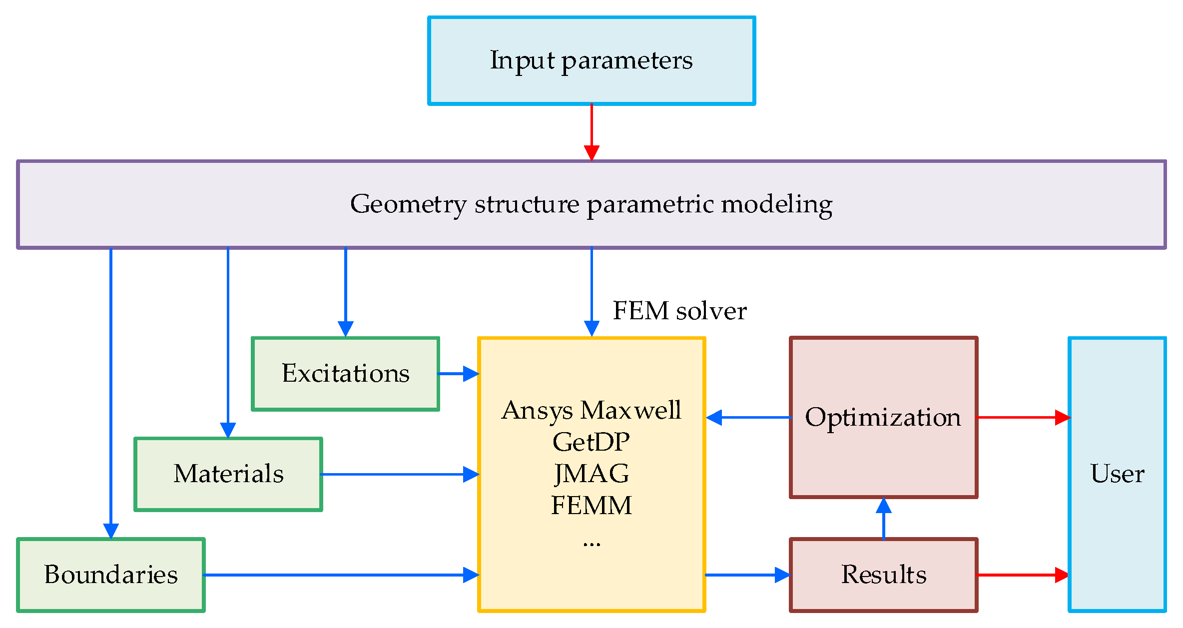
3. Universal Design Framework

The universal electric machine design framework serves as a bridge between different FEA solvers through a parametric modeling platform. Its purpose is twofold: to enable users to quickly establish parametric electric machine models for performance analysis and optimal design and to facilitate seamless transitions between different FEA software without the need to repeat the complex manual modeling process. The framework establishes a series of universal model expressions and creates an interactive interface with other software. When the software lacks built-in geometric models, the framework performs parametric modeling based on its predefined model representations. Additionally, a user-provided software model can be interpreted and converted into a format recognized by the platform. This enables the generation of parametric models for other software applications. That is to say, the framework breaks down the barriers between various software and achieves better interaction.
The framework, as shown in Figure 4, consists of input parameters, parametric modeling, an FEM solver, and post-processing components. The workflow can be summarized as follows:
  • Geometry structure parameters are input, such as slot/pole configurations, excitations, and materials. For optimization purposes, the numerical variables should have specified lower and upper limits, as well as step values. If using type variables like predefined topologies or materials, the defined number range should be provided.
  • Parametric modeling of the geometry structure, excitations, materials, and boundary settings is conducted based on the input parameters. The geometry parameters can be modified parametrically for topology optimization. The electric machine model can be automatically split into a symmetrical model to accelerate the optimization process. Excitations can be adjusted to simulate different driving cycles.
  • Calculations are performed on the electric machine model by calling the chosen FEA software (e.g., Ansys Maxwell, GetDP, JMAG, FEMM, etc.). The framework generates the corresponding FEM model based on the user’s selection. Once the FEM model is created, the framework invokes the FEA solver to perform the necessary calculations. The solver can be called in the front end or in the background to enhance parallel computing capabilities.
  • The calculation process serves various purposes, including early design performance analysis or optimization. The calculated results are immediately available for general electromagnetic performance analysis tasks. Additionally, the results can be utilized for optimization, data sampling (for surrogate models), sensitivity analysis, and other tasks according to the user’s requirements.
Overall, the universal electric machine design framework streamlines the design and analysis process, allowing for the efficient exploration and optimization of electric machine models while leveraging the capabilities of various FEA solvers.

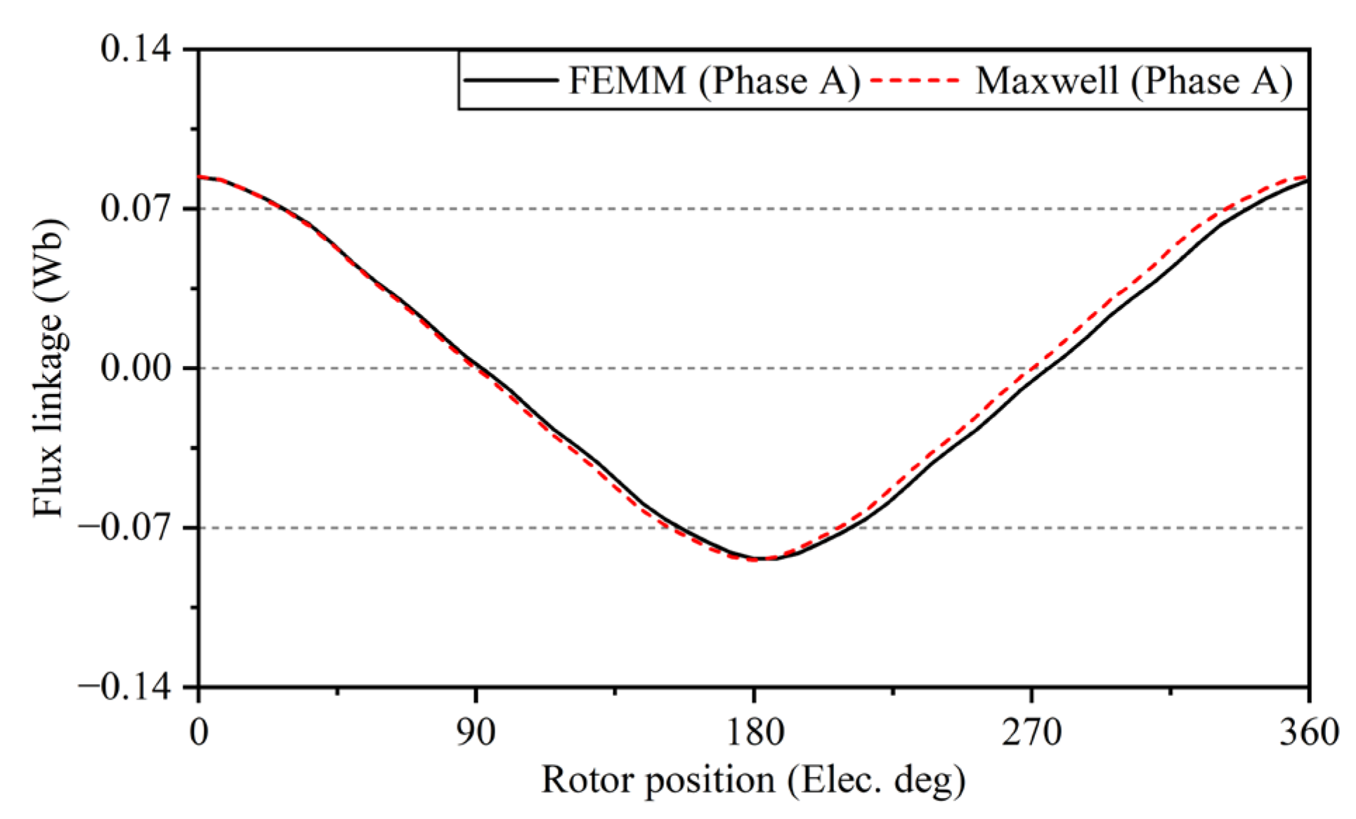
4. Numerical Validation and Discussion

In order to verify the effectiveness of the proposed universal parametric modeling framework, FEMM and Ansys Maxwell are tested based on an IPM machine, as shown in Figure 5. The FEMM model was built by the universal parametric modeling framework with the user input. Then, the model built by FEMM was transformed into a new model for Maxwell. The detailed parameters of the machine are listed in Table 2.
The parametric FEA models generated by FEMM and Ansys Maxwell were compared, and it was observed that the geometric parameters, excitation, and material settings of the two models were essentially the same. The no-load flux density distribution calculated by FEMM and Ansys Maxwell is shown in Figure 6.
The comparison focused on the no-load flux linkage, on-load torque waveform, and overload properties, as shown in Figure 7, Figure 8 and Figure 9.
In Figure 7, the no-load flux linkage calculated by the two FEA software show a very close agreement. Figure 8 displays the torque waveforms, which are not exactly the same, but the average torque values are very similar, with a relative error of 2.8%. In Figure 9, the calculated average torque values are also very similar across different current densities. These comparison results demonstrate that the different FEA models generated by the proposed parametric modeling framework can yield highly similar simulation results. This indicates that the framework is effective for parametric modeling and model transformation, making it valuable for machine design tasks.
The framework enables efficient and accurate analysis of electric machine performance, minimizing repetitive tasks and expediting the design cycle for enhanced productivity and improved outcomes, while the richness of interfaces for more FEA software can be improved in future work.

5. Conclusions

This paper presents a universal parametric modeling framework for electric machines and aims to establish an interactive interface among different FEA software. The universal parametric modeling framework defines a set of general model expressions and establishes an interactive interface with other software, which can be transformed according to the definition of other software. Moreover, a user-provided software model can be parsed and transformed into a platform-recognizable expression and then used to generate parametric models of other software. Geometric parameters are automatically adjusted to prevent interference between different parts. Additionally, the framework’s placement in the upper layer of FEA software makes it suitable for topology optimization. During the optimization process, various parameters, such as slot/pole combinations, excitations, materials, and magnetization direction, can be modified. The validity of the framework is verified through the design of electric machines using FEMM and Ansys Maxwell, with simulation results demonstrating its effectiveness.

Author Contributions

Conceptualization, W.F.; methodology, Z.Q. and W.F.; software, Z.Q. and D.J.; validation, Z.Q. and D.J.; formal analysis, Z.Q. and D.J.; writing—original draft preparation, Z.Q.; writing—review and editing, W.F. All authors have read and agreed to the published version of the manuscript.

Funding

This research was funded by the State Key Laboratory of Reliability and Intelligence of Electrical Equipment, Hebei University of Technology, grant number EERI_KF2021003.

Data Availability Statement

Not applicable.

Conflicts of Interest

The authors declare no conflict of interest.

References

  1. Donghui, C.; Wenliang, Z.; Jinghua, J.; Yanyang, W. Parametric equivalent magnetic network modeling approach for multiobjective optimization of PM machine. IEEE Trans. Ind. Electron. 2020, 68, 6619–6629. [Google Scholar]
  2. Lee, S.-H.; Hong, J.-P.; Lee, J.-Y.; Kwon, Y.K.; Jo, Y.S.; Baik, S.K.; Lee, J.D. Parametric design for superconducting synchronous motor with 3D equivalent magnetic circuit network model. IEEE Trans. Appl. Supercond. 2007, 17, 1541–1544. [Google Scholar] [CrossRef]
  3. Tikhonova, O.; Malygin, I.; Plastun, A. Electromagnetic calculation for induction motors of various designs by ANSYS maxwell. In Proceedings of the 2017 International Conference on Industrial Engineering, Applications and Manufacturing (ICIEAM), St. Petersburg, Russia, 16–19 May 2017. [Google Scholar]
  4. Oh, S.-Y.; Hwang, K.-Y.; Song, B.-K.; Kim, S.-I. Motor parametric design using an electro-hydraulic model of a brake system. IEEE Access 2022, 10, 61375–61384. [Google Scholar] [CrossRef]
  5. Wei, L.; Yongling, H. Parameterization and performance of permanent magnet synchronous motor for vehicle based on Motor-CAD and optiSLang. Wirel. Commun. Mob. Comput. 2022, 2022, 8217386. [Google Scholar]
  6. Xing, F.; Zhao, W.; Kwon, B.-I. Design and optimisation of a novel asymmetric rotor structure for a PM-assisted synchronous reluctance machine. IET Electr. Power Appl. 2019, 13, 573–580. [Google Scholar] [CrossRef]
  7. Malagoli, J.A.; Camacho, J.R.; da Luz, M.V.F. Optimal electromagnetic torque of the induction motor generated automatically with Gmsh/GetDP software. Int. Trans. Electr. Energy Syst. 2021, 31, e12773. [Google Scholar] [CrossRef]
  8. Baluta, G.; Graur, A.; Pentiuc, R.; Diaconescu, C.; Popa, C. FEM analysis of brushless DC servomotor with fractional number of slots per pole. Adv. Electr. Comput. Eng. 2014, 14, 103–108. [Google Scholar] [CrossRef]
  9. Iyer, L.V.; Lai, C.; Dhulipati, H.; Mukundan, S.; Mukherjee, K.; Kar, N.C. A novel MTPA theory based bottom-up approach towards parametric and structural design of interior PMSM for electric vehicles. Int. Trans. Electr. Energy Syst. 2018, 28, e2489. [Google Scholar] [CrossRef]
  10. Fu, W.; Chen, Y. Data structures and program techniques of finite element methods for analysis and optimization of electric devices. Int. J. Appl. Electromagn. Mech. 2015, 47, 875–883. [Google Scholar] [CrossRef]
  11. Bianchi, N.; Dai Pre, M. Use of the star of slots in designing fractional-slot single-layer synchronous motors. IEE Proc.-Electr. Power Appl. 2006, 153, 459–466. [Google Scholar] [CrossRef]
  12. Caruso, M.; Di Tommaso, A.O.; Marignetti, F.; Miceli, R.; Ricco Galluzzo, G. A general mathematical formulation for winding layout arrangement of electrical machines. Energies 2018, 11, 446. [Google Scholar] [CrossRef] [Green Version]
  13. Ramesh, P.; Lenin, N.C. High power density electrical machines for electric vehicles—Comprehensive review based on material technology. IEEE Trans. Magn. 2019, 55, 0900121. [Google Scholar] [CrossRef]
  14. Bramerdorfer, G.; Goldbeck, G.; Kitzberger, M. On the accuracy and improvement of FE-based electric machine evaluation concerning soft magnetic material modeling. In Proceedings of the 2019 IEEE Energy Conversion Congress and Exposition (ECCE), Baltimore, MD, USA, 29 September–3 October 2019. [Google Scholar]
  15. Li, H.L.; Ho, S.L.; Fu, W.N. Precise magnetic field modeling techniques of rotary machines using transient finite-element method. IEEE Trans. Magn. 2012, 48, 4192–4195. [Google Scholar] [CrossRef]
  16. Nicolae, P.-M.; Bida, E.-F. Aspects regarding the simulation of an electric drive pm motor used in light electric vehicles. In Proceedings of the 2016 International Conference on Applied and Theoretical Electricity (ICATE), Craiova, Romania, 6–8 October 2016. [Google Scholar]
  17. Nugraha, Y.U.; Yuniarto, M.N.; Herizal, H.; Asfani, D.A.; Riawan, D.C.; Wahyudi, M. Design analysis of axial flux permanent magnet BLDC motor 5 kW for electric scooter application. In Proceedings of the 2018 International Seminar on Intelligent Technology and Its Applications (ISITIA), Bali, Indonesia, 30–31 August 2018. [Google Scholar]
  18. Sadrossadat, S.A.; Rahmani, O. ANN-based method for parametric modelling and optimising efficiency, output power and material cost of BLDC motor. IET Electr. Power Appl. 2020, 14, 951–960. [Google Scholar] [CrossRef]
  19. Raia, M.R.; Ciceo, S.; Chauvicourt, F.; Martis, C. Multi-attribute machine learning model for electrical motors performance prediction. Appl. Sci. 2023, 13, 1395. [Google Scholar] [CrossRef]
  20. You, Y.-M. Multi-objective optimal design of permanent magnet synchronous motor for electric vehicle based on deep learning. Appl. Sci. 2020, 10, 482. [Google Scholar] [CrossRef] [Green Version]
  21. Sato, T.; Fujita, M. A data-driven automatic design method for electric machines based on reinforcement learning and evolutionary optimization. IEEE Access 2021, 9, 71284–71294. [Google Scholar] [CrossRef]
  22. Poudel, B.; Amiri, E. Deep learning based design methodology for electric machines: Data acquisition, training and optimization. IEEE Access 2023, 11, 18281–18290. [Google Scholar] [CrossRef]
Figure 1. The arrangement of a 12-slot IPM machine with single-layer winding. (a) 12-slot, 2-pole, distributed winding with coil pitch = 5; (b) 12-slot, 2-pole, distributed winding with coil pitch = 3; (c) 12-slot, 10-pole, concentrated winding with coil pitch = 1.
Energies 16 05897 g001
Figure 2. Benchmark of the stator.
Energies 16 05897 g002
Figure 3. Benchmark of the rotor.
Energies 16 05897 g003
Figure 4. Universal electric machine design framework.
Energies 16 05897 g004
Figure 5. IPM machine model built by FEMM (left) and Ansys Maxwell (right).
Energies 16 05897 g005
Figure 6. No-load flux density distribution calculated by FEMM (left) and Ansys Maxwell (right).
Energies 16 05897 g006
Figure 7. Comparison of no-load flux linkage between FEMM and Maxwell.
Energies 16 05897 g007
Figure 8. Comparison of rated torque waveform between FEMM and Maxwell.
Energies 16 05897 g008
Figure 9. Comparison of overload property between FEMM and Maxwell.
Energies 16 05897 g009
Table 1. The current flow direction of a 12-slot IPM machine with single-layer winding.
Coil PitchPhase APhase BPhase C
5(1, −6) (12, −7)(4, −11) (5, −10)(8, −3) (9, −2)
3(1, −4) (10, −7)(2, −11) (5, −8)(6, −3) (9, −12)
1(1, −2) (8, −7)(4, −3) (9, −10)(5, −6) (12, −11)
Table 2. Parameters of the IPM machine.
ParametersPhase AUnit
Number of stator slots48-
Number of rotor poles8-
Rotation speed3000r/min
Stack length83.82mm
Stator outer diameter198mm
Stator inner diameter132mm
Stator slot top width6.6mm
Stator slot top corner radius1.5mm
Stator slot depth17.5mm
Stator slot bottom width4.3mm
Stator slot wedge depth0.3mm
Stator tooth tip depth1mm
Stator slot opening3mm
Air gap length1mm
Rotor outer diameter65mm
Rotor bridge thickness2mm
Rotor pole shoe opening angle36.76deg.
Rotor magnet pole V angle125deg.
Rotor magnet pole inner interval width2mm
Rotor magnet pole outer interval width2mm
Rotor magnet offset length3mm
Magnet width 14mm
Magnet thickness3.5mm
Shaft diameter80mm
Magnet materialN40SH-
Iron materialM400-50A-
Number of coil turns8-
Slot filling0.6-
Current density6A/mm2
Disclaimer/Publisher’s Note: The statements, opinions and data contained in all publications are solely those of the individual author(s) and contributor(s) and not of MDPI and/or the editor(s). MDPI and/or the editor(s) disclaim responsibility for any injury to people or property resulting from any ideas, methods, instructions or products referred to in the content.

