Article

Experimental Study on Wind Turbine Airfoil Trailing Edge Noise Reduction Using Wavy Leading Edges

1
School of Power and Energy, Northwestern Polytechnical University, Xi’an 710129, China
2
Key Laboratory of Aerodynamic Noise Control, China Aerodynamics Research and Development Center, Mianyang 621000, China
3
Collaborative Innovation Center for Advanced Aero-Engine, Beijing 100191, China
*
Author to whom correspondence should be addressed.
Energies 2023, 16(16), 5865; https://doi.org/10.3390/en16165865
Submission received: 16 June 2023 / Revised: 24 July 2023 / Accepted: 4 August 2023 / Published: 8 August 2023
(This article belongs to the Special Issue Advanced Research and Methods of Noise Control for Wind Turbine)

Abstract

:
Aerodynamic noise produced by the rotating blade is an important hindrance for the rapid development of modern wind turbines. Among the various noise sources, the airfoil trailing edge noise contributes a lot to the wind turbine noise. The control of wind turbine airfoil trailing edge self-noise by bio-inspired sinusoidal wavy leading edges is experimentally studied in a semi-anechoic chamber. The noise radiated by the baseline NACA 0012 airfoil and various wavy airfoils is measured using a planar microphone array consisting of fifty-two microphones. The noise source identifications are achieved by using the CLEAN-SC method. The effects of velocity and angle of attack on noise radiation of the baseline airfoil are analyzed in detail. The noise control law of the wavy amplitude and wavelength on airfoil trailing edge noise is explored. Based on the acoustic beamforming results, the noise control effects of the wavy leading edges are intuitively demonstrated. In general, the wavy leading edge with a larger amplitude and smaller wavelength has a better effect on the airfoil trailing edge noise reduction. The maximum sound pressure level reduction can be up to 33.9 dB. The results of this study are expected to provide important information for wind turbine aerodynamic noise control.

1. Introduction

With the rapid consumption and increasing scarcity of traditional fossil energy, people are gradually turning their attention to the efficient development and utilization of renewable energy [1]. Wind energy is one of the popular sources of power due to its accessibility, clean and low-carbon nature, abundant reserves and other characteristics. The latest Global Wind Report 2023 was released by the GWEC (Global Wind Energy Council) in São Paulo, Brazil. The report predicts that by 2024, the capacity of newly installed global onshore wind power will surpass over 100 GW for the first time, and by 2025, the newly installed capacity of global offshore wind power will also hit a new high, reaching 25 GW. In the next five years, the newly added grid-connected capacity of wind power in the world will reach 680 GW [2].
Although wind energy can be developed and utilized on a large scale, it will also have a certain impact on the surrounding environment [3]. Similar to aviation noise [4], the noise generated by wind turbine blades will have a certain impact on the physical and mental health of local residents [5,6] and bird migration activities or animals’ reproductive activities [7,8]. With the rapid development and application of wind turbines, the power generation of a single wind turbine has increased, and the size of the wind turbine has also become larger and larger. With the increase in rotor diameter and blade tip speed, the problem of noise pollution generated in the working process of the wind turbines is becoming increasingly serious. The wind turbine noise has caused more and more complaints from nearby residents. The wind turbine noise is a problem that must be addressed for further development of advanced wind turbine technologies [9].
The airfoil trailing edge noise generated by the interaction of the boundary layer turbulence with the airfoil trailing edge is the main noise source of wind turbines [10]. Brooks et al. divided the generation mechanism of airfoil self-noise into five types based on the different flow patterns of the airfoil boundary layer [11]. Due to the broadband nature of wind turbine noise, its noise control is a challenging task. High power and low noise pollution are the development direction of wind turbines in the future. To make wind power generation truly clean, it is urgent to conduct systematic research and develop advanced noise control methods for wind turbines.
Lutz et al. proposed a method to predict airfoil trailing edge noise and used it in acoustic airfoil design. They developed three different airfoils for the outer blade regions of three MW-class reference wind turbines, which can reduce the overall sound pressure level by 1–3.5 dB without loss of performance [12]. Sanghyeon et al. used a hybrid computational aero-acoustics method to study the aerodynamic noise characteristics of Savonius wind turbines and proposed a low-noise design based on their understanding of the noise generation mechanism. The study found that the adoption of S-shaped trailing edge blades reduced the noise level of the Savonius wind turbine by 2.7 dB [13].
Avallone et al. modified the trailing edge of the NACA 0018 airfoil to reduce the trailing edge noise caused by the turbulent boundary layer. It is proved by calculation and experimental validation that the combed-sawtooth serrations can achieve a better noise reduction effect than the traditional sawtooth serration in the low to middle frequency range [14]. In general, the use of trailing edge serrations always leads to a reduced aerodynamic performance. In order to solve this issue, Zhao et al. have developed a new type of serrated airfoil that can maintain high aerodynamic performance [15]. Showkat et al. studied porous treatment as one of the means of aerodynamic noise reduction. The influence of the interaction between flow and porous material is studied, and the noise reduction mechanism of porous material is explored [16].
In 1995, Fish et al. first published a study on the hydrodynamic performance of the tubercle structure of the pectoral flippers of humpback whales in the Journal of Morphology [17]. Subsequently, a large number of researchers have conducted research on the impact of wavy leading edge structures on the aerodynamic performance and aerodynamic noise of airfoils and blades.
In 2010, Hansen et al. [18] first studied the control effect of wavy leading edges on tone noise of the NACA 0012 airfoil. It was found that the wavy leading edges can significantly reduce the tonal noise of the NACA 0012 airfoil at a Reynolds number of approximately 120,000. Hansen also pointed out that the noise reduction mechanism of the wavy leading edges is the formation of streamwise vortices caused by tubercles, which can enhance the momentum exchange in the downstream boundary layer, improve the stability of the boundary layer, and destroy the acoustic feedback mechanism. Gruber et al. [19] studied tandem airfoils using two types of serrated trailing edges for the upstream airfoil and a wavy leading edge for the downstream airfoil. They investigated the effect of wavy leading edges on wake–airfoil interference noise, reaching a broadband interference noise reduction of 5–8.5 dB.
Feinerman et al. [20] studied the effect of sinusoidal wavy leading edges on helicopter blade–vortex interference noise. The experiment showed that the wavy leading edge can reduce interference noise by up to 3 dB and proposed that the noise reduction mechanism lies in destructive phase interference. Chen et al. [21] conducted an experimental study on the influence of wavy leading edges on the interference noise of the NACA 0012 airfoil and parameterized the amplitude and wavelength characteristics of the wavy leading edges. Research has found that the noise reduction effect is sensitive to the amplitude and wavelength of the wavy leading edges. The wavy leading edge with maximum amplitude and minimum wavelength can achieve the most significant noise reduction effect, up to 4 dB.
Most studies use trailing edge serrations to control airfoil trailing edge noise [22], while wavy leading edges inspired by humpback whale flippers are often used to control leading edge airfoil–turbulence interaction noise [23,24,25]. However, few studies have addressed the effect of a wavy leading edge on airfoil trailing edge noise [26]. Lacagnina et al. [27] studied the effect of leading edge serrations on reducing the self-noise of airfoils over a large angle of attack range. The results indicate that at most angles of attack, the leading edge serrations can reduce the self-noise of the airfoil, but have a negative impact on the aerodynamic performance. Kim et al. [28] also studied the NACA 65(12)-10 airfoil with sinusoidal leading edge fluctuations. Under the condition of an effective Reynolds number of 106, the aerodynamic and acoustic performance of the airfoil was optimized simultaneously by considering the attachment and separation flow. The maximum lift of the airfoil is improved without sacrificing the overall noise and the drag at near/post stall angles of attack. Taking into account both aerodynamic performance and noise level, an optimal leading edge fluctuation structure was proposed. The purpose of this study is to reduce the airfoil trailing edge noise at small angles of attack and a wide speed range using the wavy leading edges, and to explore the noise reduction law of the wavy leading edges with different amplitudes and wavelengths.

2. Experimental Set-Up and Procedures

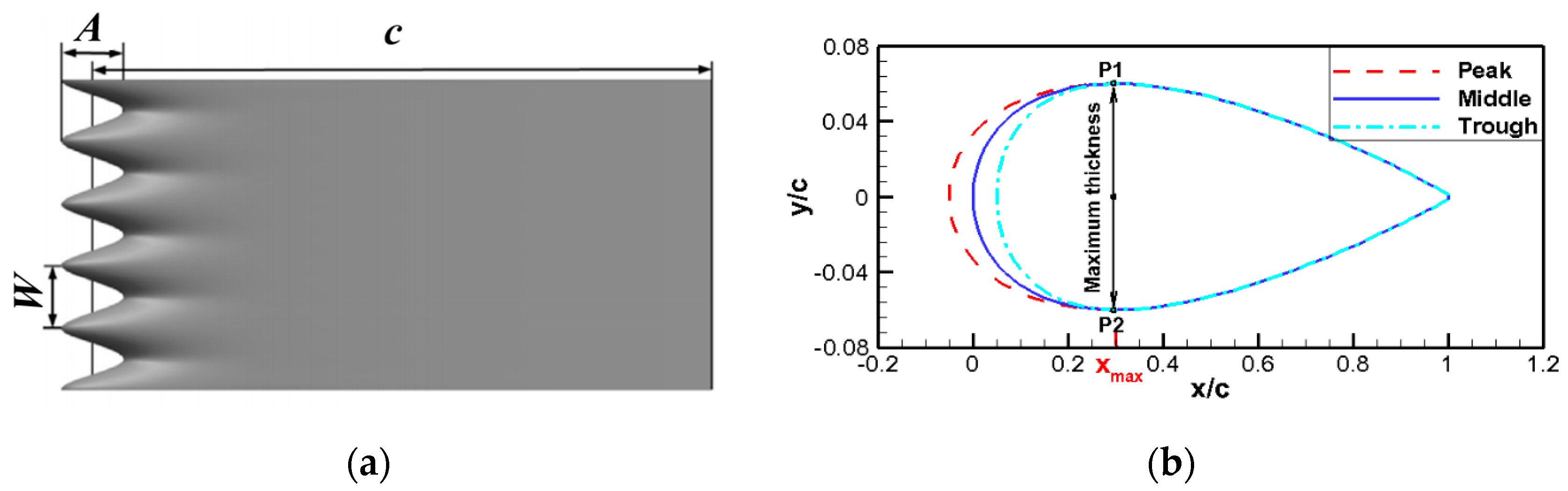
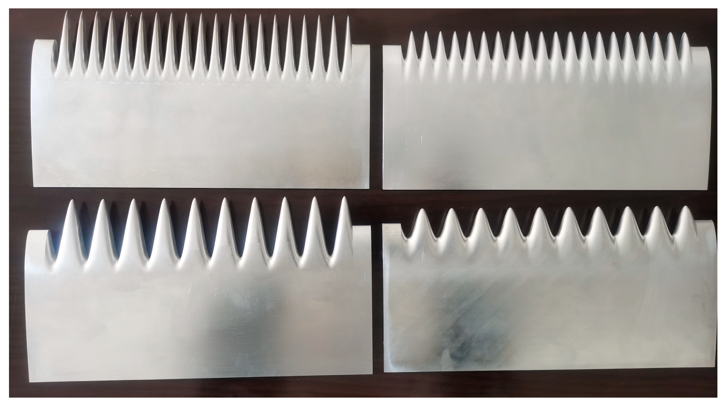
2.1. Design of Wavy Leading Edges

In this study, the NACA 0012 airfoil with a chord length of 100 mm and a span length of 225 mm was used as the baseline airfoil. Seven sinusoidal wavy leading edge airfoils with different amplitudes (A) and wavelengths (W) were studied. The detailed design parameters are shown in Table 1. All wavy airfoils are marked by a combination of dimensionless percentages of amplitude and wavelength based on chord length. As shown in Figure 1b, the local chord length is changed only by stretching and compressing the geometry from the leading edge to the position of maximum thickness, keeping the averaged chord length and projected area of the wavy leading edge airfoils consistent with the baseline airfoil. The variation of the chord length of the wavy leading airfoils along the spanwise direction is defined by Equation (1), and the span section is generated by Equation (2).
c ( z ) = c + A 2 cos ( 2 π W z )
{ x n e w = { x o l d x max [ x max + ( c ( z ) c ) ] [ c ( z ) c ] x o l d < x max x o l d x o l d x max y n e w = y o l d
The subscript ‘new’ represents the wavy leading edge airfoil and ‘old’ represents the baseline airfoil. x max represents the maximum thickness position of the baseline airfoil.
The 8 airfoils studied in this paper are all made of aluminum processed by computer numerical control (CNC) machine tools, and the physical objects are shown in Figure 2. In order to ensure that the spanwise direction includes integer multiples of the wavelengths, and to facilitate the detachable installation, 12.5 mm was reserved at both ends of the airfoil, which means the actual span length including the wavy leading edges is 200 mm.

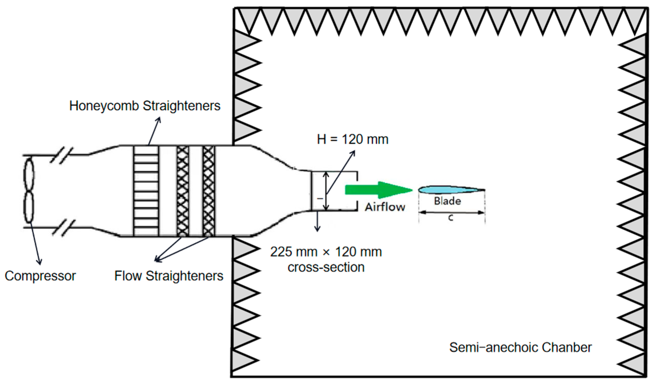
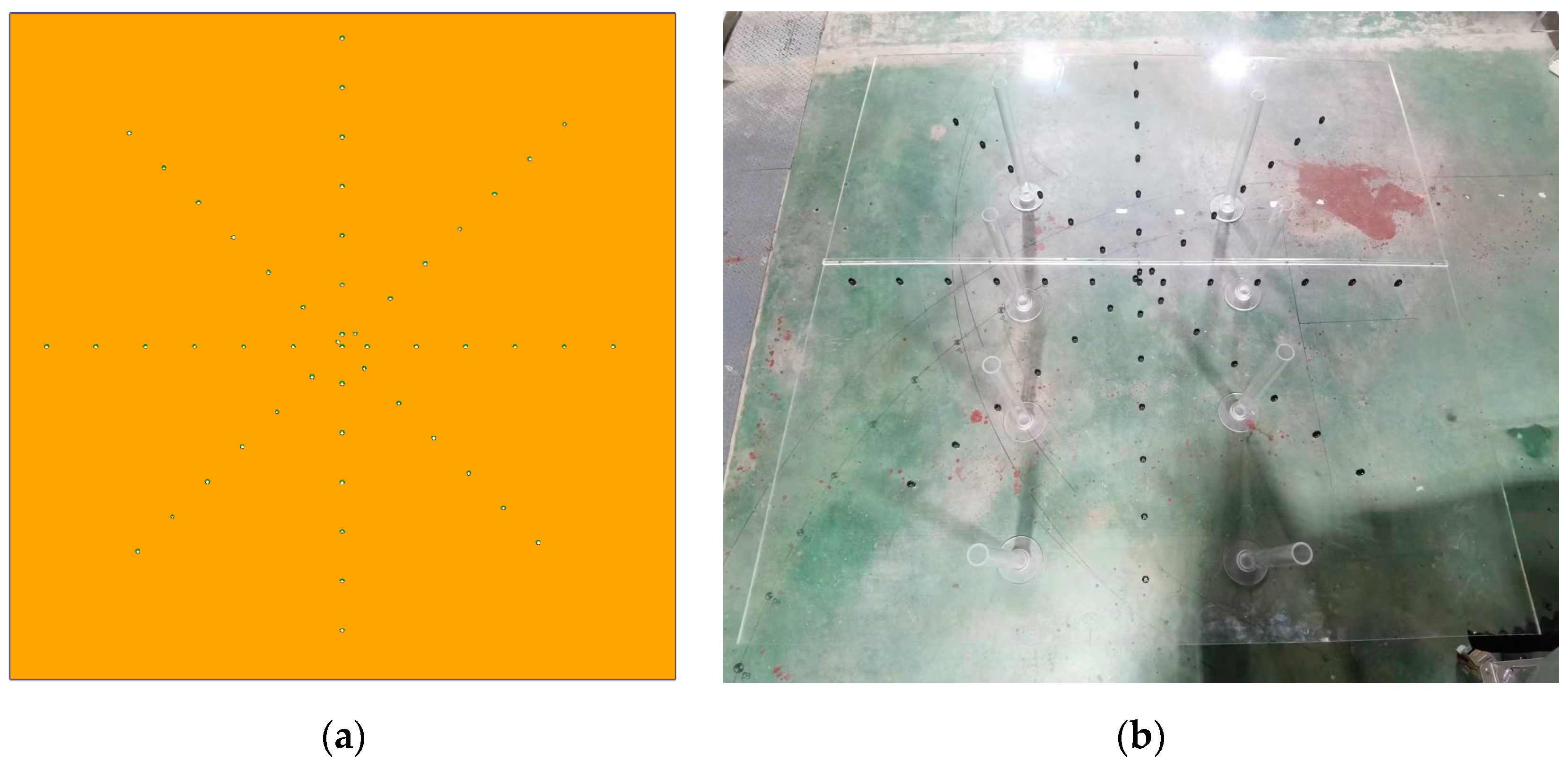
2.2. Test Facility and Instrumentation

This study was carried out in the semi-anechoic chamber of Turbomachinery Aerodynamics and Aeroacoustics Laboratory (TAAL) of Northwestern Polytechnical University, as shown in Figure 3. The outlet size of the wind tunnel is 225 × 120 mm, with a maximum incoming flow velocity of 100 m/s, and a turbulence intensity of approximately 1%. The test airfoil is installed by two parallel organic glass plates at a distance of 50 mm away from the nozzle outlet, as shown in Figure 4.
Based on the size and basic rotation speed of modern wind turbines, we chose an experimental incoming flow velocity range of 20 to 70 m/s with a speed interval of 10 m/s. And the range of variable geometric angle of attack is set to be ±15° with an interval of 5°. Since the airfoil is installed in an open-jet wind tunnel, it can cause downwash of incoming flow, resulting in a decrease in the effective angle of attack. Based on the theory of equal lift surfaces, Brooks et al. [29] proposed a revised formula for the two-dimensional open-jet wind tunnel. The corrected angle of attack is equivalent to the angle of attack corresponding to the same lift generated under free flow conditions.
α = α t / ζ
in which,
ζ = ( 1 + 2 σ ) 2 + 12 σ
σ = ( π 2 / 48 ) ( c / H ) 2
Among them, α t is the geometric angle of attack, α is the effective angle of attack, c is the chord length of the airfoil, and for horizontally installed airfoils, H is the exit height of the wind tunnel. In this study, H = 120 mm. Using the above formula to correct the angle of attack, the corrected actual effective angle of attack range is calculated to be ±5°. The geometric angle of attack of 10° corresponds to an effective angle of attack of 3.4°.
As shown in Figure 4, a helical planar microphone array consisting of 52 BSWA MPA401 1/4-inch microphones is placed at a distance of 450 mm from the airfoil trailing edge, and the sound source is identified using the CLEAN-SC method [30,31]. Among them, the #1 microphone (at the center of the microphone array panel) is located directly below the midpoint of the airfoil trailing edge. The geometric model and the practical photograph of the microphone array panel are shown in Figure 5.
The sound pressure level (SPL) is defined by Equation (6), where Spp is the power spectral density of the sound pressure, and Pref is the reference sound pressure. The sampling frequency of this experiment is 32,768 Hz, and the sampling time of each group of acoustic signals is 20 s. Welch’s method [32] is used to calculate the sound pressure power spectral density. The number of Fourier transform points is 1024, the data overlap rate is 50%, and the window function is Hamming window. The spectral resolution is 32 Hz and the number of averaging is 1279.
SPL ( f ) = 10 log 10 ( S p p ( f ) / p r e f 2 )

3. Results and Discussions

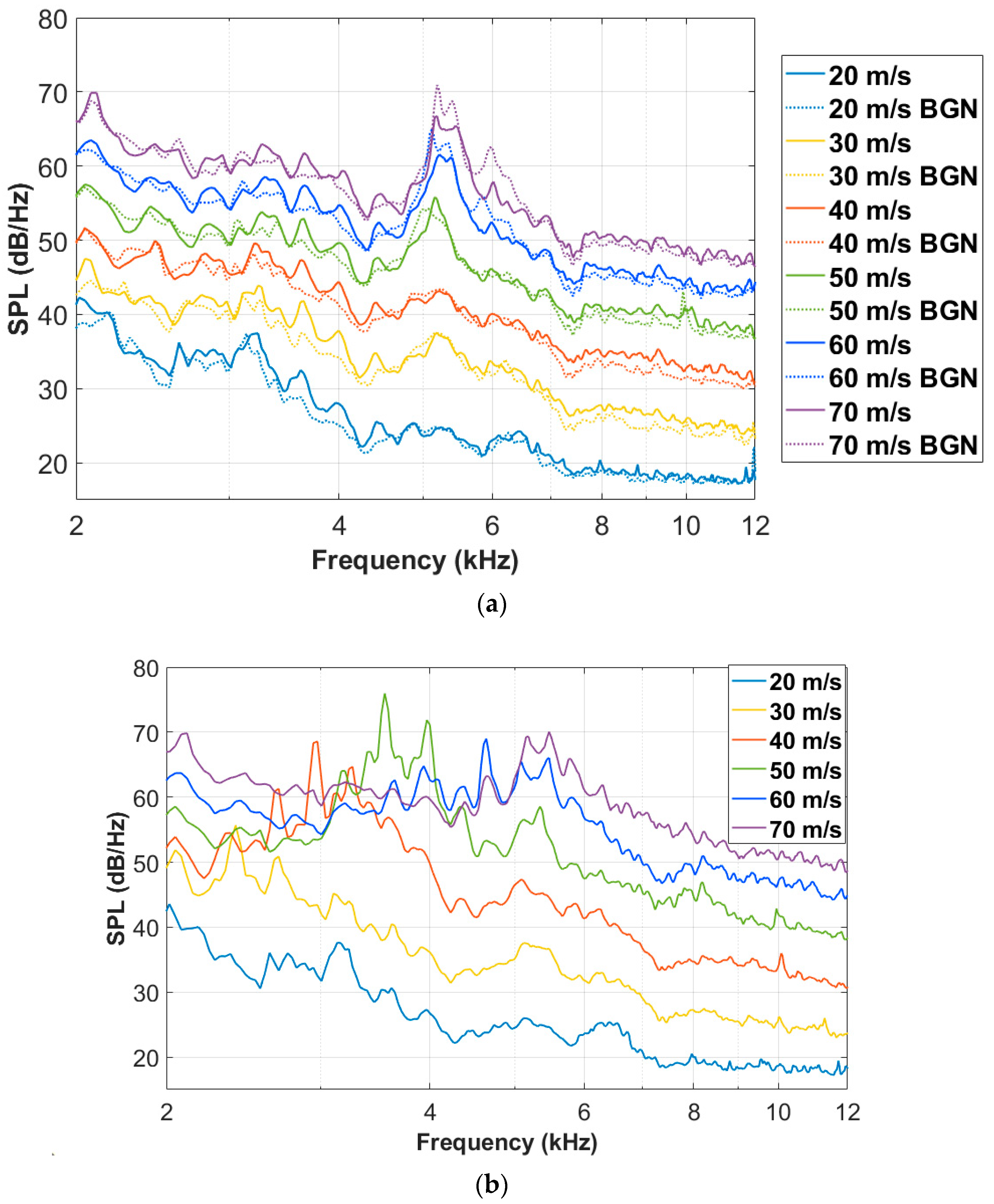
3.1. Noise Radiations of the Baseline Airfoil

Firstly, the effects of incoming flow velocity and angle of attack on the noise radiation of the baseline airfoil are studied. As shown in Figure 6, the noise spectra of the baseline airfoil measured by microphone #1 at different speeds at 0° and 10° geometric angles of attack are compared. Since the background noise is the dominant noise source below 2 kHz, this paper only discusses the noise radiation characteristics within the range of 2 kHz to 10 kHz. It can be seen from the figure that the broadband noise radiated by the airfoil generally increases with the increase in the incoming flow velocity. At the same time, as shown in Figure 6b, the frequency of the noise hump also gradually increases with the increase in the incoming flow velocity, and the noise peak will first increase and then decrease with the increase in velocity. Figure 6a also shows the spectrum of background noise (BGN) at different speeds. The solid line represents the case where there is a baseline airfoil without angle of attack, while the dashed line represents the case where there is no airfoil, only the wind tunnel and acrylic plates used to fix the airfoils. It can be seen that the broadband noise level of the background is generally lower than when there is a baseline airfoil. However, the background noise can be even higher, near 5200 Hz, which may be due to the influence of the airfoil on the vortex shedding at the trailing edge of the acrylic plates.
Figure 7 shows the comparison of the noise radiation of the baseline airfoil at different geometric angles of attack when the incoming flow velocities are 40, 50 and 60 m/s. The law that the noise radiation level increases with the increase in the attack angle can be obtained from these pictures at different speeds. The difference is the frequency range of hump noise, which varies with speed as discussed earlier. It can be seen from Figure 7b that, when the incoming flow velocity is 50 m/s, the sound pressure level of the hump noise at 2600–4500 Hz and the broadband noise at 6000–9000 Hz both increase with the increase in the angle of attack. It should be noted that the noise hump near 5200 Hz is actually the background noise caused by the organic glass plates used to fix the airfoils, which is not considered here. In the frequency range of 2600–4500 Hz, the hump noise of the baseline airfoil increases from 53 dB at 0° angle of attack to 59 dB at 5° angle of attack, while at 10° angle of attack, the maximum sound pressure level can reach up to 76 dB.
Figure 8 shows the sound source identification results of the baseline airfoil at different one-third octave center frequencies when the incoming flow velocity is 50 m/s, and the angles of attack are 0° and 10°, respectively. The dashed lines and solid boxes in the figures indicate the relative positions of the wind tunnel outlet and the airfoil, respectively. It can be seen from the figure that when the angle of attack changes from 0° to 10°, the main sound sources that cause the noise increase at 4 kHz and 8 kHz are all at the trailing edge of the airfoil. To minimize the impact of background noise, the noise spectrum within the dashed square box region shown in Figure 8d is averaged to obtain trailing edge noise for the following analysis.

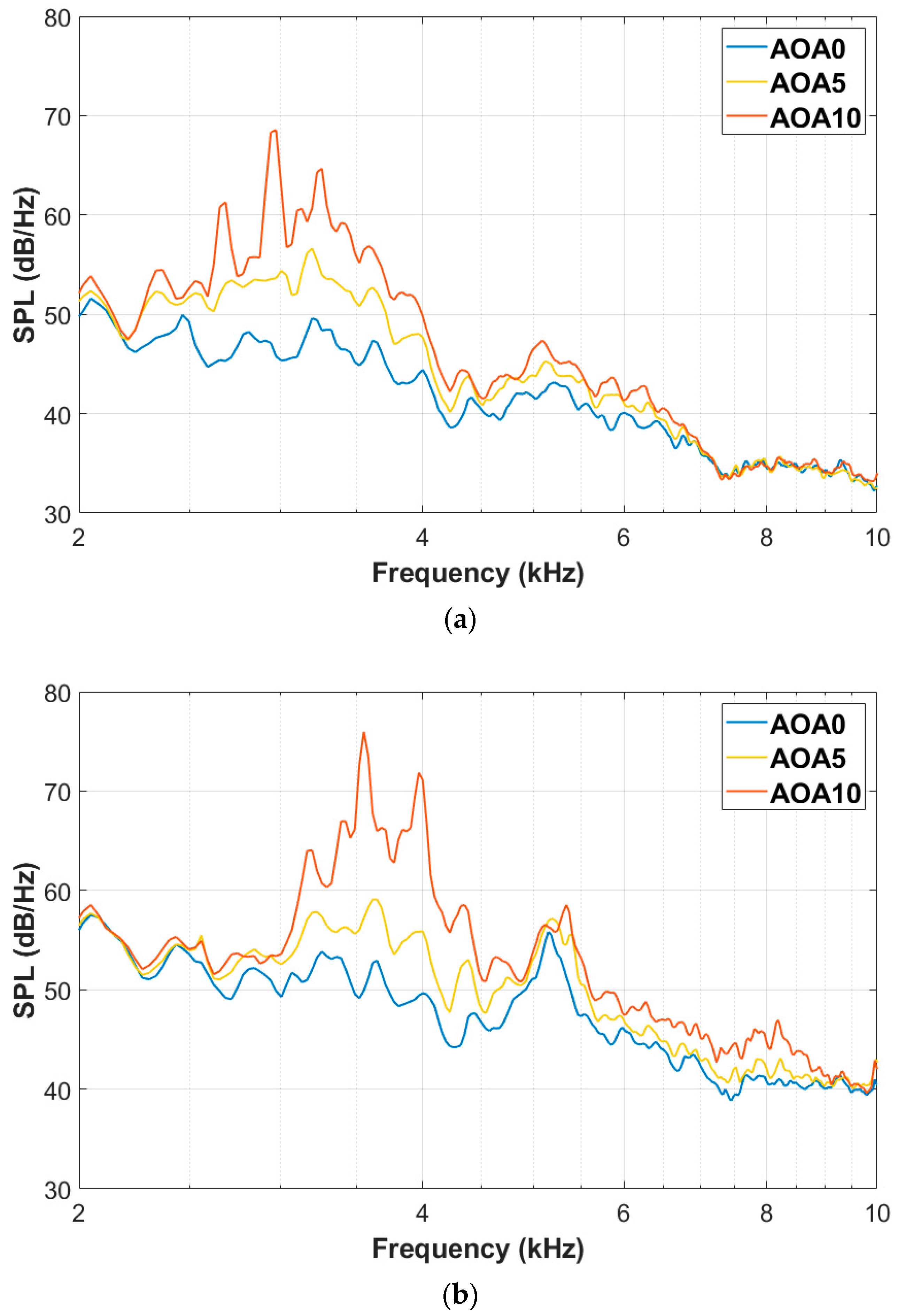
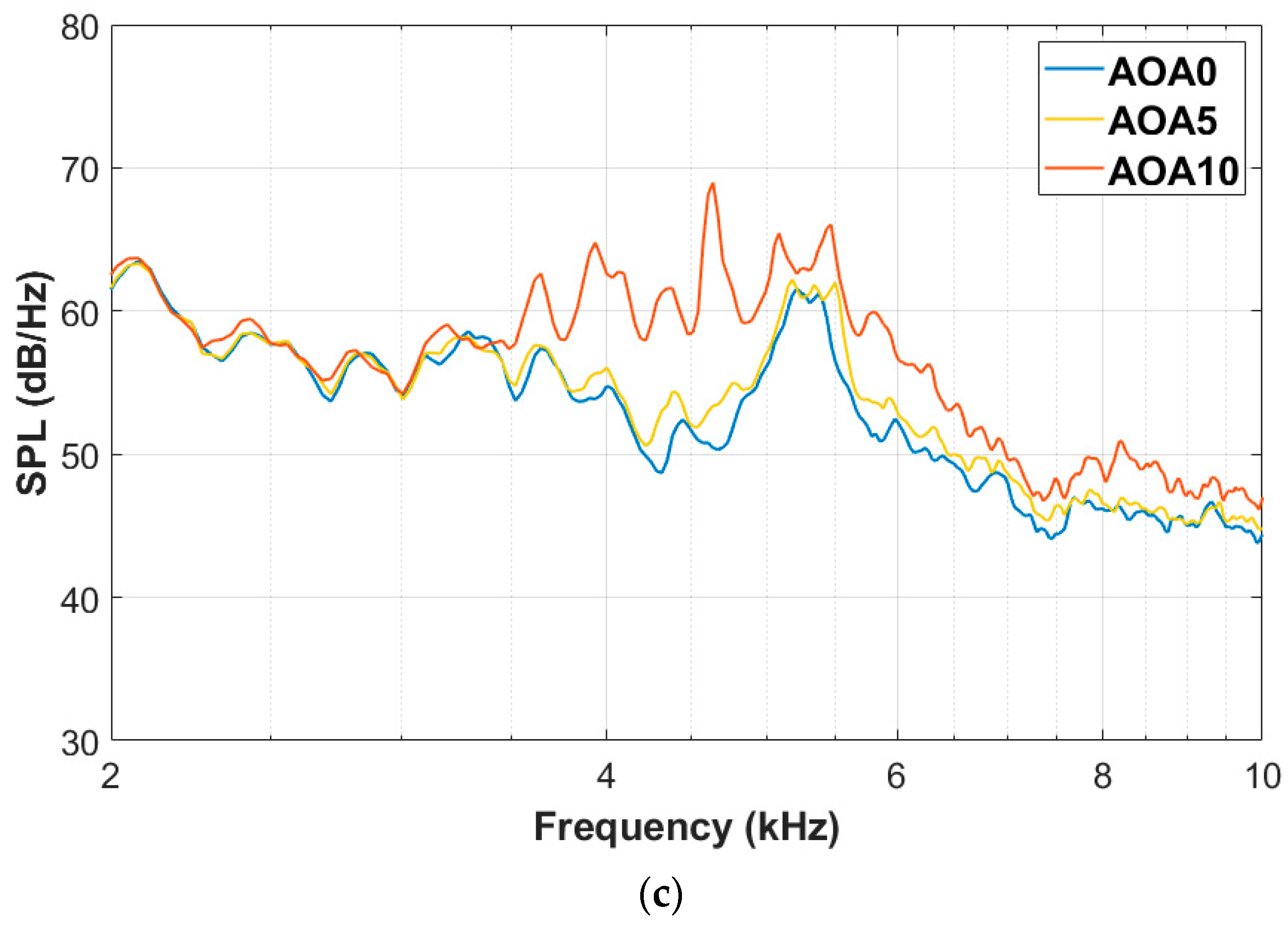
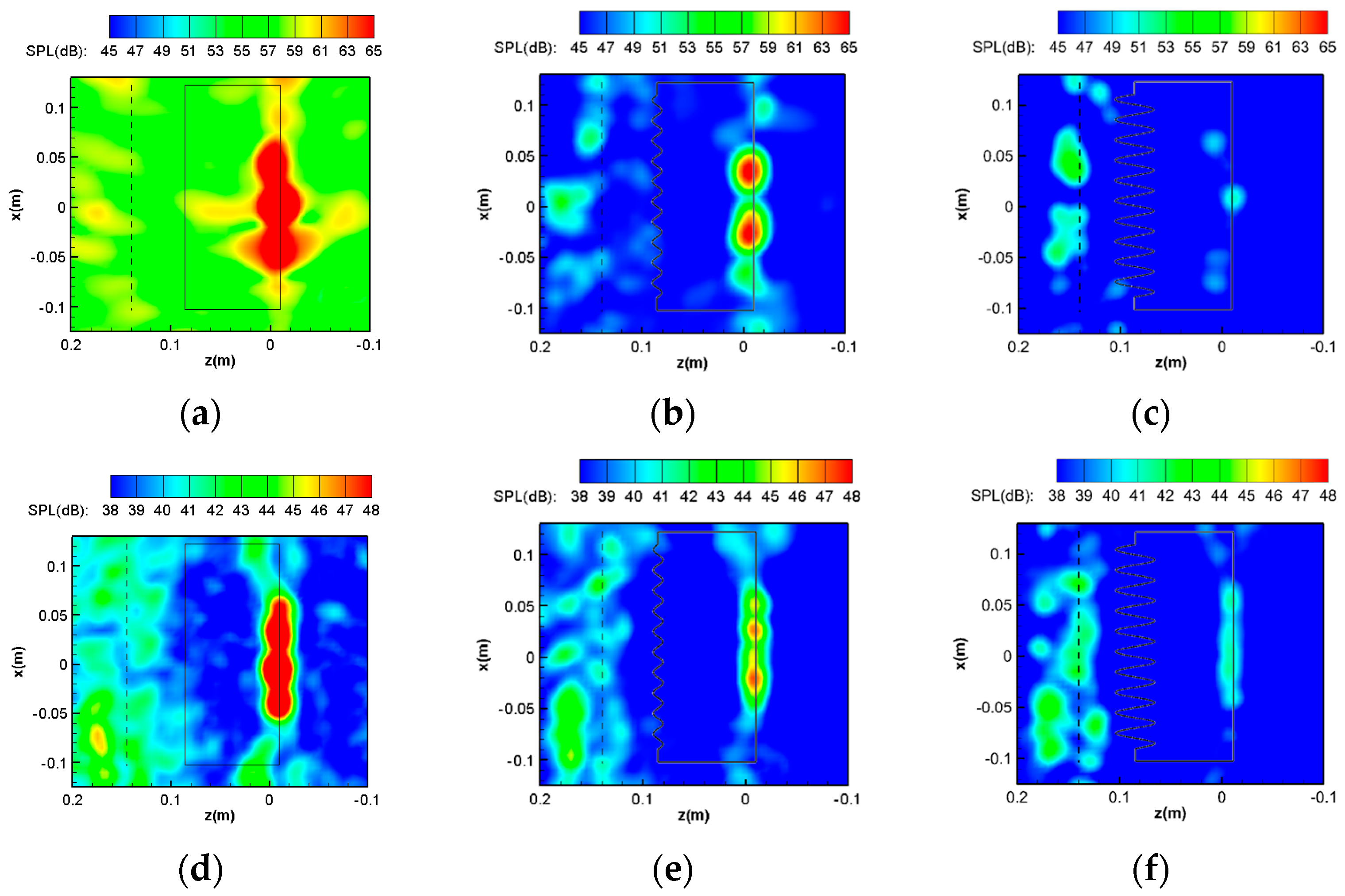
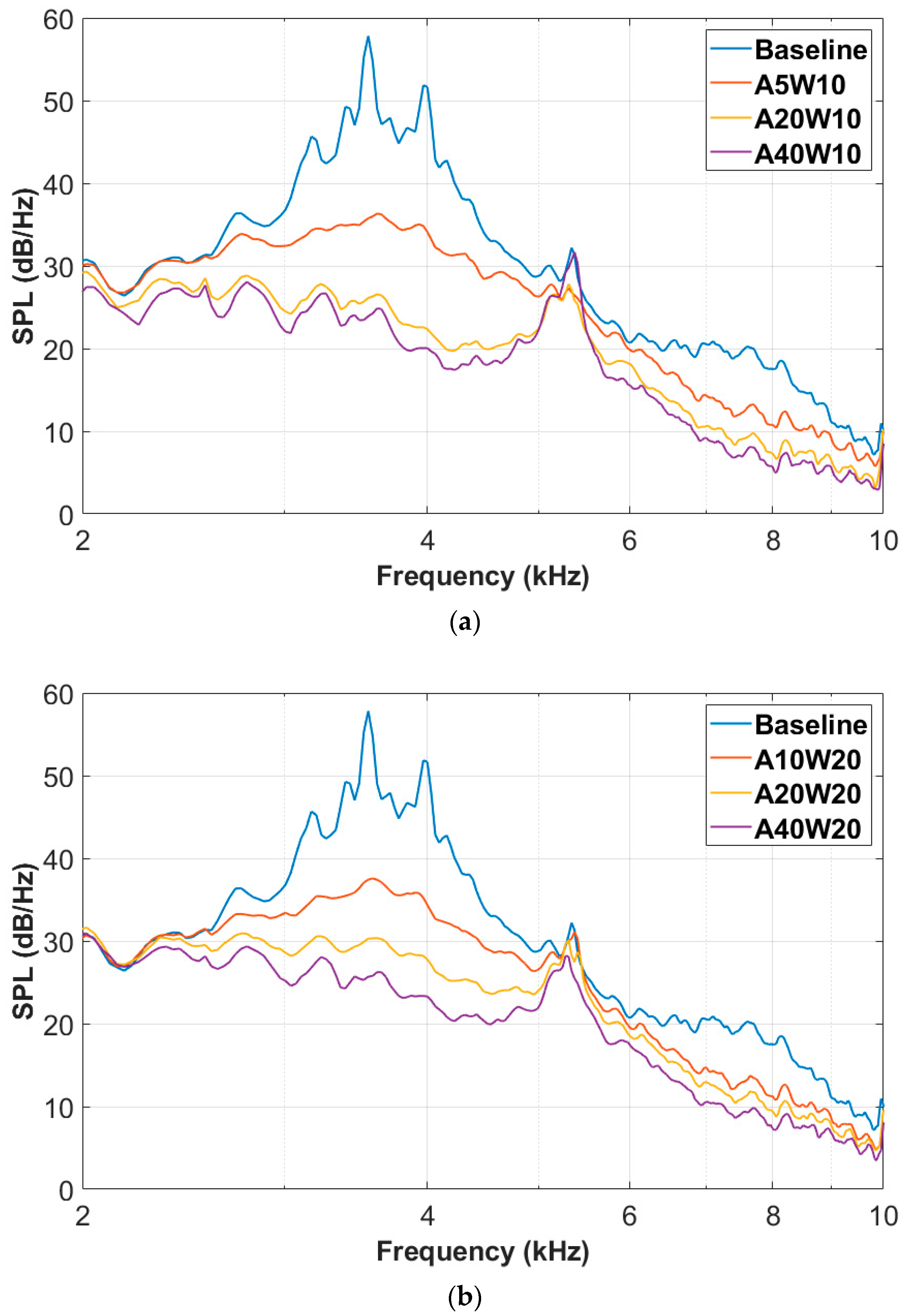
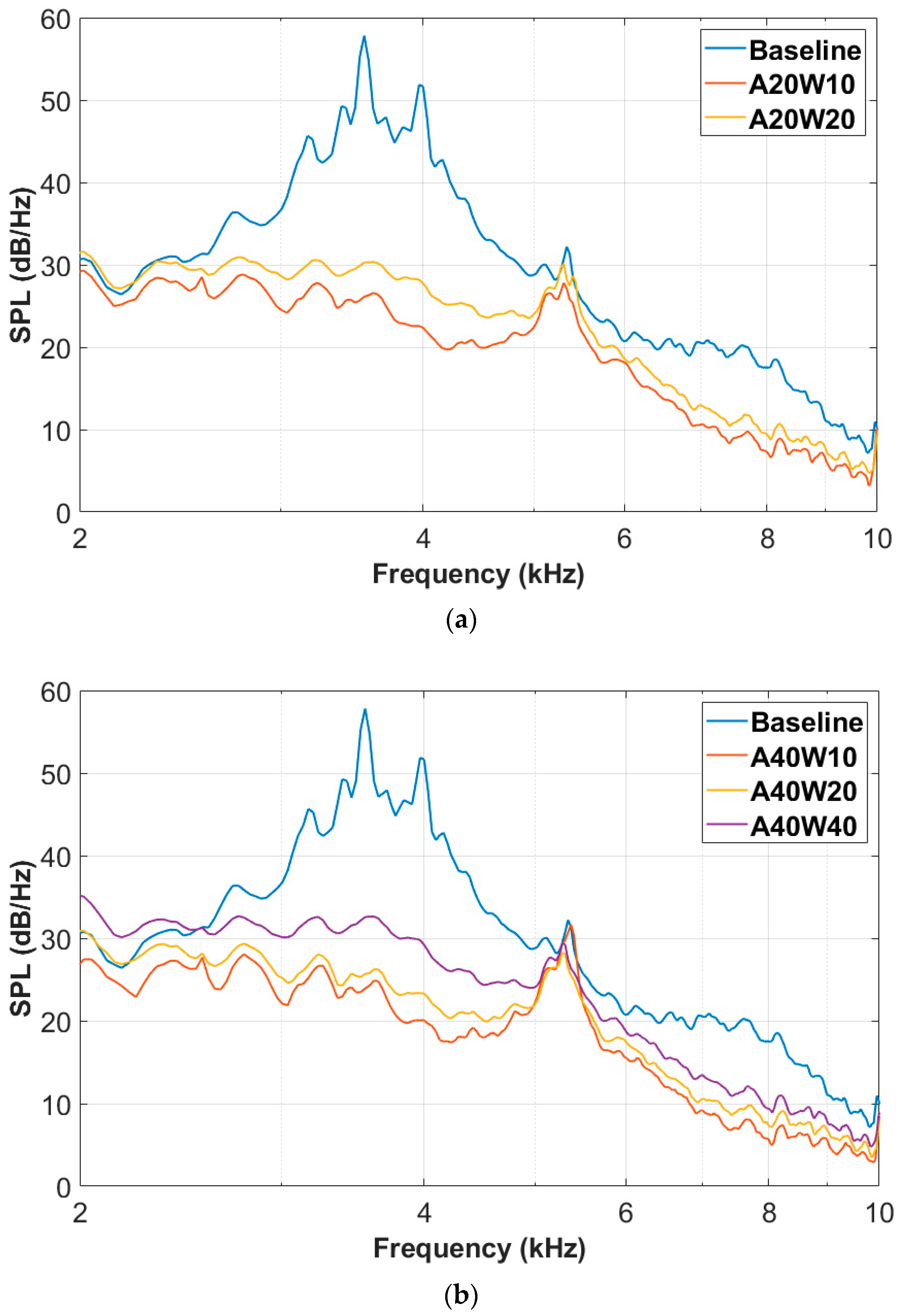
3.2. Noise Reduction Effect of the Wavy Airfoil

Figure 9 shows the sound source identification results of the baseline airfoil, A10W20 airfoil and A40W20 airfoil when the incoming flow velocity is 50 m/s and the attack angle is 10°. The display range of the contour of the sound pressure level at the same frequency is the same. It can be observed that for all airfoils, noise is concentrated in the middle of the airfoil trailing edge. The wavy leading edges can effectively control the airfoil trailing edge noise, and the A40W20 airfoil with a larger amplitude has a much better noise reduction effect on the airfoil trailing edge noise than the A10W20 airfoil.
The influence of the amplitude of the wavy leading edges on the trailing edge noise sound pressure level spectrum is shown in Figure 10. The incoming flow velocity is 50 m/s, and the geometric angle of attack is 10°, the same below. It can be concluded that when the wavelength of the wavy leading edges remains consistent, the larger the amplitude, the better the noise reduction effect. Figure 10a,b have the same noise reduction law for different wavelengths. We can also see that when the amplitude-to-wavelength ratio (A/W) of the wavy leading edges is the same, such as A5W10 and A10W20 or A20W10 and A40W20, the noise spectrum of the wavy airfoils is similar, and the level of noise reduction is comparable. However, in Figure 10a, when the ratio A/W of the wavy leading edge increases to 4, the noise reduction benefits of the A40W10 wavy airfoil are relatively small compared to the A20W10 wavy airfoil.
The influence of the wavelength of the wavy leading edges on the trailing edge noise radiation is shown in Figure 11. It can be observed from Figure 11a that when the amplitude is 0.2 c, the A20W10 airfoil has a better noise reduction effect compared to the A20W20 airfoil. Similarly, in Figure 11b, when the amplitude remains at 0.4 c, the noise reduction effect worsens with an increase in wavelength. Moreover, the A40W40 airfoil leads to an increase in the sound pressure level between 2000 and 2500 Hz.
According to our research, it can be concluded that all the wavy leading edges studied in this paper have the effect of reducing airfoil trailing edge noise, including hump noise and broadband noise. Moreover, the wavy leading edge with a larger amplitude and smaller wavelength can control the trailing edge noise better. Especially, the A40W10 airfoil is found to have the most effective noise reduction capabilities. It has been obtained that the trailing edge hump noise due to the increased angle of attack ranging from 2500 to 5000 Hz is completely suppressed by the A40W10 airfoil, with a maximum noise reduction level of 33.9 dB at 3552 Hz. Additionally, the broadband noise between 5600 and 10,000 Hz has also been effectively reduced, with a maximum noise reduction level of 12.7 dB at around 7500 Hz. Secondly, the wavy airfoils A40W20 and A20W10 are also effective for noise reduction, achieving a maximum sound pressure level reduction of 32.1 dB and 31.7 dB at 3552 Hz, respectively.
There are some limitations to this study: (1) The research object used in this study is a two-dimensional symmetric airfoil, which simplifies the actual blade without considering its three-dimensional characteristics. However, the blade shape and twist angle of the actual wind turbine at different radius positions are different. (2) This study simulates the actual situation at different radii of the blade by changing the angle of attack and inflow velocity. However, the range of angle of attack and velocity in this study is limited, and only the velocity range of 20–70 m/s is studied under small angles of attack. In fact, the wavy leading edge also has a certain control effect on flow separation at high angles of attack, which can effectively reduce the separation noise of airfoil. (3) This study was conducted in a semi-anechoic chamber, so the impact of background noise is relatively significant. The low-frequency noise below 2000 Hz and the hump noise near 5200 Hz are dominated by background noise, which may mask the airfoil noise under some incoming flow conditions.

4. Conclusions

This paper experimentally investigates the noise radiation characteristics of the baseline NACA 0012 airfoil and seven wavy leading edge airfoils with different amplitudes and wavelengths at seven speeds ranging from 20 to 70 m/s and four angles of attack from 0° to 15°. The influence of the amplitude and wavelength of the wavy leading edges on the noise reduction effect was analyzed. And through beamforming sound source recognition technology, the distribution of sound sources and the noise reduction effect of wavy leading edge configurations were intuitively presented. Based on the experimental results, the following conclusions are drawn.
The broadband noise radiated by the baseline airfoil generally increases with the increase in the incoming flow velocity. At the same time, due to the existence of the angle of attack, hump noise will be generated, and broadband noise will be increased. Moreover, the frequency of the noise hump will gradually increase with the increase in the incoming flow velocity, while the noise peak will first increase and then decrease with the increase in the velocity. In the range of small angles of attack, the sound pressure level of the baseline airfoil increases with the increase in angle of attack, and the main noise source is located at the trailing edge of the airfoil. At 10° angle of attack and 50 m/s, the maximum sound pressure level can reach up to 76 dB at 3552 Hz, with an increase of 23 dB compared to the 53 dB at 0° angle of attack.
The wavy leading edges can effectively control the airfoil trailing edge noise, and the wavy leading edge with a larger amplitude and smaller wavelength can achieve a better noise reduction effect. For example, when the incoming flow speed is 50 m/s, the wavy leading edges effectively suppress the hump noise in the range of 2500–5000 Hz, while also effectively reducing the broadband noise above 5600 Hz. Among the airfoils studied, the A40W10 airfoil demonstrated the most effective noise reduction, achieving a maximum reduction of up to 33.9 dB in airfoil trailing edge noise, from 57.8 dB for the baseline airfoil to 23.9 dB for the A40W10 airfoil.

Author Contributions

Conceptualization, W.C.; methodology, W.C. and Y.X.; software, Y.X.; validation, W.C., W.Q. and F.T.; formal analysis, Y.X. and W.C.; investigation, Y.X. and X.W.; resources, W.Q.; data curation, X.W.; writing—original draft preparation, Y.X., X.W., W.C., W.Q. and F.T.; writing—review and editing, Y.X. and W.C.; visualization, Y.X.; supervision, F.T.; project administration, Y.X. and X.W.; funding acquisition, W.Q. and F.T. All authors have read and agreed to the published version of the manuscript.

Funding

This research was funded by the National Natural Science Foundation of China (No. 52106056), the Science Center for Gas Turbine Project (No. P2022-A-II-003-001, P2022-B-II-011-001), the National Science and Technology Major Project of China (No. 2017-II-0008-0022, J2019-II-0013-0034), the Fundamental Research Funds for the Central Universities, the National Key Laboratory of Science and Technology on Aerodynamic Design and Research (No. 614220121050103), and the Key Laboratory of Aerodynamic Noise Control (No. ANCL20210104, ANCL20220101).

Data Availability Statement

The data are available from the corresponding author upon reasonable request.

Conflicts of Interest

The authors declare no conflict of interest.

References

  1. Lund, H. Renewable energy strategies for sustainable development. Energy 2007, 32, 912–919. [Google Scholar] [CrossRef] [Green Version]
  2. Global Wind Energy Council. Global Wind Report 2023. Available online: https://gwec.net/globalwindreport2023/ (accessed on 2 May 2023).
  3. Saidur, R.; Rahim, N.A.; Islam, M.R.; Solangi, K.H. Environmental impact of wind energy. Renew. Sustain. Energy Rev. 2011, 15, 2423–2430. [Google Scholar] [CrossRef]
  4. Baudin, C.; Lefèvre, M.; Champelovier, P.; Lambert, J.; Laumon, B.; Evrard, A.-S. Aircraft Noise and Psychological Ill-Health: The Results of a Cross-Sectional Study in France. Int. J. Environ. Res. Public Health 2018, 15, 1642. [Google Scholar] [CrossRef] [Green Version]
  5. Ageborg, M.J.; Smith, M.G.; Ogren, M.; Thorsson, P.; Pedersen, E.; Forssen, J.; Persson, W.K. Wind turbine noise and sleep: Pilot studies on the influence of noise characteristics. Int. J. Environ. Res. Public Health 2018, 15, 2573. [Google Scholar] [CrossRef] [PubMed] [Green Version]
  6. Gaßner, L.; Blumendeller, E.; Müller, F.J.; Wigger, M.; Rettenmeier, A.; Cheng, P.W.; Hübner, G.; Ritter, J.; Pohl, J. Joint analysis of resident complaints, meteorological, acoustic, and ground motion data to establish a robust annoyance evaluation of wind turbine emissions. Renew. Energy 2022, 188, 1072–1093. [Google Scholar] [CrossRef]
  7. Whalen, C.E.; Bomberger Brown, M.; McGee, J.; Powell, L.A.; Walsh, E.J. Effects of wind turbine noise on the surrounding soundscape in the context of greater-prairie chicken courtship vocalizations. Appl. Acoust. 2019, 153, 132–139. [Google Scholar] [CrossRef]
  8. Hansen, C.; Hansen, K. Recent Advances in Wind Turbine Noise Research. Acoustics 2020, 2, 171–206. [Google Scholar] [CrossRef] [Green Version]
  9. Hornung, C.; Lutz, T.; Krämer, E. Development of design guidelines for low noise but high yield wind turbines. In Proceedings of the 8th International Conference on Wind Turbine Noise, Lisbon, Portugal, 12–14 June 2019. [Google Scholar]
  10. Oerlemans, S.; Sijtsma, P.; López, B.M. Location and quantification of noise sources on a wind turbine. J. Sound Vib. 2007, 299, 869–883. [Google Scholar] [CrossRef]
  11. Brooks, T.F.; Pope, D.S.; Marcolini, M.A. Airfoil Self-Noise and Prediction (NASA Reference Publication); Technical Report 1218; National Aeronautics and Space Administration: Washington, DC, USA, 1989.
  12. Lutz, T.; Herrig, A.; Würz, W.; Kamruzzaman, M.; Krämer, E. Design and wind-tunnel verification of low-noise airfoils for wind turbines. AIAA J. 2007, 45, 779–785. [Google Scholar] [CrossRef]
  13. Sanghyeon, K.; Cheolung, C. Development of low-noise drag-type vertical wind turbines. Renew. Energy 2015, 79, 199–208. [Google Scholar]
  14. Avallone, F.; Van Der Velden, W.C.P.; Ragni, D.; Casalino, D. Noise reduction mechanisms of sawtooth and combed-sawtooth trailing-edge serrations. J. Fluid Mech. 2018, 848, 560–591. [Google Scholar] [CrossRef] [Green Version]
  15. Zhao, M.; Cao, H.; Zhang, M.; Liao, C.; Zhou, T. Optimal design of aeroacoustic airfoils with owl-inspired trailing-edge serrations. Bioinspir. Biomim. 2021, 16, 056004. [Google Scholar] [CrossRef] [PubMed]
  16. Showkat, A.S.A.; Azarpeyvand, M.; Ilário, D.S.C.R. Trailing-edge flow and noise control using porous treatments. J. Fluid Mech. 2018, 850, 83–119. [Google Scholar] [CrossRef] [Green Version]
  17. Fish, F.E.; Battle, J.M. Hydrodynamic design of the Humpback Whale Flipper. J. Morphol. 1995, 225, 51–60. [Google Scholar] [CrossRef] [PubMed]
  18. Hansen, K.L.; Kelso, R.M.; Doolan, C.J. Reduction of flow induced tonal noise through leading edge tubercle modifications. In Proceedings of the 16th AIAA/CEAS Aeroacoustics Conference, Stockholm, Sweeden, 7–9 June 2010; p. 3700. [Google Scholar]
  19. Gruber, M.; Joseph, P.F.; Polacsek, C.; Chong, T.P. Noise reduction using combined trailing edge and leading edge serrations in a tandem airfoil experiment. In Proceedings of the 18th AIAA/CEAS Aeroacoustics Conference (33rd AIAA Aeroacoustics Conference), Colorado Springs, CO, USA, 4–6 June 2012; p. 2134. [Google Scholar]
  20. Feinerman, J.A.; Koushik, S.; Schmitz, F.H. Effect of leading-edge serrations on helicopter blade-vortex interaction noise. J. Am. Helicopter Soc. 2017, 62, 1–11. [Google Scholar] [CrossRef]
  21. Chen, W.J.; Qiao, W.Y.; Tong, F. Experimental investigation of wavy leading edges on rod-aerofoil interaction noise. J. Sound Vib. 2018, 422, 409–431. [Google Scholar] [CrossRef]
  22. Stahl, K.; Manegar, F.; Carouls, T.; Binois, R. Experimental investigation of self-aligning trailing edge serrations for airfoil noise reduction. In Proceedings of the 8th International Conference on Wind Turbine Noise, Lisbon, Portugal, 12–14 June 2019. [Google Scholar]
  23. Chaitanya, P.; Joseph, P.; Narayanan, S. Performance and mechanism of sinusoidal leading edge serrations for the reduction of turbulenc-aerofoil interaction noise. J. Fluid Mech. 2017, 818, 435–464. [Google Scholar] [CrossRef] [Green Version]
  24. Aguilera, F.G.; Gill, J.; Angland, D. Wavy leading edge airfoils interacting with anisotropic turbulence. In Proceedings of the 23rd AIAA/CEAS Aeroacoustics Conference, Denver, CO, USA, 5–9 June 2017; p. 3370. [Google Scholar]
  25. Chen, W.J.; Qiao, W.Y.; Tong, F.; Wang, L.F.; Wang, X.N. Numerical investigation of wavy leading edges on rod-airfoil interaction noise. AIAA J. 2018, 56, 2553–2567. [Google Scholar] [CrossRef]
  26. Chen, W.; Qiao, W.; Duan, W.; Wei, Z. Experimental study of airfoil instability noise with wavy leading edges. Appl. Acoust. 2021, 172, 107671. [Google Scholar] [CrossRef]
  27. Lacagnina, G.; Chaitanya, P.; Kim, J.H.; Berk, T.; Joseph, P.; Choi, K.S.; Ganapathisubramani, B.; Hasheminejad, S.M.; Chong, T.P.; Stalnov, O.; et al. Leading edge serrations for the reduction of aerofoil self-noise at low angle of attack, pre-stall and post-stall conditions. Int. J. Aeroacoust. 2021, 20, 130–156. [Google Scholar] [CrossRef]
  28. Kim, J.H.; Choi, K.S.; Lacagnina, G.; Chaitanya, P.; Joseph, P.; Hasheminejad, S.M.; Pei Chong, T.; Shahab, M.F.; Omidyeganeh, M.; Pinelli, A. Aerodynamic and aeroacoustic optimization of leading-edge undulation of a naca 65 (12)-10 airfoil. AIAA J. 2022, 60, 2342–2353. [Google Scholar] [CrossRef]
  29. Brooks, T.F.; Marcolini, M.A.; Pope, D.S. Airfoil Trailing-Edge Flow Measurements. AIAA J. 1986, 24, 1245–1251. [Google Scholar] [CrossRef]
  30. Sijtsma, P. CLEAN based on spatial source coherence. Int. J. Aeroacoust. 2007, 6, 357–374. [Google Scholar] [CrossRef]
  31. Biedermann, T.M.; Czeckay, P.; Geyer, T.F.; Kameier, F.; Paschereit, C.O. Effect of inflow conditions on the noise reduction through leading edge serrations. AIAA J. 2019, 57, 4104–4109. [Google Scholar] [CrossRef]
  32. Welch, P.D. The use of fast Fourier transform for the estimation of power spectra: A method based on time averaging over short, modified periodograms. Audio Electroacoust. 1967, 15, 70–73. [Google Scholar] [CrossRef] [Green Version]
Figure 1. Design of wavy leading edge airfoil: (a) design parameters; (b) spanwise section generation.
Energies 16 05865 g001
Figure 2. Practical photograph of the wavy leading edge airfoils.
Energies 16 05865 g002
Figure 3. Schematic diagram of anechoic chamber and wind tunnel.
Energies 16 05865 g003
Figure 4. Photograph of the experiment environment.
Energies 16 05865 g004
Figure 5. Microphone array panel: (a) geometric model; (b) practical photograph.
Energies 16 05865 g005
Figure 6. Comparison of noise radiation of the baseline airfoil at different speeds and angles of attack: (a) AOA = 0° (with background noise); (b) AOA = 10°.
Energies 16 05865 g006
Figure 7. Comparison of noise radiation of the baseline airfoil at different angles of attack: (a) 40 m/s; (b) 50 m/s; (c) 60 m/s.
Energies 16 05865 g007aEnergies 16 05865 g007b
Figure 8. Distribution of sound sources at different angles of attack of the baseline airfoil: (a) AOA = 0°, f = 4000 Hz; (b) AOA = 10°, f = 4000 Hz; (c) AOA = 0°, f = 8000 Hz; (d) AOA = 10°, f = 8000 Hz.
Energies 16 05865 g008aEnergies 16 05865 g008b
Figure 9. Distribution of sound sources for different airfoils: (a) Baseline at f = 4000 Hz; (b) A10W20 at f = 4000 Hz; (c) A40W20 at f = 4000 Hz; (d) Baseline at f = 8000 Hz; (e) A10W20 at f = 8000 Hz; (f) A40W20 at f = 8000 Hz.
Energies 16 05865 g009
Figure 10. The effect of the wavy amplitude on noise reduction: (a) W = 0.1 c; (b) W = 0.2 c.
Energies 16 05865 g010
Figure 11. The effect of the wavy wavelength on noise reduction: (a) A = 0.2 c; (b) A = 0.4 c.
Energies 16 05865 g011
Table 1. Design parameters for test airfoils.
NameA (mm)W (mm)A/c (%)W/c (%)A/WWave Number
Baseline------------
A5W105105100.520
A20W1020102010220
A40W1040104010420
A10W20102010200.510
A20W2020202020110
A40W2040204020210
A40W404040404015
Disclaimer/Publisher’s Note: The statements, opinions and data contained in all publications are solely those of the individual author(s) and contributor(s) and not of MDPI and/or the editor(s). MDPI and/or the editor(s) disclaim responsibility for any injury to people or property resulting from any ideas, methods, instructions or products referred to in the content.

