Abstract
There is a growing demand from the industrial sector and the population to cover the need for water temperature increases that can be covered with systems such as heat pumps. The present research aims to increase the heat transfer to the working fluid in a collector/evaporator, part of a solar-assisted direct expansion heat pump. This research was developed using a numerical analysis and by applying computational fluid dynamics; different simulations were performed to compare the performances of collector/evaporators with models exhibiting variations in the cross-section profile under similar conditions. An average incident solar radiation of 464.1 W·m−2 was considered during the analysis. For the comparison, profiles with hexagon-, four-leaf clover-, and circular-shaped sections with floral shapes, among others, were analysed, resulting in a temperature increase at the outlet of the working fluid of 1.3 °C. In comparison, the collector/evaporator surface temperature varied between 4 and 13.8 °C, while the internal temperature of the fluid reached 11.21 °C. Finally, it is indicated that the best results were presented by analysing the profile corresponding to the circular section with the flower shape.
1. Introduction
These days, the environmental consequences related to the consumption of energy generated by fossil sources are a wake-up call to the scientific community to improve the performance of systems that work with renewable energy, like solar energy [1,2]. Solar power is significant among global renewable energy sources due to its abundant energy potential [3]. The use of solar energy for several processes is advantageous for reducing the energy consumption of conventional systems and protecting the environment [4]. The direct-expansion solar-assisted heat pump system is employed for heating different fluids using refrigerants as working fluids since they have a series of environmentally acceptable thermodynamic (evaporating pressure, boiling, critical, and freezing temperature) and physicochemical (low flammability and toxicity) properties [5].
Direct-expansion solar-assisted heat pumps (DX-SAHP) can be used in different fields with significant energy savings, as stated by Ji et al. [6], considering the different design and operating factors such as relative humidity, which produces an increase of 16.3% in the coefficient of performance (COP) of the flat plate device without cover when it is raised from 70% to 90%. In recent investigations like the studies by Neelamegam and Amirtham [7] and Jamali [8], and in the search for better performances in devices that contribute to solar energy, global solar radiation is an essential parameter for designing solar energy systems. In addition, flat plate solar collectors have led to the integration of new materials after an experimental and numerical validation with CFD simulation software Ansys Fluent (https://simutechgroup.com/ansys-software/fluids/fluent/, accessed on 1 July 2023), where the data obtained with the simulation with actual data, as proposed by Zhou et al. [9], achieved an increase of 11.3% in the efficiency of a solar collector; furthermore, Nandanwara [10] improved the COP of a refrigeration system around 7%.
It is possible to determine different parameters that influence solar-assisted heat pump performance with the aid of numerical models which take into account continuity, momentum, and energy conservation equations to varying values of temperature, pressure, enthalpy, mass flow, and density, among others; despite the presence of some errors smaller than 6%, they show their validity when contrasted with experimental results, achieving a 60.2% reduction in electricity consumption when the temperature of 2.5 L·min−1 of water is increased from 25 to 32 °C, compared to the same process using electrical resistances [11].
In addition, to improve the efficiency of flat plate collector/evaporators, as has been done in simulation works such as Sun et al. [12], different pipe patterns are simulated to find a new configuration that improves the global COP of a DX-SAHP heating system. The lack of research about geometric changes in a collector/evaporator has been evidenced in several peer-reviewed works where new information is required to benefit the thermodynamic field. Therefore, in the study by Andrade et al. [13] about the efficiency of a flat-plate solar collector when the cross sections are varied, it is indicated that, with a hydraulic diameter of 10 mm, temperatures up to 330 K are reached at the outlet of the device with an efficiency of 68%, a circular section, and a pressure of 108.3 Pa; these results were obtained through a CFD analysis using water as a working fluid. In addition, to evaluate the COP of a DX-SAHP system, a comprehensive thermodynamic evaluation can be performed considering a cascade refrigeration system using hydrocarbon refrigerants [14,15].
The research carried out in this study is focused on increasing or improving solar energy usage. It involves managing the heat flow, where CFD software is used to validate the temperatures achieved. As explained by Panchal and Patel [16], the geometry and mesh of the construction model are realised using software for different applications (solar collectors and drying chambers, among others). The CFD validation exhibits acceptable results in the design and improvement of compact heat exchangers, as can be appreciated in the study by Abeykoon [17], who demonstrate that this type of validation may be utilised for different design options without requiring the manufacturing of prototypes that employ working fluids with different thermodynamic properties. Considering research works like those by Abeykoon [17], it is essential to emphasise the improvement of the DX-SAHP system’s performance, which is directly related to the efficiency of its components, such as the collector/evaporator, which has been studied by authors like Combariza et al. [11] and Sun et al. [12]. Nevertheless, these works did not investigate the influence of geometric variation in the cross-section of the heat flux in order to improve the efficiency of this device. This research aims to conduct CFD simulations and numerical analysis of various geometric profiles that are different from the traditional circular pipe to obtain results through a comparative figure to show improvement through a more significant outlet temperature than the original model.
2. Materials and Methods
In the current research work, a comparative study about the increase of the heat transfer in a collector/evaporator, which can be appreciated in Figure 1, is carried out using R600a refrigerant as a working fluid. This study references the experimental results of a base model of the heat exchanger presented by Quitiaquez et al. [18] to perform a numerical and a CFD analysis in models considering different cross sections with the same area of the base case.
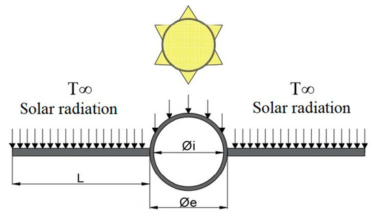
Figure 1.
Heat transfer in a solar collector [19].
The study included an experimental case presented by Quitiaquez et al. [18] where the original geometry of the channel in the collector/evaporator is circular with a cross-sectional area of 1.1341 × 10⁻⁵ m2; for comparison purposes, the area is preserved and different new configurations are implemented. In this way, we adopt a criterion for selecting new geometric profiles according to the Nusselt number (Nu) that such profiles may offer, with Nu being equal to 4.36 for the case of laminar flow for a circular profile, which is more significant compared to 4.002 for a regular polygon (hexagonal) profile. Values found by Kreith et al. [20] show a trend at first sight that, for regular polygons with straight sides, there is a more extensive loss of heat transfer compared to curvilinear profiles. Therefore, to verify the abovementioned information, profiles with a “hexagonal” shape were chosen to visualise a behaviour pattern as a function of the curves that a profile may show, obtaining as a result, as the profile has more curves, that it has a larger heat transfer. Considering the previous argument, the pair of profiles subsequently chosen were “three-leaf clover” (3L Clover) and “four-leaf clover” (4L Clover), as the tube’s external wings help to disperse the heat to the environment, and an inverse one may improve the heat transfer; therefore, the last pair of profiles chosen were “flower” and “internal circular section with flower in the external profile” (flower in the external profile).
2.1. Experimental Parameters
To analyse the proposed models and obtain their results from the initial case, it is necessary to consider the conditions under which the base model was developed, as shown in Table 1, to use them as parameters in the proposed CFD analyses and realise a validation. In the research carried out by Quitiaquez et al. [19], the total set of specifications of the base model for the simulation was detailed; additionally, a network diagram of thermal resistances was made in which the influence of the heat transfer mechanisms present in the analysis of the collector/evaporator are explained.

Table 1.
Inlet conditions for the flat-plate solar collector without cover.
On the other hand, Table 2 shows the thermophysical properties of refrigerant R600a at saturation temperature and boundary conditions.

Table 2.
Thermophysical properties of refrigerant R600a.
2.2. Governing Equations in the Numerical Analysis
To obtain the numerical analysis results for the proposed models, it is necessary to consider the parameters in Table 1 in the equations that govern the behaviour of the fluids in the heat exchange devices to determine the specific properties that influence the analysis results. The hydraulic diameter (Dh) changes due to the chosen configurations; according to Equation (1), this is a function of the cross-sectional area, which is constant in all profiles, while the perimeter varies depending on the geometric shape [19].
The Reynolds number (Re), Equation (2), relates the physical properties of the fluid, its velocity, and the geometry of the pipeline through which it flows (enabling us to determine the laminar or turbulent flow) to the fluid velocity (V), the hydraulic diameter of the pipeline (Dh), and kinematic viscosity (v) [21].
when Re is in the interval between 2300 and 10,000, it is known that the flow is in a state of transition from laminar to turbulent flow. At the same time, the Nusselt number (Nu) becomes essential for the heat flow amount that the fluid transports. It is evaluated as a transition regime, a ratio between laminar and turbulent flow. Considering this regime, the Nusselt number is calculated using Equation (3).
therefore, Equation (4) considers the boundary condition for laminar flow at a constant temperature [22].
Correlations for turbulent regimes are detailed in Equations (5) and (6) [23].
similarly, the correction of Equation (7) determines the temperature for any length of the pipeline, considering that the value of the surface area is a function of the length and that this equation shows an error smaller than 1%. At this point, it is highlighted that the value of the number of transfer units (NTU) is smaller than 5, and the temperature at the outlet is not close to the surface temperature (Ts).
2.3. CFD Analysis
When performing the computational fluid dynamics analysis, the finite volume method is considered to solve equations that relate to the conservation of mass, momentum, and energy [24]. For the present case study, ANSYS 2021 software with the (Fluent) module was used to consider specific parameters in the development of the fluid passing through the collector/evaporator with the Eulerian model, determining results such as temperature along the heat exchanger, pressure variation, and heat flow, among others.
2.3.1. Mesh
Due to the variety of models proposed, it was required to perform an independent mesh in each case to validate the modelling. However, since the heat flows in the solid–fluid interface were calculated by integration, all proposed models required a refined mesh in this area [25]. As can be observed in Figure 2, a non-structured mesh was used in the CFD analysis, preserving a mesh quality smaller than 0.25 in skewness and generating an independent distribution of elements to improve the mesh according to the geometry with the mesh tool of the simulation software [26]. In addition, the mesh used was of adequate quality. After performing a test with refinement in the boundary layer, there was no significant change in the overall results or in that area, despite a considerable increase in the mesh elements. Specific coefficients considered in the turbulence model are set by default in the simulator, and their applicability in the simulation was checked in the validation process.
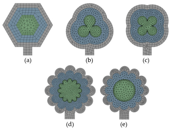
Figure 2.
Mesh in the models. (a) Hexagonal; (b) 3L Clover (c) 4L Clover; (d) Flower; (e) Internal circular section with a flower shape in the external profile.
In meshing the proposed model and all those presented in this research, a remarkable refinement was made in the section changes that were present. In this way, the details were incorporated, and a correct CFD analysis of the heat transfer at the solid–fluid interface was generated, and, consequently, adequate temperature changes were achieved. In the validation process of the models used, where experimental parameters were used for a collector/evaporator, which is part of a DX-SAHP system, there was a percentage error margin of less than 15% between the experimental output temperature and the one obtained by CFD analysis. In order to evaluate whether the mesh used presented the appropriate characteristics for CFD analysis, the average values of the mesh metrics were considered, as presented in Table 3, meshing with a minimum orthogonal quality >0.1 [27]. Moreover, for solar collectors, the convergence of the meshing to the outlet temperature can be achieved considering a Skewness quality lower than 0.25 [19]; for this reason, the criterion was considered for meshing the models.

Table 3.
Mesh metrics.
2.3.2. Governing Equations
The CFD analysis to determine the behaviour of the fluids uses a series of Navier–Stokes equations, which are simultaneously solved to satisfy the conservation of mass (continuity), momentum, and energy in case there is heat transfer, as shown in Equations (8), (9), and (10), respectively [9].
Another essential factor in the CFD analysis is the flow regime of the refrigerant, and this is the reason why, in this investigation, the k-Ɛ RNG turbulence model was used, governed by Equations (11) and (12), which shows results with great precision, outstanding reliability, and possibly a more negligible computational cost [28].
For the case of models that require a phase change in a fluid, the program solves a group of equations to achieve convergence in the simulation result with the Eulerian Model, among which there are: the continuity, energy, and momentum equations, corresponding to Equations (13), (14), and (15), respectively [29].
Additionally, as part of the numerical consideration for the analysis, the pressure–velocity coupling scheme and the discretization for pressure, momentum, and energy, among others, are highlighted (Table 4).

Table 4.
Analysis consideration.
3. Results and Discussion
The results obtained in this investigation considered experimental parameters like ambient temperature, incident solar radiation, and mass flow, among others, to generate a comparative analysis between the influence of different cross sections and how they can improve the heat flux in the collector evaporator.
3.1. Validation
Duarte et al. [30], in their study, presented errors below 6% between their experimental results and numerical analysis. The base case outlet temperature of 9.5 °C obtained in an experimental investigation was used to validate the numerical analysis with the mathematical algorithm generated, as well as CFD models in a transient state with time steps of 0.01 s, presenting errors of 0.105 and 1.12%, respectively, for which the values are presented in Table 5. In addition, as in the investigation of Li and Vasquez [31], in a multiphase CFD analysis realised in a steady and unsteady state, results near experimental values can be obtained.

Table 5.
Outlet temperature.
The base case outlet temperature obtained in the CFD analysis considers the value in the centre zone of the circular pipe, as can be appreciated from Figure 3, with the maximum values in the zone near the wall being 9.5 °C.
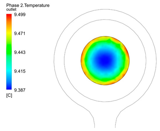
Figure 3.
Outlet temperature of the CFD analysis.
3.2. Cross Section Profiles Results
Through a comparative analysis, it was determined that an increase in the heat transfer to the working fluid can be noticed in the outlet temperature in the models of profiles with shapes of hexagon, 3L Clover, 4L Clover, flower, and flower in the external profile, in the cross section. with The results are presented in Figure 4a–e.
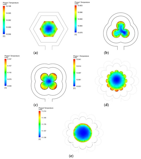
Figure 4.
Temperature at the outlet of the collector/evaporator in cases (a–e).
In Figure 4a, an outlet temperature of the working fluid varying between 10.05 and 10.10 °C has been generated. The highest temperatures are at the geometry’s vertices, while the lowest values are in the centre of the working fluid. In the superficial part, a maximum temperature of 13.00 °C is displayed, which shows that the collector/evaporator continues to gain heat by convection and radiation. The maximum temperature obtained in the central part in configuration 4b (three-leaf clover) is 10.90 °C, while the minimum is 10.87 °C. This shows that the working fluid is leaving the collector/evaporator as superheated steam and thus does not generate any damage to the compressor. The surface temperature in this geometry is, on average, 11.20 ° C.
The third configuration under study, presented in Figure 4c, is a four-leaf clover, where the maximum surface temperature is 12.76 °C, while the average temperature of the refrigerant is 9.12 °C. Figure 4d displays the fourth configuration to be analysed, the 11-petal flower. For this shape, the working fluid temperature ranges between 10.83 and 10.94 °C, while the surface temperature reaches a maximum of 13.51 °C. This temperature is 3.92% and 5.89% higher than the surface temperatures reached with the hexagon and four-leaf clover configurations, respectively. This analysis considers that the configurations that present curves in the geometry improve the heat transfer to R600a.
Finally, the configuration called the 11-petal flower with a circular profile, presented in Figure 4e, is presented. It represents a geometry that demands a complex meshing in the curved surfaces, and this configuration presents the best heat transfer when compared to the cases presented above. It has a maximum temperature in the working fluid of 11.21 °C, higher by approximately 2.5% than the 11-petal flower model. This last configuration, compared with the base case, which presented a temperature at the coolant outlet of 9.5 °C, is higher by 18%. The surface temperature of this case reaches minimum and maximum temperatures of 9.43 and 13.84 °C, respectively; the ambient temperature is 17.6 °C. This evidences the improvement of the collector/evaporator in terms of convection and radiation, allowing this device to operate at any time of the day and making it different from the rest of the collectors.
Figure 5 shows the kinetic energy turbulence at the outlet for each model presented, highlighting a more comprehensive range for the 3L Clover model, which has a maximum value of 1.597 m2s·−2 and a minimum value of 0.085 m2·s−2. Likewise, the Turbulence Eddy Dissipation is considered in the output of the models. In that case, it can be seen that the maximum value (15,378.532 m2·s−3) is presented in the 3L Clover model. In contrast, the final model, with the internal circular section with a flower shape in the external profile, presents the minimum value (78.962 m2·s−3), as shown in Figure 6.
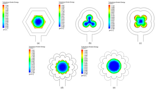
Figure 5.
Turbulence Kinetic Energy in cases (a−e).
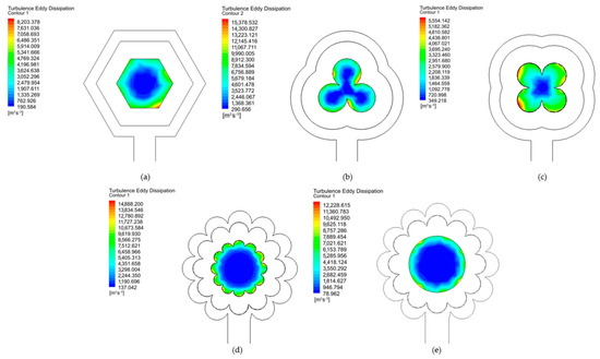
Figure 6.
Turbulence Eddy Dissipation in cases (a−e).
Results Comparison
The configurations proposed in the present research are the most relevant; previously, some additional simulations were carried out that served as a guide for obtaining new geometries that increase the heat transfer; proof of this is the research carried out by Andrade et al. [13]. The temperature distribution over the entire surface section of the collector/evaporator in all of the simulated cases resembles that obtained by Gunjo et al. [32]. The authors performed a computational simulation, considering the solar radiation as proposed in the present investigation. Figure 7 is shown below, in which a comparison between the maximum fluid temperatures obtained in each case analysed (A—Hexagon, B—3L Clover, C—4L Clover, D—Flower and E—Flower in the external profile/Flower 2) in this section of the paper is developed. From this information, it can be determined that case e (11-petal flower with circular profile) is the geometry that presents the best heat transfer to the working fluid.
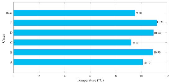
Figure 7.
Outlet temperature comparison for the all cases analysed, A: Hexagonal; B: 3L Clover; C: 4L Clover; D: Flower; E: Internal circular section with a flower shape in the external profile.
The results obtained in the simulations were analyzed and compared with the experimental results that were initially achieved. To contrast the results, specific regions of the collector/evaporator, such as a region 0.1 mm inside the conduct from the fluid, may be considered to find the case with the more significant temperature along the heat transfer device and verify the heat flow increase, as can be seen in Figure 8.
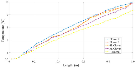
Figure 8.
Grouped values of the outlet temperatures.
Table 6 shows the results obtained by comparing the numerical modelling with the CFD simulation, obtaining outlet temperature variations of one centesimal degree, which validates the criteria, equations, and the reasoning employed in the execution of the simulations, as well as showing that, indeed, there exist geometric configurations aside from the tubular shape traditionally employed that help to improve the heat transfer. To improve the visualisation of the results concerning the outlet temperature of the working fluid, a comparative plot is shown (Figure 9) that indicates an increase in the value of the outlet temperature for the configurations corresponding to the 3L Clover, 4L, flower, and flower in the external profile, with the base case experimental result (original).

Table 6.
Geometric properties of the different models.
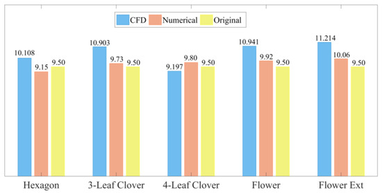
Figure 9.
Comparison between the results obtained with the CFD simulation and the numerical analysis with changes in the geometric profile of the refrigerant pipeline, including the outlet temperature’s original value.
4. Discussion
An increase associated with a more extensive surface section in the duct coating is observed when considering the outlet temperature of the analysed models. This, in each case, is verified due to the cross-sectional shape of each geometrical shape and the increase in area associated with the curvatures that were implemented. A cross-section analysis to measure snow depth, density, and snow water equivalent was applied by Kaasik et al. [33]; the cross-section area varied from 11 to 100 cm2, and the length of the pipe from 30 to 100 cm. As in the present research, the thinner samplers underestimate the snow water equivalent. When considering this research, better results are obtained when usingdifferent equipment with a variation in the cross section. On the other hand, in the research of Andrade et al. [13], the efficiency of the flat-plate solar collector is evaluated, as well as the behaviour of the fluid inside the pipe; three different cross sections were considered with hydraulic diameters of 10, 5.12, and 6.16 mm, using ANSYS Fluent. The circular geometry presented a better performance and improved the heat transfer from the environment to the fluid. This research was considered to be a basis for further study of cross-sectional area change. Likewise, Rukruang et al. [34] analyzed the thermal performance of tubes with alternating cross sections, indicating that tubes with alternating cross sections have improved vorticity, improving the tube’s thermal performance. In addition, Mimi-Elsaid et al. [35] indicate that using a circular cross section of a helical tube has a higher heat transfer-per-unit pumping power that is higher than that of the elliptical cross section of a helical tube and the square cross section of a helical tube by approximately 23.08% and 84.61%, respectively. These parameters are also evidenced in the present research.
5. Conclusions
- The application of the ecological refrigerant R600a has impacts of great importance, both in industry and ecologically, because it has an ODP of 0 and a GWP of 3 compared to the family of HFCs and HCFCs that have ODPs of 0 and 0.05, and GWPs of 1300 and 1700, respectively. In the industry, as they have significantly better thermal characteristics, they are used to carry out work with better performance, making the elements used decrease in size and lowering the economic cost. In the ecological field, they are intended to reduce or eliminate the use of HCFC refrigerants because they emit toxic gases and greenhouse gases into the atmosphere.
- The changes presented in the proposed geometry concerning the conventional tubular model showed progressive improvements, resulting in a maximum increase of 2.03 °C in the outlet temperature. For heat transfer, the results are a function of the collector/evaporator outlet temperature and were as follows: Hexagon, 10.10 °C; three-leaf and four-leaf clover, 10.90 and 9.19 °C, respectively; 11-petal flower, 10.94 °C; and inner circular profile with the outer profile of 11-petal flower, 11.21 °C. It was noted that the heat transfer increases or decreases with the geometric contour of the duct through which the refrigerant circulates. For the refrigerant R600a, the more curvilinear profiles are those that improve heat transfer in petals, retaining the heat received through its path through the collector/evaporator.
- The increase in heat flow to the working fluid, refrigerant R600a, can be measured by the change in refrigerant temperature. When comparing the proposed cases, where outlet temperatures of 10.10, 10.90, 9.19, 10.94, and 11.21 °C were obtained in the models with a hexagon, three-leaf clover, four-leaf clover, eleven-petal flower, and circular profile with flower surface shape, respectively. With the experimental value of 9.5 °C, a temperature increase of 18.04% was generated concerning the experimental case, validating an improvement for the heat transfer device.
Author Contributions
W.Q. and J.E.-C.: conceptualisation, methodology, validation, writing—review and editing. W.Q. and C.N.-L.: conceptualisation, methodology, software, writing—original draft. P.Q.: data curation, formal analysis. W.Q. and C.N.-L.: supervision, validation. W.Q. and J.E.-C.: writing—review and editing. All authors have read and agreed to the published version of the manuscript.
Funding
This work was financially funded by the Engineering, Productivity, and Industrial Simulation Research Group (GIIPSI) of Universidad Politécnica Salesiana and Salesian Institutions of Higher Education (IUS).
Data Availability Statement
The data presented in this study are available on request from the corresponding author.
Acknowledgments
Universidad Politécnica Salesiana and Universidad Pontificia Bolivariana supported this work via the Engineering, Productivity, and Industrial Simulation Research Group (GIIPSI) and Grupo de Energía y Termodinámica, respectively.
Conflicts of Interest
The authors declare no conflict of interest.
Nomenclature
| Symbol | Description |
| ρ | Density; (kg·m−3) |
| t | Time; (s) |
| V | Velocity; (m·s−1) |
| Sm | Mass source; (kg·m−3·s−1) |
| P | Pressure; (Pa) |
| μ | Dynamic viscosity; (Pa·s) |
| T | Temperature; (K, °C) |
| F | Force; (N) |
| E | Total energy; (J) |
| ∇ | Grad operator |
| h | Enthalpy; (kJ·kg−1) |
| J | Mass flow; diffusion flow; (kg·m−2·s−1) |
| Sh | Defined energy source; (W·m−3) |
| ρrq | Reference phase density; (kg·m−3) |
| αq | Phasic volume fraction |
| ρq | q phase physic density; (kg·m−3) |
| vq | q phase velocity; (m·s−1) |
| ṁpq | Mass transference from p phase to q phase; (kg·s−1) |
| ṁqp | Mass transference from q phase to p phase; (kg·s−1) |
| hq | q phase specific enthalpy; (kJ·kg−1) |
| Pq | q phase pressure; (Pa) |
| Phase tension tensor; (Pa) | |
| uq | q phase velocity; (m·s−1) |
| Heat flow; (W·m−2) | |
| Sq | Enthalpy sources; (kJ·kg−1) |
| Qpq | Heat exchanged intensity between phases p and q; (W) |
| hqp | Interphase enthalpy; (kJ·kg−1) |
| hpq | Interphase enthalpy; (kJ·kg−1) |
| vp | p phase velocity; (m·s−1) |
| vpq | p interphase velocity; (m·s−1) |
| vqp | q interphase velocity; (m·s−1) |
| Fq | External body force; (N) |
| Flift,q | Elevation force; (N) |
| Fwl,q | Wall lubrication force; (N) |
| Fvm,q | Virtual mass force; (N) |
| Ftd,q | Dispersion turbulence force; (N) |
| k | Kynetic energy turbulence; (m2·s−2) |
| u | Velocity magnitude; (m·s−1) |
| x | Axial coordinate |
| μt | Dynamic turbulence viscosity; (kg·m−1·s−1) |
| σk | Prandtl turbulence number |
| Gk | Kinetic turbulence energy generation |
| Gb | Flotability kinetic turbulence energy generation |
| Ɛ | Disipation rate; (m2·s−3) |
| Sk | Kinetic turbulence source; (kg·m−1·s−3) |
References
- Badiei, Z.; Eslami, M.; Jafarpur, K. Performance improvements in solar flat plate collectors by integrating with phase change materials and fins: A CFD modeling. Energy 2020, 192, 116719. [Google Scholar] [CrossRef]
- Vaishak, S.; Bhale, P.V. Photovoltaic/thermal-solar assisted heat pump system: Current status and future prospects. Sol. Energy 2019, 189, 268–284. [Google Scholar] [CrossRef]
- Demirdelen, T.; Alıcı, H.; Esenboğa, B.; Güldürek, M. Performance and Economic Analysis of Designed Different Solar Tracking Systems for Mediterranean Climate. Energies 2023, 16, 4197. [Google Scholar] [CrossRef]
- Ajbar, A.; Lamrani, B.; Ali, E. Dynamic Investigation of a Coupled Parabolic Trough Collector—Phase Change Material Tank for Solar Cooling. Energies 2023, 16, 4235. [Google Scholar] [CrossRef]
- Gorozabel-Chata, I.F.B.; Carbonell-Morales, T.I. Diseños experimentales aplicados a una bomba de calor de expansión directa con energía solar Design and analysis of experiments applied to direct expansion solar assisted heat pumps Este documento posee una licencia Creative Commons Reconocimiento-No Come. Ing. Mecánica 2017, 20, 160–168. [Google Scholar]
- Ji, W.; Cai, J.; Ji, J.; Huang, W. Experimental study of a direct expansion solar-assisted heat pump (DX-SAHP) with finned-tube evaporator and comparison with conventional DX-SAHP. Energy Build. 2020, 207, 109632. [Google Scholar] [CrossRef]
- Premalatha, N.; Valan Arasu, A. Prediction of solar radiation for solar systems by using ANN models with different back propagation algorithms. J. Appl. Res. Technol. 2016, 14, 206–214. [Google Scholar] [CrossRef]
- Jamali, H. Optimization of thermal efficiency of a parabolic trough solar collector (PTSC) based on new materials application for the absorber tube selective coating and glass cover. J. Appl. Res. Technol. 2018, 16, 384–393. [Google Scholar] [CrossRef][Green Version]
- Zhou, L.; Wang, Y.; Huang, Q. CFD investigation of a new flat plate collector with additional front side transparent insulation for use in cold regions. Renew. Energy 2019, 138, 754–763. [Google Scholar] [CrossRef]
- Nandanwar, Y.N.; Walke, P.V.; Kalbande, V.P.; Mohan, M. Performance improvement of vapour compression refrigeration system using phase change material and thermoelectric generator. Int. J. Thermofluids 2023, 18, 100352. [Google Scholar] [CrossRef]
- Bastos, H.M.C.; Torres, P.J.G.; Álvarez, C.E.C. Numerical simulation and experimental validation of a solar-assisted heat pump system for heating residential water. Int. J. Refrig. 2018, 86, 28–39. [Google Scholar] [CrossRef]
- Sun, X.; Dai, Y.; Novakovic, V.; Wu, J.; Wang, R. Performance Comparison of Direct Expansion Solar-assisted Heat Pump and Conventional Air Source Heat Pump for Domestic Hot Water. Energy Procedia 2015, 70, 394–401. [Google Scholar] [CrossRef]
- Cando, A.X.A.; Sarzosa, W.Q.; Toapanta, L.F. CFD Analysis of a solar flat plate collector with different cross sections. Enfoque UTE 2020, 11, 95–108. [Google Scholar] [CrossRef]
- Patel, V.K.; Raja, B.D.; Prajapati, P.; Parmar, L.; Jouhara, H. An investigation to identify the performance of cascade refrigeration system by adopting high-temperature circuit refrigerant R1233zd(E) over R161. Int. J. Thermofluids 2023, 17, 100297. [Google Scholar] [CrossRef]
- Faruque, W.; Uddin, M.R.; Salehin, S.; Ehsan, M.M. A Comprehensive Thermodynamic Assessment of Cascade Refrigeration System Utilizing Low GWP Hydrocarbon Refrigerants. Int. J. Thermofluids 2022, 15, 100177. [Google Scholar] [CrossRef]
- Panchal, H.N.; Patel, N. ANSYS CFD and experimental comparison of various parameters of a solar still. Int. J. Ambient Energy 2018, 39, 551–557. [Google Scholar] [CrossRef]
- Abeykoon, C. Compact heat exchangers—Design and optimization with CFD. Int. J. Heat Mass Transf. 2020, 146, 118766. [Google Scholar] [CrossRef]
- Quitiaquez, W.; Simbaña, I.; Caizatoa, R.; Isaza, C.; Nieto, C.; Quitiaquez, P.; Toapanta, F. Analysis of the thermodynamic performance of a solar-assisted heat pump using a condenser with recirculation Análisis del rendimiento termodinámico de una bomba de calor asistida por energía solar utilizando un condensador con recirculación. Rev. Técnica Energía 2020, 16, 111–125. [Google Scholar] [CrossRef]
- Quitiaquez, W.; Estupiñan-Campos, J.; Roldán, C.I.; Toapanta-Ramos, F.; Lobato-Campoverde, A. Numerical Analisys of a Water Heating System Using a Flat Plate Solar Collector. Ingenius 2020, 24, 97–106. [Google Scholar] [CrossRef]
- Kreith, F.; Manglik, R.M.; Bohn, M.S. Principios de Transferencia de Calor, 7th ed.; Cengage Learning: Boston, MA, USA, 2012. [Google Scholar]
- Çengel, Y.A.; Ghajar, A.J. Heat and Mass Transfer; McGraw-Hill Education: New York, NY, USA, 2015. [Google Scholar]
- Ali, M.; Rad, M.M.; Nuhait, A.; Almuzaiqer, R.; Alimoradi, A.; Tlili, I. New equations for Nusselt number and friction factor of the annulus side of the conically coiled tubes in tube heat exchangers. Appl. Therm. Eng. 2020, 164, 114545. [Google Scholar] [CrossRef]
- Sundar, L.S.; Otero-Irurueta, G.; Singh, M.K.; Sousa, A.C. Heat transfer and friction factor of multi-walled carbon nanotubes–Fe3O4 nanocomposite nanofluids flow in a tube with/without longitudinal strip inserts. Int. J. Heat Mass Transf. 2016, 100, 691–703. [Google Scholar] [CrossRef]
- Garg, K.; Singh, S.; Rokade, M.; Singh, S. Experimental and computational fluid dynamic (CFD) simulation of leak shapes and sizes for gas pipeline. J. Loss Prev. Process Ind. 2023, 84, 105112. [Google Scholar] [CrossRef]
- Wang, Z.; Liu, M. Semi-resolved CFD–DEM for thermal particulate flows with applications to fluidized beds. Int. J. Heat Mass Transf. 2020, 159, 120150. [Google Scholar] [CrossRef]
- Ong, C.; Chang, B.; Carnasciali, M.-I.; Gorthala, R. Development of CFD-based aerodynamic parameters for a multi-sided cylinder. J. Wind Eng. Ind. Aerodyn. 2020, 199, 104130. [Google Scholar] [CrossRef]
- Lim, C.S.; Sobhansarbandi, S. CFD modeling of an evacuated U-tube solar collector integrated with a novel heat transfer fluid. Sustain. Energy Technol. Assess. 2022, 52, 102051. [Google Scholar] [CrossRef]
- Wang, Z.; Suen, K. Numerical comparisons of the thermal behaviour of air and refrigerants in the vortex tube. Appl. Therm. Eng. 2020, 164, 114515. [Google Scholar] [CrossRef]
- Shi, H.; Li, M.; Nikrityuk, P.; Liu, Q. Experimental and numerical study of cavitation flows in venturi tubes: From CFD to an empirical model. Chem. Eng. Sci. 2019, 207, 672–687. [Google Scholar] [CrossRef]
- Duarte, W.M.; Paulino, T.F.; Pabon, J.J.G.; Sawalha, S.; Machado, L. Refrigerants selection for a direct expansion solar assisted heat pump for domestic hot water. Sol. Energy 2019, 184, 527–538. [Google Scholar] [CrossRef]
- Li, H.; Vasquez, S.A. Numerical Simulation of Steady and Unsteady Compressible Multiphase Flows. In Proceedings of the ASME International Mechanical Engineering Congress and Exposition, (IMECE), Houston, TX, USA, 9–15 November 2012; Volume 7. [Google Scholar] [CrossRef]
- Gunjo, D.G.; Mahanta, P.; Robi, P. CFD and experimental investigation of flat plate solar water heating system under steady state condition. Renew. Energy 2017, 106, 24–36. [Google Scholar] [CrossRef]
- Kaasik, M.; Meinander, O.; Leppänen, L.; Anttila, K.; Dagsson-Waldhauserova, P.; Ginnerup, A.; Hampinen, T.; Liu, Y.; Gunnarsson, A.; Langley, K.; et al. Accuracy of Manual Snow Sampling, Depending on the Sampler’ s Cross-Section—A Comparative Study. Geosciences 2023, 13, 205. [Google Scholar] [CrossRef]
- Rukruang, A.; Chimres, N.; Kaew-On, J.; Mesgarpour, M.; Mahian, O.; Wongwises, S. A critical review on the thermal performance of alternating cross-section tubes. Alex. Eng. J. 2022, 61, 7315–7337. [Google Scholar] [CrossRef]
- Elsaid, A.M.; Ammar, M.; Lashin, A.; Assassa, G.M. Performance characteristics of shell and helically coiled tube heat exchanger under different tube cross-sections, inclination angles and nanofluids. Case Stud. Therm. Eng. 2023, 49, 103239. [Google Scholar] [CrossRef]
Disclaimer/Publisher’s Note: The statements, opinions and data contained in all publications are solely those of the individual author(s) and contributor(s) and not of MDPI and/or the editor(s). MDPI and/or the editor(s) disclaim responsibility for any injury to people or property resulting from any ideas, methods, instructions or products referred to in the content. |
© 2023 by the authors. Licensee MDPI, Basel, Switzerland. This article is an open access article distributed under the terms and conditions of the Creative Commons Attribution (CC BY) license (https://creativecommons.org/licenses/by/4.0/).