Abstract
The fault tolerance proprieties of multiphase induction machines make them candidate technologies for future electrified transport systems. Indeed, the use of multiphase drives is primarily recommended for their redundancy, which allows them to handle increasing power demands as well as provide fault-tolerant operation. One of the most common failures in polyphase induction machines is open-phase fault (OPF). Under this degraded mode, machine performance deteriorates with increased torque ripples and copper losses. This work investigates the fault-tolerant operation of dual star induction machines (DSIM) with two connected neutral points in which a new post-fault operation technique is introduced to manage the OPFs. The machine was modeled on the natural reference frame, and no transformations were used. The phase opening is caused by inserting a high-value resistor in series with the faulty phase, which cancels the current flowing in the latter. A post-fault reconfiguration strategy that reorganizes the power converter in order to cancel torque ripples by exploiting the principle of multi-biphase modeling of the DSIM is proposed. The performance of the proposed reconfiguration strategy was verified through detailed simulation results.
1. Introduction
The electrification of traction and propulsion actuators is made possible thanks to technological advances in the field of semiconductors and power electronics topologies; this has allowed these machines to be used at variable speeds. After the study of the three-phase machine, scientific research has focused on machines with a phase number greater than three, such as polyphase machines and/or multi-star machines. The quality of energy delivered by these machines and their tolerance to defects make them more interesting than their three-phase counterparts in applications of comfort, discretion, and mandatory use [1,2,3,4]. Fault tolerance of the multiphase machine was first undertaken in [5] and in recent research to ensure degraded operation without additional external equipment after one or more failures (as long as the number of healthy phases remains greater than or equal to three) and to improve the reliability of the system at the expense of a reduction in power provided after default. DSIM is one of the most used multiphase machines because of its ability to reuse conventional three-phase converters [3,4]. Several control strategies have been studied when a fault appears at the power converter or machine level, including the control [4,5,6]. For continuity of service in the case of an OPF, a reconfiguration of the command is mandatory to obtain acceptable performance [7,8,9,10,11,12,13], various measures are necessary (estimation of new reference values for x-y currents [7,8] and reconfiguration of x-y controllers [9,10]), and different control objectives are chosen (minimization of power losses [11,12] and variable current injection [13]). In this paper, a reconfiguration of the fed phases of a DSIM was undertaken during an OPF. This study was based on modeling in the natural reference frame, which avoids calculating the new passage matrix (park) during the fault. Further, this reconfiguration does not require any additional hardware or working hypotheses. This new strategy is a major advantage in the high-power sector, where maintenance can take a considerable amount of time. All cases of stator phase opening will be studied in this paper, i.e., the opening of a single phase, two adjacent phases, and two non-adjacent phases.
2. Asymmetrical Dual Star Induction Motor Modeling
The analyzed multiphase drive is shown in Figure 1. It is composed of a dual three-phase voltage source inverter controlled using PWM techniques (PWM-VSI) and a dual star induction machine, with two independent three-phase windings shifted at an electrical angle of .
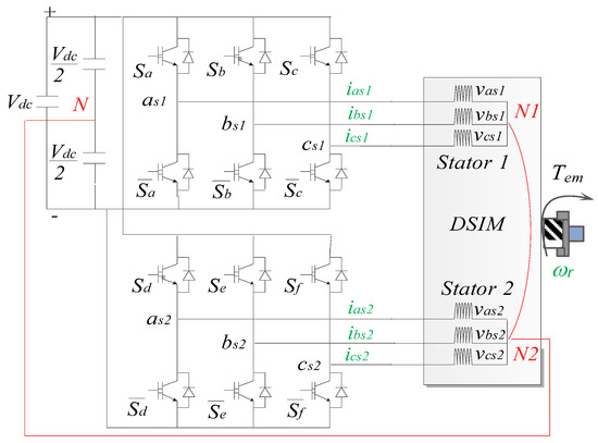
Figure 1.
Scheme of the DSIM drive.
The modeling approach introduces high resistance in series with the faulty phase, which cancels the current and allows for the simulation of faults. Note that, in order to simplify the modeling, the usual assumptions are made (the machine is not saturated, the non-load back electromotive force waveform is sinusoidal, the rotor is non-salient, the winding space harmonics are negligible, and hysteresis and eddy current effects are negligible). Considering the distribution of the phases, the general expression of the stator voltages is:
By introducing magnetic flux, the equation becomes:
being the different inductance matrixes:
The electromagnetic torque and mechanic expression complete the system:
where: is the rotating speed, and is the load torque.
This model presents DSIM considering two three-phase stars, as shown in Figure 2a. Figure 2b shows the DSIM considering three independent two-phase submachines, each one with orthogonal winding.
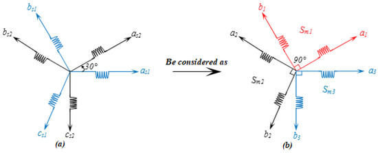
Figure 2.
Model of the DSIM: (a) two three-phase windings and (b) multi-biphase grouping.
The multi-biphase modeling of the multiphase machine requires the coordinate change detailed in (11), which results in (12) from (1).
where: defines the different DSIM variables
The equations of the magnetic flux, with applying variable changing, are given by:
where the inductance matrices can be obtained from Equations (3)–(5) as:
The stator model of the DSIM in the multi-biphase coordinate system is given from (12) and (13) by:
The advantage of using this biphase model in the natural base is the analysis of the behavior of the machine during an OPF. The OPF is obtained by inserting a high-value resistor in series with said phase. During the fault, it is sufficient to disconnect the phase perpendicular to the fault (reconfiguration). As a result, the torque ripples are reduced with acceptable continuation of the service, which makes it possible to protect the rest of the traction chain. This reconfiguration cannot be performed without reconfiguring the voltage inverter.
3. Reconfiguration Strategy for Service Continuation
Several types of faults can appear in an electric drive (Figure 3), including faults in the stator windings, in the drive chain, or in the power supply. Many components in the electrical drive interact with each other so that a fault in one element can cause the total shutdown of the system. In this study, for a DSIM when OPFs appear, the system becomes unbalanced and a high torque ripple appears, which can destruct and affect the continuity of service of the system.
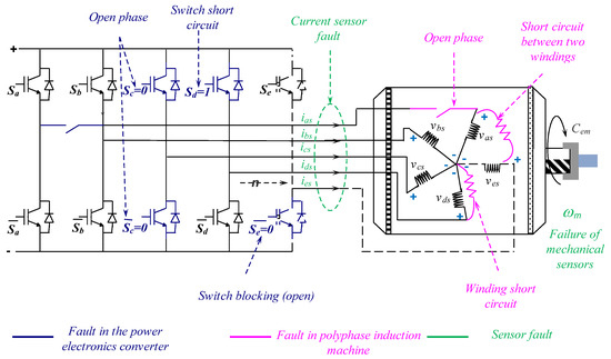
Figure 3.
Different types of faults that appear in a multi-phase drive system.
Interestingly, fault-tolerant OPF strategies are usually based on developing mathematical formulas that model the machine, evaluating new inductance and decoupling matrices. This is achieved using new pre-fault [14,15] or low-order [16,17] transformation matrices and adding equations that model the system uniformly. However, these approaches can skew the results obtained, as they introduce estimation error tolerance in the added formula. From an analytical point of view, it is sometimes convenient to use the model on a natural basis without adding non-real components [18]. Recent research can be divided into two general categories: hardware solutions and software solutions. Hardware solutions are based on neutral point configurations (see [19]) or stator winding connections (see [20,21]). However, the hardware solution always applies to a single OPF and does not provide optimal control of the current, resulting in high losses for electromechanical drives. In contrast, software solutions use specific current control algorithms, such as in [22,23], where fault-tolerant control minimizes torque ripple in one or two open phases and after a fault in the remaining good phases. Then, the most interesting fault-tolerant applications are those that do not need to use complex control algorithms or additional equipment to manage the post-fault operation [24].
The proposed fault-tolerant strategy analyzes three different OPF scenarios, exploiting the multi-biphase modeling of the DSIM to minimize torque ripple and copper losses. Note that the power converter is reconfigured to remove the submachine that corresponds to the OPF. These scenarios are described in what follows.
The first reconfiguration fault scenario (RFS) appears with a single OPF and is based on the cancellation of the stator current in a single submachine. Assuming that the fault appears in the phase, then the stator current is forced to be zero in phase , opening the power switches of the corresponding phase. Note that the and phases are connected to the neutral point N. The obtained stator voltages are given by Equations (18) and (19):
A second RFS happens when two OPFs appear and the stator current of two independent submachines is cancelled. In our case, it will be assumed that this scenario happens when as1 and as2 are opened, and the stator current corresponding to phases cs2 and bs1 are forced to be zero, opening the power switches of the corresponding phases. Then, the multiphase drive operates with a unique submachine, and the obtained stator voltages are given by Equations (20) and (21):
Finally, a third RFS is considered when two (or three) phases in the same stator winding are opened, cancelling the currents of one independent winding. The main consequence in this scenario is that the DSIM operates like a conventional three-phase induction machine, and the obtained stator voltages in the faulty stator winding are === 0.
4. Results Analysis and Discussion of the Proposed OPF Reconfiguration Strategy
To show the validity of the proposed theory, some simulations were performed for three considered configurations (D1, D2, and D3), under the same conditions, using MATLAB/Simulink.
- D1: Opening of a stator phase;
- D2: Opening of two adjacent stator phases (different star);
- D3: Opening of two non-adjacent stator phases (same star).
The DSIM is powered by two voltage source inverters. After the machine is started under normal operating conditions, a nominal load with a torque is applied. At , a stator phase open fault is caused after this time, and depending on the phase and the number of open phases, a reconfiguration is performed at ; a discharge of the DSIM must be performed at the same time as the reconfiguration to avoid overheating of the latter. After the simulation, the following results were obtained.
Results Analysis and Discussion
Figure 4 shows the electromagnetic torque before the fault, during the fault, and after the reconfiguration. This clearly shows that the exaggerated torque ripples generated, which exceeded 30% of the nominal torque, by the introduction of defects have been minimized and brought down to approximately 10% of the nominal torque, thanks to the pertinence of the reconfiguration strategies developed. The minimization of electromagnetic torque ripples directly induces an improvement in the quality of the mechanical power (see Figure 5). In Figure 6, the mechanical speed gives an image of the behavior of the DSIM; during D2, a stall of the machine is looming, which is eliminated directly after the machine discharges. Figure 7, Figure 8 and Figure 9 show the evolution of the machine stator currents from the starting at t = 0 s, to the application of the nominal load torque at t = 1.4 s, to the introduction of the fault at t = 2.3 s, and ends with the reconfiguration of the machine at t = 2.9 s. For the three faults studied, the reconfiguration allows for a reduction in the ripples of the currents; however, the amplitudes of the currents for the faults D2 and D3 remain exaggerated, which obliges us to discharge the machine more.
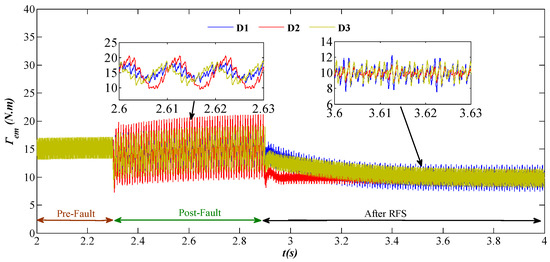
Figure 4.
Electromagnetic torque before and after RFS.
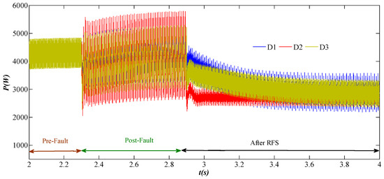
Figure 5.
Mechanical power before and after RFS.
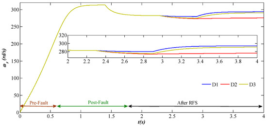
Figure 6.
Electrical speed before and after RFS.
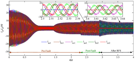
Figure 7.
Stator current before and after RFS for D1.
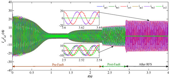
Figure 8.
Stator current before and after RFS for D2.
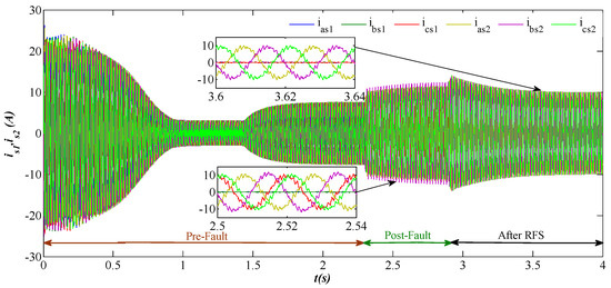
Figure 9.
Stator current before and after RFS for D3.
5. Conclusions
The open-phase fault is a very complex phenomenon that commonly appears in AC machines, and its tolerance is a hard challenge. However, in this paper, a new approach to the fault-tolerant operation of a DSIM under OPF is proposed. The simulation results using MATLAB/Simulink for both the healthy and OFP of DSIM have been presented to justify the validity of the proposed approach. Under OFP, three solutions during post-fault operation are possible, as presented by the reconfiguration strategy. The first RFS was applied when only D1, the second was applied when D2, and the third was applied when D3. Under OPF, the healthy currents become unbalanced and produce high torque ripple magnitude and significant copper losses that affect the lifetime of a drive train. However, by unloading the DSIM to 1/3 of its rated power for the three faults considered, high post-fault currents persist for faults D2 and D3, and in order to avoid winding loss, it is necessary to unload the machine, 2/3 for D2 and 1/2 for D3. The parameter of the double star induction machine are given in Appendix A.
Author Contributions
Methodology, M.-F.B., B.A., K.G. and A.D.; Writing—original draft, K.I. and A.H. All authors have read and agreed to the published version of the manuscript.
Funding
This research received no external funding.
Conflicts of Interest
The authors declare no conflict of interest.
Appendix A
References
- Matsuse, K.; Matsuhashi, D. New Technical Trends on Adjustable Speed AC Motor Drives. Chin. J. Electr. Eng. 2017, 3, 1–9. [Google Scholar]
- Duran, M.J.; Levi, E.; Barrero, F. Multiphase Electric Drives: Introduction. In Wiley Encyclopedia of Electrical and Electronics Engineering; Wiley: Hoboken, NJ, USA, 2017; pp. 1–26. [Google Scholar]
- Barrero, F.; Duran, M. Recent advances in the design, modeling and control of multiphase machines-Part I. IEEE Trans. Ind. Electron. 2016, 63, 449–458. [Google Scholar] [CrossRef]
- Duran, M.; Barrero, F. Recent advances in the design, modeling and control of multiphase machines-Part II. IEEE Trans. Ind. Electron. 2016, 63, 459–468. [Google Scholar] [CrossRef]
- Sarkar, J.; Sun, F.-B.F. Reliability characterization and modeling of solid-state drives. In Proceedings of the 2015 Annual Reliability and Maintainability Symposium (RAMS), Palm Harbor, FL, USA, 26–29 January 2015; pp. 1–6. [Google Scholar]
- Gonçalves, P.; Cruz, S.; Mendes, A. Finite Control Set Model Predictive Control of Six-Phase Asymmetrical Machines—An Overview. Energies 2019, 12, 4693. [Google Scholar] [CrossRef]
- Munim, W.N.W.A.; Che, H.S.; Tousizadeh, M.; Baharom, R.; Muhammad, K.S. Modeling of Six-Phase Induction Machine with Two Isolated Neutrals under One Open Phase Fault. In Proceedings of the 2022 IEEE Industrial Electronics and Applications Conference (IEACon), Kuala Lumpur, Malaysia, 3–4 October 2022; pp. 99–104. [Google Scholar]
- Melo, V.F.M.B.; da Paz, G.F.; de Freitas, I.S. vv-DTC for Healthy and Faulty Operation of an Asymmetrical Six-Phase Induction Machine Drive System With Single Neutral. In Proceedings of the 2021 Brazilian Power Electronics Conference (COBEP), João Pessoa, Brazil, 7–10 November 2021; pp. 1–8. [Google Scholar]
- Munim, W.N.W.A.; Duran, M.J.; Che, H.S.; Bermudez, M.; Gonzalez-Prieto, I.; Rahim, N.A. A unified analysis of the fault tolerance capability in six-phase induction motor drives. IEEE Trans. Power Electron. 2017, 32, 7824–7836. [Google Scholar] [CrossRef]
- Gonzalez-Prieto, I.; Duran, M.J.; Barrero, F.; Bermudez, M.; Guzman, H. Impact of postfault flux adaptation on six-phase induction motor drives with parallel converters. IEEE Trans. Power Electron. 2017, 32, 515–528. [Google Scholar] [CrossRef]
- Baneira, F.; Doval-Gandoy, J.; Yepes, A.G.; López, Ó.; Pérez-Estévez, D. Control strategy for multiphase drives with minimum losses in the full torque operation range under single open-phase fault. IEEE Trans. Power Electron. 2017, 32, 6275–6285. [Google Scholar] [CrossRef]
- Baneira, F.; Doval-Gandoy, J.; Yepes, A.G.; López, Ó.; Pérez-Estévez, D. Comparison of postfault strategies for current reference generation for dual three-phase machines in terms of converter losses. IEEE Trans. Power Electron. 2017, 32, 8243–8246. [Google Scholar] [CrossRef]
- Gonzalez-Prieto, I.; Duran, M.J.; Barrero, F. Fault-tolerant control of six-phase induction motor drives with variable current injection. IEEE Trans. Power Electron. 2017, 32, 7894–7903. [Google Scholar] [CrossRef]
- Che, H.S.; Duran, M.J.; Levi, E.; Jones, M.; Hew, W.P.; Rahim, N.A. Post fault operation of an asymmetrical six-phase induction machine with single and two isolated neutral points. IEEE Trans. Power Electron. 2014, 29, 5406–5416. [Google Scholar] [CrossRef]
- Tani, A.; Mengoni, M.; Zarri, L.; Serra, G.; Casadei, D. Control of multiphase induction motors with an odd number of phases under open-circuit phase faults. IEEE Trans. Power Electron. 2012, 27, 565–577. [Google Scholar] [CrossRef]
- Guzmán, H.; Duran, J.; Barrero, F.; Bogado, B.; Toral, S. Speed control of five-phase induction motors with integrated open-phase fault operation using model-based predictive current control techniques. IEEE Trans. Ind. Electron. 2014, 61, 4474–4484. [Google Scholar] [CrossRef]
- Kianinezhad, R.; Nahid-Mobarakeh, B.; Baghli, L.; Betin, F.; Capolino, G.A. Modeling and control of six-phase symmetrical induction machine under fault condition due to open phases. IEEE Trans. Ind. Electron. 2008, 55, 1966–1977. [Google Scholar] [CrossRef]
- Vukosavic, S.N.; Jones, M.; Levi, E.; Varga, J. Rotor flux oriented control of a symmetrical six-phase induction machine. Electr. Power Syst. Res. 2005, 75, 142–152. [Google Scholar] [CrossRef]
- Hisham, M.E.; Abdel-Khalik, A.S.; Christoph, M.H. Post-fault full torque-speed exploitation of dual three-phase IPMSM drives. IEEE Trans. Ind. Electron. 2019, 66, 6746–6756. [Google Scholar]
- Abdel-Khalik, A.S.; Morsy, A.; Ahmed, S.; Massoud, A. Effect of stator winding connection on performance of five-phase induction machines. IEEE Trans. Ind. Electron. 2014, 61, 3–19. [Google Scholar] [CrossRef]
- Abdel-Khalik, A.S.; Ahmed, S.; Massoud, A. Post fault operation of a nine-phase six terminal induction machine under single open line fault. IEEE Trans. Ind. Electron. 2017, 65, 1084–1096. [Google Scholar] [CrossRef]
- Tamires, S.S.; Rodrigo, R.B.; Braz, J.C. Modeling and control of a nine-phase induction machine with open phase. IEEE Trans. Ind. Appl. 2018, 54, 6576–6585. [Google Scholar]
- Fu, J.R.; Lipo, T.A. Disturbance free operation of a multiphase current regulated motor drive with an opened phase. IEEE Trans. Ind. Appl. 1994, 30, 1267–1274. [Google Scholar]
- Iffouzar, K.; Amrouche, B.; Cherif, T.O.; Benkhoris, M.-F.; Aouzellag, D.; Ghedamsi, K. Improved direct field oriented control of multiphase induction motor used in hybrid electric vehicle application. Int. J. Hydrogen Energy 2017, 42, 19296–19308. [Google Scholar] [CrossRef]
Disclaimer/Publisher’s Note: The statements, opinions and data contained in all publications are solely those of the individual author(s) and contributor(s) and not of MDPI and/or the editor(s). MDPI and/or the editor(s) disclaim responsibility for any injury to people or property resulting from any ideas, methods, instructions or products referred to in the content. |
© 2023 by the authors. Licensee MDPI, Basel, Switzerland. This article is an open access article distributed under the terms and conditions of the Creative Commons Attribution (CC BY) license (https://creativecommons.org/licenses/by/4.0/).