The Influence of Electric Arc Plasma Turbulence on Heat Transfer Processes Involving Powder Materials
Abstract
1. Introduction
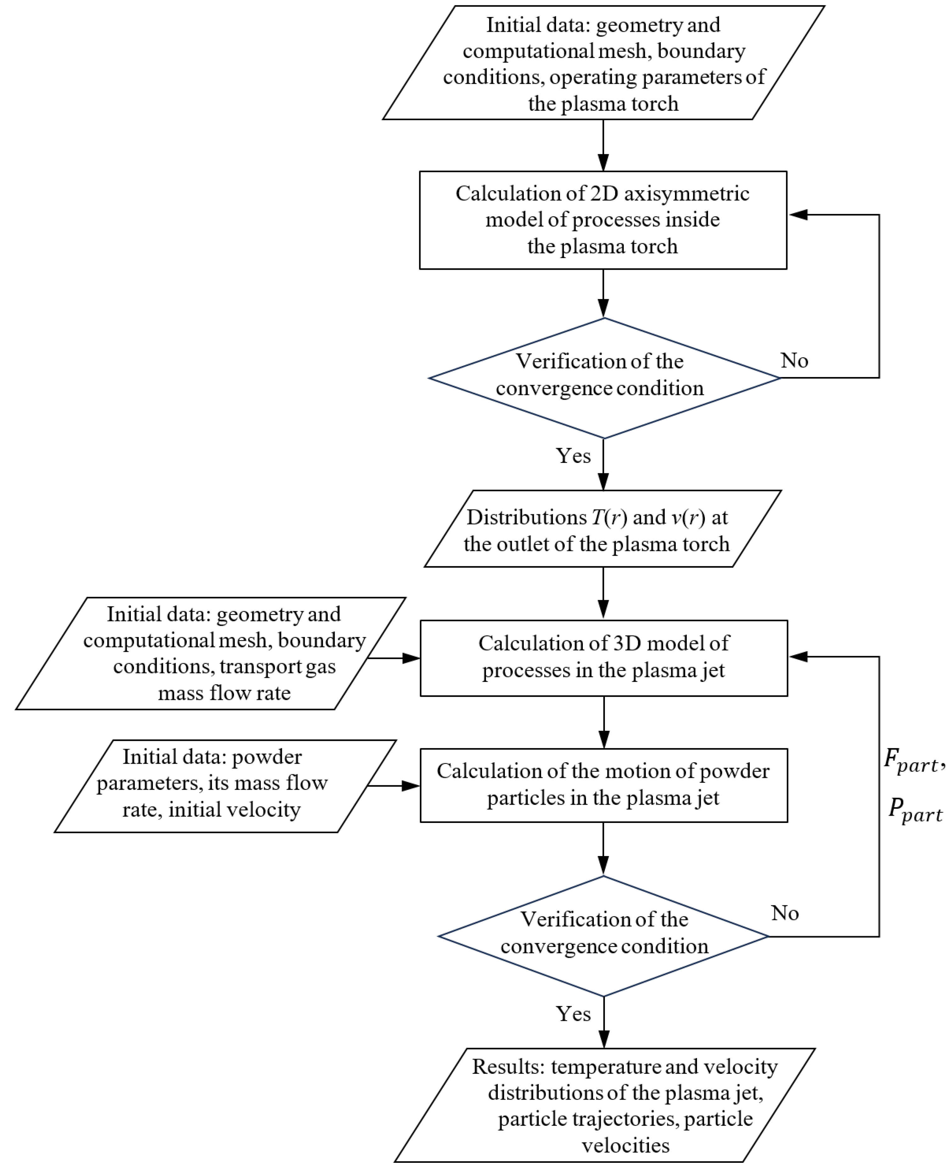
2. Mathematical Model of Powder Motion in a Plasma Jet
- –
- Energy equation:where is the velocity, is the density, h is the enthalpy related to the temperature T, is the thermal conductivity, and is a source term for the energy equation.
- –
- Motion equation:where p is the static pressure, is the stress tensor, is the acceleration of gravity, and is the electromagnetic force.
- –
- Continuity equation:
- –
- The equations of the electromagnetic task for the magnetic vector potential and the electric scalar potential were obtained from the system of the electromagnetic equations of Maxwell [32]:
- – Energy equation for a particle:
- –
- Motion equation for a particle:where is the particle velocity, is the particle density, and is the drag force defined by the following expression:
- –
- Energy equation for the plasma:where is the power losses for the plasma due to the powder heating. In the conditions of the plasma jet, the source term takes into account only the power losses due to radiation:
- –
- Motion equation for the plasma:where is the momentum losses for the plasma due to the powder acceleration.
- –
- Continuity equation for the plasma:
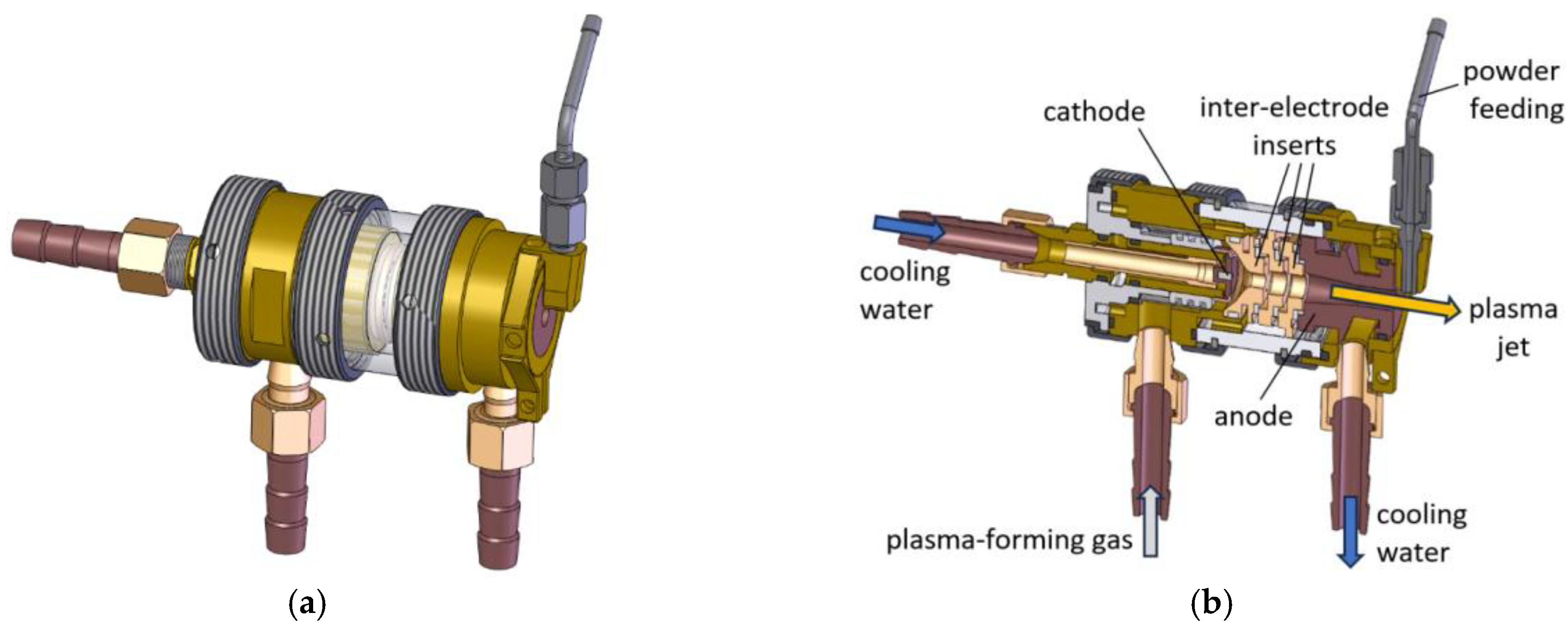
- The nozzle diameter was 6 mm and the charge pipeline diameter was 1.6 mm;
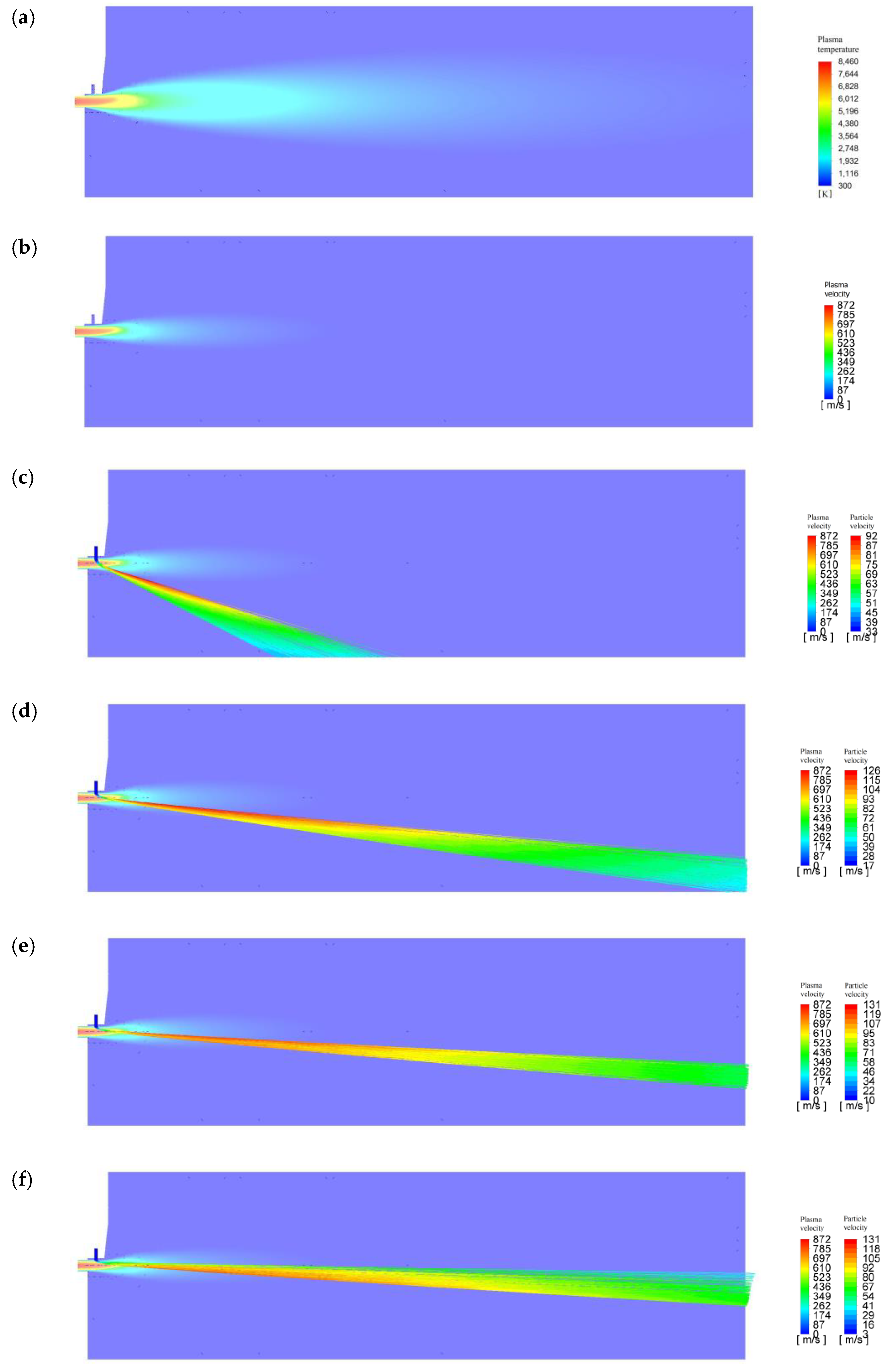
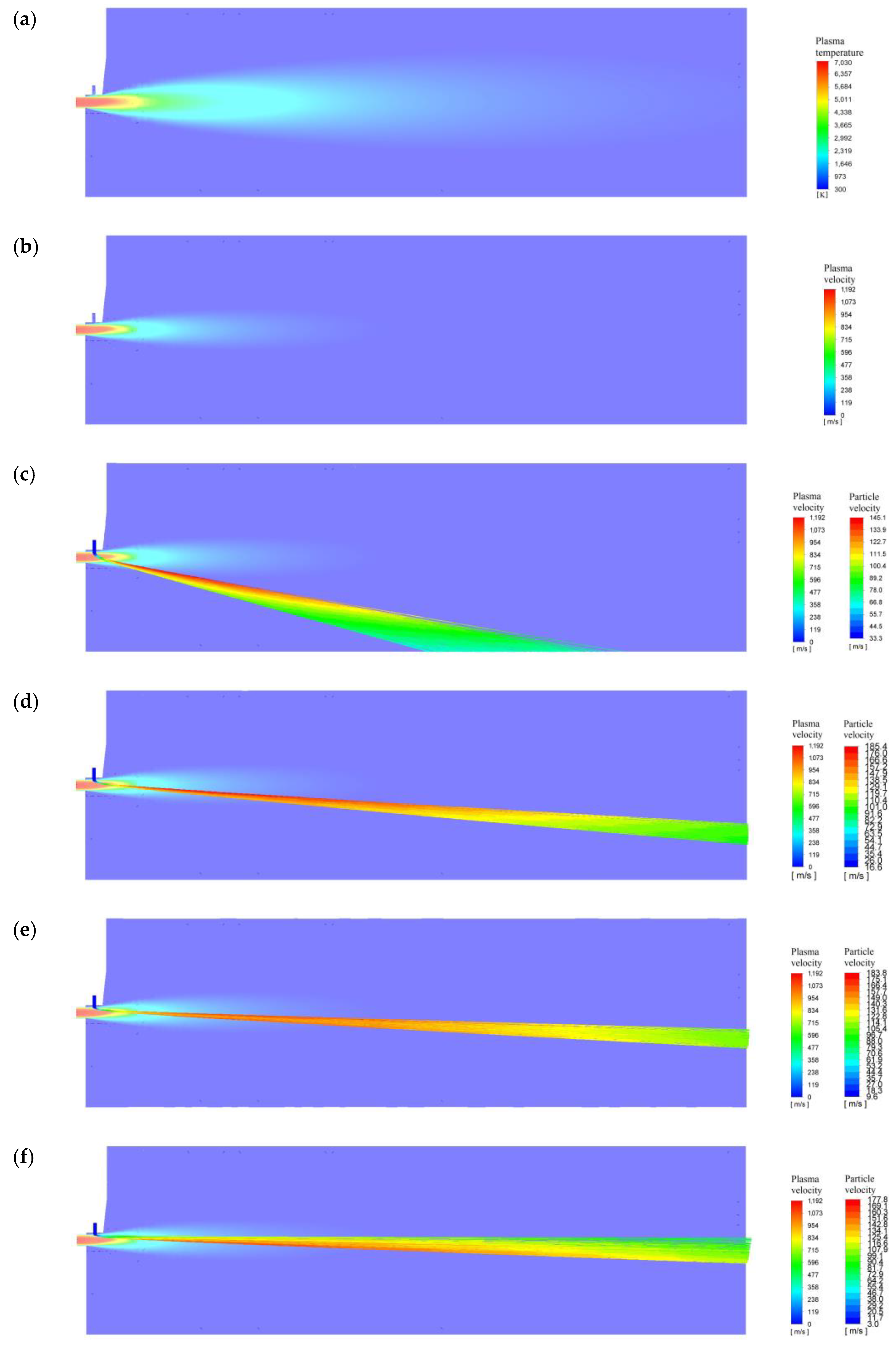
- The flow rate of the plasma-forming gas (air) was 0.75 g/s; 1.0 g/s; and 1.4 g/s;
- The transporting gas flow rate was 0.08 g/s (which corresponds to an initial velocity through a charge pipeline of 34.5 m/s); the powder consumption was 0.07 g/s; and the powder material was aluminum with a powder diameter of 50–60 microns and an average diameter of 55 microns;
- The initial velocity of the powder varied from 3 m/s to 34.5 m/s.
3. Influence of the Turbulent Nature of the Plasma-Forming Gas on the Heat Transfer between the Thermal Energy of the Plasma and the Powder Material
4. Laboratory Experiment to Determine the Effect of the Plasma Jet Turbulence Degree on the Intensity of Heating of the Particles of the Sprayed Material
- , the mass flow rate of the powder, then the velocity of the powder is in the range from 10 to 100 m/s;
- , the mass flow rate of the plasma-forming gas, then the gas velocity is in the range from 50 to 200 m/s;
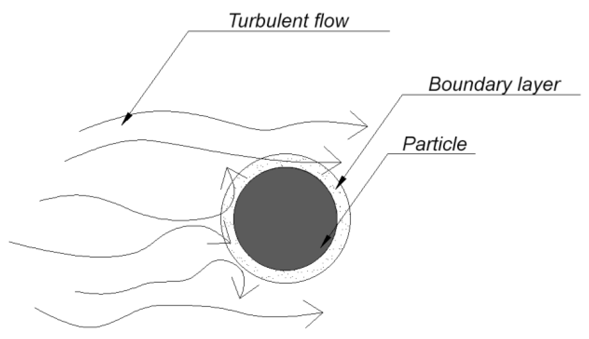
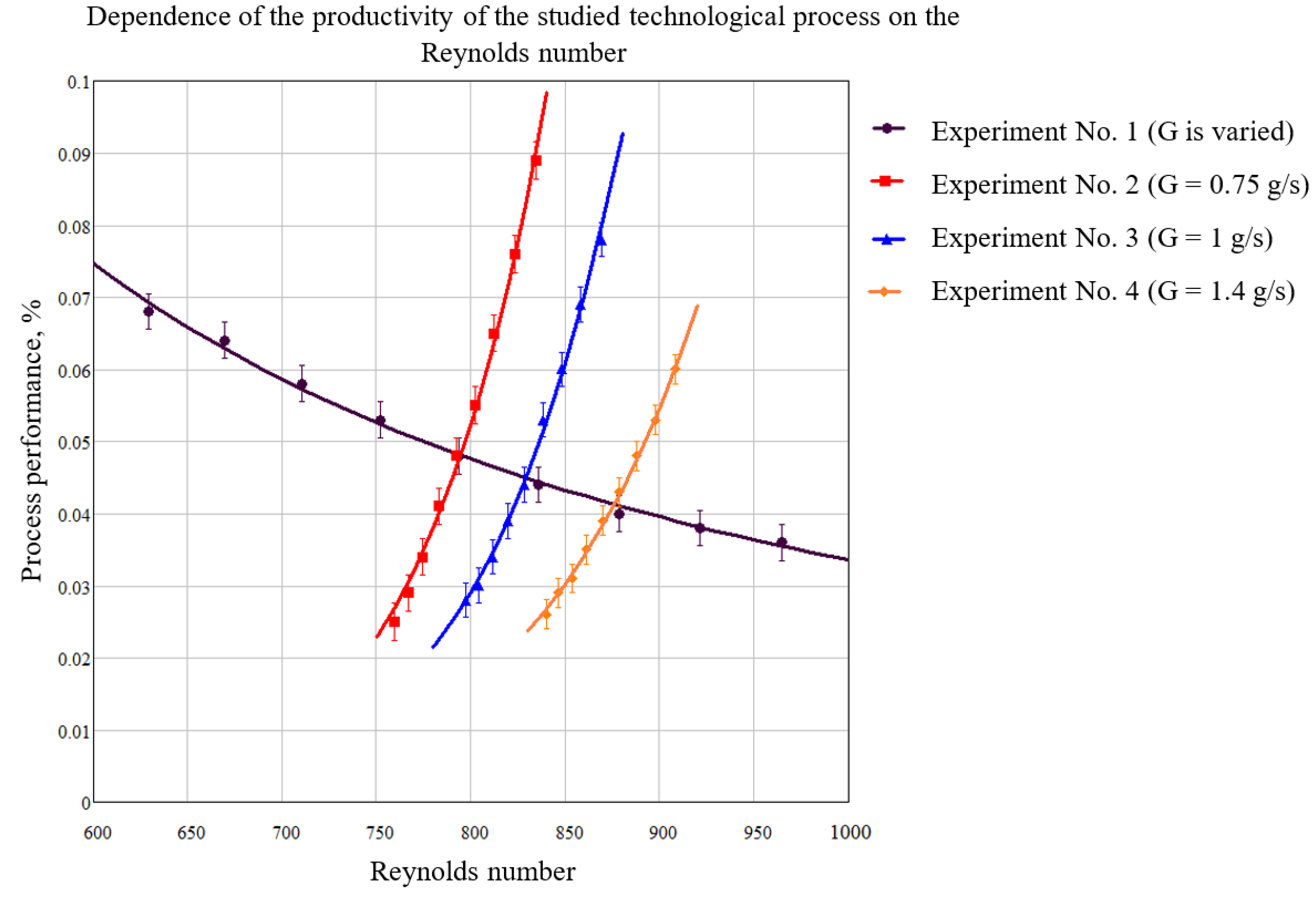
- The Reynolds number Re (respectively, the nature of the flow of the gaseous medium under consideration) is a calculated parameter for each case, and has a significant impact on the value of the parameter α;
- The arc current is in the range from 100 to 200 A.
- A constant spraying time;
- A constant value of the power in the experiments on the study of laminar and turbulent flows;
- The Prandtl number .
5. Conclusions
Author Contributions
Funding
Data Availability Statement
Conflicts of Interest
Nomenclature
| Latin Symbols | |
| magnetic vector potential | |
| magnetic induction | |
| specific heat | |
| specific heat of the particle material | |
| diameter of the nozzle | |
| diameter of the particle | |
| electric field intensity | |
| electromagnetic force | |
| drag force | |
| momentum losses for plasma due to powder acceleration | |
| mass flow rate of the plasma forming gas | |
| mass rate of powder feeding | |
| acceleration of gravity | |
| h | enthalpy |
| arc current | |
| current density | |
| kjet | empirical coefficient that determines the fraction of input power that is carried out by the plasma jet |
| length of the thermal active zone of the plasma jet | |
| distance to the surface of the workpiece | |
| particle mass | |
| mass of the substrate before spraying | |
| mass of the substrate after spraying | |
| increase in the mass of the substrate after coating | |
| Nu | Nusselt number, |
| the total electric power expended | |
| source term for energy equation | |
| power losses for plasma due to powder heating | |
| plasma jet power expended to heat the powder | |
| p | static pressure |
| Pr | Prandtl number |
| Re | Reynolds number |
| area of the inlet section | |
| surface area of the particle | |
| area of the powder feeding tube | |
| T | temperature |
| average mass temperature of the plasma arc | |
| particle temperature | |
| difference between plasma temperature and particle temperature | |
| time of spraying operation | |
| arc voltage | |
| power losses due to radiation | |
| velocity | |
| plasma velocity at the outlet of the nozzle | |
| particle velocity | |
| initial velocities of particles | |
| powder velocity | |
| relative velocity of powder | |
| axial velocity at the inlet | |
| process performance | |
| Greek Symbols | |
| convective heat transfer coefficient | |
| dynamic boundary layer | |
| temperature boundary layer | |
| particle emissivity | |
| efficiency | |
| technological efficiency | |
| thermal conductivity | |
| plasma thermal conductivity averaged over the boundary layer | |
| μ | dynamic viscosity of the plasma |
| density | |
| particle density | |
| electrical conductivity | |
| Stefan–Boltzmann constant | |
| the stress tensor | |
| electric scalar potential | |
| Subscripts | |
| part | particle |
| in | inlet |
| n | nozzle |
| spr | spraying |
| sub | substrate |
| ave | average |
| w | workpiece |
References
- Kudinov, V.V.; Bobrov, G.V. Application of coatings by Spraying. Theory, Technology and Equipment; Metallurgy: Moscow, Russia, 1992; 432p. [Google Scholar]
- Frolov, V.Y.; Klubnikin, V.S.; Petrov, G.K.; Yushin, B.A. Technique and Technology of Coatings Application; Polytechnic University Publishing House: St. Petersburg, Russia, 2008; 307p. [Google Scholar]
- Frolov, V.Y.; Dresvin, S.V.; Lisenkov, A.A.; Ivanov, V.N.; Zverev, S.G.; Ivanov, D.V.; Petrov, G.K.; Yushin, B.A.; Smorodinov, V.V.; Veselovsky, A.P. Electrotechnological Industrial Installations; Frolov, V.Y., Ed.; Polytechnic University Publishing House: St. Petersburg, Russia, 2010; 571p. [Google Scholar]
- Zhukov, M.F.; An'shakov, A.S.; Zasypkin, I.M.; Mishne, I.I.; Sazonov, M.I. Heat transfer investigation from turbulent electric arc to wall at film cooling. In Proceedings of the Twelfth International Conference on Phenomena in Ionized Gases, Eindhoven, The Netherlands, 18–22 August 1975; Volume I; p. 201. [Google Scholar]
- Tsvetkov, Y.V. Plasma processes in metallurgy. In Thermal Plasma and New Materials Technology; Cambridge Interscience Publishing: Cambridge, UK, 1995; Volume 2, pp. 291–322. [Google Scholar]
- Frolov, V.; Petrov, G.; Yushin, B.; Ivanov, D.; Zverev, S. Air-plasma technologies of spraying of coatings. In Proceedings of the VII International Conference on Plasma Physics and Plasma Technology, Minsk, Belarus, 17–21 September 2012; pp. 608–611. [Google Scholar]
- Heberlein, J.V.R.; Ohtake, N. Plasma torch diamond deposition. In Diamond Films Handbook; Asmussen, J., Reinhard, D.K., Eds.; CRC Press: Boca Raton, FL, USA, 2002; Chapter 6; pp. 141–210. [Google Scholar]
- Lima, R.S.; Li, H.; Khor, K.A.; Marple, B.R. Biocompatible Nanostructured High-Velocity Oxyfuel Sprayed Titania Coating: Deposition, Characterization and Mechanical Properties. J. Therm. Spray Technol. 2006, 15, 623–627. [Google Scholar] [CrossRef]
- Trelles, J.P.; Pfender, E.; Heberlein, J.V.R. 3D Finite Element Modeling of Arc and Jet Dynamics in a DC Plasma Torch. In Proceedings of the APS—2006 59th Annual Gaseous Electronics Conference, Columbus, OH, USA, 10–13 October 2006; p. 45. [Google Scholar]
- Duan, Z.; Heberlein, J.V.R. Arc instabilities in a plasma spray torch. J. Therm. Spray Technol. 2002, 11, 44–51. [Google Scholar] [CrossRef]
- Coudert, J.F.; Fauchais, P. Arc instabilities in a D. C. plasma torch. High Temp. Mater. Processes 1997, 1, 149–166. [Google Scholar] [CrossRef]
- Coudert, J.F.; Planche, M.P.; Fauchais, P. Characterization of D.C. plasma torch voltage fluctuations. Plasma Chem. Plasma Proc. 1996, 16, 211s–227s. [Google Scholar] [CrossRef]
- Gonzales, J.J.; Freton, P.; Gleizes, A. Comparisons between two- and three-dimensional models: Gas injection and arc attachment. J. Phys. D: Appl. Phys. 2002, 35, 3181–3191. [Google Scholar] [CrossRef]
- Frolov, V.; Ivanov, D.; Toropchin, A. Analysis of processes in dc arc plasma torches for spraying that use air as plasma forming gas. J. Phys. Conf. Ser. 2014, 550, 012021. [Google Scholar] [CrossRef]
- Hoseinzadeh, S.; Heyns, P.S.; Kariman, H. Numerical investigation of heat transfer of laminar and turbulent pulsating Al2O3/water nanofluid flow. Int. J. Numer. Methods Heat Fluid Flow 2019, 30, 1149–1166. [Google Scholar] [CrossRef]
- Ghasemi, M.H.; Hoseinzadeh, S.; Memon, S. A dual-phase-lag (DPL) transient non-Fourier heat transfer analysis of functional graded cylindrical material under axial heat flux. Int. Commun. Heat Mass Transf. 2022, 131, 105858. [Google Scholar] [CrossRef]
- Ievlev, V.M.; Son, E.E. Turbulence of low-temperature plasma in a magnetic field. In Proceedings of the Seventh All-Union Conference on the Physics of Low-Temperature Plasma, Moscow, Russia, 19–22 May 1987; pp. 89–96. [Google Scholar]
- Tsytovich, V.N. Theory of Turbulent Plasma; Atomizdat: Moscow, Russia, 1971; 425p. [Google Scholar]
- Huang, R.; Fukanuma, H.; Uesugi, Y.; Tanaka, Y. Simulation of Arc Root Fluctuation in a DC Non-Transferred Plasma Torch with Three Dimensional Modeling. J. Therm. Spray Technol. 2012, 21, 636–643. [Google Scholar] [CrossRef]
- Li, H.; Chen, X. Three-dimensional modeling of the turbulent plasma jet impinging upon a flat plate and with transverse particle and carrier-gas injection. Plasma Chem. Plasma Proc. 2002, 22, 27–58. [Google Scholar] [CrossRef]
- Baeva, M.; Gorchakov, S.; Kozakov, R.; Uhrlandt, D.; Schoenemann, T. Non-equilibrium modeling of the electrical characteristics of a freeburning. High Volt. Eng. 2013, 39, 2159–2165. [Google Scholar]
- Tradia, A. Multiphysics Modeling and Numerical Simulation of GTA Weld Pools. Ph.D. Thesis, Ecole Polytechnique, Paris, France, 2011; 224p. [Google Scholar]
- Trelles, J.P.; Chazelas, C.; Vardelle, A.; Heberlein, J.V.R. Arc plasma torch modeling. J. Therm. Spray Technol. 2009, 18, 728–752. [Google Scholar] [CrossRef]
- Colombo, V.; Concetti, A.; Ghedini, E. Time dependent 3D large eddy simulation of a DC non-transferred arc plasma spraying torch with particle injections. In Proceedings of the 2007 16th IEEE International Pulsed Power Conference, Albuquerque, NM, USA, 17–22 June 2007; Volume 2, pp. 1565–1568. [Google Scholar]
- Delalondre, C.; Simonin, O. Turbulence modeling in electric arcs. In Heat and Mass Transfer Under Plasma Conditions; Begell House: New York, NY, USA, 1995; pp. 1–15. [Google Scholar]
- Frolov, V.Y.; Uhrlandt, D.; Lisenkov, A.A. Physics and Diagnostics of Non-Equilibrium Plasma. Fundamentals of the Theory of Near-Electrode Processes of Arc Discharge; Publishing House of the Polytechnic University: St. Petersburg, Russia, 2013; 198p. [Google Scholar]
- Yun, A.A. Theory and Practice of Modeling Turbulent Flows; Librokom: Moscow, Russia, 2009; 272p. [Google Scholar]
- Murashov, Y.V. Development of an Arc Plasma Torch for Spraying Taking into Account the Phenomena of Instability of the Plasma Flow. Ph.D. Thesis, Peter the Great St. Petersburg Polytechnic University, St. Petersburg, Russia, 2016; 22p. [Google Scholar]
- Frolov, V.; Murashov, I.; Ivanov, D. Special aspects of dc air plasma torch’s operating modes under turbulent flow conditions. Plasma Phys. Technol. J. 2015, 2, 129–133. [Google Scholar]
- Murashov, I.; Frolov, V.; Ivanov, D. Numerical simulation of DC air plasma torch modes and plasma jet instability for spraying technology. In Proceedings of the 2016 IEEE NW Russia Young Researchers in Electrical and Electronic Engineering Conference (EIConRusNW), St. Petersburg, Russia, 2–3 February 2016; pp. 625–628. [Google Scholar]
- ANSYS Fluent Theory Guide. Available online: https://ansyshelp.ansys.com (accessed on 30 May 2023).
- Boulos, M.I.; Fauchais, P.L.; Pfender, E. Handbook of Thermal Plasmas; Springer International Publishing: Cham, Switzerland, 2023; 1973p. [Google Scholar]
- ANSYS Fluent UDF Manual. Available online: https://ansyshelp.ansys.com (accessed on 30 May 2023).
- Dresvin, S.V.; Ivanov, D.V. Plasma Physics; Polytechnic University Publishing House: St. Petersburg, Russia, 2013; 544p. [Google Scholar]
- Derevyankin, P.G.; Kriskovets, D.S.; Frolov, V.Y.; Yushin, B.A. Analysis of the electrophysical and thermophysical properties of copper-graphite material for arcing contacts of a high-current low-voltage circuit breaker. In Proceedings of the 2021 IEEE Conference of Russian Young Researchers in Electrical and Electronic Engineering (ElConRus), St. Petersburg, Russia, 26–29 January 2021; pp. 839–843. [Google Scholar]
- Baldaev, L.K.; Borisov, V.N.; Vakhalin, V.A.; Gannochenko, G.I.; Zatoka, A.E.; Zakharov, B.M.; Ivanov, A.V.; Ivanov, V.M.; Kalita, V.I.; Kudinov, V.V.; et al. Gas-Thermal Spraying; Baldaev, L.K., Ed.; Market DS: Moscow, Russia, 2007; 344p. [Google Scholar]
- Dresvin, S.V.; Zverev, S.G. Heat Transfer in Plasma; Polytechnic University Publishing House: St. Petersburg, Russia, 2008; 212p. [Google Scholar]
- Amouroux, J.; Morvan, D.; Ouvrelle, L.; Dresvin, S.; Ivanov, D.; Zverev, S.; Feigenson, O.; Balashov, A. Calculation of silicon particles dynamics, heat and mass transfers in thermal plasmas. Effect of particles vaporization. High Temp. Mat. Proc. 2003, 7, 93–105. [Google Scholar] [CrossRef]




| Boundary (See Figure 4) | Physical Quantity | ||||||
|---|---|---|---|---|---|---|---|
| T | p | ||||||
| AB | 0 | 0 | – | ||||
| BC | 300 K | 0 | – | ||||
| CD, DE | 300 K | 0 | 0 | – | |||
| EF | 300 K | 0 | 0 | – | |||
| FG | 1 atm | 0 | 0 | ||||
| GH | 1 atm | ||||||
| AH | 0 | – | |||||
| DL | – | – | – | – | – | – | 0 |
| Plasma Parameters | Plasma-Forming Gas Flow Rate, g/s | ||
|---|---|---|---|
| 0.75 | 1.0 | 1.4 | |
| Maximum plasma temperature, K | 8460 | 7030 | 6656 |
| Maximum plasma velocity, m/s | 872 | 1192 | 1414 |
| Initial Velocity, m/s | Plasma-Forming Gas Flow Rate, g/s | ||
|---|---|---|---|
| 0.75 | 1.0 | 1.4 | |
| 3 | 131 | 178 | 201 |
| 5 | 131 | 179 | 203 |
| 10 | 131 | 184 | 211 |
| 17 | 126 | 185 | 219 |
| 34.5 | 92.5 | 145 | 182 |
| Technological Process Parameters | ||
|---|---|---|
| Distance to the surface of the workpiece | , l, mm | 350 |
| Operating electrical power | , W | 24,000 |
| Average plasma temperature | , K | 6000 |
| Spraying time | , s | 8 |
| , g/s | , m/s | , g | , g | , g | W, g/s | , m/s | Re | , % |
|---|---|---|---|---|---|---|---|---|
| 0.500 | 103.821 | 81.390 | 82.062 | 0.672 | 0.084 | 125.215 | 551.234 | 84.00 |
| 0.550 | 114.203 | 101.114 | 101.706 | 0.592 | 0.074 | 133.949 | 589.684 | 74.00 |
| 0.600 | 124.585 | 103.820 | 104.364 | 0.544 | 0.068 | 142.903 | 629.105 | 68.00 |
| 0.650 | 134.967 | 109.430 | 109.941 | 0.511 | 0.064 | 152.040 | 669.326 | 64.00 |
| 0.700 | 145.349 | 103.190 | 103.653 | 0.463 | 0.058 | 161.327 | 710.210 | 58.00 |
| 0.750 | 155.731 | 101.210 | 101.632 | 0.422 | 0.053 | 170.740 | 751.650 | 53.00 |
| 0.800 | 166.113 | 105.790 | 106.175 | 0.385 | 0.048 | 180.260 | 793.559 | 48.00 |
| 0.850 | 176.495 | 103.760 | 104.110 | 0.350 | 0.044 | 189.870 | 835.866 | 44.00 |
| 0.900 | 186.877 | 103.920 | 104.243 | 0.323 | 0.040 | 199.557 | 878.513 | 40.00 |
| 0.950 | 197.259 | 105.670 | 105.976 | 0.306 | 0.038 | 209.311 | 921.453 | 38.00 |
| 1.000 | 207.641 | 103.190 | 103.478 | 0.288 | 0.036 | 219.123 | 964.648 | 36.00 |
| Al, % | , g/s | , m/s | , g | , g | , g | W, g/s | , g/s | Re | , % |
|---|---|---|---|---|---|---|---|---|---|
| 100.000 | 0.050 | 46.531 | 106.308 | 106.510 | 0.202 | 0.025 | 172.507 | 759.430 | 50.00 |
| 93.750 | 0.056 | 52.255 | 107.124 | 107.354 | 0.230 | 0.029 | 174.138 | 766.611 | 51.79 |
| 87.500 | 0.063 | 57.951 | 110.026 | 110.298 | 0.272 | 0.034 | 175.931 | 774.505 | 53.97 |
| 81.250 | 0.069 | 63.615 | 104.110 | 104.440 | 0.330 | 0.041 | 177.877 | 783.072 | 59.42 |
| 75.000 | 0.075 | 69.243 | 106.102 | 106.482 | 0.380 | 0.048 | 179.967 | 792.271 | 64.00 |
| 68.750 | 0.081 | 74.831 | 108.666 | 109.106 | 0.440 | 0.055 | 182.190 | 802.057 | 67.90 |
| 62.500 | 0.088 | 80.373 | 101.380 | 101.903 | 0.523 | 0.065 | 184.536 | 812.383 | 73.86 |
| 56.250 | 0.094 | 85.863 | 103.881 | 104.491 | 0.610 | 0.076 | 186.992 | 823.197 | 80.85 |
| 50.000 | 0.1 | 91.293 | 103.490 | 104.260 | 0.710 | 0.089 | 189.547 | 834.443 | 89.00 |
Disclaimer/Publisher’s Note: The statements, opinions and data contained in all publications are solely those of the individual author(s) and contributor(s) and not of MDPI and/or the editor(s). MDPI and/or the editor(s) disclaim responsibility for any injury to people or property resulting from any ideas, methods, instructions or products referred to in the content. |
© 2023 by the authors. Licensee MDPI, Basel, Switzerland. This article is an open access article distributed under the terms and conditions of the Creative Commons Attribution (CC BY) license (https://creativecommons.org/licenses/by/4.0/).
Share and Cite
Petrenya, Y.K.; Frolov, V.Y.; Kriskovets, D.S.; Yushin, B.A.; Ivanov, D.V. The Influence of Electric Arc Plasma Turbulence on Heat Transfer Processes Involving Powder Materials. Energies 2023, 16, 5632. https://doi.org/10.3390/en16155632
Petrenya YK, Frolov VY, Kriskovets DS, Yushin BA, Ivanov DV. The Influence of Electric Arc Plasma Turbulence on Heat Transfer Processes Involving Powder Materials. Energies. 2023; 16(15):5632. https://doi.org/10.3390/en16155632
Chicago/Turabian StylePetrenya, Yuri K., Vladimir Ya. Frolov, Dmitriy S. Kriskovets, Boris A. Yushin, and Dmitriy V. Ivanov. 2023. "The Influence of Electric Arc Plasma Turbulence on Heat Transfer Processes Involving Powder Materials" Energies 16, no. 15: 5632. https://doi.org/10.3390/en16155632
APA StylePetrenya, Y. K., Frolov, V. Y., Kriskovets, D. S., Yushin, B. A., & Ivanov, D. V. (2023). The Influence of Electric Arc Plasma Turbulence on Heat Transfer Processes Involving Powder Materials. Energies, 16(15), 5632. https://doi.org/10.3390/en16155632


