

A Review on the Cost Analysis of Hydrogen Gas Storage Tanks for Fuel Cell Vehicles


Abstract
1. Introduction
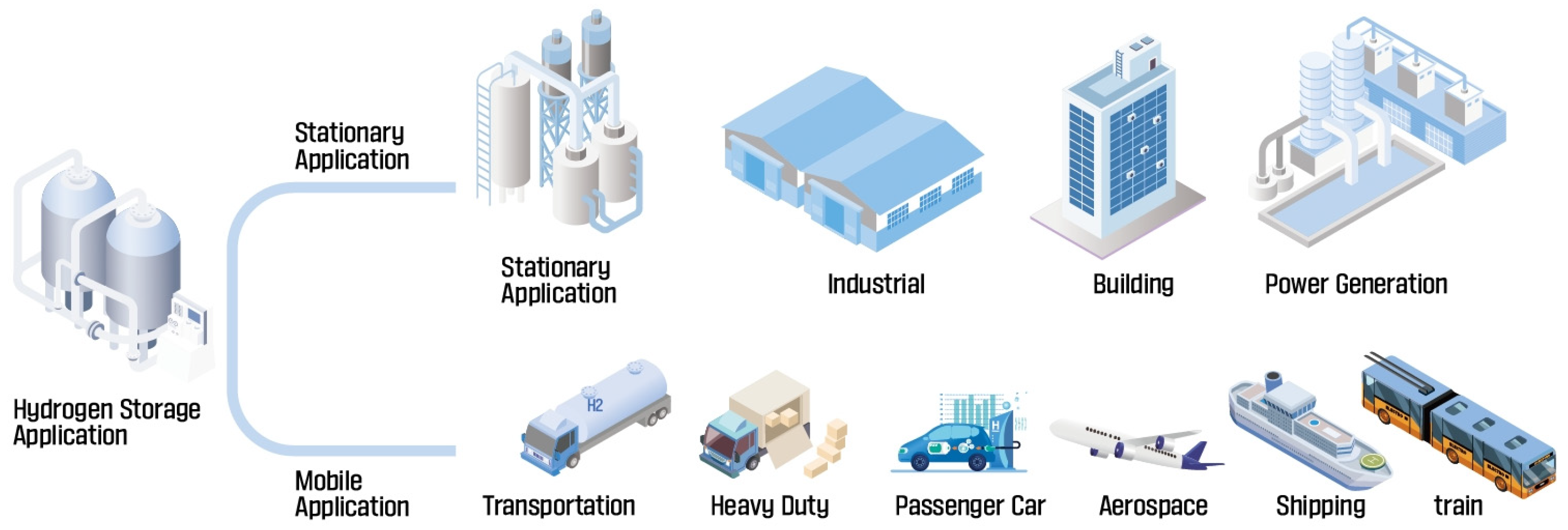
2. Application of Hydrogen Storage Tanks
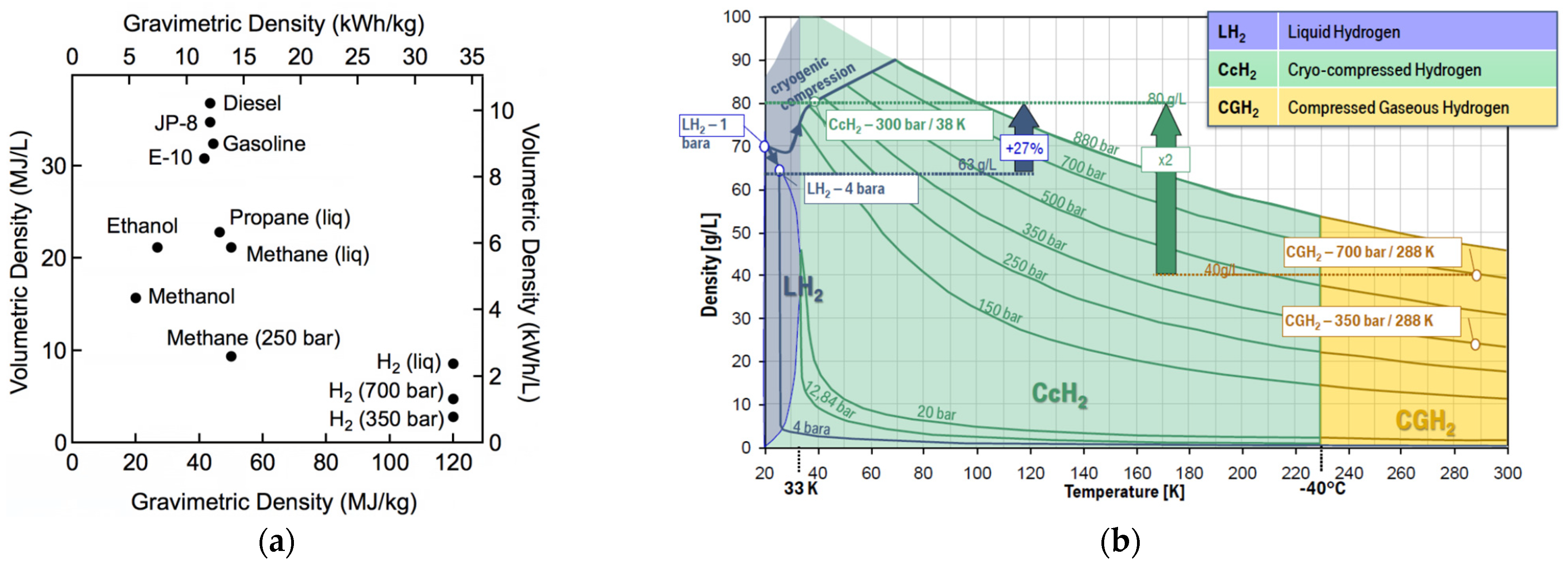
2.1. Hydrogen Storage Systems

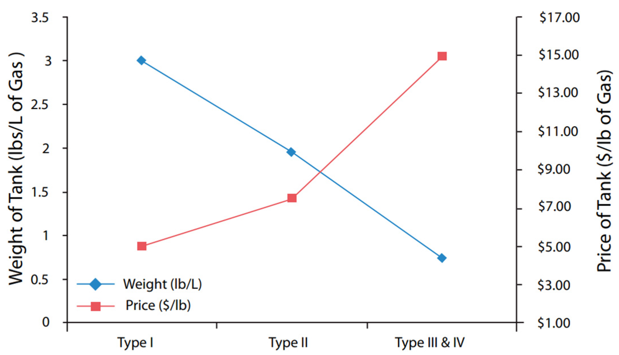
2.2. Types of Hydrogen Storage Tanks
- Type I: All metal construction;
- Type II: Metal with hoop composite overwrap;
- Type III: Metal liner with full composite overwrap. Composite carries all load;
- Type IV: Polymer liner with a full composite overwrap;
- Type V: Linerless composite vessels.
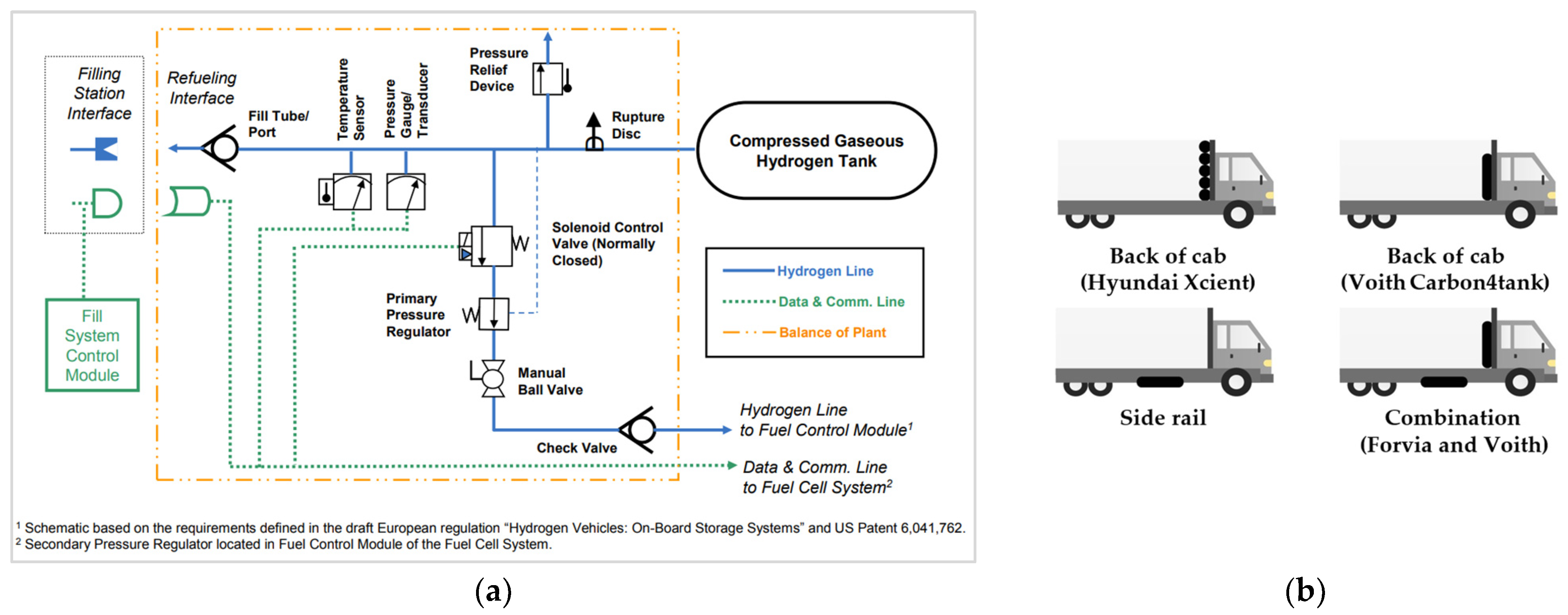
2.3. On-Road Application
3. Cost and Cost Modeling
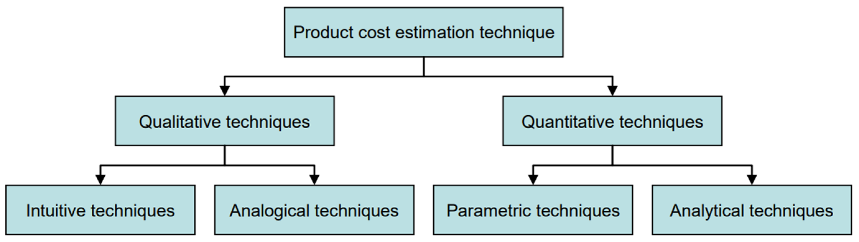
3.1. Definition of Cost and Cost Modeling
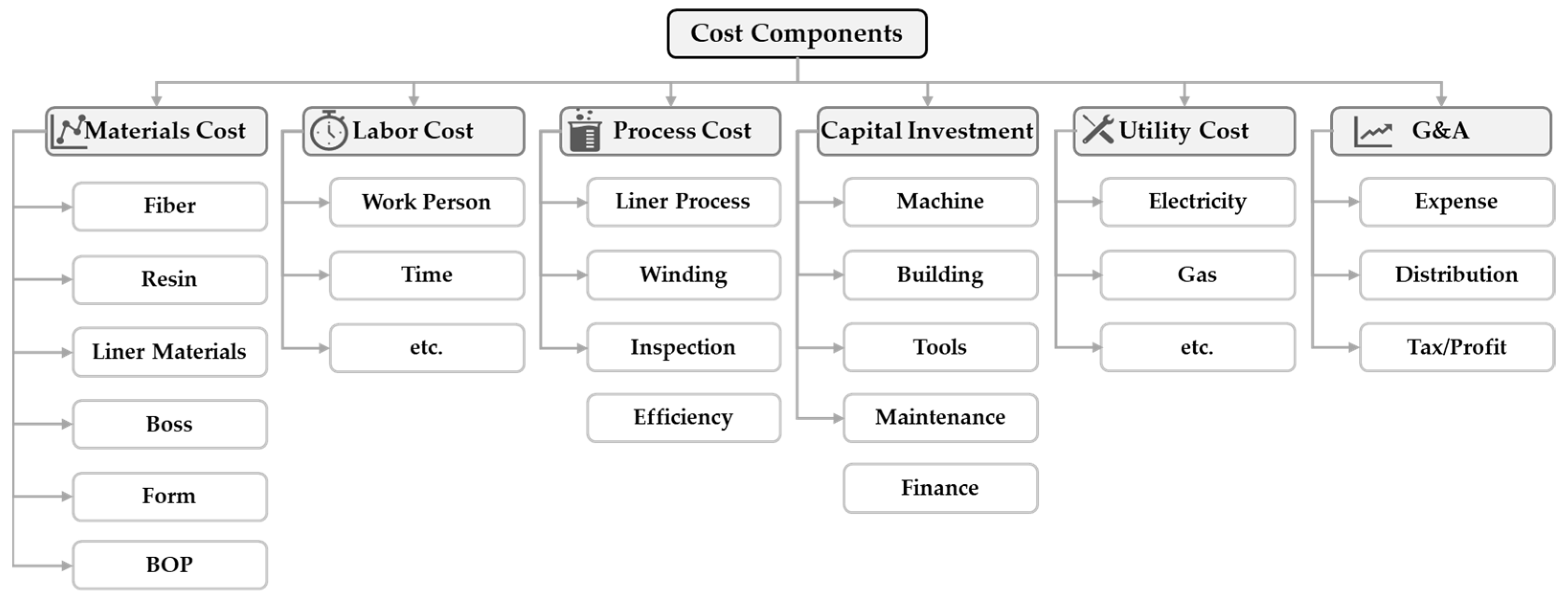
3.2. Cost Modeling of Composites
4. Cost Analysis of Compressed Hydrogen Storage Tanks
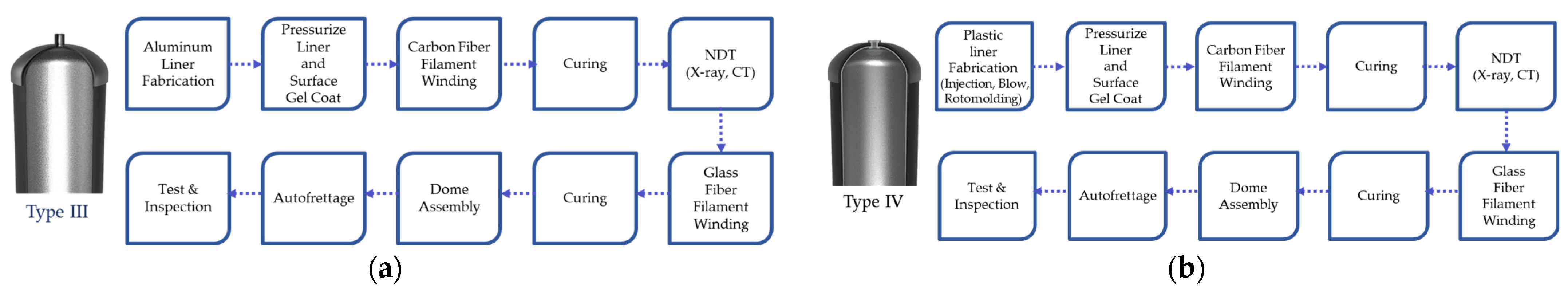
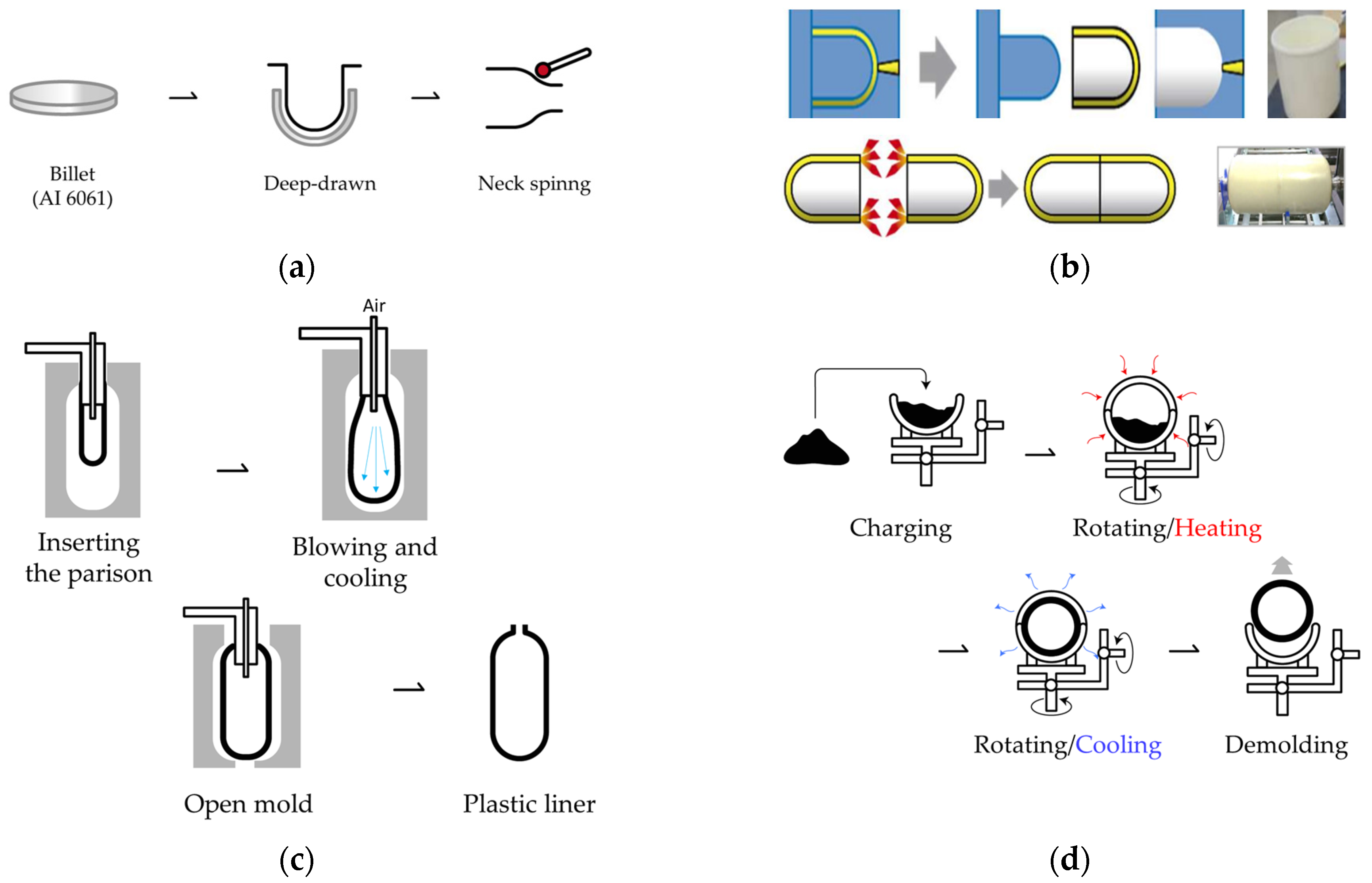
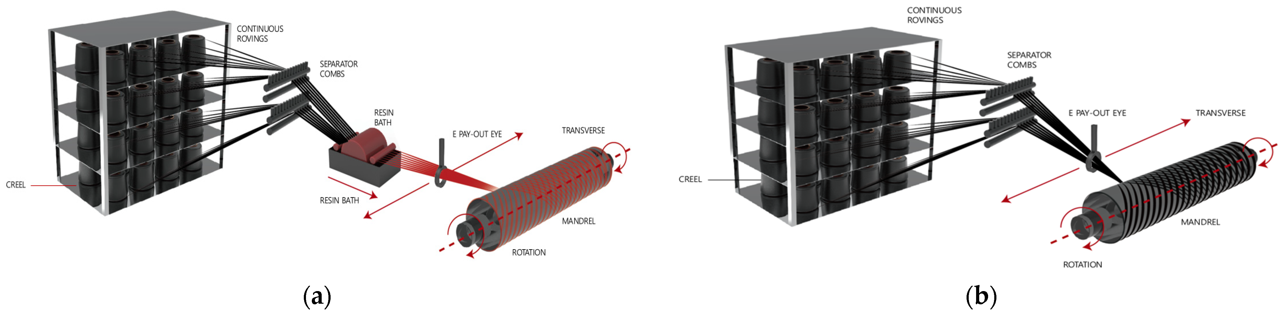
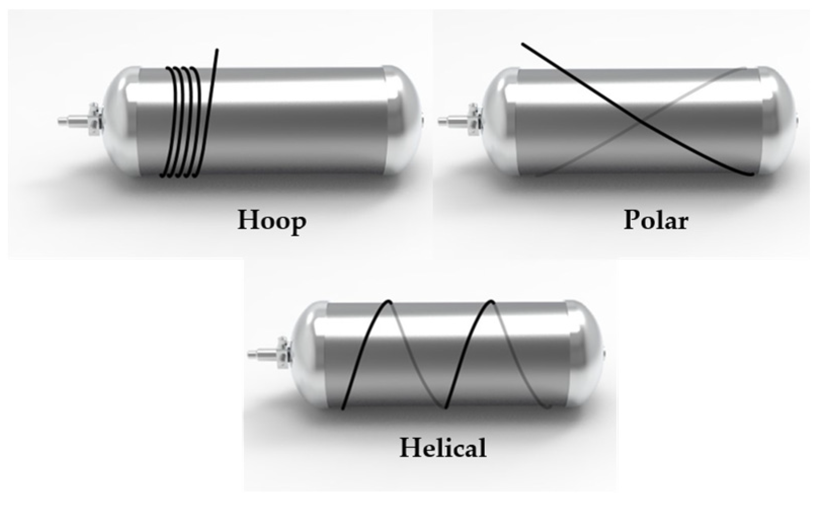
4.1. Manufacturing Process


| Company | Liner Material | Raw Material Cost [160] |
|---|---|---|
| Hexagon Purus [161,162] | HDPE | USD0.72/kg |
| Toyota [61] | PA6 | USD3.13/kg |
| Quantum [163] | Cross-lined polyethene PET | USD0.72/kg |
| French Atomic Commission (CEA) [147,164] | Thermoplastic (PA)and thermoset | USD3.13/kg |
| Ullit (France) [147] | PA6 | USD3.13/kg |
| Kautex [165] | PA6 | USD3.13/kg |
| DSM [161,166] | PA6 | USD3.13/kg |
| Hyundai [167] | PA6 | USD3.13/kg |
4.2. Cost Analysis
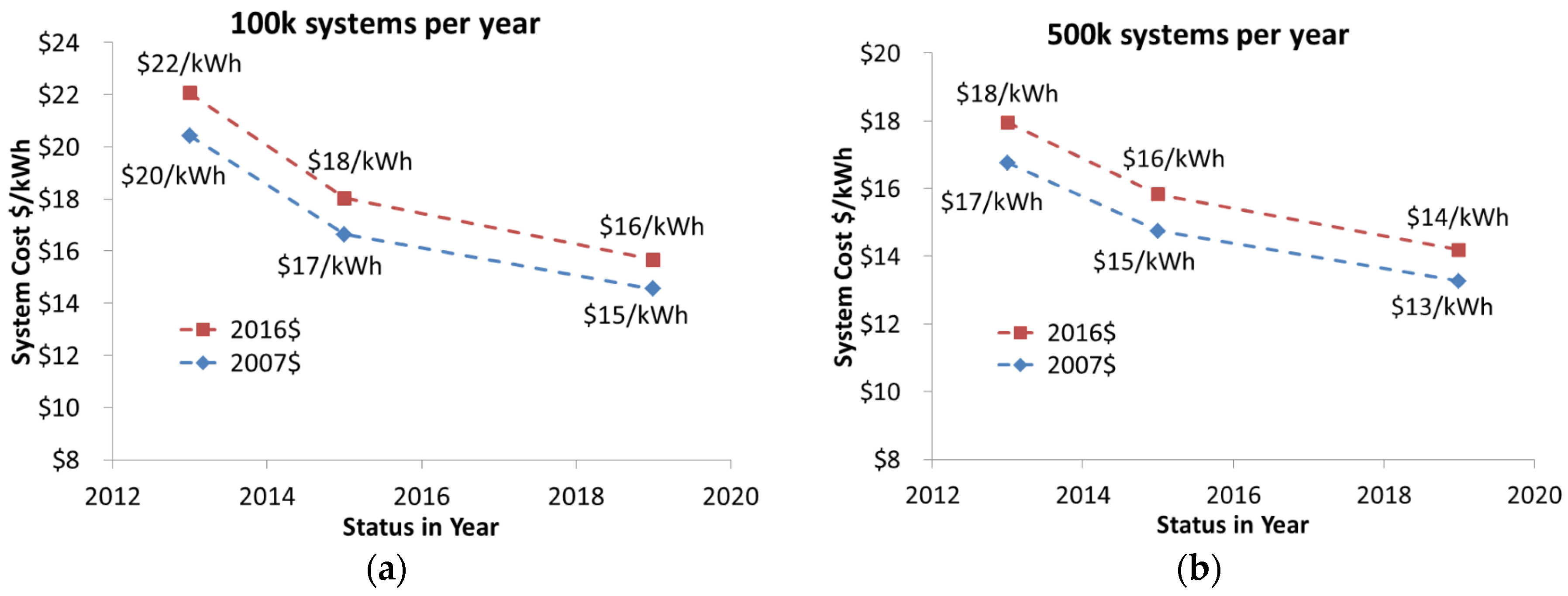
4.2.1. Cost Analysis and Forecasting of the DOE’s Hydrogen and Fuel Cells Program
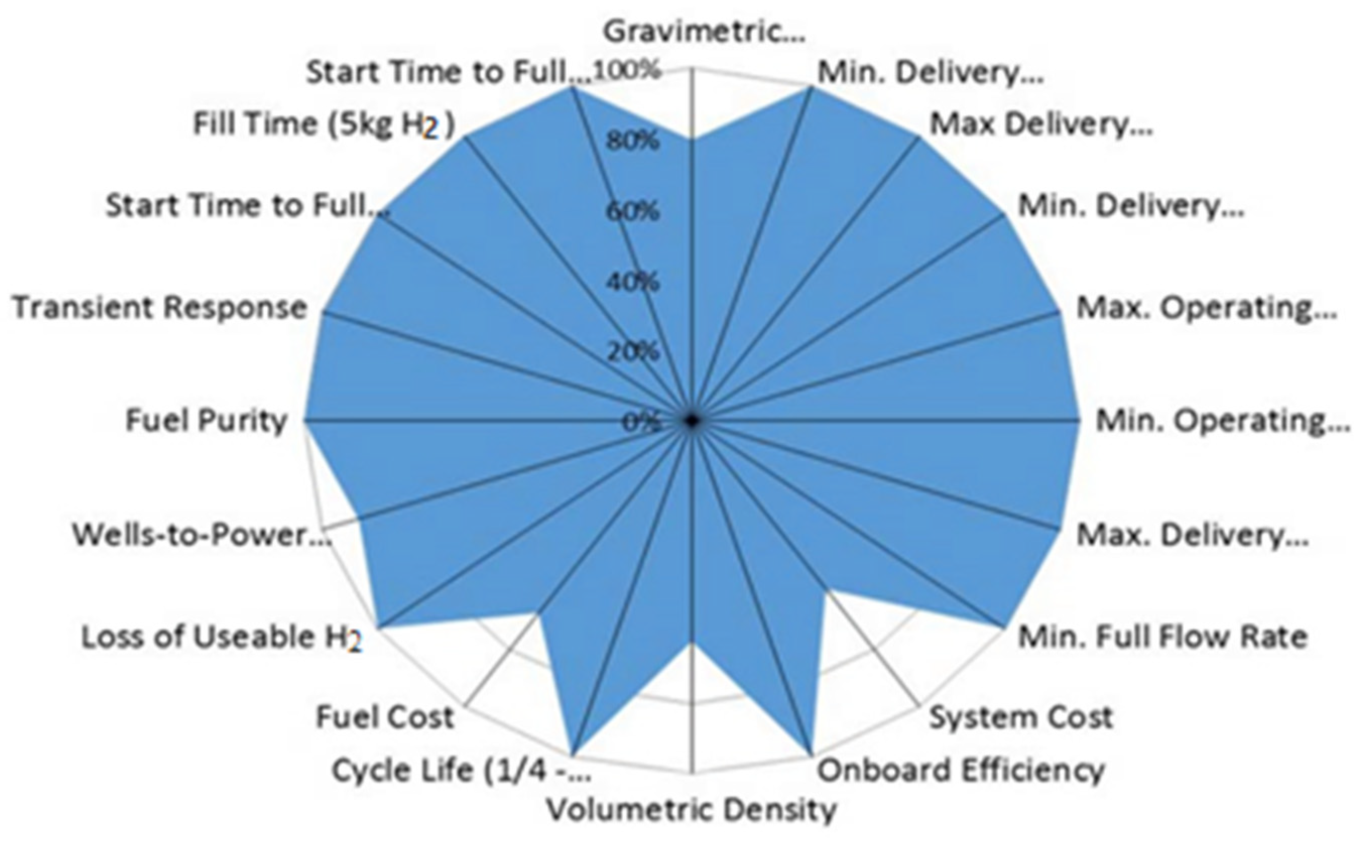
4.2.2. Cost Target, Analysis, and Estimation
4.2.3. Reduce Raw Materials
| Dry (Towpreg) Winding | Wet Winding | |
|---|---|---|
| Impregnation with resin |
|
|
| Advantage [176] |
|
|
| Disadvantage [176] |
|
|
| Winding speed [246] | 1 m/s, 0.02 kg/s | 20 m/s |
| Composite costs [240] | USD18 per kg composites | USD37 per kg composites |
4.2.4. Structural Design Optimization and Alternative Process Approach
| Authors | Year | Purpose (Model, Optimization Parameter, Software) | Results |
|---|---|---|---|
| Xu, P. [251] | 2010 | The weight minimum optimization (3D eight-node solid element SOLID95, ANSIS) | The optimal configurations are h: 1.38 mm, r: 30 mm, w: 7.73 kg, and P: 164.52 MPa |
| Yumiya, H. et al. [69,252] | 2015 |
| Reduced the amount of CFRP by 20 wt% |
| He, C. et al. [250] | 2016 | Metal lining reinforcement with shear field theory (1/4 finite element mode) (ANSYS) | Lightweight optimization design largely at a round section hydrogen storage tank |
| Alcantar, V. et al. [253] | 2017 | Weight minimization of Type IV 1400 mm(L), 465 mm(D), 5.6 kg H2 (SOLID191, ANSYS) | Reducing the weight by up to 9.8% and 11.2% compared to previously published vessel optimization research |
| Sharma, P. et al. [254] | 2020 | Netting analysis (1) Clairault equation (2) Maximum principal stress (3) Manufactured prototype (4) (ANSYS) | Models 1, 2, and 3 have reduced the composite from 35 kg to 30.5 kg, 23 kg, and 28 kg, respectively (Type III, 350 bar) |
| Hu, Z. et al. [255] | 2021 | Dome reinforcement (DR) technology to reduce carbon fiber (ABAQUS) | The dome reinforcement (DR) technology can help to reduce the consumption of carbon fiber by up to 5.5% in composite material |
| Cevotec [256] | 2021 | Automated dome reinforcements with fiber patch placement yield 15% improvements in weight and cost (ABAQUS) | Weight: −16% Cost: −11% Process time: −16% |
| Sharma, P. et al. [257] | 2022 | Dome shape on burst pressure, failure characteristics, and weight performance of the vessel (Type III) (ABAQUS, ANSYS) | Hydrogen storage kg per 1 kg vessel (hemispherical 0.03116, paraboloid 0.03094, ellipsoid (I) 0.03142, ellipsoid (II) 0.03143, ellipsoid (III) 0.03116, and isotensoid 0.03138) |
5. Conclusions
Author Contributions
Funding
Data Availability Statement
Acknowledgments
Conflicts of Interest
References
- Stocker, T. Climate Change 2013: The Physical Science Basis: Working Group I Contribution to the Fifth Assessment Report of the Intergovernmental Panel on Climate Change; Cambridge University Press: Cambridge, UK, 2014. [Google Scholar]
- Paris Agreement. Available online: https://unfccc.int/sites/default/files/english_paris_agreement.pdf (accessed on 2 April 2023).
- Carbon Neutrality Basic Law in Korea [Law No. 18469, 2021.9.24]. 2023. Available online: https://elaw.klri.re.kr/eng_mobile/viewer.do?hseq=59958&type=part&key=39 (accessed on 23 May 2023).
- Staffell, I.; Scamman, D.; Abad, A.V.; Balcombe, P.; Dodds, P.E.; Ekins, P.; Shah, N.; Ward, K.R. The role of hydrogen and fuel cells in the global energy system. Energy Environ. Sci. 2019, 12, 463–491. [Google Scholar] [CrossRef]
- Greene, D.L.; Ogden, J.M.; Lin, Z. Challenges in the designing, planning and deployment of hydrogen refueling infrastructure for fuel cell electric vehicles. ETransportation 2020, 6, 100086. [Google Scholar] [CrossRef]
- Tollefson, J. Hydrogen vehicles: Fuel of the future? Nature 2010, 464, 1262–1264. [Google Scholar] [CrossRef] [PubMed]
- Chalk, S.G.; Miller, J.F. Key challenges and recent progress in batteries, fuel cells, and hydrogen storage for clean energy systems. J. Power Sources 2006, 159, 73–80. [Google Scholar] [CrossRef]
- Abe, J.O.; Popoola, A.P.I.; Ajenifuja, E.; Popoola, O.M. Hydrogen energy, economy and storage: Review and recommendation. Int. J. Hydrogen Energy 2019, 44, 15072–15086. [Google Scholar] [CrossRef]
- Edwards, P.P.; Kuznetsov, V.L.; David, W.I.F. Hydrogen energy. Philos. Trans. R. Soc. A Math. Phys. Eng. Sci. 2007, 365, 1043–1056. [Google Scholar] [CrossRef] [PubMed]
- Mazloomi, K.; Gomes, C. Hydrogen as an energy carrier: Prospects and challenges. Renew. Sustain. Energy Rev. 2012, 16, 3024–3033. [Google Scholar] [CrossRef]
- Tashie-Lewis, B.C.; Nnabuife, S.G. Hydrogen Production, Distribution, Storage and Power Conversion in a Hydrogen Economy—A Technology Review. Chem. Eng. J. Adv. 2021, 8, 100172. [Google Scholar] [CrossRef]
- Wieliczko, M.; Stetson, N. Hydrogen technologies for energy storage: A perspective. MRS Energy Sustain. 2020, 7, E41. [Google Scholar] [CrossRef]
- 2022 Mirai Full Specs. Available online: https://toyota-cms-media.s3.amazonaws.com/wp-content/uploads/2021/11/2022-Toyota-Mirai_Product-Info-Guide.pdf (accessed on 1 April 2023).
- 2021 Clarity Fuel Cell Specifications & Features. Available online: https://hondanews.com/en-US/honda-automobiles/releases/release-4f88c507e72a4e7630685979cb04f2cb-2021-clarity-fuel-cell-specifications-features (accessed on 1 April 2023).
- NEXO Specifications. Available online: https://www.hyundai.com/kr/en/eco/nexo/highlights (accessed on 1 April 2023).
- Compare Fuel Cell Vehicles. Available online: https://www.fueleconomy.gov/feg/fcv_sbs.shtml (accessed on 25 April 2023).
- Rath, R.; Kumar, P.; Mohanty, S.; Nayak, S.K. Recent advances, unsolved deficiencies, and future perspectives of hydrogen fuel cells in transportation and portable sectors. Int. J. Energy Res. 2019, 43, 8931–8955. [Google Scholar] [CrossRef]
- Global Hydrogen Review. 2022. Available online: https://iea.blob.core.windows.net/assets/c5bc75b1-9e4d-460d-9056-6e8e626a11c4/GlobalHydrogenReview2022.pdf (accessed on 20 April 2023).
- O’Malley, K.; Ordaz, G.; Adams, J.; Randolph, K.; Ahn, C.C.; Stetson, N.T. Applied hydrogen storage research and development: A perspective from the US Department of Energy. J. Alloys Compd. 2015, 645, S419–S422. [Google Scholar] [CrossRef]
- Cano, Z.P.; Banham, D.; Ye, S.; Hintennach, A.; Lu, J.; Fowler, M.; Chen, Z. Batteries and fuel cells for emerging electric vehicle markets. Nat. Energy 2018, 3, 279–289. [Google Scholar] [CrossRef]
- Camacho, M.d.l.N.; Jurburg, D.; Tanco, M. Hydrogen fuel cell heavy-duty trucks: Review of main research topics. Int. J. Hydrogen Energy 2022, 47, 29505–29525. [Google Scholar] [CrossRef]
- Eberle, U.; Felderhoff, M.; Schüth, F. Chemical and Physical Solutions for Hydrogen Storage. Angew. Chem. Int. Ed. 2009, 48, 6608–6630. [Google Scholar] [CrossRef]
- Schlapbach, L.; Zuttel, A. Hydrogen-storage materials for mobile applications. Nature 2001, 414, 353–358. [Google Scholar] [CrossRef]
- Ahluwalia, R.; Hua, T.; Peng, J.-K.; Lasher, S.; McKenney, K.; Sinha, J.; Gardiner, M. Technical assessment of cryo-compressed hydrogen storage tank systems for automotive applications. Int. J. Hydrogen Energy 2010, 35, 4171–4184. [Google Scholar] [CrossRef]
- Ayakdas, O.; Aydin, L. Researches on Science and Art in 21st Century Turkey; Gece Kitapligi: Ankara, Türkiye, 2018; pp. 2890–2980. [Google Scholar]
- Lai, Q.W.; Paskevicius, M.; Sheppard, D.A.; Buckley, C.E.; Thornton, A.W.; Hill, M.R.; Gu, Q.F.; Mao, J.F.; Huang, Z.G.; Liu, H.K.; et al. Hydrogen Storage Materials for Mobile and Stationary Applications: Current State of the Art. Chemsuschem 2015, 8, 2789–2825. [Google Scholar] [CrossRef] [PubMed]
- Züttel, A. Materials for hydrogen storage. Mater. Today 2003, 6, 24–33. [Google Scholar] [CrossRef]
- Hydrogen Storage. Available online: https://www.energy.gov/eere/fuelcells/hydrogen-storage (accessed on 25 May 2023).
- Azkarate, I.T.; Barthélémy, H.A.L.; Hooker, P.H.; Jordan, T.K.; Keller, J.; Markert, F.D.; Steen, M.; Tchouvelev, A.A. Research Priority Workshop on Hydrogen Safety; Publications Office of the European Union: Luxembourg, 2018. [Google Scholar] [CrossRef]
- Moradi, R.; Groth, K.M. Hydrogen storage and delivery: Review of the state of the art technologies and risk and reliability analysis. Int. J. Hydrogen Energy 2019, 44, 12254–12269. [Google Scholar] [CrossRef]
- Adolfo Iulianelli, A.B. Advances in Hydrogen Production, Storage and Distribution; Elsevier: Cambridge, UK, 2014. [Google Scholar]
- Whiston, M.M.; Lima Azevedo, I.M.; Litster, S.; Samaras, C.; Whitefoot, K.S.; Whitacre, J.F. Hydrogen Storage for Fuel Cell Electric Vehicles: Expert Elicitation and a Levelized Cost of Driving Model. Environ. Sci. Technol. 2021, 55, 553–562. [Google Scholar] [CrossRef]
- Cerri, I.; Lefebvre-Joud, F.; Holtappels, P.; Honegger, K.; Stubos, T.; Millet, P.; Coordination, J.; Pfrang, A.; Bielewski, M.; Tzimas, E. Strategic Energy Technology Plan; European Commission: Brussels, Belgium, 2012. [Google Scholar]
- Kast, J.; Vijayagopal, R.; Gangloff, J.J.; Marcinkoski, J. Clean commercial transportation: Medium and heavy duty fuel cell electric trucks. Int. J. Hydrogen Energy 2017, 42, 4508–4517. [Google Scholar] [CrossRef]
- Cunanan, C.; Tran, M.-K.; Lee, Y.; Kwok, S.; Leung, V.; Fowler, M. A Review of Heavy-Duty Vehicle Powertrain Technologies: Diesel Engine Vehicles, Battery Electric Vehicles, and Hydrogen Fuel Cell Electric Vehicles. Clean Technol. 2021, 3, 474–489. [Google Scholar] [CrossRef]
- Gangloff, J.J.; Kast, J.; Morrison, G.; Marcinkoski, J. Design Space Assessment of Hydrogen Storage Onboard Medium and Heavy Duty Fuel Cell Electric Trucks. J. Electrochem. Energy Convers. Storage 2017, 14, 8. [Google Scholar] [CrossRef]
- Kast, J.; Morrison, G.; Gangloff, J.J.; Vijayagopal, R.; Marcinkoski, J. Designing hydrogen fuel cell electric trucks in a diverse medium and heavy duty market. Res. Transp. Econ. 2018, 70, 139–147. [Google Scholar] [CrossRef]
- Law, K.; Rosenfeld, J.; Han, V.; Chan, M.; Chiang, H.; Leonard, J. US Department of Energy Hydrogen Storage Cost Analysis; TIAX LLC: Lexington, MA, USA, 2013. [Google Scholar]
- Types of Vehicles by Weight Class. Available online: https://afdc.energy.gov/data (accessed on 30 April 2023).
- David, E. An overview of advanced materials for hydrogen storage. J. Mater. Process. Technol. 2005, 162, 169–177. [Google Scholar] [CrossRef]
- Barral, K.; Barthélémy, H. Hydrogen high pressure tanks storages: Overview and new trends due to H2 Energy specifications and constraints. In Proceedings of the 16th World Hydrogen Energy Conference (WHEC-16), Lyon, France, 13–16 June 2006. [Google Scholar]
- Jones, B.H.; Li, M.-C. Liner-less tanks for space application-design and manufacturing considerations. In Proceedings of the 5th Conference on Aerospace Materials, Processes, and Environmental Technology, Huntsville, AL, USA, 1 November 2003. [Google Scholar]
- Air, A.; Shamsuddoha, M.; Gangadhara Prusty, B. A review of Type V composite pressure vessels and automated fibre placement based manufacturing. Compos. Part B Eng. 2023, 253, 110573. [Google Scholar] [CrossRef]
- Gardiner, G. Infinite Composites: Type V Tanks for Space, Hydrogen, Automotive and More. Composites World, 27 June 2023. [Google Scholar]
- Demonstrating the Future of Composite Space Tank Technology. Available online: https://www.nccuk.com/media/0i5b10jw/space-tank.pdf (accessed on 27 June 2023).
- Gardiner, G. Viritech and Haydale Pursue New Functionalized Materials for Type V Composite Vessels for Hydrogen Storage. Composites World. 28 April 2023. Available online: https://www.compositesworld.com/news/viritech-and-haydale-pursue-new-functionalized-materials-for-type-v-composite-vessels-for-hydrogen-storage (accessed on 6 May 2023).
- Legault, M. The First Commercial Type V Composite Pressure Vessel; Composites world: Cincinnati, OH, USA, 2012. [Google Scholar]
- Ebermann, M.; Bogenfeld, R.; Kreikemeier, J.; Glüge, R. Analytical and numerical approach to determine effective diffusion coefficients for composite pressure vessels. Compos. Struct. 2022, 291, 115616. [Google Scholar] [CrossRef]
- Rivard, E.; Trudeau, M.; Zaghib, K. Hydrogen storage for mobility: A review. Materials 2019, 12, 1973. [Google Scholar] [CrossRef]
- Hassan, I.; Ramadan, H.S.; Saleh, M.A.; Hissel, D. Hydrogen storage technologies for stationary and mobile applications: Review, analysis and perspectives. Renew. Sustain. Energy Rev. 2021, 149, 111311. [Google Scholar] [CrossRef]
- Azeem, M.; Ya, H.H.; Alam, M.A.; Kumar, M.; Stabla, P.; Smolnicki, M.; Gemi, L.; Khan, R.; Ahmed, T.; Ma, Q.; et al. Application of filament winding technology in composite pressure vessels and challenges: A review. J. Energy Storage 2022, 49, 103468. [Google Scholar] [CrossRef]
- Barthélémy, H.; Weber, M.; Barbier, F. Hydrogen storage: Recent improvements and industrial perspectives. Int. J. Hydrogen Energy 2017, 42, 7254–7262. [Google Scholar] [CrossRef]
- Amirthan, T.; Perera, M.S.A. The role of storage systems in hydrogen economy: A review. J. Nat. Gas Sci. Eng. 2022, 108, 104843. [Google Scholar] [CrossRef]
- Gardiner, G. Hydrogen Is Poised to Fuel Composites Growth, Part 1. Composites World, 24 September 2021. [Google Scholar]
- Meyer, K.; Pignagnoli, F.; Potts, D.; Hunter, G. Lightweighting matters in energy storage. Reinf. Plast. 2014, 58, 20–23. [Google Scholar] [CrossRef]
- Aminudin, M.; Kamarudin, S.; Lim, B.; Majilan, E.; Masdar, M.; Shaari, N. An overview: Current progress on hydrogen fuel cell vehicles. Int. J. Hydrogen Energy 2022, 48, 4371–4388. [Google Scholar] [CrossRef]
- Hong, B.K.; Kim, S.H. Recent advances in fuel cell electric vehicle technologies of Hyundai. ECS Trans. 2018, 86, 3. [Google Scholar] [CrossRef]
- Sery, J.; Leduc, P. Fuel cell behavior and energy balance on board a Hyundai Nexo. Int. J. Engine Res. 2022, 23, 709–720. [Google Scholar] [CrossRef]
- Hong, B.K.; Kim, S.H.; Kim, C.M. Powering the Future through Hydrogen and Polymer Electrolyte Membrane Fuel Cells: Current commercialisation and key challenges with focus on work at Hyundai. Johns. Matthey Technol. Rev. 2020, 64, 236–251. [Google Scholar] [CrossRef]
- Yamashita, A.; Kondo, M.; Goto, S.; Ogami, N. Development of High-Pressure Hydrogen Storage System for the Toyota “Mirai”; SAE Technical Paper 2015-01-1169; SAE International: Warrendale, PA, USA, 2015. [Google Scholar] [CrossRef]
- Ube Industries Supplying Nylon 6 Resin for High-Pressure Hydrogen Tanks in Latest Toyota MIRAI Fuel Cell Vehicle. Available online: https://www.ube.co.jp/ube/en/news/2020/20210303_01.html (accessed on 1 April 2023).
- De Almeida, S.C.A.; Kruczan, R. Effects of drivetrain hybridization on fuel economy, performance and costs of a fuel cell hybrid electric vehicle. Int. J. Hydrogen Energy 2021, 46, 39404–39414. [Google Scholar] [CrossRef]
- Tanaka, S.; Nagumo, K.; Yamamoto, M.; Chiba, H.; Yoshida, K.; Okano, R. Fuel cell system for Honda CLARITY fuel cell. ETransportation 2020, 3, 100046. [Google Scholar] [CrossRef]
- Brachmann, T. Honda Clarity Fuel Cell. Available online: https://www.hfc-hungary.org/hylaw/HyLaw_presentation_HONDA_2018_sept.pdf (accessed on 1 April 2023).
- Kimura, K.; Kawasaki, T.; Ohmura, T.; Atsumi, Y.; Shimizu, K. Development of new fuel cell vehicle Clarity Fuel Cell. Honda RD Tech. Rev. 2016, 28, 1–7. [Google Scholar]
- GLC F-CELL Goes Into Preproduction: World’s First Electric Vehicle with Fuel-Cell/Battery Powertrai. Available online: https://mercedes-benz-media.co.uk/en-gb/releases/41 (accessed on 3 April 2023).
- Charolais, A.; Ammouri, F.; Vyazmina, E.; Werlen, E.; Harris, A. Safety Watchdog for universally safe gaseous high pressure hydrogen fillings. Int. J. Hydrogen Energy 2021, 46, 16019–16029. [Google Scholar] [CrossRef]
- BMW Group Reaffirms Commitment to Hydrogen Fuel Cell Technology. Available online: https://www.bmwblog.com/2020/03/30/bmw-group-reaffirms-commitment-to-hydrogen-fuel-cell-technology/ (accessed on 28 April 2023).
- Yumiya, H.; Kizaki, M.; Asai, H. Toyota fuel cell system (TFCS). World Electr. Veh. J. 2015, 7, 85–92. [Google Scholar] [CrossRef]
- Teng, T.; Zhang, X.; Dong, H.; Xue, Q. A comprehensive review of energy management optimization strategies for fuel cell passenger vehicle. Int. J. Hydrogen Energy 2020, 45, 20293–20303. [Google Scholar] [CrossRef]
- DOE National Clean Hydrogen Strategy and Roadmap (Draft). Available online: https://www.hydrogen.energy.gov/clean-hydrogen-strategy-roadmap.html (accessed on 7 April 2023).
- The Worldwide Overview of Heavy-Duty Trucks Running on Hydrogen. Available online: https://fuelcelltrucks.eu/ (accessed on 20 April 2023).
- Sharpe, B.; Basma, H. A Meta-Study of Purchase Costs for Zero-Emission Trucks; International Council on Clean Energy Transportation: Washington, DC, USA, 2022. [Google Scholar]
- Basma, H.; Rodríguez, F. Fuel cell electric tractor-trailers: Technology overview and fuel economy. Int. Counc. Clean Transp. Work. Pap. 2022, 23, 2022. [Google Scholar]
- Danebergs, J. Techno-Economic Study of Hydrogen as a Heavy-Duty Truck Fuel. A Case Study on the Transport Corridor Oslo–Trondheim. Master’s Thesis, Universitat Politècnica de Catalunya, Barcelona, Spain, 2020. [Google Scholar]
- XCIENT Fuel Cell. Available online: https://trucknbus.hyundai.com/hydrogen/ko/download/catalog-xcient-fuel-cell-en.pdf (accessed on 1 May 2023).
- Hyundai Motor’s XCIENT Fuel Cell Heavy-Duty Trucks to Hit German Roads. Available online: https://www.hyundaimotorgroup.com/news/CONT0000000000046014 (accessed on 30 April 2023).
- Hyundai Motor’s Delivery of XCIENT Fuel Cell Trucks in Europe Heralds Its Commercial Truck Expansion to Global Markets. Available online: https://hyundai-hm.com/en/2020/10/07/hyundai-motors-delivery-of-xcient-fuel-cell-trucks-in-europe-heralds-its-commercial-truck-expansion-to-global-markets/ (accessed on 2 May 2023).
- Hyzon Hymax Series Built for Your Operations, without the Emissions. Available online: https://www.hyzonmotors.com/vehicles/hyzon-hymax-series (accessed on 25 April 2023).
- Nehls, G. Daimler Truck Tests Fuel-Cell Truck with Liquid Hydrogen. Available online: https://www.compositesworld.com/news/daimler-truck-tests-fuel-cell-truck-with-liquid-hydrogen (accessed on 20 April 2023).
- Swiss Fuel Cell Truck. 2016. Available online: https://esoro.ch/en/portfolio-item/swiss-fuel-cell-truck-2016/ (accessed on 21 April 2023).
- Products and Services. Available online: https://www.scania.com/group/en/home.html (accessed on 20 April 2023).
- Hydrogen Tank. Available online: https://hyfindr.com/hydrogen-tank/ (accessed on 10 April 2023).
- Advanced Structural Technologies, Inc. H2 MAX Brochures. Available online: https://astforgetech.com/wp-content/uploads/2022/04/H2Max-Brochure.pdf (accessed on 25 April 2023).
- Liaoning Alsafe Technology. Hydrogen Storage Tank. Available online: http://www.alsafegascylinders.com/?products_5/26.html (accessed on 25 April 2023).
- AMS Composite Cylinders. Hydrogen Fuel Cells. Available online: https://ams-composites.com/hydrogen-fuel-cells/ (accessed on 25 April 2023).
- XPERION—XPERION Delivers X-STORE Type 4 Hydrogen Cylinders for Regional Trains Developed by Alstom. Available online: https://www.avanco.de/en/news/xperion-xperion-delivers-x-store-type-4-hydrogen-cylinders-for-regional-trains-developed-by-alstom/ (accessed on 21 April 2023).
- Cylinder Holdings. Hydrogen Products. Available online: https://www.cylinders.cz/en/vodik/vodikove-produkty/a-159/ (accessed on 26 April 2023).
- Highway to Hydrogen. Available online: https://www.catecgases.com/hydrogen (accessed on 26 April 2023).
- EKC. Type IV Cylinders. Available online: https://ekcuae.com/3d-flip-book/type-4-composite-cylinder/ (accessed on 25 April 2023).
- Faber Cylinders. Available online: https://drawings.faber-italy.com/eng-product-hydrogen.asp (accessed on 25 April 2023).
- Hexagon Purus. Datasheets. Available online: https://hexagonpurus.com/brochures (accessed on 22 April 2023).
- Hanwha Cimarron. Gas Transport and Storage. Available online: https://hanwhacimarron.com/ (accessed on 25 April 2023).
- Hanwha Solutions Advanced Materials Division. Hydrogen Tank. Available online: https://pict.space/hanwhasolutions/en/scene_12_en.html (accessed on 25 April 2023).
- Kim, D.-H. Hydrogen Fuel Tank Maker Iljin Hysolus Eyes August IPO. Available online: https://www.kedglobal.com/hydrogen-conomy/newsView/ked202107120006 (accessed on 2 May 2023).
- Infinite Composites. IC Products & Services. Available online: https://www.infinitecomposites.com/infinite-composite-pressure-vessels (accessed on 25 April 2023).
- Luxfer. Spec Tables. Available online: https://www.luxfercylinders.com/products/ (accessed on 24 April 2023).
- Mahytec. Compressed Hydrogen Storage. Available online: https://www.mahytec.com/en/compressed-hydrogen-storage/ (accessed on 25 April 2023).
- NPROXX. Type 4 Pressure Vessels. Available online: https://www.nproxx.com/capabilities/type-4-pressure-vessels/ (accessed on 23 April 2023).
- Plastic Omnium. A Reference Player in Hydrogen Mobility. Available online: https://www.plasticomnium.com/wp-content/uploads/2021/01/plastic-omnium-hydrogen-conference-september-2020-en.pdf (accessed on 24 April 2023).
- Quantum Fuel Systems. Hydrogen Cylinder General Specifications. Available online: https://www.qtww.com/wp-content/uploads/2019/01/H2-Tank-Specifications-Sept-2021-All-Tanks.pdf (accessed on 20 April 2023).
- Steelhead Composites. Available online: https://steelheadcomposites.com/hydrogen-storage/ (accessed on 24 April 2023).
- H2 Mobility Faurecia Hydrogen Strategy. Available online: https://www.faurecia.com/sites/groupe/files/investisseurs/2019%2006%2014%20-%20Kepler%20Cheuvreux%20Event%20-%20Hydrogen%20-%20pour%20envoi.pdf (accessed on 1 April 2023).
- Toyoda Gosei Launches Large High Pressure Hydrogen Tank for Commercial Vehicles. Available online: https://www.toyoda-gosei.com/news/details.php?id=338 (accessed on 26 April 2023).
- Carbon4Tank 700 Bar Hydrogen Vessels for Heavy Duty Trucks. Available online: https://voith.com/corp-en/drives-transmissions/drive-h2.html (accessed on 24 April 2023).
- Wiretough. Hydrogen Storage Solutions. Available online: https://wiretough.com/wp-content/uploads/2023/03/Hydrogen-Storage-2023.pdf (accessed on 28 April 2023).
- Li, J.; Lv, R.; Gu, C.; Liu, Y.; Li, J.; Li, X. An Ageing Test Standards Analysis on Thermoplastic Liners of Type IV Composite Hydrogen Storage Tanks. Energies 2023, 16, 2818. [Google Scholar] [CrossRef]
- Jiangsu Guofu Hydrogen Energy Equipment Co., Ltd. Vehicle Hydrogen Supply System. Available online: https://www.en.guofuhee.com/Product/detil/id/11.html (accessed on 23 April 2023).
- On-Board Fuel Cell Hydrogen Supply System. Available online: http://suzhou.sinomatech.com/yw/products_and_services/CompressedHydrogenProductsandHydrogenSupplySystem/1222.html (accessed on 28 April 2023).
- Zhao, F.; Mu, Z.; Hao, H.; Liu, Z.; He, X.; Victor Przesmitzki, S.; Ahmad Amer, A. Hydrogen Fuel Cell Vehicle Development in China: An Industry Chain Perspective. Energy Technol. 2020, 8, 2000179. [Google Scholar] [CrossRef]
- Hyundai Motor Sells Hydrogen-Powered Truck Xcient in South Korea. Available online: https://www.kedglobal.com/automobiles/newsView/ked202212080013 (accessed on 2 May 2023).
- Forvia. PressKit IAA Transportation. 2022. Available online: https://www.faurecia.com/sites/groupe/files/documents/IAA%20TRANSPORTATION%20PRESS%20KIT.pdf (accessed on 2 May 2023).
- Plug & Drive H2 Storage System. Available online: https://voith.com/corp-en/products-services/composites-solutions/carbon4tank.html (accessed on 1 March 2023).
- Park, C.; Lim, S.; Shin, J.; Lee, C.-Y. How much hydrogen should be supplied in the transportation market? Focusing on hydrogen fuel cell vehicle demand in South Korea: Hydrogen demand and fuel cell vehicles in South Korea. Technol. Forecast. Soc. Chang. 2022, 181, 121750. [Google Scholar] [CrossRef]
- XCIENT Fuel Cell Tractor. Available online: https://trucknbus.hyundai.com/hydrogen/ko/download/catalog-Xcient-fuel-cell-tractor.pdf (accessed on 1 May 2023).
- Curran, R.; Raghunathan, S.; Price, M. Review of aerospace engineering cost modelling: The genetic causal approach. Prog. Aerosp. Sci. 2004, 40, 487–534. [Google Scholar] [CrossRef]
- Newnan, D.G.; Eschenbach, T.G.; Lavelle, J.P. Engineering Economic Analysis; Oxford University Press: Oxford, UK, 2004; Volume 2. [Google Scholar]
- Stewart, R.D.; Wyskida, R.M.; Johannes, J.D. Cost Estimator’s Reference Manual; John Wiley & Sons: Hoboken, NJ, USA, 1995; Volume 15, p. 41. [Google Scholar]
- Fabrycky, W.J.; Blanchard, B.S. Life-Cycle Cost and Economic Analysis; Prentice Hall: Englewood Cliffs, NJ, USA, 1991; Volume 135383234. [Google Scholar]
- Asiedu, Y.; Gu, P. Product life cycle cost analysis: State of the art review. Int. J. Prod. Res. 1998, 36, 883–908. [Google Scholar] [CrossRef]
- Esawi, A.; Ashby, M. Cost estimates to guide pre-selection of processes. Mater. Des. 2003, 24, 605–616. [Google Scholar] [CrossRef]
- Niazi, A.; Dai, J.S.; Balabani, S.; Seneviratne, L. Product cost estimation: Technique classification and methodology review. J. Manuf. Sci. Eng.-Trans. ASME 2006, 128, 563–575. [Google Scholar] [CrossRef]
- Yves, B.; Laura, V.; Carwyn, W. Developing a cost comparison technique for hand layup versus automated fibre placement, and infusion versus out-of-autoclave. In Proceedings of the SAMPE Europe Conference 2017, Stuttgart, Germany, 14–16 November 2017. [Google Scholar]
- Bloch, C.; Ranganthan, R. Process based cost modeling. In Proceedings of the 1991 Eleventh IEEE/CHMT International Electronics Manufacturing Technology Symposium, San Francisco, CA, USA, 16–18 September 1991; pp. 406–412. [Google Scholar]
- Nadeau, M.-C.; Kar, A.; Roth, R.; Kirchain, R. A dynamic process-based cost modeling approach to understand learning effects in manufacturing. Int. J. Prod. Econ. 2010, 128, 223–234. [Google Scholar] [CrossRef]
- Field, F.; Kirchain, R.; Roth, R. Process cost modeling: Strategic engineering and economic evaluation of materials technologies. JOM 2007, 59, 21–32. [Google Scholar] [CrossRef]
- LeBlanc, D.J.; Lorenzana, J.; Kokawa, A.; Bettner, T.; Timson, F. Advanced Composite Cost Estimating Manual. Volume II. Appendix; Northrop Corporation: Hawthorne, CA, USA, 1976. [Google Scholar]
- Zaloom, V.; Miller, C. A review of cost estimating for advanced composite materials applications. Eng. Costs Prod. Econ. 1982, 7, 81–86. [Google Scholar] [CrossRef]
- Åkermo, M.; Åström, B.T. Modelling component cost in compression moulding of thermoplastic composite and sandwich components. Compos. Part A Appl. Sci. Manuf. 2000, 31, 319–333. [Google Scholar] [CrossRef]
- Bader, M.G. Selection of composite materials and manufacturing routes for cost-effective performance. Compos. Part A Appl. Sci. Manuf. 2002, 33, 913–934. [Google Scholar] [CrossRef]
- Verrey, J.; Wakeman, M.; Michaud, V.; Månson, J.-A. Manufacturing cost comparison of thermoplastic and thermoset RTM for an automotive floor pan. Compos. Part A Appl. Sci. Manuf. 2006, 37, 9–22. [Google Scholar] [CrossRef]
- Fuchs, E.R.; Field, F.R.; Roth, R.; Kirchain, R.E. Strategic materials selection in the automobile body: Economic opportunities for polymer composite design. Compos. Sci. Technol. 2008, 68, 1989–2002. [Google Scholar] [CrossRef]
- Ye, J.; Zhang, B.; Qi, H. Cost estimates to guide manufacturing of composite waved beam. Mater. Des. 2009, 30, 452–458. [Google Scholar] [CrossRef]
- Schubel, P.J. Cost modelling in polymer composite applications: Case study–Analysis of existing and automated manufacturing processes for a large wind turbine blade. Compos. Part B Eng. 2012, 43, 953–960. [Google Scholar] [CrossRef]
- Weiland, F.; Weimer, C.; Dumont, F.; Katsiropoulos, C.V.; Pantelakis, S.G.; Sitaras, I.; Skordos, A.; Berthé, E.; De Luca, P. Process and cost modelling applied to manufacture of complex aerospace composite part. Plast. Rubber Compos. 2013, 42, 427–436. [Google Scholar] [CrossRef]
- Hagnell, M.K.; Åkermo, M. A composite cost model for the aeronautical industry: Methodology and case study. Compos. Part B Eng. 2015, 79, 254–261. [Google Scholar] [CrossRef]
- Ellringmann, T.; Wilms, C.; Warnecke, M.; Seide, G.; Gries, T. Carbon fiber production costing: A modular approach. Text. Res. J. 2016, 86, 178–190. [Google Scholar] [CrossRef]
- Soares, B.A.; Henriques, E.; Ribeiro, I.; Freitas, M. Cost analysis of alternative automated technologies for composite parts production. Int. J. Prod. Res. 2019, 57, 1797–1810. [Google Scholar] [CrossRef]
- Hagnell, M.; Kumaraswamy, S.; Nyman, T.; Åkermo, M. From aviation to automotive-a study on material selection and its implication on cost and weight efficient structural composite and sandwich designs. Heliyon 2020, 6, e03716. [Google Scholar] [CrossRef]
- Schubel, P. Technical cost modelling for a generic 45-m wind turbine blade producedby vacuum infusion (VI). Renew. Energy 2010, 35, 183–189. [Google Scholar] [CrossRef]
- Hua, T.; Ahluwalia, R.; Peng, K.-K.; Kromer, M.; Lasher, S.; McKenney, K.; Law, K.; Sinha, J. Technical Assessment of Compressed Hydrogen Storage Tank Systems for Automotive Applications; Argonne National Laboratory: Lemont, IL, USA, 2010. [Google Scholar] [CrossRef]
- Sharma, R.; Pachauri, A. A review of pressure vessels regarding their design, manufacturing, testing, materials, and inspection. Mater. Today Proc. 2023, in press. [Google Scholar] [CrossRef]
- Chen, Y.; Zhao, S.; Ma, H.; Wang, H.; Hua, L.; Fu, S. Analysis of Hydrogen Embrittlement on Aluminum Alloys for Vehicle-Mounted Hydrogen Storage Tanks: A Review. Metals 2021, 11, 1303. [Google Scholar] [CrossRef]
- Shen, F.C. A filament-wound structure technology overview. Mater. Chem. Phys. 1995, 42, 96–100. [Google Scholar] [CrossRef]
- Barthélémy, H. Hydrogen storage—Industrial prospectives. Int. J. Hydrogen Energy 2012, 37, 17364–17372. [Google Scholar] [CrossRef]
- McWhorter, S.; Adams, T.; Rawls, G. IV. F. 5 Load-Sharing Polymeric Liner for Hydrogen Storage Composite Tanks; FY 2014 Annual Progress Report; United States Department of Energy: Washington, DC, USA, 2014. [Google Scholar]
- Villalonga, S.; Nony, F.; Magnier, C.; Yvernes, J.; Thomas, C.; Delmas, B.; Mazabraud, P. Composite 700 bar-vessel for on-board compressed gaseous hydrogen storage. In Proceedings of the 17th International Conference on Composite Materials, Edinburgh, UK, 27–31 July 2009. [Google Scholar]
- Wang, X.; Tian, M.; Chen, X.; Xie, P.; Yang, J.; Chen, J.; Yang, W. Advances on materials design and manufacture technology of plastic liner of type IV hydrogen storage vessel. Int. J. Hydrogen Energy 2022, 47, 8382–8408. [Google Scholar] [CrossRef]
- McWhorter, S. Load-Sharing Polymeric Liner for Hydrogen Storage Composite Tanks; Project ID # ST112; 18 June 2014. Available online: https://www.hydrogen.energy.gov/pdfs/review14/st112_mcwhorter_2014_p.pdf (accessed on 4 April 2023).
- The High Pressure Hydrogen Tank Produced at Inabe Plant. Available online: https://www.toyoda-gosei.com/upload/news_en/268/bc2f923823015e0b0f1a69c5db679179.pdf (accessed on 2 April 2023).
- Klopffer, M.-H.; Berne, P.; Espuche, É. Development of innovating materials for distributing mixtures of hydrogen and natural gas. Study of the barrier properties and durability of polymer pipes. Oil Gas Sci. Technol.–Rev. D’ifp Energ. Nouv. 2015, 70, 305–315. [Google Scholar] [CrossRef]
- Yersak, T.A.; Baker, D.R.; Yanagisawa, Y.; Slavik, S.; Immel, R.; Mack-Gardner, A.; Herrmann, M.; Cai, M. Predictive model for depressurization-induced blistering of type IV tank liners for hydrogen storage. Int. J. Hydrogen Energy 2017, 42, 28910–28917. [Google Scholar] [CrossRef]
- Sun, Y.; Lv, H.; Zhou, W.; Zhang, C. Research on hydrogen permeability of polyamide 6 as the liner material for type IV hydrogen storage tank. Int. J. Hydrogen Energy 2020, 45, 24980–24990. [Google Scholar] [CrossRef]
- Dallali, M.; Gigliotti, M.; Lainé, E.; Grandidier, J.-C.; Henry, N. Effects of surface preparation on bond behavior CFRP-to-PA6 bonded joints using different adhesives. Int. J. Hydrogen Energy 2021, 46, 33496–33510. [Google Scholar] [CrossRef]
- Li, J.; Zhao, C.; Jia, F.; Li, S.; Ma, S.; Liang, J. Optimization of injection molding process parameters for the lining of IV hydrogen storage cylinder. Sci. Rep. 2023, 13, 665. [Google Scholar] [CrossRef] [PubMed]
- Zaami, A.; Schäkel, M.; Baran, I.; Bor, T.C.; Janssen, H.; Akkerman, R. Temperature variation during continuous laser-assisted adjacent hoop winding of type-IV pressure vessels: An experimental analysis. J. Compos. Mater. 2020, 54, 1717–1739. [Google Scholar] [CrossRef]
- Barboza Neto, E.S.; Coelho, L.A.F.; Forte, M.M.d.C.; Amico, S.C.; Ferreira, C.A. Processing of a LLDPE/HDPE pressure vessel liner by rotomolding. Mater. Res. 2014, 17, 236–241. [Google Scholar] [CrossRef]
- Benitez, A.; Wulf, C.; de Palmenaer, A.; Lengersdorf, M.; Röding, T.; Grube, T.; Robinius, M.; Stolten, D.; Kuckshinrichs, W. Ecological assessment of fuel cell electric vehicles with special focus on type IV carbon fiber hydrogen tank. J. Clean. Prod. 2021, 278, 123277. [Google Scholar] [CrossRef]
- Murray, B.R.; Doyle, A.; Feerick, P.; Semprimoschnig, C.O.; Leen, S.B.; Brádaigh, C.M.Ó. Rotational moulding of PEEK polymer liners with carbon fibre/PEEK over tape-placement for space cryogenic fuel tanks. Mater. Des. 2017, 132, 567–581. [Google Scholar] [CrossRef]
- Raw Materials & Prices. Available online: https://plasticker.de/preise/preise_monat_single_en.php?submit=x&form=Granulat&werkstoff=PA%206&dauer=12 (accessed on 2 April 2023).
- The Company Has Delivered Lightweight Tanks Made From Filament-Wound Carbon Fiber and High-Density Polyethylene Liners. Available online: https://www.plasticstoday.com/automotive-and-mobility/hexagon-composites-enters-heavy-duty-fuel-cell-truck-market-hydrogen (accessed on 20 April 2023).
- Advanced CNG Fuel Storage Tanks. Available online: https://www.qtww.com/product/q-lite-lightest-cng-tanks/# (accessed on 5 April 2023).
- Su, Y.; Lv, H.; Zhou, W.; Zhang, C. Review of the Hydrogen Permeability of the Liner Material of Type IV On-Board Hydrogen Storage Tank. World Electr. Veh. J. 2021, 12, 130. [Google Scholar] [CrossRef]
- Villalonga, S.; Thomas, C.; Nony, C.; Thiebaud, F.; Geli, M.; Lucas, A.; Knobloch, K.; Maugy, C. Applications of full thermoplastic composite for type IV 70 MPa high pressure vessels. In Proceedings of the International Conference on Composite Materials, Jeju Island, Republic of Korea, 21–26 August 2011. [Google Scholar]
- Kautex Produces 320-Liter Hydrogen Liner in Blow Molding Process. Available online: https://www.kautex-group.com/en/kautex-produces-320-liter-hydrogen-liner-in-blow-molding-process.html (accessed on 10 April 2023).
- Manufacturing Lightweight and Cost-Effective Tanks for Hydrogen Vehicles. Available online: https://www.dsm.com/engineering-materials/en_US/industry/automotive/fuel-systems/hydrogen-tanks.html (accessed on 6 April 2023).
- Hydrogen Society. What Moves an FCEV. Available online: https://www.hyundaimotorgroup.com/story/CONT0000000000002997 (accessed on 20 April 2023).
- Mallick, K.; Cronin, J.; Ryan, K.; Arzberger, S.; Munshi, N.; Paul, C.; Welsh, J.S. An integrated systematic approach to linerless composite tank development. In Proceedings of the 46th AIAA/ASME/ASCE/AHS/ASC Structures, Structural Dynamics and Materials Conference, Austin, TX, USA, 18–21 April 2005; Volume 5, p. 3553. [Google Scholar]
- McCarville, D.A.; Guzman, J.C.; Dillon, A.K.; Jackson, J.R.; Birkland, J.O. Design, Manufacture and Test of Cryotank Components; NASA: Washington, DC, USA, 2017. [Google Scholar]
- Doyle, K.; Doyle, A.; Bradaigh, C.O.; Jaredson, D. Feasibility of carbon fiber/PEEK composites for cryogenic fuel tank applications. In Proceedings of the 12th European Conference on Spacecraft Structures, Materials and Environmental Testing, Noordwijk, The Netherlands, 20–23 March 2012; p. 95. [Google Scholar]
- Kaw, A.K. Mechanics of Composite Materials; CRC Press: Boca Raton, FL, USA, 2005. [Google Scholar]
- Chung, D.D.; Chung, D. Carbon Fiber Composites; Elsevier: Amsterdam, The Netherlands, 2012. [Google Scholar]
- De Carvalho, J.; Lossie, M.; Vandepitte, D.; Van Brussel, H. Optimization of filament-wound parts based on non-geodesic winding. Compos. Manuf. 1995, 6, 79–84. [Google Scholar] [CrossRef]
- Zhao, J.; Yang, L.; Wang, H.; Zhao, J.; Li, N.; Chang, L.; Ji, H.; Qiu, J. Laser-Generated Guided Waves for Damage Detection in Metal-Lined Composite-Overwrapped Pressure Vessels. Polymers 2022, 14, 3823. [Google Scholar] [CrossRef] [PubMed]
- Boon, Y.D.; Joshi, S.C.; Bhudolia, S.K. Review: Filament Winding and Automated Fiber Placement with In Situ Consolidation for Fiber Reinforced Thermoplastic Polymer Composites. Polymers 2021, 13, 1951. [Google Scholar] [CrossRef] [PubMed]
- Sofi, T.; Neunkirchen, S.; Schledjewski, R. Path calculation, technology and opportunities in dry fiber winding: A review. Adv. Manuf. Polym. Compos. Sci. 2018, 4, 57–72. [Google Scholar] [CrossRef]
- Rajak, D.K.; Pagar, D.D.; Kumar, R.; Pruncu, C.I. Recent progress of reinforcement materials: A comprehensive overview of composite materials. J. Mater. Res. Technol. 2019, 8, 6354–6374. [Google Scholar] [CrossRef]
- Wang, Q.; Li, T.; Wang, B.; Liu, C.; Huang, Q.; Ren, M. Prediction of void growth and fiber volume fraction based on filament winding process mechanics. Compos. Struct. 2020, 246, 112432. [Google Scholar] [CrossRef]
- Edgecombe, B. Next Generation Hydrogen Storage Vessels Enabled by Carbon Fiber Infusion with a Low Viscosity, High Toughness System; Materia, Inc.: Pasadena, CA, USA, 2018. [Google Scholar]
- Muro, F.; Hilmer, P. Life-Cycle Cost Analysis for Filament Winding of Composite Structures. Ph.D. Thesis, Technische Universität Braunschweig, Braunschweig, Germany, 2015. [Google Scholar]
- Abdalla, F.H.; Mutasher, S.A.; Khalid, Y.A.; Sapuan, S.M.; Hamouda, A.M.S.; Sahari, B.B.; Hamdan, M.M. Design and fabrication of low cost filament winding machine. Mater. Des. 2007, 28, 234–239. [Google Scholar] [CrossRef]
- Alam, S.; Yandek, G.R.; Lee, R.C.; Mabry, J.M. Design and development of a filament wound composite overwrapped pressure vessel. Compos. Part C Open Access 2020, 2, 100045. [Google Scholar] [CrossRef]
- Mori, D.; Hirose, K. Recent challenges of hydrogen storage technologies for fuel cell vehicles. Int. J. Hydrogen Energy 2009, 34, 4569–4574. [Google Scholar] [CrossRef]
- DOE. Hydrogen Program Record. Available online: https://www.hydrogen.energy.gov/program_records.html#analysis (accessed on 15 April 2023).
- Garland, N.L.; Papageorgopoulos, D.C.; Stanford, J.M. Hydrogen and fuel cell technology: Progress, challenges, and future directions. Energy Procedia 2012, 28, 2–11. [Google Scholar] [CrossRef]
- Weisberg, A.; Aceves, S.M. The potential of dry winding for rapid, inexpensive manufacture of composite overwrapped pressure vessels. Int. J. Hydrogen Energy 2015, 40, 4207–4211. [Google Scholar] [CrossRef]
- U.S. DRIVE Vehicle Technologies Office. Available online: https://www.energy.gov/eere/vehicles/us-drive (accessed on 2 March 2023).
- Miller, E.L.; Thompson, S.T.; Randolph, K.; Hulvey, Z.; Rustagi, N.; Satyapal, S. US Department of Energy hydrogen and fuel cell technologies perspectives. MRS Bull. 2020, 45, 57–64. [Google Scholar] [CrossRef]
- DOE. Targets for Onboard Hydrogen Storage Systems for Light-Duty Vehicles; US Department of Energy, Office of Energy Efficiency and Renewable Energy and The Freedom CAR and Fuel Partnership: Washington, DC, USA, 2009. [Google Scholar]
- DOE (US). Target explanation document: Onboard hydrogen storage for light-duty fuel cell vehicles. US Drive 2017, 1, 1–29. [Google Scholar]
- Satyapal, S.; Petrovic, J.; Read, C.; Thomas, G.; Ordaz, G. The US Department of Energy’s National Hydrogen Storage Project: Progress towards meeting hydrogen-powered vehicle requirements. Catal. Today 2007, 120, 246–256. [Google Scholar] [CrossRef]
- Bowman, R.C.; Stetson, N. On-Board Hydrogen Storage Systems-Projected Performance and Cost Parameters; DOE Hydrogen and Fuel Cells Program Record; United States Department of Energy: Washington, DC, USA, 2010; p. 10. [Google Scholar]
- McWhorter, S.; Ordaz, G. Onboard Type IV Compressed Hydrogen Storage Systems-Current Performance and Cost; DOE Fuel Cell Technologies Office Record #13013; United States Department of Energy: Washington, DC, USA, 2013. [Google Scholar]
- James, B.D.; Houchins, C.; Huya-Kouadio, J.M.; DeSantis, D.A. Hydrogen Storage System Cost Analysis; Strategic Analysis Inc.: Arlington, VA, USA, 2016. [Google Scholar]
- Fullenkamp, P.; Holody, D.; James, B.; Houchins, C.; Wheeler, D.; Hart, D.; Lehner, F. US Clean Energy Hydrogen and Fuel Cell Technologies: A Competitiveness Analysis; Westside Industrial Retention & Expansion Network: Cleveland, OH, USA, 2017. [Google Scholar]
- Adams, J.; Houchins, C.; Ahluwalia, R., IV. Onboard Type IV Compressed Hydrogen Storage System Cost and Performance Status; DOE Hydrogen and Fuel Cells Program Record #19008; United States Department of Energy: Washington, DC, USA, 2019. [Google Scholar]
- Stetson, N. FY 2015 Technology Status and Accomplishments. Available online: https://www.hydrogen.energy.gov/pdfs/progress15/iv_0_stetson_2015.pdf (accessed on 3 July 2023).
- DOE. DOE H2 Heavy Duty Truck Targets. Available online: https://www.energy.gov/sites/prod/files/2020/02/f71/fcto-compressed-gas-storage-workshop-2020-adams.pdf (accessed on 15 April 2023).
- Berry, G.D.; Aceves, S.M. Onboard storage alternatives for hydrogen vehicles. Energy Fuels 1998, 12, 49–55. [Google Scholar] [CrossRef]
- Lipman, T.E. Zero-Emission Vehicle Scenario Cost Analysis Using a Fuzzy Set-Based Framework; University of California: Davis, CA, USA, 1999. [Google Scholar]
- Von Helmolt, R.; Eberle, U.; Center, G.; AG, A.O.; Kreysa, G.; Ota, K.-I.; Savinell, R.F. Compressed and liquid hydrogen for fuel cell vehicles. Encycl. Appl. Electrochem. 2014, 245–253. [Google Scholar]
- Mitlitsky, F.; Myers, B.; Weisberg, A. Vehicular Hydrogen Storage Using Lightweight Tanks (Regenerative Fuel Cell Systems); Lawrence Livermore National Lab (LLNL): Livermore, CA, USA, 1999. [Google Scholar]
- DuVall, F.W. Cost comparisons of wet filament winding versus prepreg filament winding for type II and type IV CNG cylinders. Sampe J. 2001, 37, 38–42. [Google Scholar]
- Riis, T.; Hagen, E.F.; Vie, P.J.; Ulleberg, Ø. Hydrogen Production and Storage—R&D Priorities and Gaps; International Energy Agency-Hydrogen Co-Ordination Group-Hydrogen Implementing Agreement: Paris, France, 2006. [Google Scholar]
- Felderhoff, M.; Weidenthaler, C.; von Helmolt, R.; Eberle, U. Hydrogen storage: The remaining scientific and technological challenges. Phys. Chem. Chem. Phys. 2007, 9, 2643–2653. [Google Scholar] [CrossRef]
- Sun, Y.; Ogden, J.; Delucchi, M. Societal lifetime cost of hydrogen fuel cell vehicles. Int. J. Hydrogen Energy 2010, 35, 11932–11946. [Google Scholar] [CrossRef][Green Version]
- Leavitt, M. High Pressure Hydrogen Tank Manufacturing. In Proceedings of the Department of Energy Workshop, San Diego, CA, USA, 30–31 August 2011. [Google Scholar]
- Propfe, B.; Redelbach, M.; Santini, D.J.; Friedrich, H. Cost analysis of plug-in hybrid electric vehicles including maintenance & repair costs and resale values. World Electr. Veh. J. 2012, 5, 886–895. [Google Scholar] [CrossRef]
- Fayaz, H.; Saidur, R.; Razali, N.; Anuar, F.S.; Saleman, A.R.; Islam, M.R. An overview of hydrogen as a vehicle fuel. Renew. Sustain. Energy Rev. 2012, 16, 5511–5528. [Google Scholar] [CrossRef]
- Greene, D.L.; Duleep, G. Status and Prospects of the Global Automotive Fuel Cell Industry and Plans for Deployment of Fuel Cell Vehicles and Hydrogen Refueling Infrastructure; Oak Ridge National Laboratory: Oak Ridge, TN, USA, 2013. [Google Scholar] [CrossRef]
- Von Helmolt, R.; Eberle, U. Fuel cell vehicles: Status 2007. J. Power Sources 2007, 165, 833–843. [Google Scholar] [CrossRef]
- Eudy, L.; Post, M. American Fuel Cell Bus Project Evaluation. Second Report; National Renewable Energy Lab (NREL): Golden, CO, USA, 2015; 45p. [Google Scholar]
- Das, S.; Warren, J.; West, D.; Schexnayder, S.M. Global Carbon Fiber Composites Supply Chain Competitiveness Analysis; Oak Ridge National Lab (ORNL): Oak Ridge, TN, USA; The University of Tennessee: Knoxville, TN, USA, 2016. [Google Scholar]
- Johnson, K.; Veenstra, M.J.; Gotthold, D.; Simmons, K.; Alvine, K.; Hobein, B.; Houston, D.; Newhouse, N.; Yeggy, B.; Vaipan, A. Advancements and opportunities for on-board 700 bar compressed hydrogen tanks in the progression towards the commercialization of fuel cell vehicles. SAE Int. J. Altern. Powertrains 2017, 6, 201–218. [Google Scholar] [CrossRef]
- Ordaz, G.; Houchins, C.; Hua, T. Onboard Type IV Compressed Hydrogen Storage System-Cost and Performance Status; DOE Hydrogen and Fuel Cells Program Record #15013; United States Department of Energy: Washington, DC, USA, 2015. [Google Scholar]
- Cells, F.; Undertaking, H.J. COPERNIC: Cost & Performances Improvement for CGH2 Composite Tanks; Publications Office: Luxembourg, 2018. [Google Scholar]
- Silverman, L.; Mallick, K.; Stonecash, J.; Poveromo, L. Thermoplastic Composite Compressed Gas Storage (CGS) Tanks; IACMI-The Composites Institute: Knoxville, TN, USA, 2019. [Google Scholar]
- Villalonga, S.; Laguionie, T.; Toulc’Hoat, J.; Desprez, B.; Baudry, G.; Ramage, M.; Delhoume, T.; Hameon, C. On Board 70 MPa Hydrogen Composite Pressure Vessel Safety Factor. In Proceedings of the International Conference on Hydrogen Safety, virtual, 21–24 September 2021. [Google Scholar]
- Yaïci, W.; Longo, M. Hydrogen Gas Refueling Infrastructure for Heavy-Duty Trucks: A Feasibility Analysis. J. Energy Resour. Technol. 2021, 144, 070906. [Google Scholar] [CrossRef]
- CORDIS. Final Report Summary—COPERNIC (COst & PERformaNces Improvement for Cgh2 Composite Tanks); European Commission: Paris, France, 2016. [Google Scholar]
- Amica, G.; Larochette, P.A.; Gennari, F.C. Light metal hydride-based hydrogen storage system: Economic assessment in Argentina. Int. J. Hydrogen Energy 2020, 45, 18789–18801. [Google Scholar] [CrossRef]
- Mourad, N.; Mostapha, T.; Mohamed Amine, A.; Alexandre, V.; Marwane, R.; Abdeouhaed, A.; Habib, M.; Houda, L.; Hassan, N. An Overview of the Recent Advances in Composite Materials and Artificial Intelligence for Hydrogen Storage Vessels Design. J. Compos. Sci. 2023, 7, 119. [Google Scholar]
- IEA. Technology Roadmap—Hydrogen and Fuel Cells. 2015. Available online: https://www.iea.org/reports/technology-roadmap-hydrogen-and-fuel-cells (accessed on 2 May 2023).
- Vijayagopal, R.; Prada, D.N.; Rousseau, A. Fuel Economy and Cost Estimates for Medium and Heavy Duty Trucks; Argonne National Lab (ANL): Argonne, IL, USA, 2019. [Google Scholar] [CrossRef]
- Stetson, N.T. Hydrogen Storage Program Area: Plenary Presentation. Available online: http://www.hydrogen.energy.gov/pdfs/review15/st000_stetson_2015_o.pdf (accessed on 24 April 2023).
- Röding, T.; Langer, J.; Modenesi Barbosa, T.; Bouhrara, M.; Gries, T. A review of polyethylene-based carbon fiber manufacturing. Appl. Res. 2022, 1, e202100013. [Google Scholar] [CrossRef]
- Zhang, J.; Lin, G.; Vaidya, U.; Wang, H. Past, present and future prospective of global carbon fibre composite developments and applications. Compos. Part B Eng. 2023, 250, 110463. [Google Scholar] [CrossRef]
- Gill, A.S.; Visotsky, D.; Mears, L.; Summers, J.D. Cost Estimation Model for PAN Based Carbon Fiber Manufacturing Process; American Society of Mechanical Engineers: New York City, NY, USA, 2016; Volume 139, pp. 1–8. [Google Scholar]
- Choi, D.; Kil, H.-S.; Lee, S. Fabrication of low-cost carbon fibers using economical precursors and advanced processing technologies. Carbon 2019, 142, 610–649. [Google Scholar] [CrossRef]
- Amaral, M.A.d.; Matsushima, J.T.; Rezende, M.C.; Gonçalves, E.S.; Marcuzzo, J.S.; Baldan, M.R. Production and characterization of activated carbon fiber from textile PAN fiber. J. Aerosp. Technol. Manag. 2017, 9, 423–430. [Google Scholar] [CrossRef]
- Batchelor, B.L.; Mahmood, S.F.; Jung, M.; Shin, H.; Kulikov, O.V.; Voit, W.; Novak, B.M.; Yang, D.J. Plasticization for melt viscosity reduction of melt processable carbon fiber precursor. Carbon 2016, 98, 681–688. [Google Scholar] [CrossRef]
- Wang, S.; Bai, J.; Innocent, M.T.; Wang, Q.; Xiang, H.; Tang, J.; Zhu, M. Lignin-based carbon fibers: Formation, modification and potential applications. Green Energy Environ. 2022, 7, 578–605. [Google Scholar] [CrossRef]
- Wazir, A.H.; Kakakhel, L. Preparation and characterization of pitch-based carbon fibers. New Carbon Mater. 2009, 24, 83–88. [Google Scholar] [CrossRef]
- Paulauskas, F.; Warren, C.; Eberle, C.; Naskar, A.; Ozcan, S.; Fagundes, A.d.C.M.; Dias, R.B.; de Magalhães, P. Novel Precursor Materials and Approaches for Producing Lower Cost Carbon Fiber for High Volume Industries; Automotive Applications & Recycling: Edinburgh, UK, 2009. [Google Scholar]
- Holmes, M. Lowering the cost of carbon fiber. Reinf. Plast. 2017, 61, 279–283. [Google Scholar] [CrossRef]
- Alves, M.P.; Gul, W.; Cimini Junior, C.A.; Ha, S.K. A Review on Industrial Perspectives and Challenges on Material, Manufacturing, Design and Development of Compressed Hydrogen Storage Tanks for the Transportation Sector. Energies 2022, 15, 5152. [Google Scholar] [CrossRef]
- Zhou, W.; Wang, J.; Pan, Z.-b.; Liu, J.; Ma, L.-h.; Zhou, J.-y.; Su, Y.-f. Review on optimization design, failure analysis and non-destructive testing of composite hydrogen storage vessel. Int. J. Hydrogen Energy 2022, 47, 38862–38883. [Google Scholar] [CrossRef]
- Roh, H.; Hua, T.; Ahluwalia, R. Optimization of carbon fiber usage in Type 4 hydrogen storage tanks for fuel cell automobiles. Int. J. Hydrogen Energy 2013, 38, 12795–12802. [Google Scholar] [CrossRef]
- Hübner, F.; Hoffmann, M.; Sommer, N.; Altstädt, V.; Scherer, A.; Dickhut, T.; Ruckdäschel, H. Temperature-dependent fracture behavior of towpreg epoxy resins for cryogenic liquid hydrogen composite vessels: The influence of polysiloxane tougheners on the resin yield behavior. Polym. Test. 2022, 113, 107678. [Google Scholar] [CrossRef]
- Jois, K.C.; Mölling, T.; Gries, T.; Sackmann, J. Towpreg-Based Design and Manufacture of Multi-Supply Filament-Wound Composite Pressure Vessels; In Proceedings of the SAMPE neXus, Vertual Event, 29 June 2021.
- Schultz, M.R.; Hyer, M.W. Static energy absorption capacity of graphite-epoxy tubes. J. Compos. Mater. 2001, 35, 1747–1761. [Google Scholar] [CrossRef]
- Çelik, M.; Noble, T.; Frank, J.; Rongqing, J.; Conchúr, M.Ó.B.; Colin, R. Influence of Line Processing Parameters on Properties of Carbon Fibre Epoxy Towpreg. J. Compos. Sci. 2022, 6, 75. [Google Scholar] [CrossRef]
- Nunes, J.P.; Silva, J.F. Production of Thermoplastic Matrix Towpregs for Highly Demanding and Cost-Effective Commercial Applications. In Materials Science Forum; Trans Tech Publications Ltd.: Wollerau, Switzerland, 2012; Volume 730, pp. 1030–1035. [Google Scholar]
- Grace, N. Voith H2 Storage Tanks Made with In-House Towpreg Winding. Composites World, 26 September 2022. [Google Scholar]
- Hua, T.Q.; Roh, H.-S.; Ahluwalia, R.K. Performance assessment of 700-bar compressed hydrogen storage for light duty fuel cell vehicles. Int. J. Hydrogen Energy 2017, 42, 25121–25129. [Google Scholar] [CrossRef]
- Gardiner, G. Filament Winding, Reinvented. Available online: https://www.compositesworld.com/articles/filament-winding-reinvented (accessed on 23 April 2023).
- Gentilleau, B.; Villalonga, S.; Nony, F.; Galiano, H. A probabilistic damage behavior law for composite material dedicated to composite pressure vessel. Int. J. Hydrogen Energy 2015, 40, 13160–13164. [Google Scholar] [CrossRef]
- Hansen, G.; Sato, M.; Yan, Y. Pressure vessels for hydrogen vehicles: An OEM perspective. In Proceedings of the International Hydrogen Fuel and Pressure Vessel Forum, Beijing, China, 27–29 September 2010. [Google Scholar]
- Bono, T.; Kizaki, M.; Mizuno, H.; Nonobe, Y.; Takahashi, T.; Matsumoto, T.; Kobayashi, N. Development of new TOYOTA FCHV-adv fuel cell system. SAE Int. J. Engines 2009, 2, 948–954. [Google Scholar] [CrossRef]
- He, C.; Yu, R.; Sun, H.; Chen, Z. Lightweight multilayer composite structure for hydrogen storage tank. Int. J. Hydrogen Energy 2016, 41, 15812–15816. [Google Scholar] [CrossRef]
- Xu, P.; Zheng, J.; Chen, H.; Liu, P. Optimal design of high pressure hydrogen storage vessel using an adaptive genetic algorithm. Int. J. Hydrogen Energy 2010, 35, 2840–2846. [Google Scholar] [CrossRef]
- Yoshida, T.; Kojima, K. Toyota MIRAI fuel cell vehicle and progress toward a future hydrogen society. Electrochem. Soc. Interface 2015, 24, 45. [Google Scholar] [CrossRef]
- Alcantar, V.; Aceves, S.; Ledesma, E.; Ledesma, S.; Aguilera, E. Optimization of Type 4 composite pressure vessels using genetic algorithms and simulated annealing. Int. J. Hydrogen Energy 2017, 42, 15770–15781. [Google Scholar] [CrossRef]
- Sharma, P.; Bera, T.; Semwal, K.; Badhe, R.M.; Sharma, A.; Ramakumar, S.; Neogi, S. Theoretical analysis of design of filament wound type 3 composite cylinder for the storage of compressed hydrogen gas. Int. J. Hydrogen Energy 2020, 45, 25386–25397. [Google Scholar] [CrossRef]
- Hu, Z.; Chen, M.; Pan, B. Simulation and burst validation of 70 MPa type IV hydrogen storage vessel with dome reinforcement. Int. J. Hydrogen Energy 2021, 46, 23779–23794. [Google Scholar] [CrossRef]
- Fiber Patch Placement Technology. Available online: https://www.cevotec.com/fiber-patch-placement/fpp-technology-and-process/ (accessed on 2 March 2023).
- Sharma, P.; Sharma, S.; Bera, T.; Semwal, K.; Badhe, R.M.; Sharma, A.; Kapur, G.S.; Ramakumar, S.; Neogi, S. Effects of dome shape on burst and weight performance of a type-3 composite pressure vessel for storage of compressed hydrogen. Compos. Struct. 2022, 293, 115732. [Google Scholar] [CrossRef]
- Leavitt, M.; Lam, P. Development of Advanced Manufacturing Technologies for Low Cost Hydrogen Storage Vessels; Quantum Fuel Systems Technologies Worldwide, Inc.: Irvine, CA, USA, 2014. [Google Scholar]
- Kartav, O.; Kangal, S.; Yücetürk, K.; Tanoğlu, M.; Aktaş, E.; Artem, H.S. Development and analysis of composite overwrapped pressure vessels for hydrogen storage. J. Compos. Mater. 2021, 55, 4141–4155. [Google Scholar] [CrossRef]
- Pasion, C. Cevotec Fiber Patch Placement Improves Storage Efficiency of Composite Tanks. Composites World, 16 July 2021. [Google Scholar]
- Leh, D.; Magneville, B.; Saffré, P.; Francescato, P.; Arrieux, R.; Villalonga, S. Optimisation of 700 bar type IV hydrogen pressure vessel considering composite damage and dome multi-sequencing. Int. J. Hydrogen Energy 2015, 40, 13215–13230. [Google Scholar] [CrossRef]
- Dionoro, G.; Pilloni, M.T.; Romano, D. Process innovation in composite manufacturing by filament winding: A managerial assessment. WIT Trans. Built Environ. 2004, 76, 23–35. [Google Scholar]
- Nehls, G.; THOR Project Develops Mass-Producible CFRTP Hydrogen Tanks. Composites World, 15 June 2023. Available online: https://www.compositesworld.com/news/thor-project-develops-mass-producible-cfrtp-hydrogen-tanks (accessed on 4 April 2023).
- Zaami, A.; Baran, I.; Bor, T.C.; Akkerman, R. New process optimization framework for laser assisted tape winding of composite pressure vessels: Controlling the unsteady bonding temperature. Mater. Des. 2020, 196, 109130. [Google Scholar] [CrossRef]
- Moore, S. Self-Closing HP-RTM Molds Shape Hydrogen Tanks. Plastics Today, 21 September 2020. [Google Scholar]
- Pielecha, I.; Cieślik, W.; Szałek, A. The use of electric drive in urban driving conditions using a hydrogen powered vehicle-Toyota Mirai. Combust. Engines 2018, 172, 51–58. [Google Scholar] [CrossRef]
- Koei, F.K.; Tatsushima; Masaru, N.; Kenta, U.; Andreas, R. Technology for High-speed Manufacturing of High-pressure Hydrogen Tank by 14-axis Simultaneous Control Filament Winding Machine. Artic. Honda RD Tech. Rev. 2023, 35, 25–30. [Google Scholar]
- Aceves, S.M.; Berry, G.D.; Weisberg, A.H.; Espinosa-Loza, F.; Perfect, S.A. Advanced concepts for vehicular containment of compressed and cryogenic hydrogen. In Proceedings of the 16th World Hydrogen Energy Conference 2006 (WHEC 2006), Lyon, France, 13–16 June 2006; pp. 2003–2012. [Google Scholar]
- Yersak, T.A.; Abd Elhamid, M.; Dailly, A.; Rogers, M.; Prince, J.; Cai, M. Dynamics of a type IV conformable pressure vessel for natural gas passenger vehicles. Int. J. Press. Vessel. Pip. 2019, 175, 103923. [Google Scholar] [CrossRef]
- Öztas, K.A.; Kunze, K.; Jois, K.; Sackmann, J.; Zaremba, S.; Ruf, M.G. A numerical approach to design a type II box-shaped pressure vessel with inner tension struts. Int. J. Hydrogen Energy 2022, 47, 3927–3938. [Google Scholar] [CrossRef]
- Colozza, A.J.; Kohout, L. Hydrogen Storage for Aircraft Applications Overview; NASA: Washington, DC, USA, 2002. [Google Scholar]
- Haaland, A. High-pressure conformable hydrogen storage for fuel cell vehicles. In Proceedings of the 2000 U.S. DOE. Hydrogen Program Review, San Ramon, CA, USA, 9–11 May 2000; pp. 463–469. [Google Scholar]
- Weisberg, A.; Aceves, S.; Espinosa, F.; Ross, T.; Berry, G.; Perfect, S. Advanced Concepts for Containment of Hydrogen and Hydrogen Storage Materials; US Department of Energy: Washington, DC, USA, 2005. [Google Scholar]
- Bigelow, E. Conformable Hydrogen Storage Coil Reservoir; United States Department of Energy: Washington, DC, USA, 2015. [Google Scholar]
- Stetson, N.T. Technology Developments to Enable On-Board Hydrogen Storage. In Proceedings of the Advanced Clean Cars Symposium: The Road Ahead, Diamond Bar, CA, USA, 27–28 September 2016. [Google Scholar]
- Bigelow, E.; Lewis, M. Conformable Hydrogen Storage Pressure Vessel; Center for Transportation and the Environment: Atlanta, GA, USA, 2018. [Google Scholar]
- ILK at TU Dresden: The BRYSON Project. Available online: https://textile-network.com/en/Technical-Textiles/Textile-Flaechen/ILK-at-TU-Dresden-The-BRYSON-Project (accessed on 15 March 2023).
- Hydrogen Storage in a Box! Available online: https://www.mobilityengineeringtech.com/component/content/article/ae/pub/features/articles/48351 (accessed on 26 June 2023).


| Storage Technologies | Volumetric Density (kg H2/m3) | Gravimetric Density (Reversible) (wt.%) | Operating Pressure (bar) | Operating Temperature (K) | Cost * (USD/kg H2) |
|---|---|---|---|---|---|
| Compressed gas (H2) | 17–33 | 3–4.8 (system) | 350 and 700 | ambient | 400–700 * |
| Cryogenic (H2) | 35–40 | 6.5–14 (system) | 1 | 20 | 200–270 * |
| Cryo-compressed (H2) | 30–42 | 4.7–5.5 (system) | 350 | 20 | 400 |
| High pressure—solid | 40 | 2 (system) | 80 | 243–298 | |
| Sorbents (H2) | 20–30 | 5–7 (material) | 80 | 77 | |
| Metal hydrides (H) | <150 | 2–6.7 (material) | 1–30 | Ambient-553 | >500 |
| Complex hydrides (H) | <120 | 4.5–6.7 (material) | 1–50 | 423–573 | 300–450 * |
| Chemical hydrides (H) | 30 | 3–5 (system) | 1 | 353–473 | 160–270 ** |
| Vehicle | Weight (lbs) [39] | Onboard Hydrogen Storage (kg) [34] | Tank Pressure (bar) [37] | Average Fuel Economy (km/kg of H2) [34] | Average Range (km) [34] |
|---|---|---|---|---|---|
| Class 2 Van | 6001~10,000 | 7.2 | 700 | 38 | 274 |
| Class 3 Enclosed Van | 10,001~14,000 | 8.9 | 700 | 25 | 222 |
| Class 3 School Bus | 10,001~14,000 | 9.1 | 700 | 31 | 285 |
| Class 3 Service | 10,001~14,000 | 6.7 | 700 | 25 | 169 |
| Class 4 Delivery Van | 14,001~16,000 | 19.1 | 350 | 19 | 365 |
| Class 5 Utility | 16,001~19,500 | 8.5 | 350 | 18 | 151 |
| Class 6 Construction | 19,501~26,000 | 13.5 | 350 | 22 | 293 |
| Class 7 School Bus | 26,001~33,000 | 11.3 | 350 | 18 | 201 |
| Class 8 Construction | 33,001~over | 25.3 | 350 | 15 | 375 |
| Class 8 Linehaul | 33,001~over | 63.7 | 350 | 9 | 563 |
| Class 8 Refuse | 33,001~over | 18.2 | 350 | 10 | 187 |
| Class 8 Tractor Trailer | 33,001~over | 56.6 | 350 | 10 | 565 |
| Type I | Type II | Type III | Type IV | Type V | |
|---|---|---|---|---|---|
| Schematic [54] |  |  |  |  |  |
| Composition | All Metal | Metal Liner with Composites Layer | Metal Liner with Full composites Overwrapped | Metal Liner with Full composites Overwrapped | Full Composites |
| Tank price (USD/kg) | ++ (83) | + (86) | − (700) | − (633) | − |
| Gravimetric capacity | − | - | + | ++ | ++ |
| Composite layers load sharing | 45% load bearing | 80% load bearing | 100% load bearing | 100% load bearing |
| Hyundai NEXO (2018) [15,56,57,58] | Hyundai ix35(2013) [57,59] | Toyota MIRAI II (2021) [13,60,61,62,63] | Honda Clarity (2016) [14,64,65] | Mercedes Benz GLC (2017) [66,67,68] | |
|---|---|---|---|---|---|
| Photos |  |  |  |  |  |
| Pressure (bar) | 700 | 700 | 700 | 700 | 700 |
| Tank volume (liter) | 156.6 (52/52/52) | 140 (36/104) | 142.2 (52/25.3/64.9) | 141.3 (24/117) | 117 (unknown) |
| Tank capacity (H2 kg) | 6.33 | 5.64 | 5.6 | 5.46 | 4.4 |
| Tank weight (kg) estimation | 111 kg (37/37/37) | 104 kg (36/104) | unknown | unknown | unknown |
| Gravity capacity | 7.18 wt% | 6.43 wt% | 5.7 wt% | unknown | 5.64 wt% |
| Driving range(km) | 609 | 415 | 650 | 589 | 478 |
| Tank type | Type IV | Type IV | Type IV | Type III | Type IV |
| Liner materials | PA6 | HDPE | PA 6 | aluminum | unknown |
| Winding process | wet | wet | unknown | unknown | unknown |
| Hyundai XCIENT (36 t) (2019) [76,77,78] | Hyzon Hymax (24 t) [79] | Daimler GenH2 [80] | DAF-VDL H2 Share Project (27 t) (2020~) [72] | MAN (35 t) [81] | Scania (27 t) (2019~) [82] | |
|---|---|---|---|---|---|---|
| Photos |  |  |  |  |  |  |
| Operator | COOP | - | Testing | - | COOP | Akso |
| Pressure (bar) | 350 | 350 | Liquid | 350 | 350 | 350 |
| Range (km) | 400 | 400 | 1000 | 400 | 400 | 500 |
| Tank Capacity (H2 kg) | 31 [78] | 30 | 80 | 30 | 31 | 33 |
| No. of Tanks/Type | 7/IV | 10/Unknown | 2/Liquid | Unknown | 7/III | Unknown/IV |
| Manufacturer | Type [83] | Pressure (bar) | Water Volume (liter) | Application |
|---|---|---|---|---|
| Advanced Structural Technologies, Inc. [84] | III | 350–517 | 290–540 | Off-road, mining, construction, marine, rail |
| Liaoning Alsafe Technology [85] | III | 350–700 | 3–180 | Hydrogen, medical, SCUBA, etc. |
| AMS composites cylinders [86] | III | 300 | 1–10 | Oxygen, UAV |
| Avanco (Hexagon) [87] | IV | 300–381 | 350 | Distribution, train |
| Cylinders Holding [88] | I | 300 | 166 | Trailer, container |
| CATEC [89] | IV | 275 | 30~53 ft trailer | trailer |
| EKC [90] | IV | 245 | 148–324 | Medical, industrial, truck |
| Faber Industries [91] | I, II, III, IV | 200–1100 | SCBA, hydrogen, CNG, food, etc. | |
| Hexagon Purus [92] | IV | 250–950 | 193–1745 | Stationary, distribution, etc. |
| Hanhwa [93,94] | IV | 350–700 | 10.8–2078 | Passenger cars, buses, and trucks |
| IlJin Hysolus [95] | IV | 700 | 500 | Transport, mobility |
| Infinite composites [96] | V | 310 | 325 | Spacecraft applications |
| Luxfer [97] | I, II, III | 90–350 | 0.8–2250 | SCBA, specialty, medical. CO2, aerospace |
| Mahytec [98] | IV | 60–500 | 300–850 | Stationary storage |
| Nproxx [99] | III, IV | 100–700 | - | Stationary, railroad, passenger car |
| Plastic Omnium [100] | IV | 200–700 | - | Passenger car, truck |
| Quantum Fuel systems [101] | IV | 350–700 | 26–994 | Passenger car, truck, bus, transportable, aerospace |
| Steelhead composites [102] | III, IV | 200–700 | 90–270 | Storage and transport |
| Faurecia Ullit [103] | IV | 350–700 | 120–691 | Heavy truck |
| Toyoda Gosei [104] | IV | 700 | 25.3–64.9 (w/o truck) | Passenger vehicle, truck |
| Voith composites [105] | IV | 700 | 350 | Heavy-duty trucks |
| Wiretough [106] | II (wire) | 350–700 | 765–1750 | Ground storage |
| Jiangsu Guofu Hydrogen Energy Equipment Co., Ltd. [107,108] | III | 350 | 59–140 | Passenger car, bus, logistic vehicle |
| Sinoma Science and Technology Co., Ltd. [107,109,110] | III | 350–700 | 28–320 | Bus, UAM |
| HYUNDAI XCIENT 2021 [76] | HYUNDAI XCIENT Tractor 2023 [115] | FORVIA XL-Type IV [112] | Voith Carbon4tank [113] | |
|---|---|---|---|---|
| Tank Location |  |  |  |  |
| Capacity H2/No. of Tanks/Pressure | 31 kg/7 tanks/350 bar | 68.6 kg/10 tanks/700 bar | 80 kg/7 tanks/700 bar | 112 kg/6 tanks/700 bar |
| Authors | Year | Application | Cost Process | Results |
|---|---|---|---|---|
| LeBlanc, D. J. et al. [127] | 1976 | Aircraft | Advanced composite cost estimating manual | Cumulative average cost estimate |
| Zaloom, V. et al. [128] | 1982 | Aircraft | Integrated computer-aided manufacturing program (ICAM) | Accuracy is unknown due to a lack of actual cost data |
| Åkermo, M. et al. [129] | 2000 | Tailgate | Thermoplastic composites | Composite and sandwich materials are cost-comparative with steel |
| Bader, M. G. [130] | 2002 | L stiffening ribs | different manufacturing routes | Economic solutions may often be realized by choice of carbon than E-glass |
| Verrey, J. et al. [131] | 2006 | Automotive floor pan | Thermoset RTM | A reduction in non-crimp fabric scrap yielded major solution cost savings |
| Fuchs, E. R. et al. [132] | 2008 | Automotive body | Injection molding | Composites have significant economic potential in the body-in-white design |
| Ye, J. et al. [133] | 2009 | Composites wave beam | Autoclave | Estimation variables and modifying parameters in the layup procedure |
| Schubel, P. J. [134] | 2012 | Wind turbine blade | Vacuum infusion | Investigates the influence of labor costs, component area, deposition/cure time, and reinforcement price |
| Weiland, F. et al. [135] | 2013 | Helicopter rotor | Prepreg/infusion | The manual prepreg manufacturing process and cost savings with the novel process |
| Hagnell, M. K. et al. [136] | 2015 | Aircraft parts | ATL/HDF | For higher production volumes, ATL followed by HDF is the most cost-effective choice |
| Ellringmann, T. et al. [137] | 2016 | Carbon fiber | 24 K PAN fiber manufacturing process | Energy (34%), raw materials (19%), and capital costs for equipment (18%) |
| Soares, B. A. et al. [138] | 2019 | Aircraft parts | ATL/ATP | ATL is less expensive than AFP due to lower material costs |
| Hagnell, M. et al. [139] | 2020 | Aircraft parts | Design, materials | The sandwich-stiffened design has been shown to be the most cost efficient |
| Injection Molding and Welding Molding | Blow Molding | Rotational Molding | |
|---|---|---|---|
| Manufacturer | Toyota, Hyundai, IlJin, NPROXX | Quantum, Plastic Omnium, General Motors, Impco, and Hexagon Purus | Quantum, CEA, and Hanhwa solutions |
| Molding step | Multistep molding | One-step molding | One-step molding |
| Advantages [148] |
|
|
|
| Disadvantages [148] |
|
|
|
| Storage System Target | 2010 [191] | 2015 [191] | 2020 | 2025 | Ultimate |
|---|---|---|---|---|---|
| System Gravimetric Capacity (wt%) | 4.5 | 5.5 | 4.5 | 5.5 | 6.5 |
| System Volumetric Capacity (g H2/L) | 28 | 40 | 30 | 40 | 50 |
| Cost (USD/kWh) | 4 | 2 | 10 | 9 | 8 |
| Cost (USD/kg H2) | 133 | 67 | 333 | 300 | 266 |
| Authors | Year | Type | Volume (liter) | Pressure (bar) | H2 Mass (kg) | Cost |
|---|---|---|---|---|---|---|
| Berry, G. D. et al. [199] | 1998 | III | 216 | 344 | 5.0 | USD2000/5 kg H2 (low vol.) USD600/5 kg H2 (high vol.) |
| Mitlitsky, F. et al. [202] | 1999 | IV | - | 345 | 3.58 | USD841/vessel (500 K) |
| Lipman, T. E. [200] | 1999 | - | - | 350 | - | USD500~600/vessel (10 K units) |
| Frederick W. DuVall [203] | 2001 | III, IV | 12(D) × 37 in | 350 | - | USD580.23/vessel (wet) USD817.87/vessel (dry) |
| Riis, T. et al. [204] | 2006 | IV | - | 350–700 | - | USD500~600/kg H2 |
| Chalk, S. G. et al. [7] | 2006 | - | - | - | - | USD18/kWh (690 bar) USD15/kWh (345 bar) |
| Felderhoff, M. et al. [205] | 2007 | IV | 260 | 700 | 4.2 | USD2188 |
| Villalonga, S. et al. [147] | 2009 | IV | 37 | 700 | 1.5 | USD650/vessel (100 K units) |
| Sun, Y. et al. [206] | 2010 | IV | - | 700 | - | USD25.9/kWh (1 K units) USD12.2/kWh (2.5 M units) |
| Leavitt, M [207] | 2011 | IV | 125 | 700 | - | USD20.80/kWh (10 K/year) |
| Propfe, B. et al. [208] | 2012 | - | - | 700 | - | USD383/kg |
| Fayaz, H. et al. [209] | 2012 | - | - | - | - | USD2188/vehicle (system) |
| K. Law et al. [38] | 2013 | III, IV | 149 | 700 | 5.6 | USD3490 (IV, 1-tank) USD3569 (IV, 2-tank) |
| Greene, D. L. et al. [210] | 2013 | - | - | - | 5.3 | USD8000~10,000 |
| von Helmolt, R. et al. [201,211] | 2014 | IV | 260 | 700 | 6.0 | USD3600 |
| Eudy, L. et al. [212] | 2015 | III | - | 350 | 50 | USD50,000/400 kg (American fuel cell bus) |
| Das, S. et al. [213] | 2016 | IV | - | 700 | 5.6 | USD1927 |
| Johnson, K. et al. [214,215] | 2017 | IV | 147.3 | 700 | 5.6 | ~USD2790/unit (100 K) |
| COPERNIC report [216] | 2018 | IV | 149 | 700 | 5.0 | USD656/kg H2 (>8 K) |
| J. Adams et al. [196] | 2019 | IV | 147 | 700 | 5.6 | USD1100/tank (10 K) USD550/tank (100 K) |
| Silverman, L. [217] | 2019 | III, IV | 80 | 350 | - | USD930 (III, winding) USD932 (III, AFP) USD805 (IV, winding) USD827 (IV, AFP) |
| Villalonga, S. et al. [218] | 2021 | IV | - | 700 | - | USD766/kg H2 (>10 K) |
| Yaïci, W. et al. [219] | 2021 | IV | - | 700 | - | USD15,000~17,500 |
| Li, J. et al. [107] | 2023 | III, IV | - | 350~700 | - | USD3085 (III, 350 bar) USD3920 (III, 700 bar) USD2685 (IV, 350 bar) USD3488 (IV, 700 bar) |
| Key Performance Indicators for Onboard Compressed H2 Storage System (CHSS) | Unit | 2012 | 2017 | 2020 (Old) | 2020 (Revised) | 2024 | 2030 |
|---|---|---|---|---|---|---|---|
| Cost | USD/kg H2 | >3281 | 875 | 656 | 547 | 438 | 328 |
| Cost reduction/2020 revised cost | % | <−500% | −60% | −20% | - | 20% | 40% |
| Volumetric capacity | kg H2/L of CHSS | 0.02 | 0.022 | 0.023 | 0.23 | 0.033 | 0.035 |
| Gravimetric capacity | kg H2/kg of CHSS | <4 | 4 | 5 | 5.3 | 5.7 | 6 |
| 2015 | 2030 | 2050 | Unit | ||
|---|---|---|---|---|---|
| FCEV costs | 60,000 | 33,600 | 33,400 | USD | |
| Thereof | Glider * | 23,100 | 24,100 | 25,600 | USD |
| Fuel cell system ** | 30,200 | 4300 | 3200 | USD | |
| H2 tank ** | 4300 | 3100 | 2800 | USD | |
| Battery ** | 600 | 460 | 260 | USD | |
| Electric motor and power control ** | 1800 | 1600 | 1400 | USD | |
| Specific costs | Fuel cell system (80 kW) | 380 | 54 | 40 | USD/kW |
| H2 tank (6.5 kg H2) | 20 | 14 | 13 | USD/kWh | |
| Battery (1.3 kWh) | 460 | 350 | 200 | USD/kW | |
| Other parameters | Tested fuel economy | 1.0 | 0.8 | 0.6 | kg H2/100 km |
| Lifetime | 12 | 12 | 12 | Years |
| Textile PAN | Meltable PAN | Lignin | Polyethylene | Pitch | |
|---|---|---|---|---|---|
| Cost reduction relative to commercial PAN carbon fiber (USD25.7/kg) [227]. | 31–39% | - | 41% | 38% | - |
| Authors | Year | Tank | Pressure | Concept | Results |
|---|---|---|---|---|---|
| Haaland, A. [272] | 2000 |  | 345 bar (5000 psi) | Two-cell comfortable tank | Burst pressure of 755 bar (10,950 psi) |
| Weisberg, A. et al. [273] | 2005 |  | 345 bar (5000 psi) | Flat ends (pillow tank) | Volumetric efficient over 75% |
| Aceves, S. M. et al. [268] | 2006 |  | 690 bar (10,000 psi) | Macro lattice and replicant concepts | 20~40% |
| Erik Bigelow [274] | 2015 |  | 700 bar | Conceptual conformable storage | Target (5.6 kg, 140 L); cost: USD8.40/kWh |
| Aceves, S. M et al. [275] | 2016 |  | 700 bar | Kevlar over-braided coiled vessel | Improved packaging onboard vehicles; bust test: 2345 bar |
| Bigelow, E. et al. [276] | 2018 |  | 700 bar | Kevlar over-braid | Manufacturing time: 38 min; cost: USD1424 (cylinder type: 7~10 h) |
| BRYSON project [277] | 2020 |  | 700 bar | Based on the braiding of thermoplastic tapes | - |
| Öztas, K. A. et al. [270] | 2022 |  | - | Box-shaped type with inner tension struts | 5.71 kg H2, 1.78% 322 kg (material) |
| Forvia company [278] | 2023 |  | ~700 bar | Hydrogen storage in a box “cartridge” system | Prototype stage |
Disclaimer/Publisher’s Note: The statements, opinions and data contained in all publications are solely those of the individual author(s) and contributor(s) and not of MDPI and/or the editor(s). MDPI and/or the editor(s) disclaim responsibility for any injury to people or property resulting from any ideas, methods, instructions or products referred to in the content. |
© 2023 by the authors. Licensee MDPI, Basel, Switzerland. This article is an open access article distributed under the terms and conditions of the Creative Commons Attribution (CC BY) license (https://creativecommons.org/licenses/by/4.0/).
Share and Cite
Shin, H.K.; Ha, S.K. A Review on the Cost Analysis of Hydrogen Gas Storage Tanks for Fuel Cell Vehicles. Energies 2023, 16, 5233. https://doi.org/10.3390/en16135233
Shin HK, Ha SK. A Review on the Cost Analysis of Hydrogen Gas Storage Tanks for Fuel Cell Vehicles. Energies. 2023; 16(13):5233. https://doi.org/10.3390/en16135233
Chicago/Turabian StyleShin, Hyun Kyu, and Sung Kyu Ha. 2023. "A Review on the Cost Analysis of Hydrogen Gas Storage Tanks for Fuel Cell Vehicles" Energies 16, no. 13: 5233. https://doi.org/10.3390/en16135233
APA StyleShin, H. K., & Ha, S. K. (2023). A Review on the Cost Analysis of Hydrogen Gas Storage Tanks for Fuel Cell Vehicles. Energies, 16(13), 5233. https://doi.org/10.3390/en16135233