Review

Technical Review and Survey of Future Trends of Power Converters for Fast-Charging Stations of Electric Vehicles

Department of Electronic, Electrical and Systems Engineering, University of Birmingham, Birmingham B15 2TT, UK
*
Author to whom correspondence should be addressed.
Energies 2023, 16(13), 5204; https://doi.org/10.3390/en16135204
Submission received: 23 May 2023 / Revised: 30 June 2023 / Accepted: 3 July 2023 / Published: 6 July 2023

Abstract

:
The development and implementation of electric vehicles have significantly increased and are profoundly reshaping the automotive sector. However, long charging times, limited driving range, and difficulties as to suitable charger converter design are the main limitations of the adoption of EV technology. DC fast-chargers offer the best solution for mitigating the charging time problems of EVs. This paper provides an extensive review of the status of the technical development of fast-charging infrastructure architectures and standards, and a classification of fast-charging methods. Key power electronic converter topologies for fast-charging systems, with their advantages and comparisons, are also addressed.

1. Introduction

Electric Vehicles (EVs) use energy stored in their rechargeable battery and electric motors as propulsion systems. The history of EVs goes back to the 19th century, shortly after the inventions of the electric motor and rechargeable batteries. Although EVs were considered among the best automobiles for local transportation, compared to fuel powered internal combustion engine (ICE) vehicles [1,2,3], they lost their popularity after the mass production of low-cost ICE vehicles. The reasons for the success of fuel powered vehicles over EVs were the widespread availability of inexpensive fuel, increasing demand for intercity transportation, affordability for the general public because of their low-priced nature, maturity of gasoline vehicles, and mass production at a reasonable cost. Also, EVs’ low range, the lack of adequate charging facilities for EVs, and EVs’ high initial cost have, until recently, resulted in a limited uptake of EVs [1,2,3]. Nowadays, the advances of battery and charger technologies have stimulated a significant diffusion of EVs, although charging, and especially public charging, is still an issue for many countries around the world [4,5,6,7,8]. As shown in Figure 1, there are mainly four types of EVs, Battery Electric Vehicles (BEVs), Plug-in Hybrid Electric Vehicles (PHEVs), Hybrid Electric Vehicles (HEVs), and Fuel Cell Electric Vehicles (FCEVs) [6,9,10,11,12].
BEVs are fully powered by the largest size traction battery pack, which is charged from an electrical supply. PHEVs contain a relatively smaller battery pack along with the ICE [9,10]. The batteries of both HEVs and FCEVs are not charged from the utility grid [9,10,13]. Therefore, an adequate charging infrastructure is a high priority for BEVs rather than PHEVs due to the larger battery and the lack of an alternative source of power.
The desired features of a satisfactory charger include high efficiency, reliability, high power density, low cost, low volume, and weight [5]. To be able to charge the vehicle as quickly as possible, battery chemistry, along with its state of health (SOH), state of charge (SOC), and management of temperature must be improved [14], with the target of refilling the battery pack of EVs in a time comparable to that of ICE vehicles [15]. Thus, this paper aims at reviewing and comparing existing DC fast-chargers and explores future trends that will improve charging performance in the near future.

2. Review of EV Charging Infrastructure

A battery charger mainly consists of two stages, which are an AC/DC rectifier with power factor correction (PFC) and a DC/DC converter connected to the battery pack, as seen in Figure 2.
Depending on the type of charger, the DC/DC converter can be omitted and the power controlled by the AC/DC rectifier [16,17].

2.1. EV Charging Methods

Several EV charging methods are proposed in the literature, and their classifications can be seen in Figure 3, below. The chargers can be classified regarding to their way of transferring power (conductive, inductive, and battery swapping), transferred power type (AC or DC), location (on-board or off-board), and the direction of power flow (unidirectional or bidirectional) [7,11,18,19].
Conductive charging schemes create a physical link between the network and EVs and can be subcategorized as on-board (AC or slow) charging or off-board (DC or fast) charging. The benefits of this method are simplicity of operation, availability of AC and DC public charging options, high efficiency, and minimal power loss [19,20].
An inductive or wireless charging system, on the other hand, uses an electromagnetic field to transfer power to EVs. Charging takes place between the transmitting (primary) coil, which is installed on the road surface, and the receiving (secondary) coil, which is onboard, which means inside the vehicle [11,19]. A magnetic field occurs when the electric current passes through a coil and this magnetic field creates a power transfer between transmitting and receiving coils. This method is called inductive coupling or electromagnetic induction [19,21]. Wireless charging can be classified as static inductive charging or dynamic inductive charging. An EV is stable in the station during static inductive charging, whereas an EV is moving while charging in dynamic charging method [19]. Even though the lack of components provides high user convenience and durability, and creates safe, natural isolation due to the lack of a conductive interface between the grid and the battery in all weather conditions, this wireless charging technology has a lower power density and higher power loss compared to conductive charging systems. Thus, the efficiency of an inductive charging method is lower. Also, inductive systems are still immature and require complex infrastructure with a higher cost [11,13,19,20].
The third charging method is battery swapping, which allows the owners of the EVs to exchange their battery with a totally charged one at battery swapping stations. Even though it reduces peak power demand from the grid and the process is less time-consuming, this method requires a very high initial investment cost and a huge space for the construction process of battery swapping stations. Also, the incompatibilities between the battery management systems and the prevailing standards of battery safety are another drawback of this method [7,11,18,19,20]. Therefore, inductive charging and battery swapping methods are outside of the scope of this paper.

Conductive Charging Method

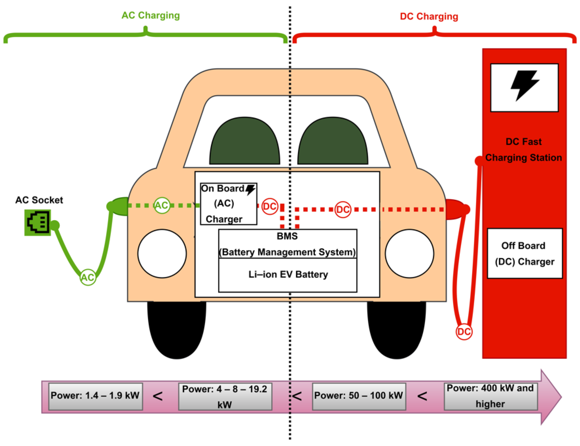
The conductive charging method consists of three parts, which are called the charging port/cable/coupler, the AC/DC rectifier, and the BMS (battery management system). Wired or conductive chargers are subcategorized as on-board (AC) or off-board (DC) types, which both have the ability to supply unidirectional and bidirectional power flows [20,21]. While unidirectional chargers simplify interconnection problems and limit hardware demand, bidirectional types provide power stabilization via controlled conversion of power and vehicle-to-grid (V2G) technology by battery energy injection [5,13]. Figure 4 shows the configuration of a conductive charging system with both AC and DC charging methods.
As can be seen in Figure 4, the charger is located on the inside in vehicles with an on-board structure. Therefore, AC power from the grid is supplied to the charging point or station and from there to the on-board charger, which makes a conversion via the embedded AC/DC rectifier and provides DC power to the battery. Thus, the on-board type is called an AC charger, since conversion happens inside the vehicle. With the off-board method, the charger is located outside the vehicle, and inside a charging station which converts AC power from grid to DC, and it supplies that DC power directly to the battery. Thus, the off-board type is called a DC charger [22,23], since conversion occurs outside the vehicle.

2.2. AC-DC Charging Levels and Standards

According to The Society of Automotive Engineers (SAE) J1772 standard [24], there are three power levels of charging [15,20,25]. Table 1 (data collected from [12,15,20,26]) indicates charging power levels according to the SAE J1772 standard. From Table 1, AC level 1 (with 230 V AC input for EU and 120 V for US) and AC level 2 (with 400 V AC input for EU and 240 V for US) deliver up to power of 1.9 kW and 19.2 kW, respectively. Depending on battery capacity, the charging time of an AC level 1 is between 11–36 h. Thus, this slow-type, single-phase charger is suitable for overnight residential charging. AC level 2 charging time is between 1–6 h. Hence, this is used to charge EVs, both privately and publicly, in places such as universities, shopping malls, hospitals, etc. [5,13]. AC charging relies on on-board chargers that have limited power ratings to reduce the weight and volume occupied on the EV. Off-board (DC) level 3 chargers are, instead, installed on the ground, and they are referred as ‘Fast-Chargers’. As the space occupied is often not a problem, higher charging rates can be obtained by DC fast-chargers, with typical power of 50–100 kW and, more recently, 350–400 kW and higher. With DC fast-charging technology, the charging time of EVs is reduced to 10–30 min, which is close to the refueling time for ICE vehicles [12,15,26].
Therefore, DC fast charging is more suitable for commercial or public charging places such as shopping malls, highway rest stops, and urban charging stations.

3. DC Fast Charging

3.1. Power Levels and Coupler Types of DC Fast-Charging

The existing literature describes quick, fast, and ultra-fast charging schemes, the power ratings of which are up to 120 kW. Lately, extreme fast charging (XFC), which can reach power levels around 350 kW and 400 kW, has been proposed. The power ratings of DC fast-chargers have been continually increasing in order to reduce charging time and provide better driving range capacity [4,14,15]. There are different standards based on the various power levels and connector types for DC fast-charging systems [15,22]. According to the SAE J1772 standard, there are three power levels of DC fast-charging. These are:
Level 1: 200–450 Vdc and 80 A, power up to 36 kW with 22 min charging time,
Level 2: 200–450 Vdc and 200 A, power up to 90 kW with 10 min charging time,
Level 3: 200–600 Vdc and 400 A, power up to 240 kW with less than 10 min charging time [9,20,23,27].
As mentioned above, coupler type is the second main parameter for defining standards for charging systems. Six different standards, together with proposed higher power levels for DC fast-charging systems can be seen in Table 2 (data collected from [28,29]).
In Table 2, there are four connector configurations (AA-BB-EE-FF) for DC fast-chargers with reference to the IEC (International Electrotechnical Commission) 62196-3 Standard [31]. Also, there are specific Tesla and ChaoJi configurations. The Japan-based CHAdeMO Association proposes configuration AA, with available power up to 400 kW, while China based GB/T implements configuration BB, with a power rating of 185 kW. Type 1 CCS (combined charging system, or combo) which is referred to as configuration EE, with a 200 kW power level, is available in North America, whereas Type 2 CCS, which is called configuration FF, with a 350 kW power level, has been adopted in Europe and Australia. A specific connector proposed by Tesla with power level of 250 kW can be used for both AC and DC charging at the same time. This unique aspect of the Tesla coupler has been developed for the sole use of Tesla EVs [9,14,15,22,27]. Also, a new standard, which is called ChaoJi, with 900 kW, has emerged with the collaboration of the CHAdeMO Association and the China Electricity Council, one which aims to raise the charging power further [28,37].

3.2. Status of the DC Fast-Charging Station

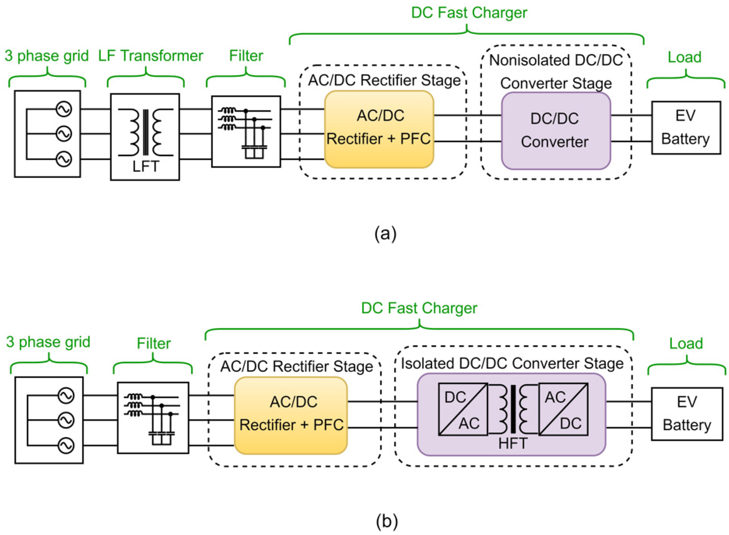
Galvanic isolation is required between the grid and the EV battery pack. There are two ways of creating galvanic isolation: using a low frequency transformer (LFT) between the grid and AC/DC stage (Figure 5a); and using a high frequency transformer (HFT) in the DC/DC stage (Figure 5b) [15,22,38,39]. Note that the two isolation options depicted in Figure 5 indicate a single module charger in order to keep the complexity low.
If the power requirement from the DC fast-charger increases, identical modules are connected in parallel to increase the output power of the system. Based on this application, LF and HF transformer configurations can be found in [15,22,38,39]. A filter connected at the input stage of the rectifier reduces the harmonic distortion of the current drawn by the rectifier itself. Mostly, LC or LCL filters are preferred due to their better performances, as compared to L filters [40,41,42].

3.3. DC Fast-Charging Station Architectures

All DC fast-charging station configurations consist of energy sources such as the grid, renewable energy sources (RESs) such as solar photovoltaic (PV) and wind, or energy storage systems (ESSs). RESs and ESSs reduce grids’ congestion at peak time, reducing the risk of load shedding [43] The fast-charging stations’ architectures are divided into two groups according to their method of integration into a common bus, one which enables charging and energy sharing between chargers, as shown in Figure 6.
These groups are called conventional AC or DC bus configurations, both of which can provide unidirectional or bidirectional power [5,15,22,25,28,44,45,46]. Alternatively, a combination of AC and DC bus-based architectures [43,47]. Unidirectional power flow structures reduce the complexity of hardware requirements and the frequency of interconnection problems, whereas bidirectional charging enables V2G, station-to-grid (S2G), and vehicle-to-vehicle (V2V) operations, together with battery energy injection back to the grid [5]. All charging station architectures contain the same components, but they use different power distribution methods (AC bus, DC bus, or combined bus). Figure 7 describes these architectures for fast-charging stations, considering the case of LFT isolation mentioned in Figure 5a.
In Figure 7a, the AC power is distributed through the bus. Thus, each device, such as the EV charger, RES such as PV, and the ESS, contains its own individual AC/DC rectification stages, which are connected to the common coupling point of the AC bus. The benefits of this method are technical maturity and the availability of switchgear and devices for protection. However, this method has higher cost and complexity due to the increased number of AC/DC conversion stages and the filter requirements for each unit after their rectification stages. Therefore, the efficiency of the AC network is low [15,22,44].
On the other hand, the conventional DC bus architecture in Figure 7b utilizes one central front-end AC/DC rectifier to build the DC bus. Thus, each device has a simpler power conversion stage, decreasing the cost of the system and increasing its efficiency. Moreover, the control schemes of a DC network system are simpler than those of AC networks. However, this method requires more complicated protection devices, since there are no well-established protection standards for grounding configuration, fault type, component specification and size in DC network systems [15,22,44].
Another method of distribution is the combination of AC and DC bus-based architecture as shown in Figure 7c. This hybrid architecture aims at combining the advantages of AC and DC networks. In this hybrid method, the grid, RESs and ESSs are connected to AC and DC busses by means of different converters in order to achieve simultaneous operation. A bidirectional converter, which is called an interlinked converter (ILC), set between the AC and DC busses, is a key piece of equipment for ensuring power exchange and energy balance between both sides, which are designed to work simultaneously, based on the load requirements. Thus, an ILC can operate in rectifier or inverter mode. The bidirectional DC/DC converters between EVs and the DC bus are responsible for DC fast charging/discharging with the help of a V2G, S2G or V2V operation [43,47].
The advantages of a DC network and/or an AC-and-DC combined network structure over the AC network makes them the best options for a DC fast-charging system. Designing a DC or hybrid bus-based fast-charging station with optimal choices for the AC/DC rectifier and the DC/DC converter stages is compulsory. Therefore, different conversion topologies will be discussed in the following section.

4. Classification of DC Fast-Charger Conversion Stages with Converters

In this section, both unidirectional and bidirectional chargers with different converter topology adaptations will be investigated based on their power flow direction.

4.1. AC/DC Rectifier Stage

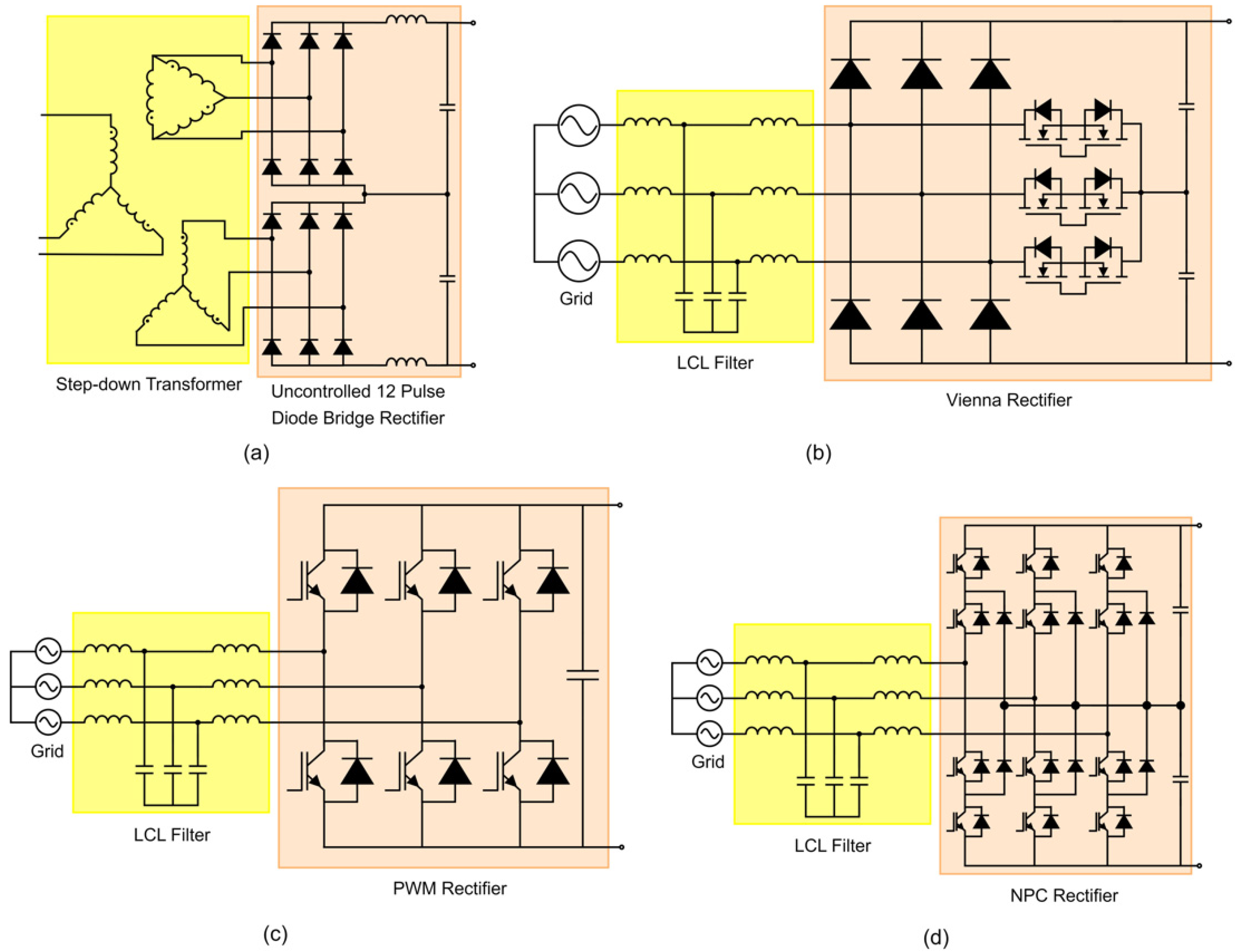
Front-end AC/DC rectifiers provide a high power factor, higher power density [48], and low current harmonic distortion on both AC and DC sides [28,41,49]. This aim can be achieved by shaping the current [44] and regulating output voltage [15]. Figure 8 shows the most common and commercially available AC/DC rectifiers, such as the 12-pulse diode bridge rectifier, the Vienna rectifier, the pulse width modulation (PWM) rectifier, and the neutral point clamped (NPC) rectifier [15,28,48,49].
Unidirectional power from the grid to the charger is supplied by the diode bridge and Vienna topologies, whereas PWM and NPC configurations are widely used for bidirectional operation [15,28,48,49].

4.1.1. Unidirectional AC/DC Rectifiers

The unidirectional AC/DC conversion stage is mostly formed by uncontrolled (diode bridge) rectifiers [26] or phase controlled (thyristor) line-commutated converters (LCCs) [17] and Vienna rectifiers [42].
An uncontrolled diode bridge rectifier, as shown in Figure 8a, is mostly preferred for the unidirectional rectifier stage of EV chargers because of its simplicity, cost-effective nature and robust potential configurations to create a common DC bus. This type of rectifier causes significant harmonic distortion, which requires active/passive filters [25]. In [44], a unidirectional 12-pulse active diode rectifier which has a conjunction with a three-level bidirectional buck-boost DC/DC converter to integrate an energy storage system and reduce peak demand from the grid is proposed for a 1.1 MW charging station prototype. The auxiliary voltage supply (AVS) is inserted to the midpoint of two six-pulse rectifiers to shape the input current of the AC/DC conversion stage, eliminate the harmonics, and improve power quality. Rectifier current is shaped into a triangular waveform for harmonic content. A variable frequency strategy which reduces voltage changes across DC link capacitors is applied to provide better DC/DC conversion. In [25], the same authors applied a virtual impedance control approach of a unified active LC filter into the same 12-pulse active diode rectifier prototype in [44] to control harmonic distortion of the rectifier. Injection of a virtual impedance (basically a current source) into the LC filter of the rectifier reduces AC side harmonics and shapes AC and DC currents and voltages. To have adjustable filter impedance and form current sources, two buck-boost converters are used. According to experimental results based on a 390 W setup prototype, the utilization of bidirectional buck-boost converters helps to interface with energy storage system and compensate DC side voltage ripples.
A Vienna rectifier, as seen in Figure 8b, is another popular unidirectional rectifier topology which is basically three-level converter with high power density [42,50,51,52,53,54], proposed by Prof. Johann W. Kolar [55,56,57,58]. If bidirectional power flow is not necessary, this topology is an excellent option for DC fast-charging systems because of its ability to reach an efficiency of 94–98% [28,49]. Since it is three-level solution, a Vienna rectifier contains all the benefits of multilevel converters, such as low switching frequency and low power losses, together with very low harmonic content [28,42,48,50,51]. Also, reduction in the size of the system can better be achieved with a Vienna rectifier, compared to NPC topology [50]. Even though the control complexity of the Vienna topology is more than that of diode or thyristor-based LLC rectifiers, it is less complex than that of other three-level rectifiers, due to the inclusion of only one active switch per phase. PFC is determined by the boost inductors at the input (filter) side [42]. In Figure 8b, when the switch is OFF, the energy is stored by the inductor. Then, when the switch is ON, the stored energy is transferred from the inductor to the load through the diodes. Also, there is no requirement of neutral point connection in this topology, which eliminates dead-time problems. However, there is still a need for balancing of capacitors’ voltages [42,50,51].
In [51], the three-level voltage vector of a Vienna rectifier is converted to a two-level vector plane. The proposed simulation method reduces midpoint fluctuations and improves power quality by applying space vector pulse width modulation (SVPWM) technique. Thus, it provides better dynamic and steady-state performance. Ref. [50] discusses different configurations of a Vienna rectifier for an EV fast-charging station by means of power factor, output power, harmonic content, efficiency, and reliability. The power loss comparison between the three Vienna topologies is made based on a full-load condition using different input voltages. Simulation results showed that topology three, which consists of two diodes and two controlled switches per phase, provides the best performance, with 99% efficiency compared to topology one, which includes six diodes and one switch per phase, and topology two, which comprises four diodes and two switches per phase, respectively.

4.1.2. Bidirectional AC/DC Rectifiers

There are numerous bidirectional AC/DC rectifier topologies in the literature. This section focusses on the pulse width modulated (PWM) rectifier [26] and the neutral point clamped (NPC) rectifier [15].
A PWM rectifier is basically a three-phase two-level voltage source converter (VSC), as shown in Figure 8c. This topology provides an easy controllability, high power factor, and low total harmonic distortion (THD), along with bidirectional energy flow [28,48,49]. To be able to transfer the power, the DC bus voltage must be at least 1.1 times the line-to-line peak input voltage in this type of VSC [59]. However, two-level PWM rectifiers do not supply as good a quality of output waveforms as does a three-level or multilevel rectifier [49]. To shape the current waveforms, which can be compatible with other three-level or multilevel converters, and to compensate the harmonics, a bulky input filter inductor is required [15,28,41].
In [59], a bidirectional active PWM rectifier which interfaces between a three-phase line-to-line 230Vrms grid and the bidirectional DC/DC converter is proposed to supply both active power exchange with the grid and compensation of the reactive power demand of the grid. An EV battery is connected to the DC bus through a DC/DC converter. Thus, while the output filter of the DC/DC converter supplies a smooth charging current, the ripple effects of the DC bus on the battery are also eliminated. This configuration has the capability to work under unbalanced and distorted grid conditions. The dynamic performance of the charger under different operating modes, such as pure active power flow (charging or discharging), pure reactive power compensation (inductive of capacitive), simultaneous charging/discharging, and reactive power compensation have been investigated. The reference grid currents are estimated by controlling VSC to produce the switching pulses for the PWM rectifier. According to the simulation results, the direction of the reference grid currents instantly reverses by the control without producing any spike. Also, the DC bus voltage stays at 400 V, while the THD of the grid current remains within 5% in all different operating scenarios.
An NPC rectifier is a three-level topology, as shown in Figure 8d [28,48,49] and, as such, has lower harmonics than do two-level inverters, together with reduced stresses on semiconductor devices [15]. Moreover, this topology creates a split DC bus, so that various loads can be fed by different voltages between neutral point and negative/positive bars of the DC bus [15,28,60]. However, this type of bipolar DC bus operation causes voltage imbalance on the DC output, as well as incompatibilities in the distribution of losses between different DC/DC converters [49]. For this reason, NPC topology requires appropriate and additional control methods and modulation techniques to balance the DC capacitors [49]. Also, the higher number of switching devices increases the cost of the converter [28,61].
In [60], a four-leg three-phase active NPC rectifier that is integrated between the grid and the DC bus is proposed and simulated for a 1.2MW charging station prototype. Instead of a separate DC/DC stage, an identical fourth leg, one which acts as a bidirectional DC/DC converter, is used. According to the experimental results based on 3.6 kW charging station prototype, the presence of a fourth leg provides fault-tolerant operation and eliminates the additional balancing circuit so that the rectifier can operate under any load condition. In [45], authors proposed a 240 kW bipolar DC bus charging station simulation prototype with a step-down isolation transformer at the grid side and an active NPC rectifier integrated with three-level non-isolated DC/DC converters to provide voltage balance control (VBC) on both the NPC and the three-level DC/DC converter sides. According to the 1.2 kW setup’s experimental results, their proposed coordinated VBC method provided faster balancing response and better performances in balancing the DC/DC bus voltages and improving the power quality than did the design in which VBC was only located at the NPC converter’s side. Also, the additional balancing circuit requirement is eliminated with this method.

4.1.3. Summary

The authors of [61] have carried out a comparison between Vienna, PWM, and NPC topologies in terms of efficiency, losses, and the cost/efficiency metrics in a PLECS/SpeedFit simulation environment under different operating frequencies. The results highlight that both Vienna and PWM rectifiers have the best trade-off between cost and efficiency. Although the PWM rectifier provides an easier controllability because of fewer components, as well as a 12% cost advantage over the Vienna topology, it still requires an electromagnetic interference (EMI) filter to lower the input current’s harmonic distortion. The efficiency of the Vienna, PWM and NPC topologies, which supply 22 kW output power for high power on-board chargers, are 98.95, 98.86, and 98.44, respectively, with the simulation parameters of 20 kHz switching frequency, 400 V AC input voltage, and 800 V DC output voltage. To sum up, the features and the comparison of AC/DC rectifier topologies for DC fast-chargers are listed in Table 3 (data collected from [12,15,48,49]), below.

4.2. DC/DC Converter Stage

4.2.1. Isolated and Non-Isolated DC/DC Converters

The DC/DC converter stage creates an interface between the AC/DC rectifier stage and the RES, ESS, or battery of the EVs, so that the provided intermediate DC voltage from the AC/DC rectifier can be regulated to charge the battery. According to the requirements for galvanic isolation explained above, DC/DC converters are classified as isolated or non-isolated [15,26]. Figure 9 shows the most common types of isolated DC/DC converters.
The LLC topology contains a high frequency (HF) transformer for galvanic isolation, and is created by two stages of power conversion, as can be seen in Figure 9a. The primary stage is a full-bridge type converter whose switching frequency is controlled to match the resonant frequency of the tank [15]. The secondary stage is the diode bridge rectifier. The resonant tank between them consists of reactive components, such as a resonant capacitor (Cr), a leakage inductor (Lr) and a magnetizing inductor (Lm) to provide phase shift between the voltage and current so that soft switching can be achieved. Soft switching methods such as zero voltage switching (ZVS) on the primary side switches, as well as zero current switching (ZCS) on the secondary side diodes, are the biggest advantages of an LLC resonant converter. Due to the ZVS capability of the LLC, turn-off switching losses and transformer losses are reduced [15,62,63]. Thus, the LLC resonant converter provides a higher efficiency than do the other conventional hard-switching converter topologies [63]. Also, the implementation of soft-switching methods helps to ensure better EMI performance. Moreover, the LLC configuration is suitable for high power applications because of the ability to achieve high power density, and it can provide a good performance over a wide input voltage rate [15,64].
However, the battery characteristics of an EV charger are nonlinear and depend on the charging profiles. The output voltage of the LLC converter with a passive load is mainly formed by the load current, while the output voltage of the battery depends on the state of the charge (SOC), and the charging profile of the battery. This wide range of operating modes with nonlinear loads and containing nonlinear resonant components make the LLC converter difficult to analyze. Especially in the case of a light load situation, it is hard to maintain a ZVS condition under a widely-adjustable regulated output voltage range because of the circulating nonlinear I-V characteristics in the resonant tank [15,63,64]. Therefore, the most important design consideration of an LLC converter is the ability to achieve soft-switching operation under the whole working range. In [64], an LLC converter prototype operating at a rate power of 3.3 kW applied to a li-ion battery charger with 98.2% efficiency is proposed. The authors investigated different operation modes of the LLC based on a step-by-step design method. According to their results, soft-switching capability under all operating conditions is guaranteed and the boost operation mode in the case of full load situations is preferred. In [63], a variable DC link method is applied to 1 kW power rated LLC converter. The results show that the DC link voltage always follows the battery voltage over a wide SOC range so that LLC converter always operates at the resonant frequency with maximum efficiency. To provide maximum efficiency, the circulating current in the resonant tank, which is composed of magnetizing inductor current and the turn-off currents of the switches, is minimized while still achieving ZVS. According to the results, 2.1% efficiency improvement at the heaviest load situation and 9.1% at the lightest load situation are obtained, respectively.
DAB topology, as shown in Figure 9b, contains high frequency (HF) transformers for galvanic isolation and voltage matching between primary and secondary sides. Both sides of the transformer are connected to two symmetrical full active bridge converters. While an auxiliary inductor serves as the energy storage device, transformer leakage inductance serves as the main power transfer element. By adjusting phase shift between the output voltages of the two active bridges, control of power flow is provided to the load. The benefits of a DAB converter are high efficiency, achievement of high-power density, bidirectional operation with a buck-boost feature, symmetric structure, low device stresses because of the usage of active components on both sides, and soft switching capability. Moreover, DAB provides a good performance at widely achievable output voltage range and high switching frequency operation because of the ZVS feature. This soft-switching capability also reduces the size of the filter. Therefore, switching losses are reduced [15,65,66].
However, DAB converters that use SiC-based power electronic components with high switching frequency are affected by parasitic leakage inductances and stray capacitances [67] on the currents and voltages of the transformer. The high leakage inductance of the transformer provides a wide ZVS range, but it also makes reactive power worse, thereby reducing the efficiency [15,68]. To decrease these undesirable parasitic effects, the value of the leakage inductance of the transformer must be reduced. To improve performance of the DAB converter under a wide operating range, different control schemes for power transmission, such as single-phase shift (SPS), extended phase shift (EPS), dual [65] phase shift (DPS), and triple phase shift (TPS), are investigated in [66]. According to the paper, SPS modulation requires solely one control degree, whereas EPS and DPS methods demand two control degrees. TPS modulation is a unified form of SPS, EPS, and DPS. Therefore, while there are no unified implementation standards for TPS, it is also the hardest implementation method, as compared to others. Based on this article, DPS control is the more applicable method, due to its relatively simple implementation and good performance.
The PSFB converter contains a high frequency (HF) transformer for galvanic isolation, and is created by two stages of power conversion, as can be seen in Figure 9c. The structure of the PSFB is, except for the absence of passive and resonant components, quite similar to the LLC topology in terms of having a full bridge converter on the primary side, and a diode bridge rectifier on the secondary side [48]. The advantages of the PSFB converter are ZVS soft-switching capability on the primary side, simple phase-shift PWM control, low EMI, and decreased current stress on the devices [15,69,70].
However, the secondary side operates with hard switching because of the diodes. Additionally, it has high voltage stress on the rectifying bridge and high circulating current in the primary side during the freewheeling period, both of which increase losses [71]. Turn-off loses on the primary side switches and reverse recovery losses on the secondary side diodes both reduce efficiency [15,69]. Moreover, the ZVS turn-on range is highly reliant on the load, especially when the battery current is low [15,69,70]. The cost and power density decrease due to the large output inductor [69]. In [72], a 50 kW PSFB converter is designed and simulated. The results highlight that the majority of the losses belong to the transformer, and that the model has 99% and 97.5% efficiencies at a full-load condition with 25 kHz and 50 kHz, respectively. The light-load condition, on the other hand, has a reduced efficiency due to increment of the switching losses.
Non-isolated DC/DC converters are used when the galvanic isolation is provided in any other stages of the system. Unlike isolated ones, non-isolated DC/DC converters do not contain an HF transformer. The most common non-isolated topologies are typical boost, buck, buck-boost, interleaved boost, modified buck-boost, three-level boost, flying capacitor converters, H-bridge, Cuk, Sepic with Luo etc. [15,73]. In [74], the authors cover an extensive review on unidirectional non-isolated high gain DC/DC converters for DC fast-charging. The comparison between several non-isolated bidirectional DC/DC converters for a charging station is carried out in [75,76]. The experiment resulted in [75] emphasizing that, while a half-bridge converter provides higher efficiency than do Cuk and Sepic/Luo converters because of the reduced number of devices and lower switch current stress, the efficiency of three-level bidirectional DC/DC converters is 2–3% higher than that of the half-bridge.

4.2.2. Summary

To sum up, the features and the main advantages/disadvantages of DC/DC converter topologies for DC fast-chargers are listed in Table 4 (data collected from [12,15,73]).

5. Future Research Trends

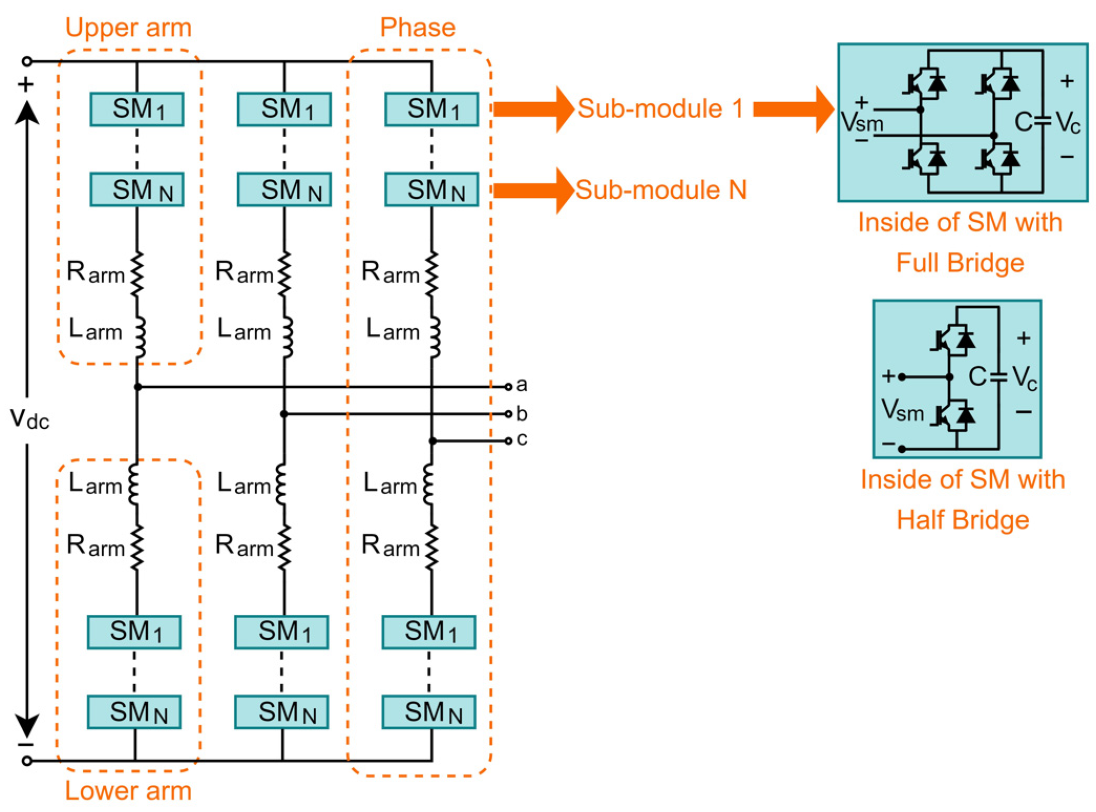
The power demands of a DC fast-charging station require a significant amount of power, which can easily exceed megawatts. Thus, recently, modular multilevel converters (MMCs) have become more popular compared to other multilevel topologies for medium/high voltage and high-power applications such as DC fast-chargers [77,78,79,80,81,82,83,84,85]. The reasons that MMCs are the preferred choice in medium/high voltage high-power applications include their modular and scalable structure, which can meet any voltage level requirements by using medium-voltage devices, as well as their lowering of voltage distortion and creation of more sinusoidal waveforms [78], superior harmonic performance [78], increased fault tolerability [84], and higher efficiency [86,87]. MMC is a type of cascaded topology of multilevel voltage source converter, but its operating process is different than that of other multilevel VSCs. As shown in Figure 10, the three-phase MMC comprises two symmetrical arms per phase, and N number of series-connected sub-modules (SMs), which could be either full-bridge or half-bridge rectifiers [87,88,89,90].
The output voltage of MMCs rely on the number of SMs; thus, N + 1 level output voltage is obtained with N number of SMs [85,87]. The modular configuration of MMC has the capability to continue operating, even some SMs fail, because of an ability to bypass faulty SMs in the case of defects without disruptions [85,89,90,91]. DC energy is divided, distributed and stored with low voltage capacitors in each SM in the MMC, unlike other multilevel VSCs that require series-connected high-voltage DC capacitors or a single and bulky DC capacitor which stores energy [89,91].
In [78], the authors carry out comparisons between the proposed MMC with half-bridge SM topologies and different multilevel topologies for EVs. The results highlight that an MMC with half bridge SMs has a fault tolerance, SOC balance control, and functions in charging/discharging modes, whereas a cascaded H-bridge (CHB) multilevel converter has only the latter two. Also, no reduction in switching frequency is detected in CHB topology. Ref. [79] suggests that MMC as a central rectifier connected between the grid and the MVDC for ultrafast charging provides a high controllability and high efficiency, while reducing the number of components and power losses. Despite all of its benefits, MMC has some drawbacks, such as an increased number of devices and control complexity [84]. In [80], a 500 kW series-parallel MMC (SP-MMC) is proposed for ultrafast EV charging. The simulation is validated in a PLECS environment to achieve conversion from medium-voltage low-frequency AC to low-voltage medium-frequency AC, along with the AC/DC/DC conversion. For control strategy, S-MMC voltage-current control, P-MMC DC link voltage control, and P-MMC voltage-current control subsystems have been utilized based on proportional integral (PI) and proportional resonant (PR) controllers. The results emphasize the effectiveness of the control strategy by indicating its capability of synthesizing medium-frequency voltages with acceptable harmonic distortion without creating serious effects on the input currents.
Recently, in [85], a modular push-pull converter (MPC), which was first introduced by M. Hagiwara and H. Akagi in [86,88,92] for battery energy storage systems, is applied for fast-charging of EVs, and simulations with 160 kW converter were conducted in a Matlab/Simulink environment. The aim of the utilization of the MPC topology rather than that of MMC in [85] is to achieve high power conversion via an increase in the output current instead of voltage. In MPC, current increment occurs via parallel connection of SMs, and by means of a three-phase transformer with a center-tap in the secondary windings, unlike the MMCs. Also, MPC has a nil DC component in the current of the transformer’s secondary windings. This can eliminate the extra inductors, which are rated for the full DC current which exists in MMC topology, and reduce the equipment cost. The utilization of modular converters seems to be set to increase in the near future.

6. Conclusions

This paper provides an overview of fast EV chargers, with several converter topologies. In the introductory part, different EV types and their positive and negative impacts were discussed. In Section 2, EV charging infrastructure, classification of different charging methods and AC/DC charging levels and standards were addressed. Section 3 covered DC fast-charging, together with its specifications and its benefits. Also, different distribution techniques, together with their advantages and disadvantages, have been examined, and the status of the DC fast-charging station, along with that of its components, has been presented. Classification of both AC/DC rectifier and DC/DC converter stages within the most popular converter topologies for DC fast-charging were deeply investigated in Section 4.
To clarify, the AC/DC stage is divided as unidirectional and bidirectional rectifiers while the DC/DC stage is divided into isolated and non-isolated converter subcategories, as shown in Figure 11. Table 3 and Table 4 provide summaries of different topologies in both stages, together with their features, advantages and disadvantages. The increasing popularity of the modular multilevel converter topologies (MMCs and MPCs) is highlighted in Section 5. Since MMC and MPC are bidirectional active-front-end (AFE) topologies, they are classified under the bidirectional AC/DC rectifiers section of Figure 11.

Author Contributions

This document is the result of a collaboration between the authors. Conceptualization, H.K. and P.T.; methodology, H.K.; writing—original draft preparation, H.K.; writing—review and editing, H.K.; visualization, H.K.; supervision, P.T. All authors have read and agreed to the published version of the manuscript.

Funding

This research has been conducted thanks to the scholarship for graduate studies provided by the Ministry of National Education, Republic of Turkey. The corresponding author is grateful for this scholarship.

Data Availability Statement

Not applicable.

Conflicts of Interest

The authors declare no conflict of interest.

References

  1. Situ, L. Electric vehicle development: The past, present & future. In Proceedings of the 2009 3rd International Conference on Power Electronics Systems and Applications (PESA), Hong Kong, China, 20–22 May 2009; pp. 1–3. [Google Scholar]
  2. Morimoto, M. Which is the first electric vehicle? Electr. Eng. Jpn. 2015, 192, 31–38. [Google Scholar] [CrossRef]
  3. Harikrishnan, R.; Sivagami, P.; Pushpavalli, M.; Rajesh, G.; Abirami, P.; Ram, M. Evolution of Electric Vehicle-A Review. In Proceedings of the 2023 5th International Conference on Smart Systems and Inventive Technology (ICSSIT), Tirunelveli, India, 23–25 January 2023; pp. 322–330. [Google Scholar]
  4. Ahmadi, M.; Mithulananthan, N.; Sharma, R. A review on topologies for fast charging stations for electric vehicles. In Proceedings of the 2016 IEEE International Conference on Power System Technology (POWERCON), Wollongong, NSW, Australia, 28 September–1 October 2016; pp. 1–6. [Google Scholar]
  5. Falvo, M.C.; Sbordone, D.; Bayram, I.S.; Devetsikiotis, M. EV charging stations and modes: International standards. In Proceedings of the 2014 International Symposium on Power Electronics, Electrical Drives, Automation and Motion, Ischia, Italy, 18–20 June 2014; pp. 1134–1139. [Google Scholar]
  6. Sanguesa, J.A.; Torres-Sanz, V.; Garrido, P.; Martinez, F.J.; Marquez-Barja, J.M. A review on electric vehicles: Technologies and challenges. Smart Cities 2021, 4, 372–404. [Google Scholar] [CrossRef]
  7. Sun, X.; Li, Z.; Wang, X.; Li, C. Technology development of electric vehicles: A review. Energies 2019, 13, 90. [Google Scholar] [CrossRef] [Green Version]
  8. Li, Z.; Khajepour, A.; Song, J. A comprehensive review of the key technologies for pure electric vehicles. Energy 2019, 182, 824–839. [Google Scholar] [CrossRef]
  9. Un-Noor, F.; Padmanaban, S.; Mihet-Popa, L.; Mollah, M.N.; Hossain, E. A comprehensive study of key electric vehicle (EV) components, technologies, challenges, impacts, and future direction of development. Energies 2017, 10, 1217. [Google Scholar] [CrossRef] [Green Version]
  10. Sadeghian, O.; Oshnoei, A.; Mohammadi-Ivatloo, B.; Vahidinasab, V.; Anvari-Moghaddam, A. A comprehensive review on electric vehicles smart charging: Solutions, strategies, technologies, and challenges. J. Energy Storage 2022, 54, 105241. [Google Scholar] [CrossRef]
  11. Mastoi, M.S.; Zhuang, S.; Munir, H.M.; Haris, M.; Hassan, M.; Usman, M.; Bukhari, S.S.H.; Ro, J.-S. An in-depth analysis of electric vehicle charging station infrastructure, policy implications, and future trends. Energy Rep. 2022, 8, 11504–11529. [Google Scholar] [CrossRef]
  12. Khalid, M.R.; Khan, I.A.; Hameed, S.; Asghar, M.S.J.; Ro, J.-S. A comprehensive review on structural topologies, power levels, energy storage systems, and standards for electric vehicle charging stations and their impacts on grid. IEEE Access 2021, 9, 128069–128094. [Google Scholar] [CrossRef]
  13. Habib, S.; Khan, M.M.; Abbas, F.; Sang, L.; Shahid, M.U.; Tang, H. A comprehensive study of implemented international standards, technical challenges, impacts and prospects for electric vehicles. IEEE Access 2018, 6, 13866–13890. [Google Scholar] [CrossRef]
  14. Suarez, C.; Martinez, W. Fast and ultra-fast charging for battery electric vehicles–a review. In Proceedings of the 2019 IEEE Energy Conversion Congress and Exposition (ECCE), Baltimore, MD, USA, 29 September–3 October 2019; pp. 569–575. [Google Scholar]
  15. Tu, H.; Feng, H.; Srdic, S.; Lukic, S. Extreme fast charging of electric vehicles: A technology overview. IEEE Trans. Transp. Electrif. 2019, 5, 861–878. [Google Scholar] [CrossRef]
  16. Kisacikoglu, M.C.; Bedir, A.; Ozpineci, B.; Tolbert, L.M. PHEV-EV Charger Technology Assessment with an Emphasis on V2G Operation; Oak Ridge National Lab (ORNL): Oak Ridge, TN, USA, 2012. [Google Scholar]
  17. Kumar, S.; Usman, A. A review of converter topologies for battery charging applications in plug-in hybrid electric vehicles. In Proceedings of the 2018 IEEE Industry Applications Society Annual Meeting (IAS), Portland, OR, USA, 23–27 September 2018; pp. 1–9. [Google Scholar]
  18. Shareef, H.; Islam, M.M.; Mohamed, A. A review of the stage-of-the-art charging technologies, placement methodologies, and impacts of electric vehicles. Renew. Sustain. Energy Rev. 2016, 64, 403–420. [Google Scholar] [CrossRef]
  19. Nour, M.; Chaves-Ávila, J.P.; Magdy, G.; Sánchez-Miralles, Á. Review of positive and negative impacts of electric vehicles charging on electric power systems. Energies 2020, 13, 4675. [Google Scholar] [CrossRef]
  20. Habib, S.; Khan, M.M.; Abbas, F.; Tang, H. Assessment of electric vehicles concerning impacts, charging infrastructure with unidirectional and bidirectional chargers, and power flow comparisons. Int. J. Energy Res. 2018, 42, 3416–3441. [Google Scholar] [CrossRef]
  21. Pradhan, R.; Keshmiri, N.; Emadi, A. On-Board Chargers for High-Voltage Electric Vehicle Powertrains: Future Trends and Challenges. IEEE Open J. Power Electron. 2023, 4, 189–207. [Google Scholar] [CrossRef]
  22. Ronanki, D.; Kelkar, A.; Williamson, S.S. Extreme fast charging technology—Prospects to enhance sustainable electric transportation. Energies 2019, 12, 3721. [Google Scholar] [CrossRef] [Green Version]
  23. Shaukat, N.; Khan, B.; Ali, S.; Mehmood, C.; Khan, J.; Farid, U.; Majid, M.; Anwar, S.; Jawad, M.; Ullah, Z. A survey on electric vehicle transportation within smart grid system. Renew. Sustain. Energy Rev. 2018, 81, 1329–1349. [Google Scholar] [CrossRef]
  24. SAE J1772; SAE Electric Vehicle and Plug in Hybrid Electric Vehicle Conductive Charge Coupler. 13 October 2017. Available online: https://www.sae.org/standards/content/j1772_201710/ (accessed on 22 May 2023).
  25. Bai, S.; Lukic, S.M. Unified active filter and energy storage system for an MW electric vehicle charging station. IEEE Trans. Power Electron. 2013, 28, 5793–5803. [Google Scholar] [CrossRef]
  26. Yilmaz, M.; Krein, P.T. Review of battery charger topologies, charging power levels, and infrastructure for plug-in electric and hybrid vehicles. IEEE Trans. Power Electron. 2012, 28, 2151–2169. [Google Scholar] [CrossRef]
  27. Rajagopalan, S.; Maitra, A.; Halliwell, J.; Davis, M.; Duvall, M. Fast charging: An in-depth look at market penetration, charging characteristics, and advanced technologies. In Proceedings of the 2013 World Electric Vehicle Symposium and Exhibition (EVS27), Barcelona, Spain, 17–20 November 2013; pp. 1–11. [Google Scholar]
  28. Saadaoui, A.; Ouassaid, M.; Maaroufi, M. Overview of Integration of Power Electronic Topologies and Advanced Control Techniques of Ultra-Fast EV Charging Stations in Standalone Microgrids. Energies 2023, 16, 1031. [Google Scholar] [CrossRef]
  29. Wang, L.; Qin, Z.; Slangen, T.; Bauer, P.; Van Wijk, T. Grid impact of electric vehicle fast charging stations: Trends, standards, issues and mitigation measures-an overview. IEEE Open J. Power Electron. 2021, 2, 56–74. [Google Scholar] [CrossRef]
  30. 2030.1.1-2021 IEEE Standard for Technical Specifications of a DC Quick and Bidirectional Charger for Use with Electric Vehicles. 18 February 2022. Available online: https://ieeexplore.ieee.org/document/9760299 (accessed on 22 May 2023).
  31. IEC 62196-3:2022 Plugs, Socket-Outlets, Vehicle Connectors and Vehicle Inlets—Conductive Charging of Electric Vehicles—Part 3: Dimensional Compatibility Requirements for DC and AC/DC Pin and Contact-Tube Vehicle Couplers. 19 October 2022. Available online: https://webstore.iec.ch/publication/59923 (accessed on 22 May 2023).
  32. CHAdeMO Protocol Development. Available online: https://www.chademo.com/technology/protocol-development (accessed on 22 May 2023).
  33. Available online: https://globalautoregs.com/participants/312-sgcc (accessed on 22 May 2023).
  34. Available online: https://www.chinesestandard.net/PDF.aspx/GBT20234.1-2011 (accessed on 22 May 2023).
  35. Available online: https://www.chinesestandard.net/PDF.aspx/GBT20234.3-2011 (accessed on 22 May 2023).
  36. Available online: https://main.spc.net.cn/ (accessed on 22 May 2023).
  37. Sharma, G.; Sood, V.K.; Alam, M.S.; Shariff, S.M. Comparison of common DC and AC bus architectures for EV fast charging stations and impact on power quality. ETransportation 2020, 5, 100066. [Google Scholar] [CrossRef]
  38. She, X.; Huang, A.Q.; Burgos, R. Review of solid-state transformer technologies and their application in power distribution systems. IEEE J. Emerg. Sel. Top. Power Electron. 2013, 1, 186–198. [Google Scholar] [CrossRef]
  39. Abu-Siada, A.; Budiri, J.; Abdou, A.F. Solid state transformers topologies, controllers, and applications: State-of-the-art literature review. Electronics 2018, 7, 298. [Google Scholar] [CrossRef] [Green Version]
  40. Dursun, M.; Döşoğlu, M.K. LCL filter design for grid connected three-phase inverter. In Proceedings of the 2018 2nd International Symposium on Multidisciplinary Studies and Innovative Technologies (ISMSIT), Ankara, Turkey, 19–21 October 2018; pp. 1–4. [Google Scholar]
  41. Dusmez, S.; Cook, A.; Khaligh, A. Comprehensive analysis of high quality power converters for level 3 off-board chargers. In Proceedings of the 2011 IEEE Vehicle Power and Propulsion Conference, Chicago, IL, USA, 6–9 September 2011; pp. 1–10. [Google Scholar]
  42. Channegowda, J.; Pathipati, V.K.; Williamson, S.S. Comprehensive review and comparison of DC fast charging converter topologies: Improving electric vehicle plug-to-wheels efficiency. In Proceedings of the 2015 IEEE 24th International Symposium on Industrial Electronics (ISIE), Buzios, Brazil, 3–5 June 2015; pp. 263–268. [Google Scholar]
  43. Acharige, S.S.; Haque, M.E.; Arif, M.T.; Hosseinzadeh, N.; Hasan, K.N.; Oo, A.M.T. Review of Electric Vehicle Charging Technologies, Standards, Architectures, and Converter Configurations. IEEE Access 2023, 11, 41218–41255. [Google Scholar] [CrossRef]
  44. Bai, S.; Yu, D.; Lukic, S. Optimum design of an EV/PHEV charging station with DC bus and storage system. In Proceedings of the 2010 IEEE Energy Conversion Congress and Exposition, Atlanta, GA, USA, 12–16 September 2010; pp. 1178–1184. [Google Scholar]
  45. Tan, L.; Wu, B.; Yaramasu, V.; Rivera, S.; Guo, X. Effective voltage balance control for bipolar-DC-bus-fed EV charging station with three-level DC–DC fast charger. IEEE Trans. Ind. Electron. 2016, 63, 4031–4041. [Google Scholar] [CrossRef]
  46. Alharbi, M.; Dahidah, M.; Pickert, V.; Yu, J. Comparison of SiC-based DC-DC modular converters for EV fast DC chargers. In Proceedings of the 2019 IEEE International Conference on Industrial Technology (ICIT), Melbourne, VIC, Australia, 13–15 February 2019; pp. 1681–1688. [Google Scholar]
  47. Franzese, P.; Patel, D.D.; Mohamed, A.A.; Iannuzzi, D.; Fahimi, B.; Risso, M.; Miller, J.M. Fast DC Charging Infrastructures for Electric Vehicles: Overview of Technologies, Standards, and Challenges. IEEE Trans. Transp. Electrif. 2023. [Google Scholar] [CrossRef]
  48. Sutar, A.; Patil, M. On the Advancements in DC Fast Charging Power Converters Technologies for Electric Vehicle. J. Act. Passiv. Electron. Devices 2021, 16, 93–108. [Google Scholar]
  49. Aretxabaleta, I.; De Alegria, I.M.; Andreu, J.; Kortabarria, I.; Robles, E. High-voltage stations for electric vehicle fast-charging: Trends, standards, charging modes and comparison of unity power-factor rectifiers. IEEE Access 2021, 9, 102177–102194. [Google Scholar] [CrossRef]
  50. Rajendran, G.; Vaithilingam, C.A.; Naidu, K.; Oruganti, K.S.P. Energy-efficient converters for electric vehicle charging stations. SN Appl. Sci. 2020, 2, 583. [Google Scholar] [CrossRef] [Green Version]
  51. Shuguang, L.; Jiang, J.; Cheng, G. Research on vector control strategy of three phase VIENNA rectifier employed in EV charger. In Proceedings of the 2019 Chinese Control and Decision Conference (CCDC), Nanchang, China, 3–5 June 2019; pp. 4914–4917. [Google Scholar]
  52. Ali, A.; Chuanwen, J.; Yan, Z.; Habib, S.; Khan, M.M. An efficient soft-switched vienna rectifier topology for EV battery chargers. Energy Rep. 2021, 7, 5059–5073. [Google Scholar] [CrossRef]
  53. Dalessandro, L.; Round, S.D.; Drofenik, U.; Kolar, J.W. Discontinuous space-vector modulation for three-level PWM rectifiers. IEEE Trans. Power Electron. 2008, 23, 530–542. [Google Scholar] [CrossRef]
  54. Leibl, M.; Kolar, J.W.; Deuringer, J. New current control scheme for the vienna rectifier in discontinuous conduction mode. In Proceedings of the 2014 IEEE Energy Conversion Congress and Exposition (ECCE), Pittsburgh, PA, USA, 14–18 September 2014; pp. 1240–1247. [Google Scholar]
  55. Bindra, A.; Keim, T. Exciting Advances in Power Electronics: APEC 2018 Divulges Latest Advances in Magnetics, Wide-Bandgap Devices, Vehicle Batteries, 3-D Packaging, and More. IEEE Power Electron. Mag. 2018, 5, 49–55. [Google Scholar] [CrossRef]
  56. Ramasamy, S.; Reddy, D.; Saravanan, S. Comparative Analysis of RBFN and Fuzzy-SVPWM Controller Based Boost Type Vienna Rectifier for 1kW Wind Energy Conversion System. J. Green Eng. 2018, 8, 177–200. [Google Scholar] [CrossRef]
  57. White, R.V. Packaging and Integration and the Future of Power Electronics [White Hot]. IEEE Power Electron. Mag. 2020, 7, 87–92. [Google Scholar] [CrossRef]
  58. Kolar, J.W.; Zach, F.C. A novel three-phase utility interface minimizing line current harmonics of high-power telecommunications rectifier modules. IEEE Trans. Ind. Electron. 1997, 44, 456–467. [Google Scholar] [CrossRef] [Green Version]
  59. Verma, A.; Singh, B. Three phase off-board bi-directional charger for EV with V2G functionality. In Proceedings of the 2017 7th International Conference on Power Systems (ICPS), Shivajinagar, India, 21–23 December 2017; pp. 145–150. [Google Scholar]
  60. Rivera, S.; Wu, B.; Kouro, S.; Yaramasu, V.; Wang, J. Electric vehicle charging station using a neutral point clamped converter with bipolar DC bus. IEEE Trans. Ind. Electron. 2014, 62, 1999–2009. [Google Scholar] [CrossRef]
  61. Cuma, M.U.; Savrun, M.M. Performance Benchmarking of Active-Front-End Rectifier Topologies Used in High-Power, High-Voltage Onboard EV Chargers. Çukurova Üni. Müh. Fak. Derg. 2021, 36, 1041–1050. [Google Scholar] [CrossRef]
  62. Yang, B.; Lee, F.C.; Zhang, A.J.; Huang, G. LLC resonant converter for front end DC/DC conversion. In Proceedings of the APEC. Seventeenth Annual IEEE Applied Power Electronics Conference and Exposition (Cat. No. 02CH37335), Dallas, TX, USA, 10–14 March 2002; pp. 1108–1112. [Google Scholar]
  63. Wang, H.; Dusmez, S.; Khaligh, A. Maximum efficiency point tracking technique for $ LLC $-based PEV chargers through variable DC link control. IEEE Trans. Ind. Electron. 2014, 61, 6041–6049. [Google Scholar] [CrossRef]
  64. Deng, J.; Li, S.; Hu, S.; Mi, C.C.; Ma, R. Design methodology of LLC resonant converters for electric vehicle battery chargers. IEEE Trans. Veh. Technol. 2013, 63, 1581–1592. [Google Scholar] [CrossRef]
  65. Zhao, B.; Song, Q.; Liu, W.; Sun, Y. Overview of dual-active-bridge isolated bidirectional DC–DC converter for high-frequency-link power-conversion system. IEEE Trans. Power Electron. 2013, 29, 4091–4106. [Google Scholar] [CrossRef]
  66. Kheraluwala, M.; Gascoigne, R.W.; Divan, D.M.; Baumann, E.D. Performance characterization of a high-power dual active bridge DC-to-DC converter. IEEE Trans. Ind. Appl. 1992, 28, 1294–1301. [Google Scholar] [CrossRef]
  67. Harada, K.; Ninomiya, T.; Kakihara, H. Effects of stray capacitances between transformer windings on the noise characteristics in switching power converters. In Proceedings of the 1981 IEEE Power Electronics Specialists Conference, Boulder, CO, USA, 29 June–3 July 1981; pp. 112–123. [Google Scholar]
  68. Khalid, U.; Khan, M.M.; Xiang, Z.; Jianyang, Y. Bidirectional modular Dual Active Bridge (DAB) converter using multi-limb-core transformer with symmetrical LC series resonant tank based on cascaded converters in solid state transformer (SST). In Proceedings of the 2017 China International Electrical and Energy Conference (CIEEC), Beijing, China, 25–27 October 2017; pp. 627–632. [Google Scholar]
  69. Safayatullah, M.; Elrais, M.T.; Ghosh, S.; Rezaii, R.; Batarseh, I. A comprehensive review of power converter topologies and control methods for electric vehicle fast charging applications. IEEE Access 2022, 10, 40753–40793. [Google Scholar] [CrossRef]
  70. Zhou, K.; Wu, Y.; Wu, X.; Sun, Y.; Teng, D.; Liu, Y. Research and Development Review of Power Converter Topologies and Control Technology for Electric Vehicle Fast-Charging Systems. Electronics 2023, 12, 1581. [Google Scholar] [CrossRef]
  71. Chakraborty, S.; Vu, H.-N.; Hasan, M.M.; Tran, D.-D.; Baghdadi, M.E.; Hegazy, O. DC-DC converter topologies for electric vehicles, plug-in hybrid electric vehicles and fast charging stations: State of the art and future trends. Energies 2019, 12, 1569. [Google Scholar] [CrossRef] [Green Version]
  72. Hassanzadeh, N.; Yazdani, F.; Haghbin, S.; Thiringer, T. Design of a 50 kw phase-shifted full-bridge converter used for fast charging applications. In Proceedings of the 2017 IEEE Vehicle Power and Propulsion Conference (VPPC), Belfort, France, 11–14 December 2017; pp. 1–5. [Google Scholar]
  73. Vishnuram, P.; Bajaj, M.; Khurshaid, T.; Nauman, A.; Kamel, S. A comprehensive review on EV power converter topologies charger types infrastructure and communication techniques. Front. Energy Res. 2023, 11, 1103093. [Google Scholar] [CrossRef]
  74. Venugopal, R.; Balaji, C.; Savio, A.D.; Narayanamoorthi, R.; AboRas, K.M.; Kotb, H.; Ghadi, Y.Y.; Shouran, M.; Elgamli, E. Review on unidirectional non-isolated high gain DC-DC converters for EV sustainable DC fast charging applications. IEEE Access 2023. [Google Scholar] [CrossRef]
  75. Du, Y.; Zhou, X.; Bai, S.; Lukic, S.; Huang, A. Review of non-isolated bi-directional DC-DC converters for plug-in hybrid electric vehicle charge station application at municipal parking decks. In Proceedings of the 2010 Twenty-Fifth Annual IEEE Applied Power Electronics Conference and Exposition (APEC), Palm Springs, CA, USA, 21–25 February 2010; pp. 1145–1151. [Google Scholar]
  76. Tank, S.B.; Manavar, K.; Adroja, N. Non-isolated bi-directional DC-DC converters for plug-in hybrid electric vehicle charge station application. In Proceedings of the Emerging Trends in Computer & Electrical Engineering (ETCEE 2015), Rajkot, India, 13–14 March 2015. [Google Scholar]
  77. Camurca, L.; Pereira, T.; Hoffmann, F.; Liserre, M. Analysis, Limitations, and Opportunities of Modular Multilevel Converter-Based Architectures in Fast Charging Stations Infrastructures. IEEE Trans. Power Electron. 2022, 37, 10747–10760. [Google Scholar] [CrossRef]
  78. Hariri, R.; Sebaaly, F.; Kanaan, H.Y. A review on modular multilevel converters in electric vehicles. In Proceedings of the IECON 2020 The 46th Annual Conference of the IEEE Industrial Electronics Society, Singapore, 18–21 October 2020; pp. 4987–4993. [Google Scholar]
  79. Camurca, L.; Langwasser, M.; Zhu, R.; Liserre, M. Future MVDC applications using modular multilevel converter. In Proceedings of the 2020 6th IEEE International Energy Conference (ENERGYCon), Gammarth, Tunisia, 28 September–1 October 2020; pp. 1024–1029. [Google Scholar]
  80. Rodríguez, C.; Vidal, C.; Barros, R.; Díaz, M.; Rajendran, S. Control of an Ultrafast Electric Vehicle Charger based on a Series-Parallel Modular Multilevel Converter. In Proceedings of the 2022 Second International Conference on Sustainable Mobility Applications, Renewables and Technology (SMART), Lazio, Italy, 23–25 November 2022; pp. 1–6. [Google Scholar]
  81. Balachandran, A. Battery Integrated Modular Multilevel Converter Topologies for Automotive Applications; Linköping University Electronic Press: Linköping, Sweden, 2023. [Google Scholar]
  82. Rubio, F.; Pereda, J.; Rojas, F.; Poblete, P. Hybrid Sorting Strategy for Modular Multilevel Converters with Partially Integrated 2nd Life Battery Energy Storage Systems for fast EV charging. In Proceedings of the 2022 IEEE 7th Southern Power Electronics Conference (SPEC), Nadi, Fiji, 5–8 December 2022; pp. 1–7. [Google Scholar]
  83. Quraan, M.; Abu-Khaizaran, M.; Sa’ed, J.; Hashlamoun, W.; Tricoli, P. Design and control of battery charger for electric vehicles using modular multilevel converters. IET Power Electron. 2021, 14, 140–157. [Google Scholar] [CrossRef]
  84. Atanalian, S.; Al-Haddad, K.; Zgheib, R.; Kanaan, H.Y. A review on electric vehicles battery chargers and ac/dc converters for fast charging stations. In Proceedings of the 2021 IEEE 3rd International Multidisciplinary Conference on Engineering Technology (IMCET), Beirut, Lebanon, 8–10 December 2021; pp. 43–48. [Google Scholar]
  85. Kilicoglu, H.; Arya, H.; Das, M.; Tricoli, P. A New High-power Charging Points for Battery Electric Vehicles with Modular Push-pull Converters. In Proceedings of the 2022 International Symposium on Power Electronics, Electrical Drives, Automation and Motion (SPEEDAM), Sorrento, Italy, 22–24 June 2022; pp. 581–586. [Google Scholar]
  86. Hagiwara, M.; Akagi, H. Control and experiment of a modular push-pull PWM converter for a battery energy storage system. In Proceedings of the 2014 International Power Electronics Conference (IPEC-Hiroshima 2014-ECCE ASIA), Hiroshima, Japan, 18–21 May 2014; pp. 2323–2329. [Google Scholar]
  87. Kurtoğlu, M.; Eroğlu, F.; Arslan, A.O.; Vural, A.M. Modular multilevel converters: A study on topology, control and applications. In Proceedings of the 2018 5th International Conference on Electrical and Electronic Engineering (ICEEE), Istanbul, Turkey, 3–5 May 2018; pp. 79–84. [Google Scholar]
  88. Hagiwara, M.; Akagi, H. A battery energy storage system with a modular push-pull PWM converter. In Proceedings of the 2012 IEEE Energy Conversion Congress and Exposition (ECCE), Raleigh, NC, USA, 15–20 September 2012; pp. 747–754. [Google Scholar]
  89. Mishra, P.; Bhesaniya, M.M. Comparison of total harmonic distortion of modular multilevel converter and parallel hybrid modular multilevel converter. In Proceedings of the 2018 2nd International Conference on Trends in Electronics and Informatics (ICOEI), Tirunelveli, India, 11–12 May 2018; pp. 890–894. [Google Scholar]
  90. Akbar, S.M.; Hasan, A. Review of high voltage DC/DC modular multilevel converters. In Proceedings of the 2018 15th International Conference on Smart Cities: Improving Quality of Life Using ICT & IoT (HONET-ICT), Islamabad, Pakistan, 8–10 October 2018; pp. 46–50. [Google Scholar]
  91. Deng, F.; Liu, D.; Wang, Y.; Wang, Q.; Chen, Z. Modular multilevel converters based variable speed wind turbines for grid faults. In Proceedings of the IECON 2016-42nd Annual Conference of the IEEE Industrial Electronics Society, Florence, Italy, 23–26 October 2016; pp. 2420–2425. [Google Scholar]
  92. Hagiwara, M.; Akagi, H. Experiment and simulation of a modular push–pull PWM converter for a battery energy storage system. IEEE Trans. Ind. Appl. 2013, 50, 1131–1140. [Google Scholar] [CrossRef]
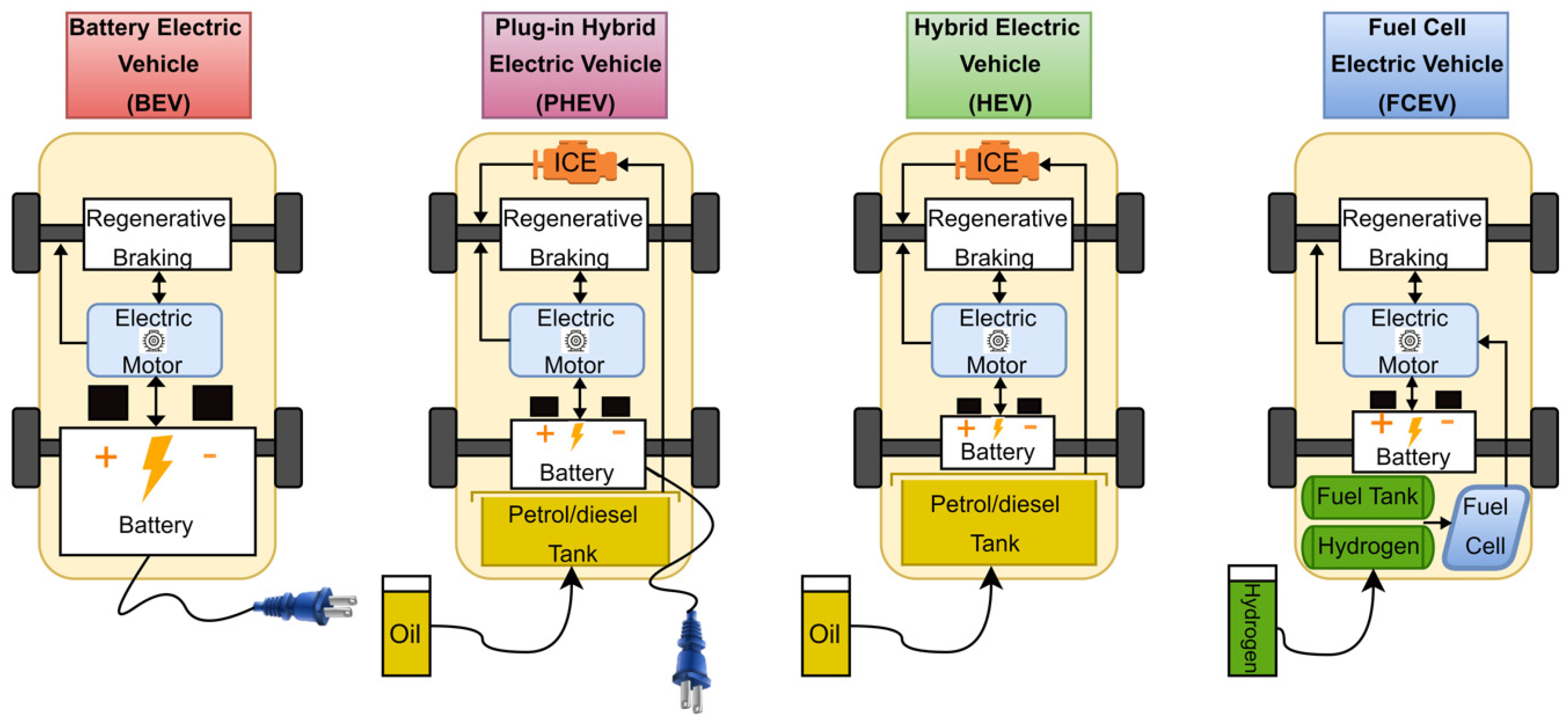
Figure 1. The basic diagrams of four types of EVs and their operation principles.
Energies 16 05204 g001
Figure 2. The basic concept of an EV charger.
Energies 16 05204 g002
Figure 3. Classification of EV charging methods.
Energies 16 05204 g003
Figure 4. Conductive charging system with both AC and DC charging methods.
Energies 16 05204 g004
Figure 5. Block diagram of DC fast-charger power conversion stages with: (a) LFT configuration; and (b) SST-based HFT configuration.
Energies 16 05204 g005
Figure 6. The classification of DC fast-charging station architectures.
Energies 16 05204 g006
Figure 7. Block diagrams of DC fast-charging station architectures: (a) AC bus configuration; (b) DC bus configuration; (c) Combination of AC and DC bus-based configurations.
Energies 16 05204 g007
Figure 8. The most common AC/DC rectifiers: (a) 12-pulse diode bridge rectifier; (b) Vienna rectifier; (c) PWM rectifier; (d) NPC rectifier.
Energies 16 05204 g008
Figure 9. The most common DC/DC converters: (a) LLC resonant converter; (b) DAB converter; (c) PSFB converter.
Energies 16 05204 g009
Figure 10. The structure of a three-phase MMC with full and half bridges.
Energies 16 05204 g010
Figure 11. Classification of the AC/DC and DC/DC converters covered in this paper.
Energies 16 05204 g011
Table 1. Charging power levels of the SAE J1772 standard.
Types of Power LevelsLocation for ChargerTypical UseLevel of Power
(P: kW)
EV Type, Time of Charging (hours)
Level 1 (AC): Convenient
Vac: 230 (EU)
Vac: 120 (US)
Single phase
On-board
ResidentialP: 1.4
(12 A)
P: 1.9
(20 A)
PHEVs (5–15 kWh)
4 to 11
EVs (16–50 kWh)
11 to 36
Level 2 (AC): Main
Vac: 400 (EU)
Vac: 240 (US)
Single or three-phase
On-board
Residential and workplace
(Privately and publicly charging)
P: 4
(17 A)
P: 8
(32 A)
P: 19.2
(80 A)
PHEVs (5–15 kWh)
1 to 4
EVs (16–30 kWh)
2 to 6
EVs (3 to 50 kWh)
2 to 3
Level 3 (DC): Fast
(208–600
Vac or Vdc)
Three-phase
Off-board
Station
(Publicly and commercially charging)
P: 50
P: 100
EVs (20–50 kWh)
0.4 to 1
0.2 to 0.5
Table 2. DC fast-charging standards.
StandardCHAdeMOGB/TCCS Type 1CCS Type 2TeslaChaoJi
Compliant StandardsIEEE 2030.1.1 [30]
IEC 62196-3 [31]
(Configuration AA)
IEC 62196-3 [31]
(Configuration BB)
SAE J1772 [24]
IEC 62196-3 [31]
(Configuration EE)
IEC 62196-3 [31]
(Configuration FF)
No related itemsCHAdeMO [32] and GB/T [33,34,35,36] (IEC and CCS is ongoing)
Maximum Voltage (V)10007506009005001500
Maximum Current (A)400250400400631600
Maximum Power (kW)400185200350250900
V2X FunctionYesNoNoNoUnknownYes
Table 3. Comparison of AC/DC rectifier topologies.
Features12-Pulse Diode BridgeViennaPWMNPC
Number of diodes12606
Number of switches06612
Bidirectional power flowNoNoYesYes
Harmonic contentLowVery lowLowVery low
Control complexityLowModerateLowHigh
Cost and sizeModerateModerate LowHigh
EfficiencyLow High Moderate High
PF RangeLowLimited High High
Table 4. Comparison of DC/DC rectifier topologies.
ConvertersIsolatedDiodes/SwitchesAdvantages/Disadvantages
LLC resonantYes4/4Reduced losses thanks to soft switching capability.
Complex control. Hard to maintain ZVS in case of light load condition.
DABYes0/8Good performance at a widely achievable output voltage range.
Requires an appropriate control scheme to increase efficiency by creating a balance between reactive power and ZVS.
PSFBYes4/4Simple phase-shift PWM control, low EMI, decreased current stress on devices.
Hard-switching on the secondary side. High losses, low efficiency.
BoostNo0/2Low control complexity.
Current and voltage capabilities are limited.
Buck-boostNo0/2Operation in both buck and boost modes.
High output current ripple, increased size of the filter capacitor while operating discontinuously in the boost mode.
Interleaved boostNo0/6Low current ripple with increased current capability, simple control, modularity.
Limited voltage capability.
Bidirectional three-level boostNo0/4Improved voltage capability, low charging current ripples.
Large circulating currents, non-modularity.
Flying capacitorNo0/4Improved voltage capability, modularity.
Limited short circuit protection.
H-bridgeNo0/4Reduced voltage stress across the switches. Maintaining the SOC as the desired value.
Increase in the RMS and average currents of inductor and switches.
Disclaimer/Publisher’s Note: The statements, opinions and data contained in all publications are solely those of the individual author(s) and contributor(s) and not of MDPI and/or the editor(s). MDPI and/or the editor(s) disclaim responsibility for any injury to people or property resulting from any ideas, methods, instructions or products referred to in the content.