Article

Influence of Different Redevelopment Measures on Water–Oil Immiscible Displacement and Mechanism Analysis

1
College of Civil Engineering, Xi’an Shiyou University, Xi’an 710065, China
2
Downhole Service Corporation, PetroChina Jidong Oilfield Company, Tangshan 063200, China
3
Chengdu Xingrong Environmental Co., Ltd., Chengdu 610040, China
4
Operating Area of Luliang Oilfield, Xinjiang Oilfield Company, Karamay 834000, China
*
Author to whom correspondence should be addressed.
Energies 2023, 16(13), 5047; https://doi.org/10.3390/en16135047
Submission received: 3 May 2023 / Revised: 23 June 2023 / Accepted: 27 June 2023 / Published: 29 June 2023
(This article belongs to the Section H1: Petroleum Engineering)

Abstract

:
Understanding the two-phase displacement behaviors of oil and water in porous media under different reservoir development modes for enhanced oil recovery is essential. In this paper, the influence of development measures, such as increasing the injection rate, changing the inlet/outlet position, increasing the water viscosity, and reducing the surface tension coefficient, on oil–water dynamic behaviors was studied using a numerical simulation based on the study of the formation of a high-water-cut channel by water flooding at different injection rates. The results show that blockage and restart occur during displacement in the pore–throat channel and during staggered displacement in different pore channels. With an increase in the injection rate, the recovery increases first and then decreases. All the different development measures can increase the swept area and recovery factor. The recovery factor increases significantly by reducing the surface tension coefficient at medium/high injection rates (≥0.01 m/s) and by increasing the viscosity of the water at low injection rates (<0.01 m/s). The numerical simulation study preliminarily revealed the influence of different development measures on displacement behaviors in the pore model. It thus provides theoretical support for understanding the law of oil and water movement in reservoirs.

1. Introduction

Water flooding is a cost-efficient secondary recovery method in oil and gas resource development. The displacement behaviors of water in rock pores include complex physical processes, such as viscous fingering, capillary fingering, and stable displacement, and they affect the oil recovery factor [1]. Therefore, the study of water flooding behaviors in pores is significant for understanding residual oil occurrence and distribution and the producing mechanism.
For flow behaviors in porous media, different scholars have studied groundwater pollution [2,3], carbon dioxide storage [4], oil and gas resource development [5,6,7], and underground hydrogen storage [8,9] using numerical simulations and experiments. It is difficult to experimentally change the core porosity, pore size, wetting angle, etc. [10,11,12]. At the same time, the numerical simulation method is increasingly used to study pore-scale multiphase flow due to its low resource consumption, controllable physical parameters, etc. [13,14,15,16]. At the pore scale, researchers have developed various methods to model two-phase flow in porous media. These methods primarily include the lattice Boltzmann method (LBM) [17,18,19], Pore Network Models (PNMs) [20,21], the grid-independent Smoothed Particle Hydrodynamics method (SPH) [22], Phase-Field methods [23], the volume-of-fluid (VOF) [5,24] method, and the level-set method [25]. de Castro et al. [26] used different pore morphologies to simulate a set of PNM flows and found that PNM provides accurate predictions of the flow of both Newtonian and shear-thinning fluids provided that the appropriate pore shape is used. Yu and Leung [27] proposed a robust simulation framework based on the level-set method. This model is useful for simulating multiphase multi-component interphase mass transfer in porous media. Liu et al. [28,29,30] used the lattice Boltzmann method to study the immiscible displacement between carbon dioxide and water, and they analyzed the influence of wall wettability, the two-phase viscosity ratio, capillary number (Ca), etc., on the displacement effect. Due to the VOF method’s ability to capture the flow interface by defining a volume function [31], it has yielded good simulation results in the study of immiscible two-phase flow in various fields, including mud flow [32], carbon dioxide storage [33,34], ocean engineering [35,36], and petroleum engineering [13,37,38]. Iyi et al. used the volume-of-fluid (VOF) model to simulate the process of oil–water two-phase transport in two-dimensional porous media, considering the effects of temperature, wetting angle, and surface tension. Their results showed that the displacement behaviors of the oil-wet system and water-wet system are greatly affected by the oil concentration, and oil recovery can be enhanced by changing the wettability from the oil-wet to water-wet states [13]. Based on the experimental measurement of core physical properties, Minakov et al. [37] used the VOF method for the numerical simulation of nanofluid displacement to study the effects of nanoparticle concentration, nanoparticle size, fluid velocity, oil viscosity, and core permeability on nanofluid displacement efficiency. Peng et al. [24] used the coupled volume-of-fluid and level-set method (VOSET) for a water injection simulation in a pore model to analyze the effects of the displacement rate and wettability on oil recovery. Lenormand et al. studied the water flooding process in two-dimensional porous media. They established a phase diagram to distinguish viscous, capillary fingering, and stable displacement modes according to the capillary number and viscosity ratio [15]. Patel et al. [16] simulated multiphase flow in two porous structures (repeated single pores and a random multi-pore arrangement). It was found that the residual oil saturation at different capillary numbers showed an opposite trend. Michels et al. simulated the flow in 2D (two-dimensional) and 3D (three-dimensional) porous rocks. It was found that, in the 2D model, the low-velocity effect of fluid at a low Ca value provided better conditions for fluid redistribution, resulting in a higher non-wetting fluid saturation; in the 3D model, more wetting fluid was captured due to a lower Ca value under the effect of the geometry of porous media [14].
The above research focuses on multiphase flow in porous media from heterogeneity, wettability, the wetting angle, etc. We have obtained rich research results on micro-displacement behaviors. However, re-displacement after the formation of a high-water-cut channel following water flooding in micro-pore media is seldom studied. Thus, the hydrodynamic behaviors of water flooding in porous media at different injection rates were studied using a numerical simulation first, and we accordingly discussed the hydrodynamic behaviors of oil in the micro-pore structure during redevelopment by increasing the injection rate and changing the inlet/outlet.

2. Mathematical Model

The mass conservation equation and momentum conservation equation are described by the Navier–Stokes (N-S) equation, while the volume fraction equation was used to track the distribution of oil and water in the grid. The equations are as follows:
· u = 0 ,
ρ u t + · ρ u u = p + · μ u + u T + ρ g + F ,
where u is the velocity vector, ρ is the density, g is the gravity acceleration, t is time, and p is the pressure. The coefficient of kinetic viscosity is μ . F represents the surface tension force.
In the VOF method, the volume indicator α is used to characterize the distribution of two-phase fluids in the computational region. When the computational cell contains the oil–water mixture, α is distributed between 0 and 1. The advection equation for the volume indicator α is written as follows:
α t + · u α = 0 ,
Equation (4) was used to approximate the surface tension force per unit volume in the momentum equation:
F = σ κ n ,
where κ represents the curvature of the interface computed using the local gradients of the interface normal, and n is the unit normal vector of the interface. The interfacial tension between oil and water is σ .
The flow was laminar due to the low injection rate, and the above equations were discretized using the finite volume method. This mathematical model is widely used in the numerical simulation of micro-scale oil–water two-phase flow in pores [13,37,38].

3. Physical Model, Parameter, and Case Settings

3.1. Physical Model

Figure 1 depicts the physical model of the microporous media used in the numerical simulation. It is important to note that the porous medium model was derived from a CT scanning image. By identifying the holes in the CT scanning grayscale, we obtained the microscopic physical model of the porous medium. The microscopic pore physical model measures 0.004 m in length and 0.0033 m in width, and it features multiple micron-scale interconnected pore–throat channels. To investigate the impact of changing the injection inlet position on oil–water two-phase behavior, two injection inlets were positioned on the upper and left sides, and two outlets were positioned on the right and lower sides of the physical model.
A grid independence study was conducted in Table 1 to verify the results’ independence from the mesh resolution. Subsequently, the magnitudes of the observation velocities were compared across varying cell numbers. The simulation encompassed a total of 105,118 cells. Moreover, this paper utilized the interFoam solver from the OpenFOAM open-source fluid mechanics codebase for numerical simulation research. The numerical simulation results obtained using this solver are consistent with the experimental results [5,39].

3.2. Parameter and Boundary Settings

During the numerical simulation, unless otherwise specified, the density of the water was set to 1000 kg/m3, the density of the oil was set to 800 kg/m3, the viscosity ratio of oil to water was 10, the dynamic viscosity of the water was 0.001 m2/s, and the tension coefficient of the oil–water interface was 0.07 kg·m−2.
The residuals of physical quantities, such as velocity, pressure, and alpha, were set to 10−6 during the calculation process, and the maximum Courant number was set to 0.3. The settings of the numerical boundary conditions are shown in Table 2.

3.3. Case Settings

A microporous physical model was investigated, and its size is shown in Figure 1. To evaluate the influence of different injection velocities on enhanced oil recovery (EOR) and phase behavior in the pore-scale porous model, five cases with varying velocities were investigated. Initially, the porous media were saturated with oil. Next, water was injected from the inlet of the model, and oil flowed out from the outlet until the outlet continuously discharged water for a prolonged period, while the oil–water phase in the porous media remained unchanged. In Table 3, cases 6–25 focused on the numerical simulation of displacement by increasing the injection rate, changing the inlet/outlet positions, reducing the interfacial tension coefficient, reducing the viscosity of the water, etc., based on the water flooding results of cases 1–5. For cases 16–20, it was assumed that the water–oil phase remained immiscible, even when the surface tension was reduced.

4. Results and Discussion

4.1. Instantaneous Oil–Water Dynamic Behaviors

4.1.1. Oil–Water Two-Phase Distribution

Figure 2 shows the distribution of oil and water in various porous regions and the position of the oil–water interface at different times, namely, (a) 0.58 s, (b) 0.685 s, (c) 0.795 s, (d) 0.9 s, (e) 1.085 s, and (f) 1.22 s, with an injection rate of 0.003 m/s. Figure 2a,b indicate that, from 0.58 s to 0.685 s, the oil–water interface moves along the throat from Point a to Point b, and water flooding stops at Point b, which is roughly in the area connecting the throat and pore, due to blockage. Figure 2b,c indicate that displacement starts at Point c and moves along Throats ce and cd at 0.685 s, and the oil–water interface is blocked at Points d and e at 0.795 s. Figure 2c–f show that displacement proceeds in different throats from 0.795 s to 1.22 s, especially in Throats bg and bf at 0.9 s, in Throats fi and fh at 1.085 s, and in Throats ij and ik thereafter. Over time, the swept area increases. The oil–water interface remains at the junction of the throat and pore at the aforementioned times, with staggered displacement in different throats, resulting in blockage and the re-start of the oil–water interface in the throats. To clarify the mechanism of this phenomenon, a theoretical explanation is provided in Figure 3.
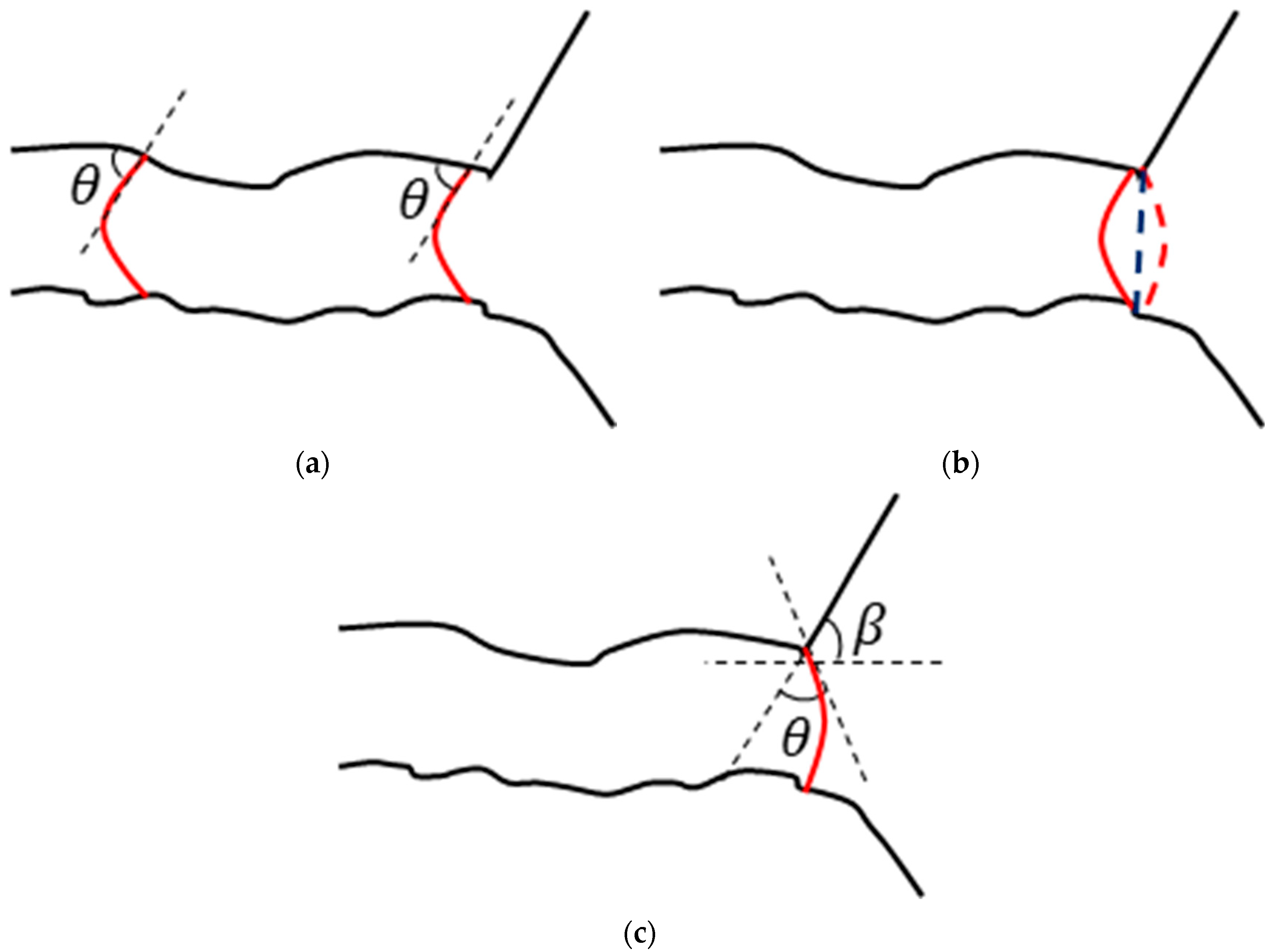
The surface tension coefficient can be calculated theoretically using Equation (1). During displacement in the throats, only the pore–throat radius changes and not the interfacial tension coefficient, σ , or the wetting angle, θ . However, the change in the pore–throat radius is so small that the water–oil interfacial tension changes insignificantly. As shown in Figure 3a, the oil–water interfacial tension is greater than 0 at a wetting angle of 45°, indicating that the capillary force is consistent with the water flooding direction, which accelerates the movement of the oil–water interface towards the pores in the throats. As the oil–water interface moves forward from the throats to the pores, its shape changes abruptly (from a red solid line to a red dotted line), as shown in Figure 3b. With further increasing the driving pressure of the fluid, the oil–water interface moves forward to the pores, as shown in Figure 3c. The interfacial tension was calculated using Equation (2). When θ + β is greater than 90°, the interfacial tension is negative, indicating that the water flooding direction is hindered. When the driving force formed by the fluid injection rate fails to overcome this resistance, the oil–water interface is blocked at the junction of the throat and pore. The oil–water interface moves forward when the driving force overcomes this critical surface tension. The increase in the pore channel diameter during the movement process leads to a decreased surface tension. Thus, the oil–water interface continuously moves forward in the pores.
P s u r f = σ cos θ R ,
P s u r f = σ cos θ + β R ,

4.1.2. Fluid Velocity at the Monitoring Point

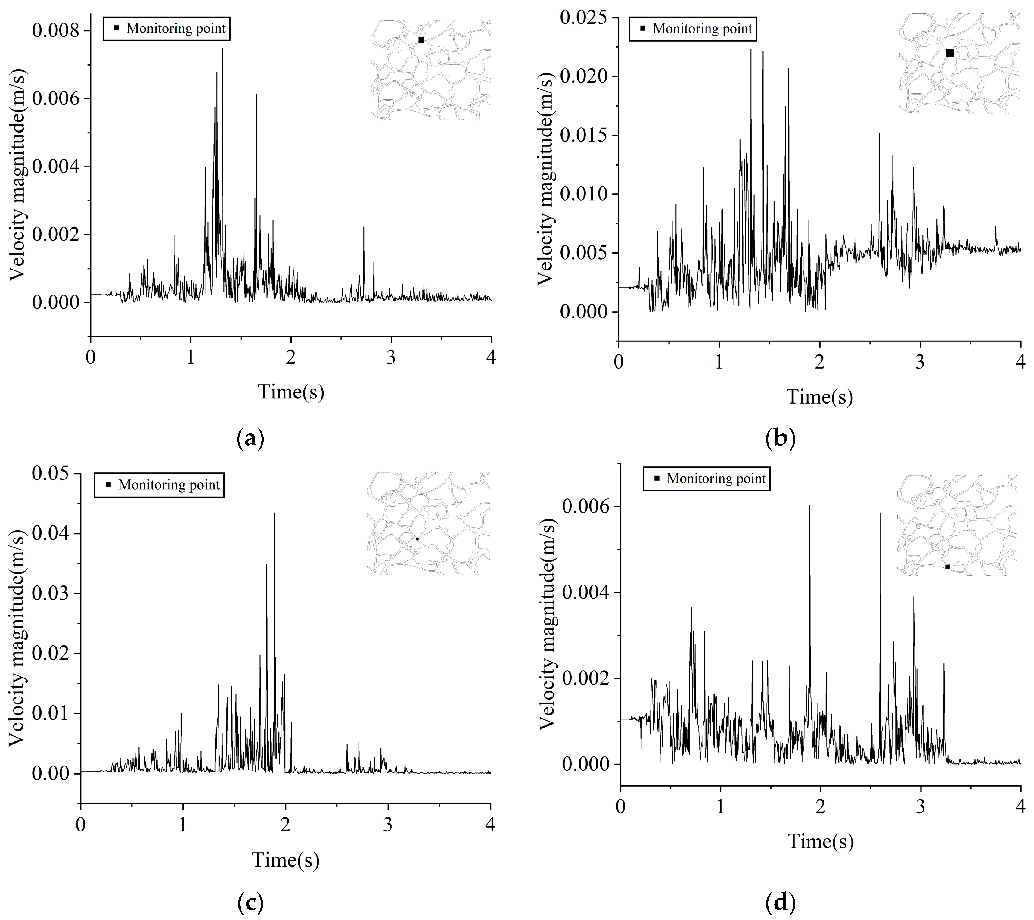
Figure 4 depicts the change in fluid velocity with time at four different points in the pore–throat model of microporous media. The fluid velocities at the monitoring points in Figure 4a,d are significantly lower than those in Figure 4b,c, indicating an uneven displacement process, different displacement capacities in different pore channels, and the existence of a main water displacement path. In Figure 4a–d, the fluid velocities at different monitoring points change abruptly and are pulse-like, but they do not change significantly after 3.5 s. This is because the capillary pressure at the interface changes as the interface shape changes with the throat section size when the liquid–liquid interface moves forward in the irregular throat channel. That is, the liquid–liquid interface expands and contracts from time to time, resulting in the interface always being in a transient unbalanced state, which causes the fluid velocity to change due to the expansion and contraction of the liquid–liquid interface. Moreover, microscopic observations of seepage in the porous media indicate that the interface always strives to reach a state of minimum energy, leading to sudden jumps in the adjustment of the meniscus shape. This observation demonstrates that fluid does not flow uniformly through porous media but rather progresses in jumps (Haynes jump) [40,41,42]. It is worth mentioning that the occurrence of Haynes jump may be closely related to the fluid velocity, pore structure, and fluid viscosity ratio. The smaller the fluid flow rate, the more homogeneous the pore structure, and the lower the fluid viscosity ratio, the lower the probability of a Haynes jump occurring and the more uniform the fluid flow becomes.

4.2. Oil–Water Dynamic Behaviors in a Steady State

4.2.1. Sweep

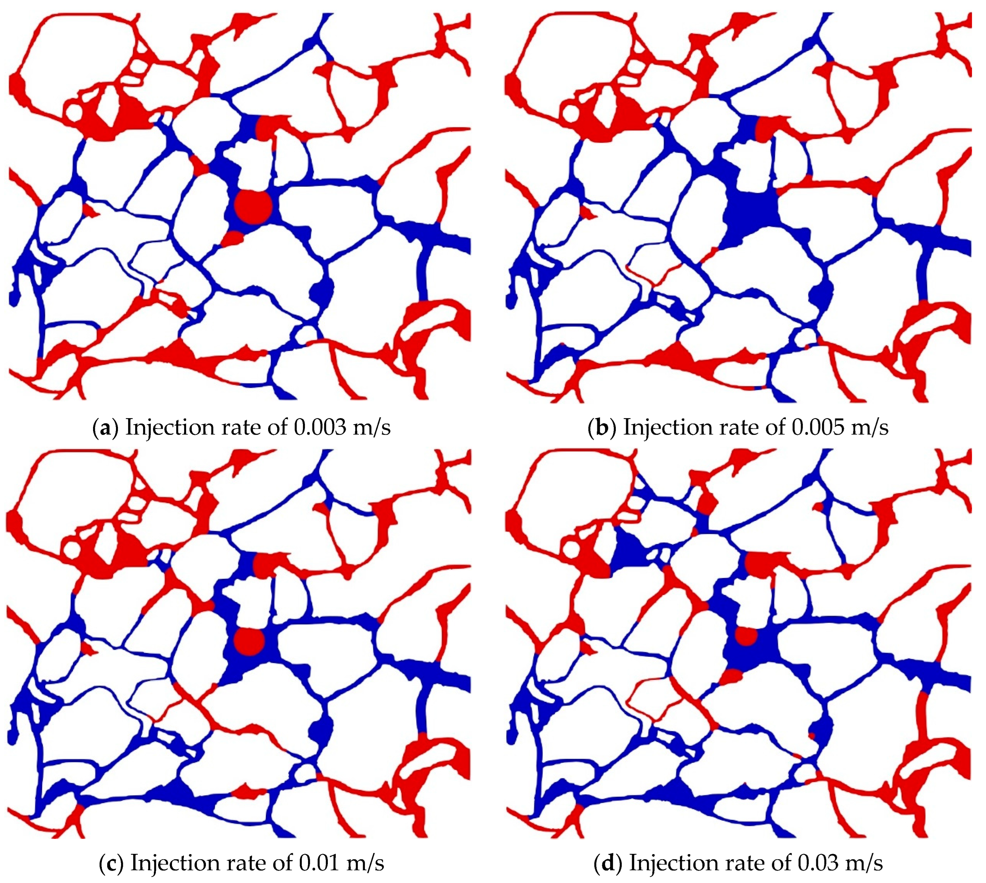
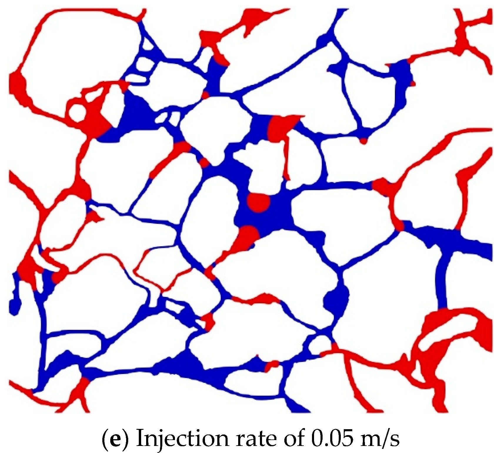
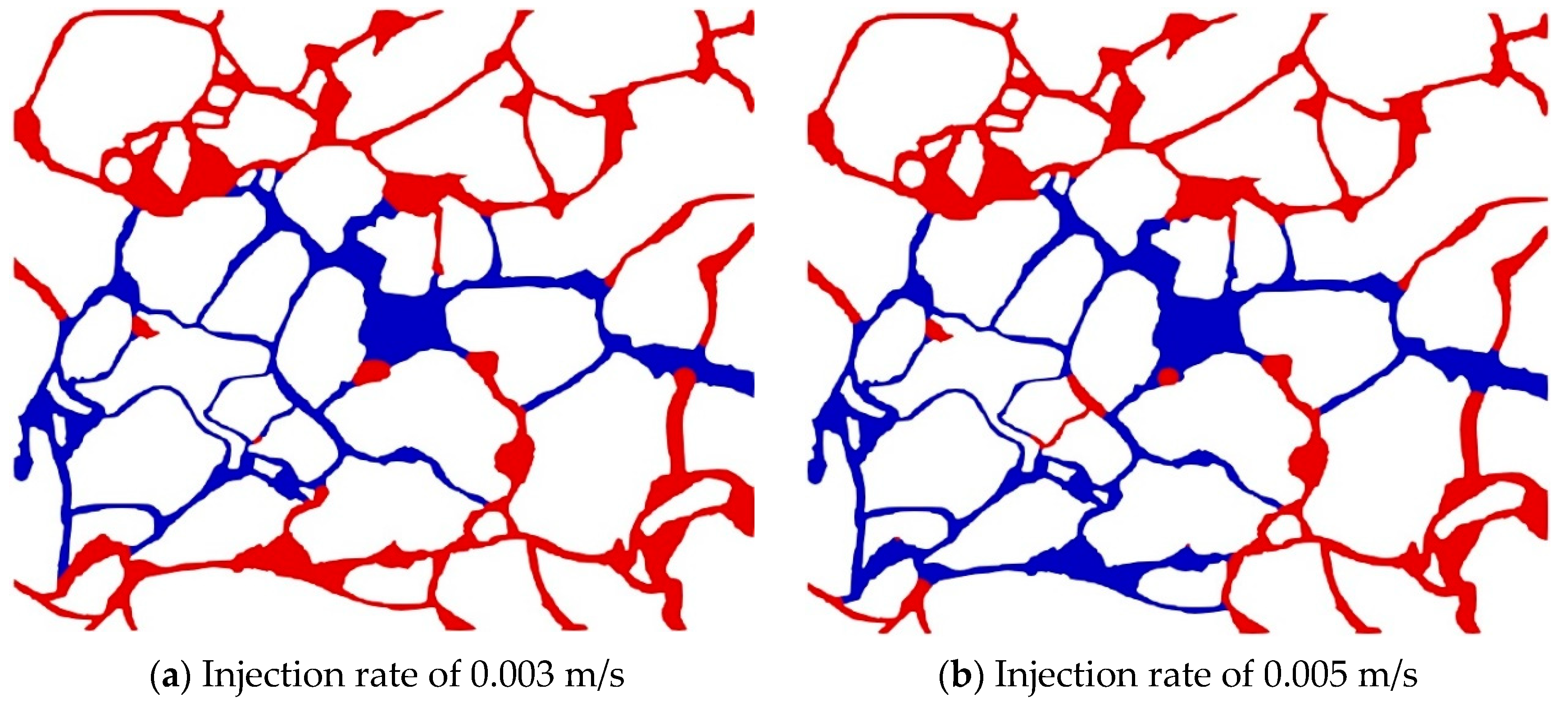
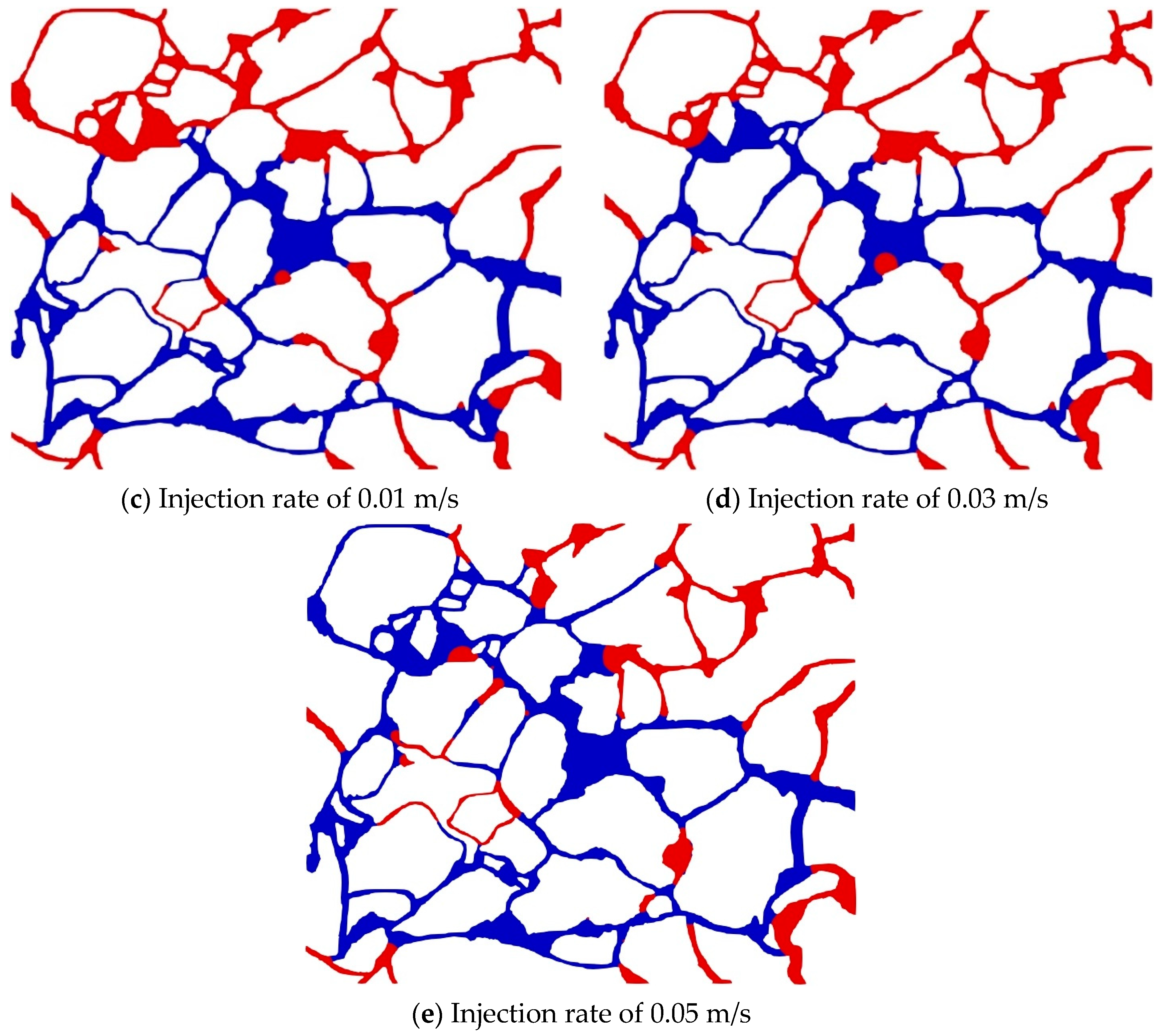
Figure 5 displays the oil–water two-phase distribution in the micro-pore model at different injection rates after stable water flow has been established from the outlet over a long period of time. Figure 5a–e illustrate that, with an increasing injection rate, the largest swept area is formed via displacement at a fluid velocity of 0.03 m/s, and the blind side oil is formed above and below the pore model. Moreover, the displacement is complete at low velocity and insignificant at high injection rates in the fine throat located in the middle of the left side of the pore model. Figure 5a,b reveal that, at injection rates of 0.003 m/s and 0.005 m/s, the viscous force is lower than the capillary force, meaning that the flow is mainly controlled by the capillary force, resulting in a capillary fingering feature and a weakened lateral sweep effect. With a continuously increasing flow rate, especially at 0.01 and 0.03 m/s, the capillary phenomenon gradually weakens, and water enters the pore channel first, followed by both the big and small pore–throats simultaneously. The front edge of the oil–water interface advances more uniformly, forming a larger swept area. Figure 5e presents the water–oil two-phase distribution at the highest injection rate. It has a slightly smaller swept area than Figure 5d because, at high injection rates, high-water-cut channels rapidly form in the main flooding direction, reducing the swept area.
The re-displacement process was conducted after reducing the interfacial tension coefficient by a factor of ten, based on the results of the water flooding simulation in the pore model at different injection rates. Figure 6 illustrates the stable oil–water two-phase distribution at an elevated injection rate. In Figure 6a–e, the swept area below the pore model is further increased at an elevated injection rate. A small amount of residual oil is produced in the area above the pore model only in Figure 6e. This is mainly due to the fact that the water and oil phases primarily distribute above and below the pore model at different injection rates, resulting in high and low average viscosities of the fluid in the upper and lower regions, respectively. Consequently, the remaining oil below the pore model is more easily displaced at an elevated injection rate and driving force. Furthermore, with an increasing reinjection rate from 0.03 m/s to 0.5 m/s, the swept area under the pore model increases, as shown in Figure 6a–e. This indicates that an increasing water driving force can generally enhance the degree of residual oil production.
The main path of displacement can be altered by adjusting the inlet/outlet position, which can affect the oil–water two-phase distribution and recovery factor. Re-displacement is carried out at a constant injection rate by changing the inlet/outlet position based on the simulation results of the water flooding in the pore model. Figure 7 shows the oil–water two-phase distribution after adjusting the position of the outlet/inlet at different injection rates. The following was found: (1) Residual oil near the new inlet/outlet, especially the previously blocked residual oil at both sides of the inlet/outlet, was produced; the higher the injection rate, the larger the swept range. (2) Before adjusting the inlet/outlet position, a high-water-cut channel formed from left to right of the pore model, so the water still moved along the formed high-water-cut channels in the middle area of the pore model during injection and production from top to bottom. (3) It is worth mentioning that the residual oil near the inlet was produced through the middle throat, leading to oil-driven water in the middle throat and eventually changing the oil–water two-phase distribution.
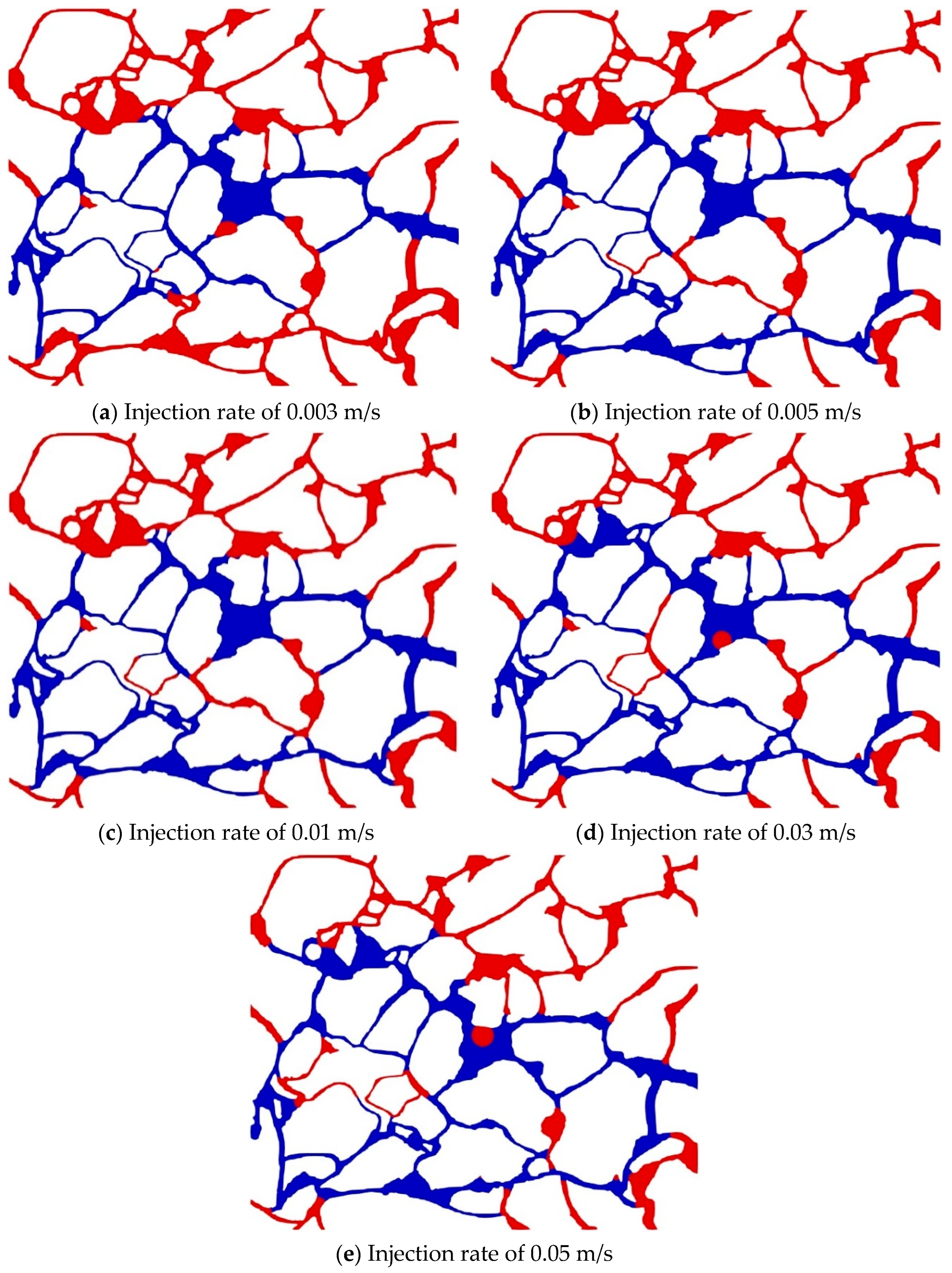
The capillary force can be directly reduced by decreasing the oil–water interface coefficient, which is conducive to further residual oil production. Figure 8 shows the re-displacement after reducing the interfacial tension coefficient by a factor of ten based on the results of the water flooding simulation in the pore model at different injection rates. In Figure 8a–d, only residual oil at the bottom of the pore channel is produced after reducing the interfacial tension. However, as the injection rate increases, the area of residual oil production at the bottom also increases significantly. Figure 8e shows that residual oil is produced above and below the entire pore structure with a large swept area at the maximum injection rate. A high injection rate generates a large driving force, and a decrease in surface tension can promote the production of more residual oil in the pore channel, especially above the pore channel. According to Equation (1), the interfacial tension of the oil and water interface decreases proportionally after reducing the interfacial tension coefficient, resulting in a decrease in the water–oil interfacial tension formed in the pores and throats. The constant water driving force can overcome this new capillary force so that residual oil can be produced. Additionally, although the water–oil interfacial tension decreases, the final oil–water interfaces at different injection rates still remain at the junctions of the pores and throats on both sides of the leading high-water-cut channels, indicating that the interfacial tension remains the primary controlling force for the movement of oil and water in the pore–throats.
After the displacement process, the oil–water two-phase flow distributes stably in the porous media, forming a high-water-cut channel from left to right. Residual oil cannot be produced at this stage due to the original oil development measures. To enhance oil recovery, various methods can be employed, such as increasing water viscosity by a factor of ten, increasing the injection rate, and reducing interfacial tension. At medium/high injection rates, as shown in Figure 9b,e, increasing the water viscosity increases the average viscosity in the whole pore model. Residual oil is produced below the pore model, forming a displacement path below the pore model due to the high driving force. The viscosity in the original water flooding channel is the same as that in the residual oil pore channel, so the flooding process is influenced only by the surface tension. Residual oil is produced when the driving force is higher than the oil–water interface tension at the junction of the pore and the throat. At a low injection rate, the driving force is small, resulting in a small absolute amount of residual oil produced. Figure 10 provides further explanation of this phenomenon.
In order to investigate the impact of viscosity on the water flooding process, a schematic diagram of water and oil dynamics in ideal throats is shown in Figure 10. When a high-water-cut channel is formed in Throat A, it becomes difficult to further produce residual oil in Throat B due to the viscosity difference between oil and water (oil-to-water viscosity ratio of 10:1), as shown in Figure 10a. At a lower oil-to-water viscosity ratio (1:1), as shown in Figure 10b, the oil–water interface in Throat B moves to the right when the driving force overcomes the interfacial tension, as the residual oil viscosity in Throats A and B is the same. This is why residual oil in Throat B can be produced. The residual oil below the pore model is displaced when the oil-to-water viscosity ratio is reduced based on the formed water flooding path in the middle of the pore model in Figure 9.

4.2.2. Recovery Factor

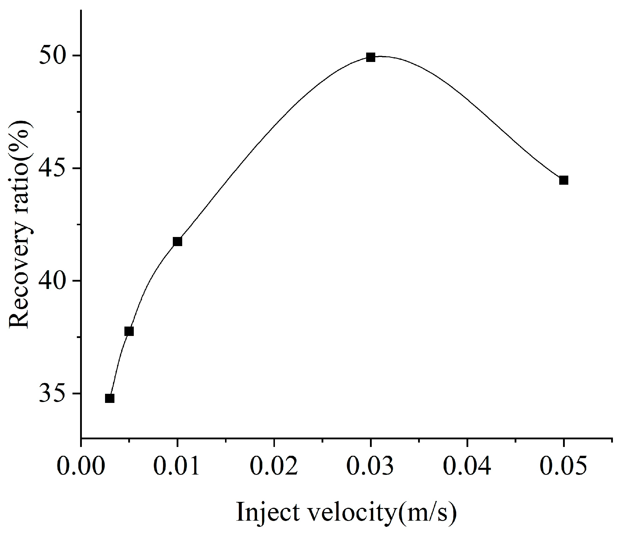
Figure 11 compares the recovery factor in the pore model at different injection rates under different adjustment measures. It shows that, with an increasing injection rate from 0.003 m/s to 0.03 m/s, the recovery factor gradually increases from 34.78% to 49.92%, and the recovery factor decreases to 44.46% at an injection rate of 0.05 m/s; i.e., there is an optimal injection rate (0.03 m/s) at a maximum recovery factor of 49.92%. This is mainly because, at low injection rates, the capillary effect dominates, and during the injection process, capillary fingering leads to lower oil recovery. At higher injection rates, the viscous effect of the fluid dominates, and viscous fingering can cause a decrease in oil recovery. At the intermediate injection rate, the viscous effect and capillary effect balance each other, promoting the smooth advancement of the oil–water interface and achieving the highest recovery factor.
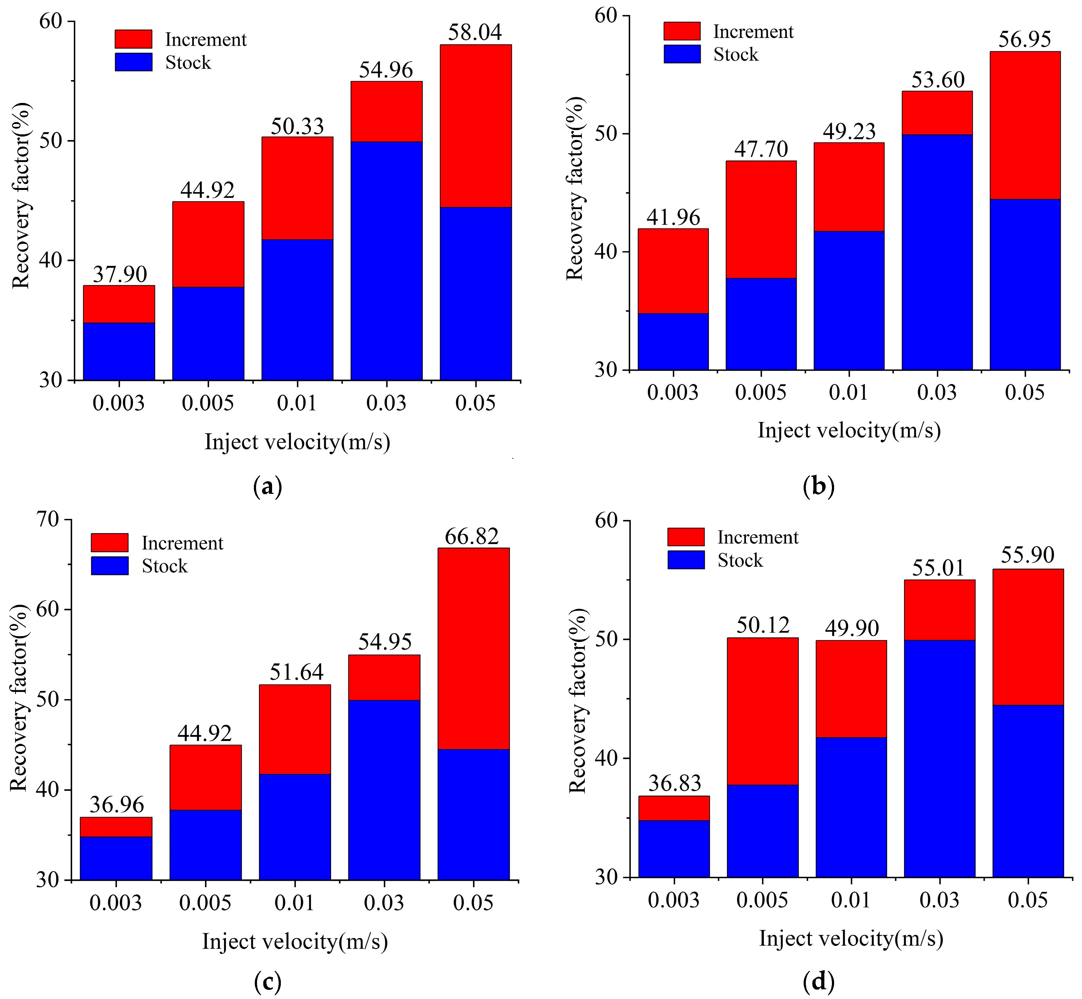
Figure 12a–d compare the total recovery factor under different measures, including increasing the injection rate, changing the inlet/outlet position, reducing the interfacial tension coefficient, increasing the water viscosity, etc. Different measures can further enhance the recovery factor to different extents. Different measures at low injection rates (0.003 m/s) increase the total recovery factor limitedly, with a maximum recovery factor of 41.96%, by only 4.06%. At a high injection rate (0.05 m/s), the maximum recovery factor of 66.82% can be obtained by reducing the interfacial tension coefficient, and different measures can achieve a higher total recovery factor. It should be noted that the absolute recovery factor was still low at a low injection rate and large at a high injection rate after adjusting the development measures; i.e., the injection rate used in the initial recovery influences the total recovery factor under the subsequent measures.
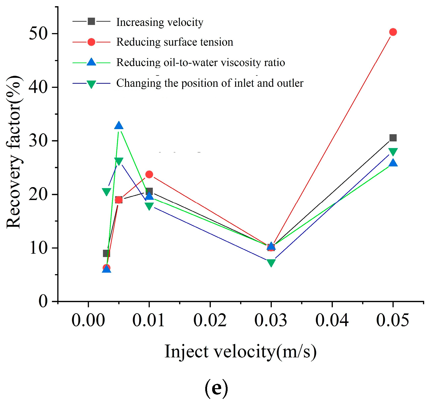
Figure 12e shows the relative enhanced recovery factor under different measures (injection rate, surface coefficient, viscosity, etc.). Although the injection rate, surface coefficient, and viscosity are increased by a factor of ten, the production of residual oil is not increased by the same factor. The recovery factor is increased relatively significantly by reducing the surface tension coefficient at a medium/high injection rate (≥0.01 m/s) and by increasing the viscosity of water at a low injection rate (<0.01 m/s).

5. Conclusions

In this paper, the VOF method was used for a numerical simulation of the oil–water two-phase dynamic behaviors of microporous media. The different development measures after water flooding were analyzed, and the influences of four measures, namely, increasing the injection rate, reducing the interfacial tension coefficient, increasing the water viscosity, changing the inlet/outlet position, on the oil–water two-phase distribution and recovery factor were investigated. The micro-mechanism was explained, and the following conclusions were drawn:
(1)
In the process of micro-pore media displacement, the forward movement of the oil–water interface in the throat and pores can lead to changes in the magnitude and direction of interfacial tension. This is the direct reason for the step migration of the oil–water interface or the change in displacement channels at different times.
(2)
A difference in the injection rate will lead to variations in the dominant effect of water flooding (the viscous effect or capillary effect) in porous media. This is also the direct reason why the recovery rate increases initially and then decreases as the injection rate increases.
(3)
Different measures can increase the swept area and recovery factor by increasing the fluid driving force in the pores, reducing the oil–water interfacial tension, changing the oil–water path, increasing the oil–water viscosity uniformity, etc. The recovery factor can be significantly relatively greatly increased by reducing the surface tension coefficient at medium and high injection rates (≥0.01 m/s) and by increasing the viscosity of water at a low injection rate (<0.01 m/s).

Author Contributions

Conceptualization, L.W. and Z.C.; methodology, H.W.; software, L.W. and Z.C.; investigation, S.D. and S.F.; data curation, H.W.; writing—original draft preparation, L.W. and Y.W.; writing—review and editing, L.W. and S.F.; visualization, S.D. and H.W. All authors have read and agreed to the published version of the manuscript.

Funding

This research was funded by the “Scientific Research Program Funded by Education Department of Shaanxi Provincial Government (Program No. 22JT036)”.

Data Availability Statement

All data are given in this paper.

Conflicts of Interest

The authors declare no conflict of interest.

References

  1. Pinilla, A.; Asuaje, M.; Ratkovich, N. Experimental and computational advances on the study of viscous fingering: An umbrella review. Heliyon 2021, 7, 07614. [Google Scholar] [CrossRef] [PubMed]
  2. Imhoff, P.T.; Miller, C.T. Dissolution fingering during the solubilization of nonaqueous phase liquids in saturated porous media: 2. experimental observations. Water Resour. Res. 1996, 32, 1919–1928. [Google Scholar] [CrossRef]
  3. Rodriguez, D.; Goyeau, B. Numerical analysis of the pore-scale mechanisms controlling the efficiency of immiscible displacement of a pollutant phase by a shear-thinning fluid. Chem. Eng. Sci. 2022, 251, 117462. [Google Scholar] [CrossRef]
  4. Saraf, S.; Bera, A. A review on pore-scale modeling and CT scan technique to characterize the trapped carbon dioxide in impermeable reservoir rocks during sequestration. Renew. Sustain. Energy Rev. 2021, 144, 110986. [Google Scholar] [CrossRef]
  5. Yang, Y.; Cai, S.; Yao, J.; Zhong, J.; Zhang, K.; Song, W.; Zhang, L.; Sun, H.; Lisitsa, V. Pore-scale simulation of remaining oil distribution in 3D porous media affected by wettability and capillarity based on volume of fluid method. Int. J. Multiph. Flow 2021, 143, 103746. [Google Scholar] [CrossRef]
  6. Zakirov, T.R.; Khramchenkov, M.G. Pore-scale study of the anisotropic effect on immiscible displacement in porous media under different wetting conditions and capillary numbers. J. Pet. Sci. Eng. 2022, 208, 109484. [Google Scholar] [CrossRef]
  7. Zakirov, T.R.; Khramchenkov, M.G. Wettability effect on the invasion patterns during immiscible displacement in heterogeneous porous media under dynamic conditions: A numerical study. J. Pet. Sci. Eng. 2021, 206, 109049. [Google Scholar] [CrossRef]
  8. Maksim, L.; Geir, E.; Martin, F. Pore-scale dynamics for underground porous media hydrogen storage. Adv. Water Resour. 2022, 163, 104167. [Google Scholar]
  9. Wang, J.L.; Yang, Y.F.; Cai, S.B.; Yao, J.; Xie, Q. Pore-scale modelling on hydrogen transport in porous media: Implications for hydrogen storage in saline aquifers. Int. J. Hydrogen Energy 2023, 48, 13922–13933. [Google Scholar] [CrossRef]
  10. Ma, K.; Liontas, R.; Conn, C.A.; Hirasaki, G.J.; Biswal, S.L. Visualization of improved sweep with foam in heterogeneous porous media using microfluidics. Soft Matter 2012, 8, 10669–10675. [Google Scholar] [CrossRef]
  11. Mahdi, M.B.; Cyprien, S.; Mohamed, A.; Sophie, R. How interfacial dynamics controls drainage pore-invasion patterns in porous media. Adv. Water Resour. 2023, 171, 104353. [Google Scholar]
  12. Hu, Y.; Patmonoaji, A.; Zhang, C.; Suekane, T. Experimental study on the displacement patterns and the phase diagram of immiscible fluid displacement in three-dimensional porous media. Adv. Water Resour. 2020, 140, 103584. [Google Scholar] [CrossRef]
  13. Iyi, D.; Balogun, Y.; Oyeneyin, B.; Faisal, N. Numerical Modelling of the effect of wettability, interfacial tension and temperature on oil recovery at pore-scale level. J. Pet. Sci. Eng. 2021, 201, 108453. [Google Scholar] [CrossRef]
  14. Michels, R.; Siebert, D.N.; Santos, L. Investigation on the influence of capillary number on drainage in porous media using a lattice Boltzmann method. J. Pet. Sci. Eng. 2021, 205, 108918. [Google Scholar] [CrossRef]
  15. Lenormand, R.; Touboul, E.; Zarcone, C. Numerical models and experiments on immiscible displacements in porous media. J. Fluid Mech. 1988, 189, 165–187. [Google Scholar] [CrossRef]
  16. Patel, H.V.; Kuipers, J.; Peters, E. Effect of flow and fluid properties on the mobility of multiphase flows through porous media. Chem. Eng. Sci. 2019, 193, 243–254. [Google Scholar] [CrossRef]
  17. Tang, M.; Lu, S.F.; Zhan, H.B.; Guo, W.Q.; Ma, H.F. The effect of a microscale fracture on dynamic capillary pressure of two-phase flow in porous media. Adv. Water Resour. 2018, 113, 272–284. [Google Scholar] [CrossRef]
  18. Zhang, L.; Zhang, C.; Zhang, K.; Zhang, L.; Yao, J.; Sun, H.; Yang, Y. Pore-scale investigation of methane hydrate dissociation using the Lattice Boltzmann method. Water Resour. Res. 2019, 55, 8422–8444. [Google Scholar] [CrossRef]
  19. Zhao, J.; Yao, J.; Li, A.; Zhang, M.; Zhang, L.; Yang, Y.; Sun, H. Simulation of microscale gas flow in heterogeneous porous media based on the lattice Boltzmann method. J. Appl. Phys. 2016, 120, 084306. [Google Scholar] [CrossRef]
  20. Song, W.; Yao, J.; Ma, J.; Sun, H.; Li, Y.; Yang, Y.; Hai, S.; Yang, L.; Yang, Y.F.; Zhang, L. Numerical simulation of multiphase flow in nanoporous organic matter with application to coal and gas shale systems. Water Resour. Res. 2018, 54, 1077–1092. [Google Scholar] [CrossRef]
  21. Yang, Y.; Wang, K.; Zhang, L.; Sun, H.; Zhang, K.; Ma, J. Pore-scale simulation of shale oil flow based on pore network model. Fuel 2019, 251, 683–692. [Google Scholar] [CrossRef]
  22. Yang, Q.; Yao, J.; Huang, Z.; Zhu, G.; Liu, L.; Song, W. Pore-scale investigation of petro-physical fluid behaviours based on multiphase SPH method. J. Pet. Sci. Eng. 2020, 192, 107238. [Google Scholar] [CrossRef]
  23. Zhang, L.; Xu, C.; Guo, Y.; Zhu, G.; Cai, S.; Wang, X.; Jing, W.; Sun, H.; Yang, Y.; Yao, J. The effect of surface roughness on immiscible displacement using pore scale simulation. Transp. Porous Media 2021, 140, 713–725. [Google Scholar] [CrossRef]
  24. Peng, J.; Song, R.; Wang, Y.; Xiao, H. Comparative study of VOF, LS, and VOSET on pore-scale immiscible waterflooding modeling. Petroleum 2021, 7, 314–324. (In Chinese) [Google Scholar] [CrossRef]
  25. Ferrari, A.; Magnini, M.; Thome, J.R. A flexible coupled level set and volume of fluid (flexCLV) method to simulate microscale two-phase flow in non-uniform and unstructured meshes. Int. J. Multiph. Flow 2017, 91, 276–295. [Google Scholar] [CrossRef]
  26. de Castro, A.R.; Agnaou, M.; Gostick, J. Predicting shear-thinning fluid flows in porous media using pore network modeling: Simulations and experimental validation. Transp. Porous Media 2023. [Google Scholar] [CrossRef]
  27. Yu, H.S.; Leung, J.Y. Numerical pore-scale simulation of propane injection for heavy oil displacement processes. Int. J. Multiph. Flow 2023, 159, 104319. [Google Scholar] [CrossRef]
  28. Liu, H.; Valocchi, A.J.; Werth, C.; Kang, Q.; Oostrom, M. Pore-scale simulation of liquid CO2 displacement of water using a two-phase lattice Boltzmann model. Adv. Water Resour. 2014, 73, 144–158. [Google Scholar] [CrossRef] [Green Version]
  29. Liu, H.; Zhang, Y.; Valocchi, A.J. Lattice Boltzmann simulation of immiscible fluid displacement in porous media: Homogeneous versus heterogeneous pore network. Phys. Fluids 2015, 27, 052103. [Google Scholar] [CrossRef] [Green Version]
  30. Liu, H.; Valocchi, A.J.; Kang, Q.; Werth, C. Pore-scale simulations of gas displacing liquid in a homogeneous pore network using the lattice Boltzmann method. Transp. Porous Media 2013, 99, 555–580. [Google Scholar] [CrossRef]
  31. Hirt, C.W.; Nichols, B.D. Volume of fluid (VOF) method for the dynamics of free boundaries. J. Comput. Phys. 1981, 39, 201–225. [Google Scholar] [CrossRef]
  32. Yu, D.; Tang, L.; Chen, C. Three-dimensional numerical simulation of mud flow from a tailing dam failure across complex terrain. Nat. Hazards Earth Sys. Sci. 2020, 20, 727–741. [Google Scholar] [CrossRef] [Green Version]
  33. Hu, R.; Wan, J.M.; Kim, Y.K.; Tokunaga, T.K. Wettability effects on supercritical CO2–brine immiscible displacement during drainage: Pore-scale observation and 3D simulation. Int. J. Greenh. Gas Control 2017, 60, 129–139. [Google Scholar] [CrossRef] [Green Version]
  34. Sarris, E.; Gravanis, E. Flow regime analysis of the pressure build-up during CO2 injection in saturated porous rock formations. Energies 2019, 12, 2972. [Google Scholar] [CrossRef] [Green Version]
  35. Booshi, S.; Ketabdari, M.J. Modeling of solitary wave interaction with emerged porous breakwater using PLIC-VOF method. Ocean Eng. 2021, 241, 110041. [Google Scholar] [CrossRef]
  36. Feichtner, A.; Mackay, E.; Tabor, G.; Thies, P.R.; Johanning, L. Comparison of macro-scale porosity implementations for CFD modelling of wave interaction with thin porous structures. J. Mar. Sci. Eng. 2021, 9, 150. [Google Scholar] [CrossRef]
  37. Minakov, A.V.; Guzei, D.V.; Pryazhnikov, M.I.; Filimonov, S.A.; Voronenkova, Y.O. 3D pore-scale modeling of nanofluids-enhanced oil recovery. Pet. Explor. Dev. 2021, 48, 956–967. [Google Scholar] [CrossRef]
  38. O’Brien, A.; Afkhami, S.; Bussmann, M. Pore-scale direct numerical simulation of Haines jumps in a porous media model. Eur. Phys. J. Spec. Top 2020, 229, 1785–1798. [Google Scholar] [CrossRef]
  39. Ambekar, A.S.; Mattey, P.; Buwa, V.V. Pore-resolved two-phase flow in a pseudo-3D porous medium: Measurements and volume-of-fluid simulations. Chem. Eng. Sci. 2021, 230, 116128. [Google Scholar] [CrossRef]
  40. Armstrong, R.T.; Evseev, N.; Koroteev, D.; Berg, S. Modeling the velocity field during Haines jumps in porous media. Adv. Water Resour. 2015, 77, 57–68. [Google Scholar] [CrossRef] [Green Version]
  41. Zacharoudiou, I.; Boek, E.S. Capillary filling and Haines jump dynamics using free energy Lattice Boltzmann simulations. Adv. Water Resour. 2016, 92, 43–56. [Google Scholar] [CrossRef] [Green Version]
  42. Timur, R.Z.; Maxim, G.K. Characterization of two-phase displacement mechanisms in porous media by capillary and viscous forces estimation using the lattice Boltzmann simulations. J. Pet. Sci. Eng. 2020, 184, 106575. [Google Scholar]
Figure 1. Physical model of the microporous media.
Energies 16 05047 g001
Figure 2. Oil–water two-phase distribution in the pores at injection rate of 0.003 m/s at different times. (a) 0.58 s. (b) 0.685 s. (c) 0.795 s. (d) 0.9 s. (e) 1.085 s. (f) 1.22 s.
Energies 16 05047 g002
Figure 3. Conceptual model of oil–water interface movement in pores and throats. (a) step 1. (b) step 2. (c) step 3. The red line in the figure represents the position of the oil-water interface.
Energies 16 05047 g003
Figure 4. Change in fluid velocity with time at the monitoring points. (a) point 1. (b) point 2. (c) point 3. (d) point 4.
Energies 16 05047 g004
Figure 5. Oil–water two-phase distribution in the pores at different injection rates.
Energies 16 05047 g005
Figure 6. Oil–water two-phase distribution of fluid in pores after increasing different velocities.
Energies 16 05047 g006
Figure 7. Oil–water two-phase distribution in the pores after changing the positions of inlet and outlet.
Energies 16 05047 g007aEnergies 16 05047 g007b
Figure 8. Oil–water two-phase distribution in the pores after reducing surface tension (0.007 kg/m−2).
Energies 16 05047 g008aEnergies 16 05047 g008b
Figure 9. Oil–water two-phase distribution in the pores after reducing oil-to-water viscosity ratio (1:1).
Energies 16 05047 g009
Figure 10. Schematic diagram of oil–water two-phase distribution at lower viscosity.
Energies 16 05047 g010
Figure 11. Change in recovery factor at different injection rates.
Energies 16 05047 g011
Figure 12. Comparison of recovery factor. (a) Comparison of recovery factor after increasing different velocities. (b) Comparison of recovery factor after changing the position of inlet and outlet. (c) Comparison of recovery factor after reducing surface tension. (d) Comparison of recovery factor after reducing oil-to-water viscosity ratio. (e) Change in relative recovery factor at different factors.
Energies 16 05047 g012aEnergies 16 05047 g012b
Table 1. Velocity at the monitoring points with different numbers of elements.
Element NumberPoint 1 Velocity
(0.00057, 0.00199)
Point 2 Velocity
(0.00207, 0.00164)
Point 3 Velocity
(0.00324, 0.00157)
572330.089 m/s0.0135 m/s0.0367 m/s
1051180.091 m/s0.0152 m/s0.0495 m/s
2034220.091 m/s0.0152 m/s0.0494 m/s
Table 2. Boundary condition settings.
Physical BoundaryPhysical QuantityNumerical Boundary
InletVelocityfixedValue
PressurezeroGradient
AlphafixedValue
OutletVelocityzeroGradient
PressurefixedValue
AlphazeroGradient
WallsVelocityfixedValue
PressurefixedFluxPressure
AlphaalphaContantAngle
Table 3. Parameter settings of the investigated cases.
No.Injection Rate (m/s)Increase Injection Rate (m/s)Changing the Inlet/Outlet PositionDecrease Interfacial Tension Coefficient (kg/m−2)Decrease the Viscosity Ratio of Oil to WaterCa
10.003NoNoNo change (0.07)No change (10:1)4.2 × 10⁻⁵
20.005NoNoNo change (0.07)No change (10:1)7.1 × 10⁻⁵
30.01NoNoNo change (0.07)No change (10:1)1.4 × 10⁻⁴
40.03NoNoNo change (0.07)No change (10:1)4.2 × 10⁻⁴
50.05NoNoNo change (0.07)No change (10:1)7.1 × 10⁻⁴
60.0030.03NoNo change (0.07)No change (10:1)4.2 × 10⁻⁴
70.0050.05NoNo change (0.07)No change (10:1)7.1 × 10⁻⁴
80.010.1NoNo change (0.07)No change (10:1)1.4 × 10⁻³
90.030.3NoNo change (0.07)No change (10:1)4.2 × 10⁻³
100.050.5NoNo change (0.07)No change (10:1)7.1 × 10⁻³
110.003NoYesNo change (0.07)No change (10:1)4.2 × 10⁻⁵
120.005NoYesNo change (0.07)No change (10:1)7.1 × 10⁻⁵
130.01NoYesNo change (0.07)No change (10:1)1.4 × 10⁻⁴
140.03NoYesNo change (0.07)No change (10:1)4.2 × 10⁻⁴
150.05NoYesNo change (0.07)No change (10:1)7.1 × 10⁻⁴
160.003NoNo0.007No change (10:1)4.2 × 10⁻⁴
170.005NoNo0.007No change (10:1)7.1 × 10⁻⁴
180.01NoNo0.007No change (10:1)1.4 × 10⁻³
190.03NoNo0.007No change (10:1)4.2 × 10⁻³
200.05NoNo0.007No change (10:1)7.1 × 10⁻³
210.003NoNoNo change (0.07)1:14.2 × 10⁻⁵
220.005NoNoNo change (0.07)1:17.1 × 10⁻⁵
230.01NoNoNo change (0.07)1:11.4 × 10⁻⁴
240.03NoNoNo change (0.07)1:14.2 × 10⁻⁴
250.05NoNoNo change (0.07)1:17.1 × 10⁻⁴
Disclaimer/Publisher’s Note: The statements, opinions and data contained in all publications are solely those of the individual author(s) and contributor(s) and not of MDPI and/or the editor(s). MDPI and/or the editor(s) disclaim responsibility for any injury to people or property resulting from any ideas, methods, instructions or products referred to in the content.