
A Novel Energy Balance Control Method for a Modular Multilevel Converter in a High-Speed PMSM Drive Application


Abstract
:1. Introduction
2. Basic Principles of the MMC and Energy Model Analysis
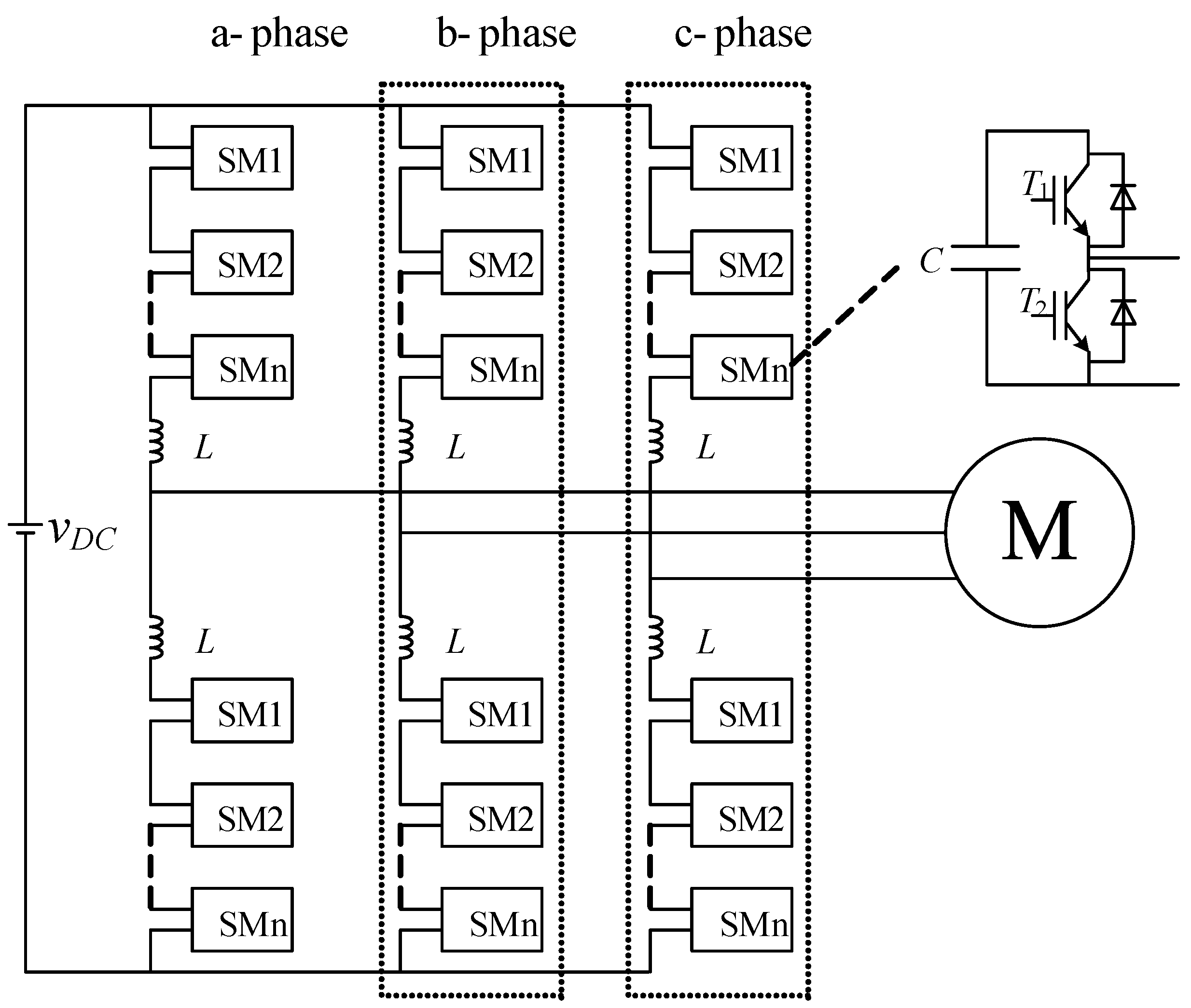
2.1. MMC Topology
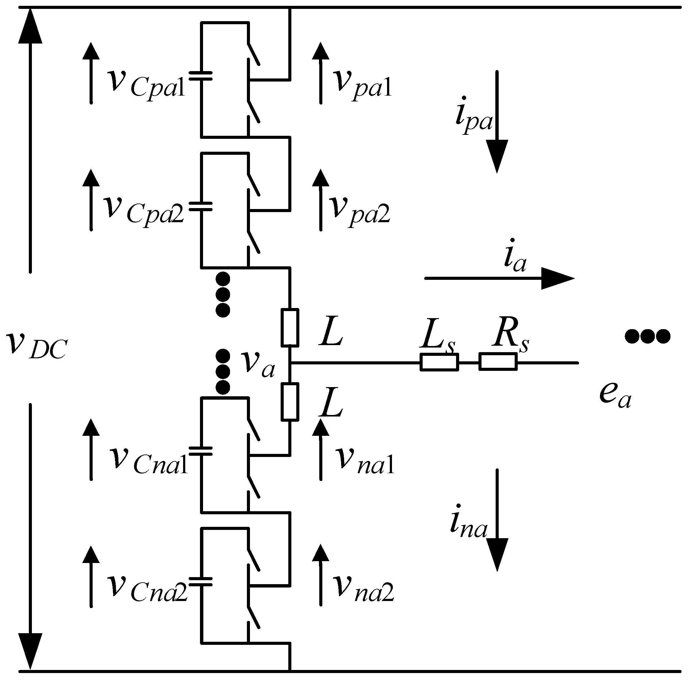
2.2. Circuit Architecture
2.3. Submodule Capacitor Energy Model
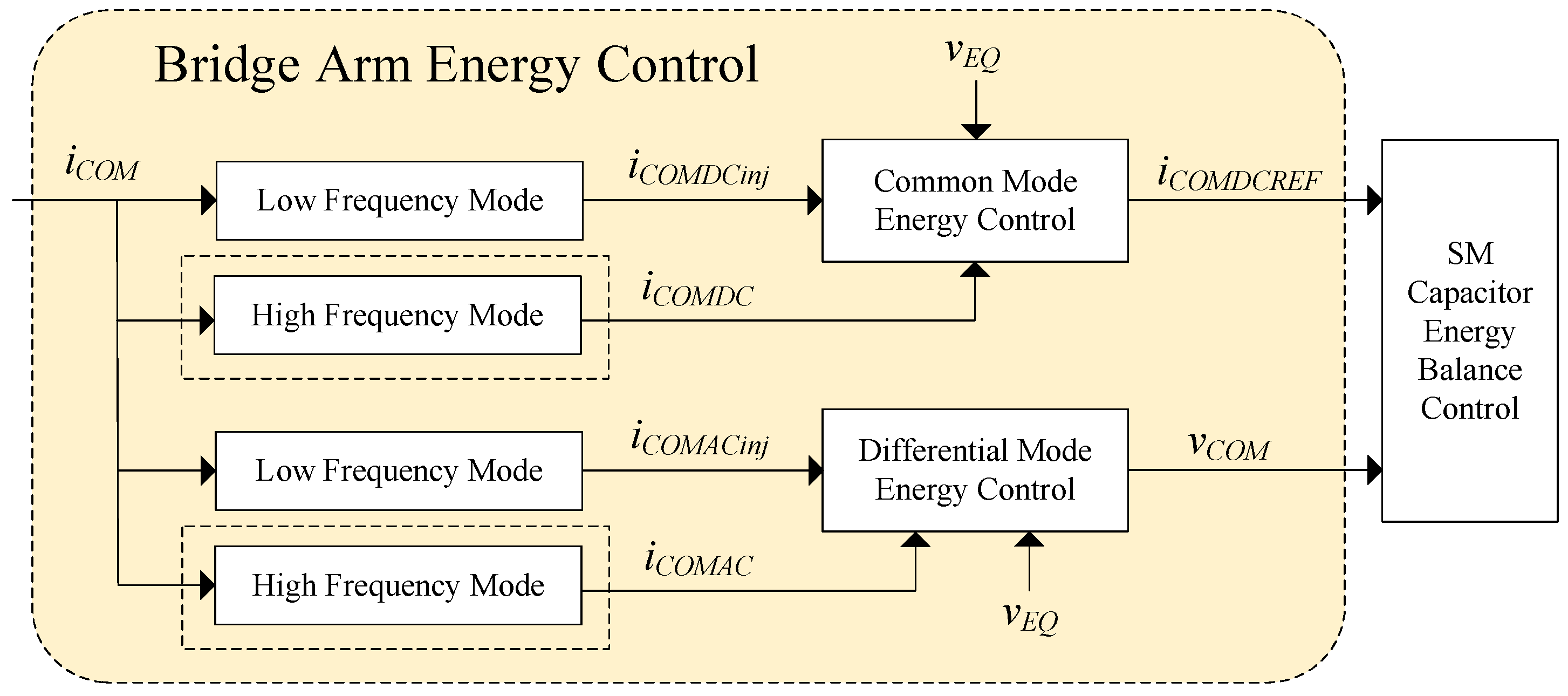
2.4. Bridge Arm Energy Balance Control Scheme
2.4.1. High-Frequency Mode
2.4.2. Low-Frequency Mode
3. Energy Balance Controller Design
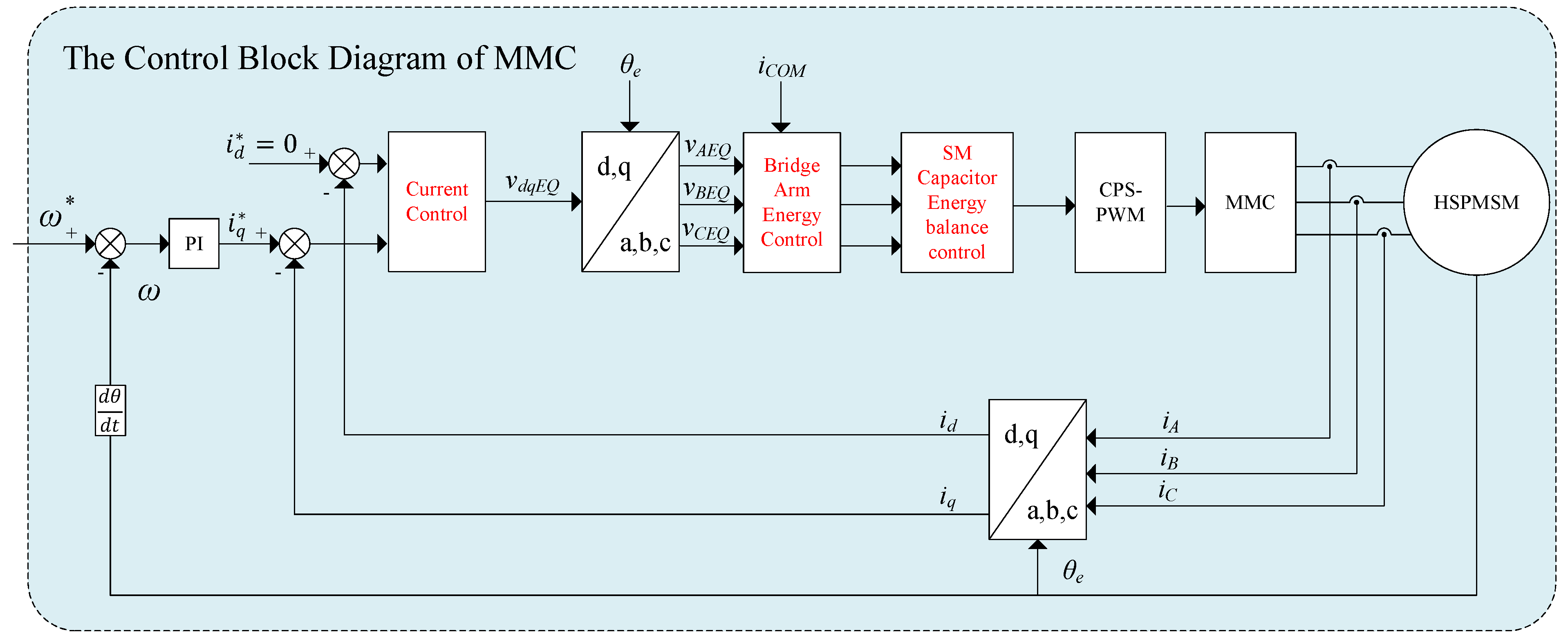
3.1. Bridge Arm Energy Balance and Current Control
3.1.1. Common Mode Energy Control
3.1.2. Differential Mode Energy Control
- High frequency.
- Low frequency.
3.1.3. Current Control
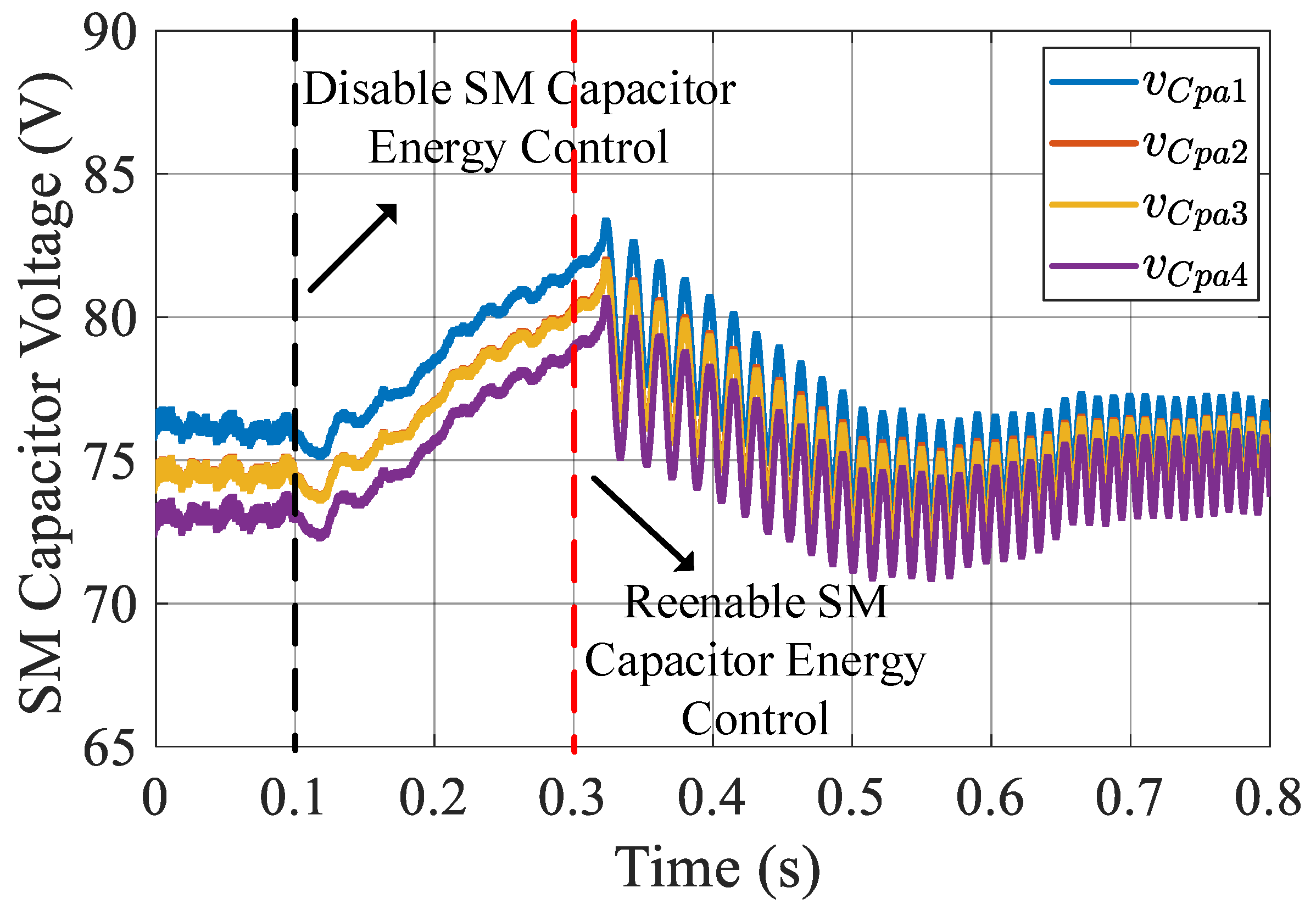
3.2. SM Capacitor Energy Balance Control
4. Validation and Analysis
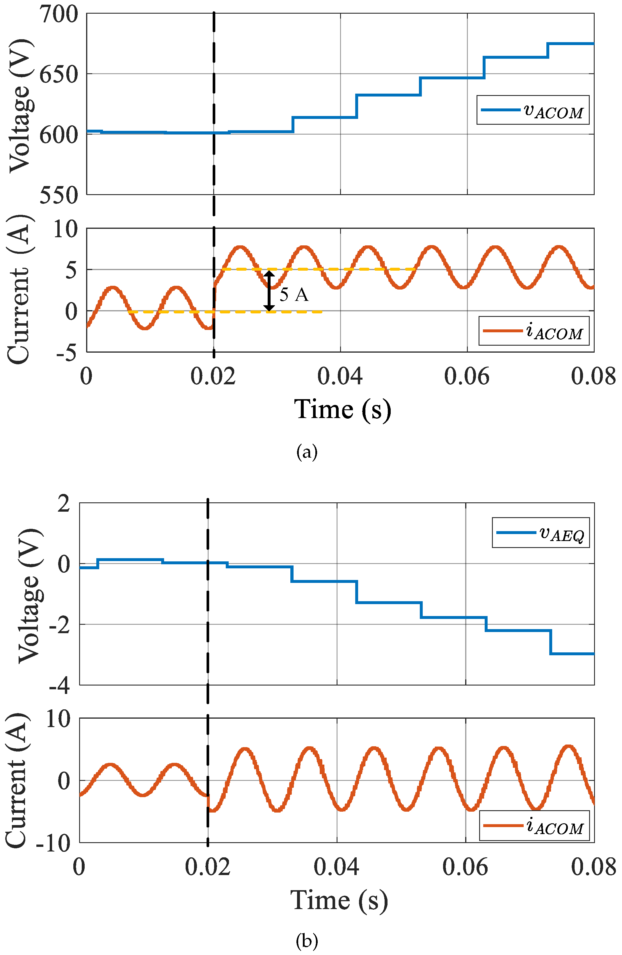
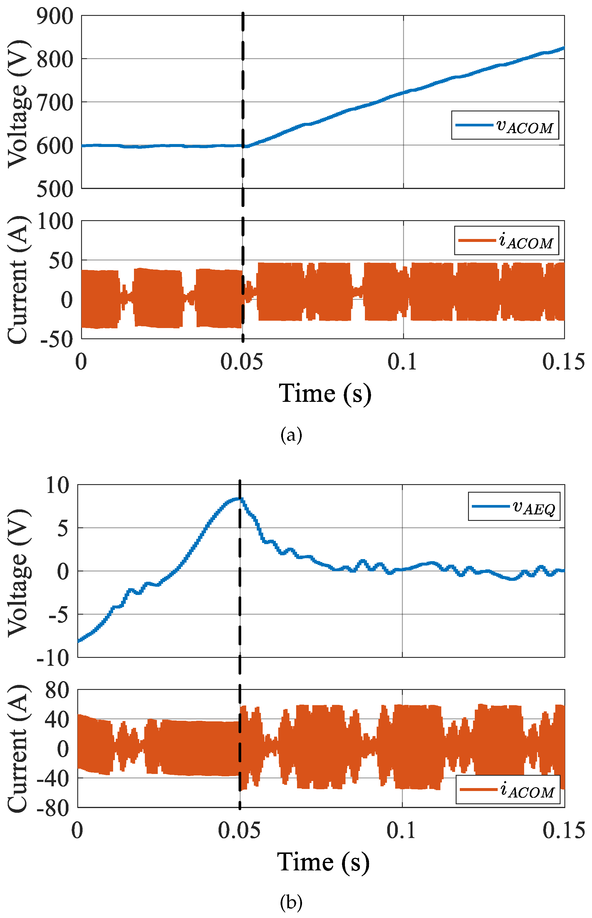
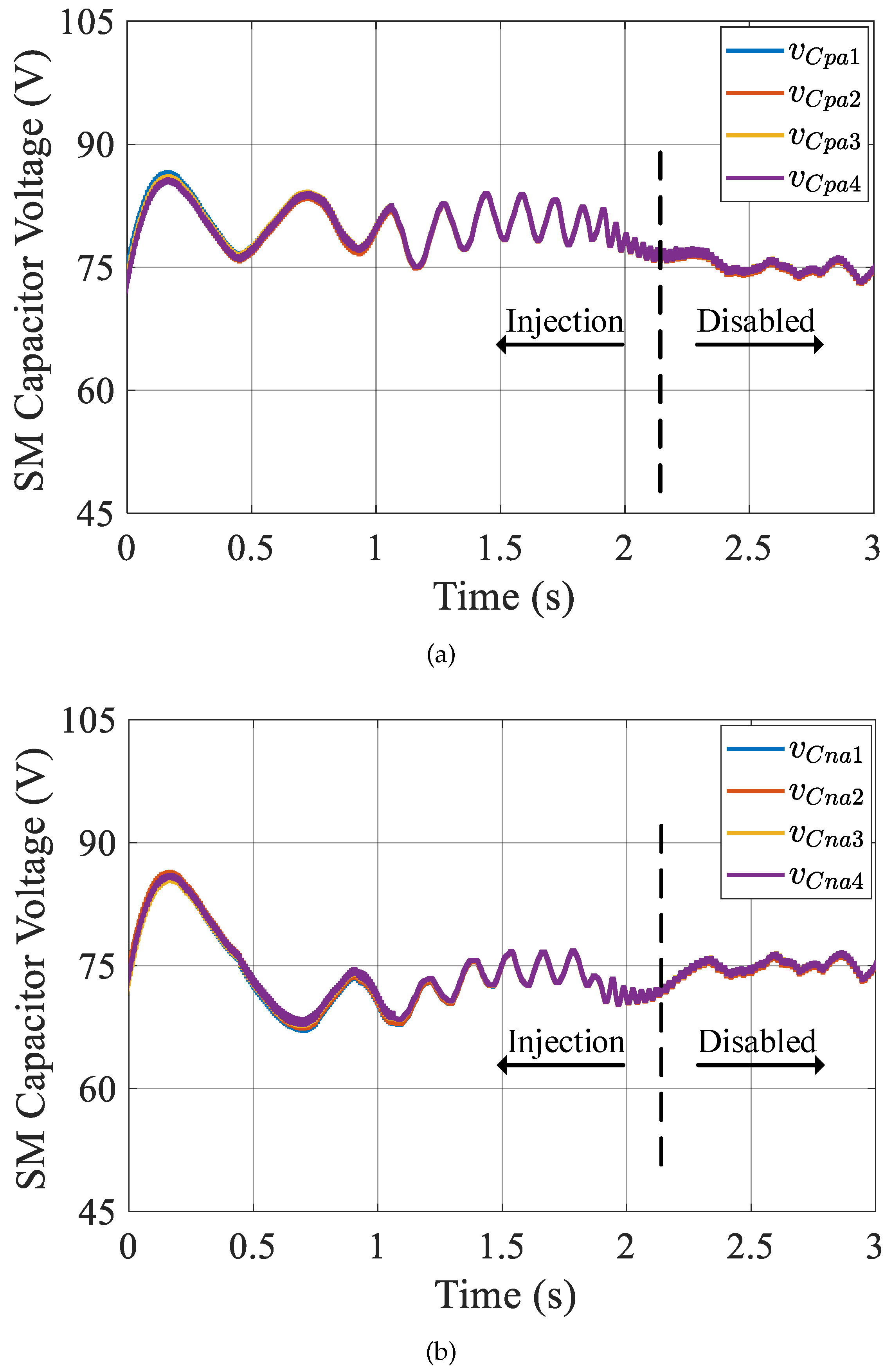
4.1. SM Capacitor Voltage Balance Performance
- Simulation results.
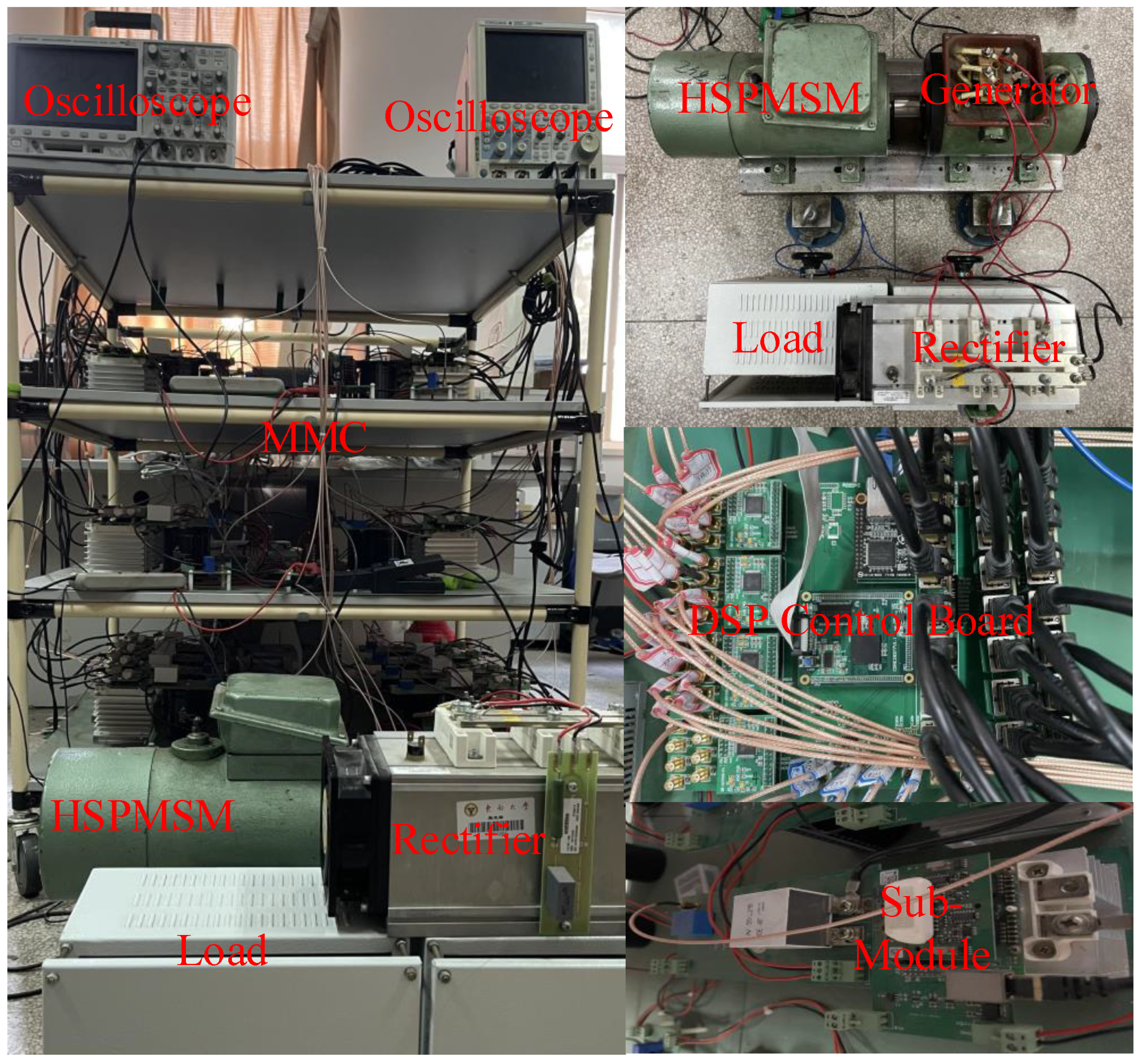
- Experimental results.
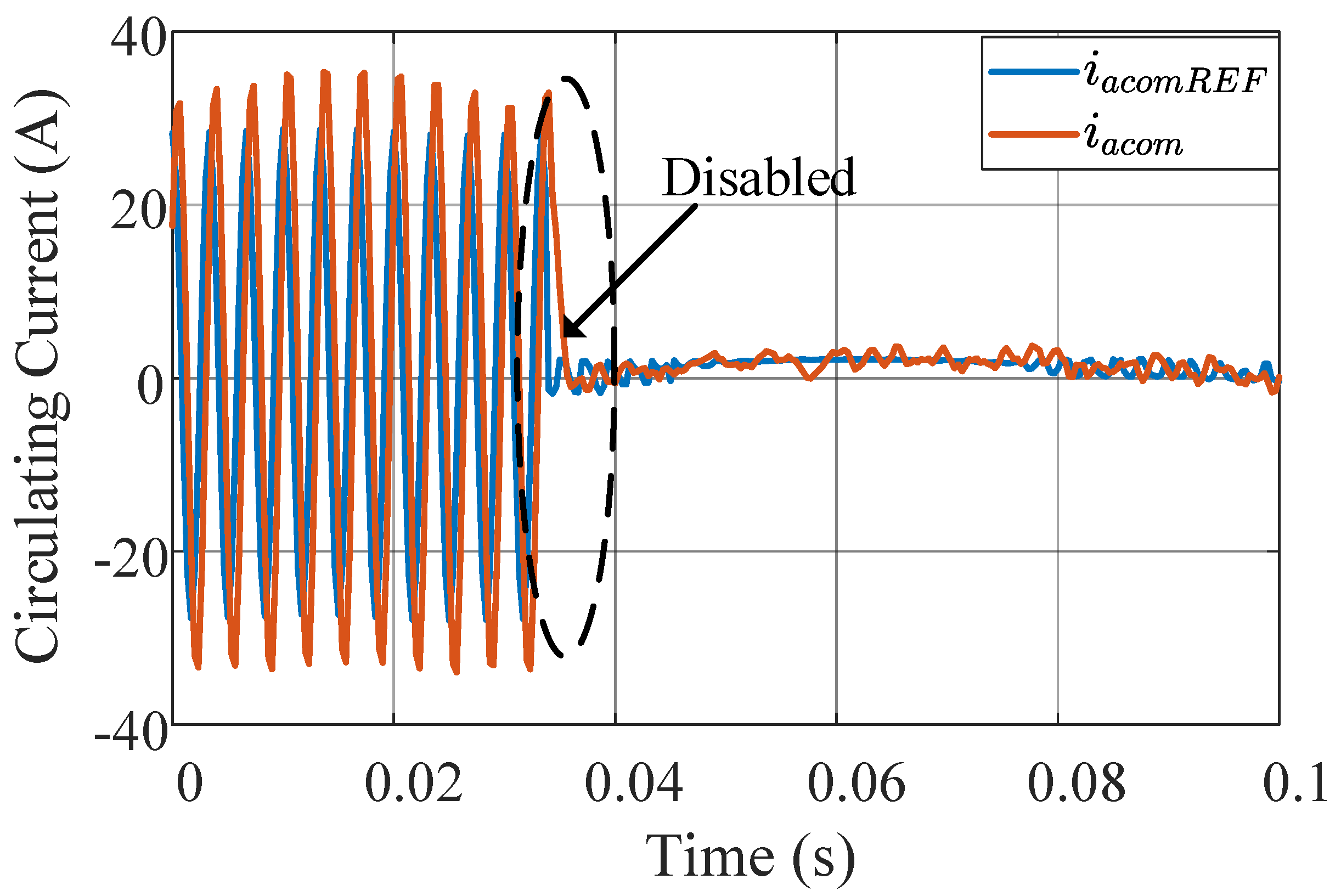
4.2. Circulating Current Performance
- Simulation results.
- Experimental results.
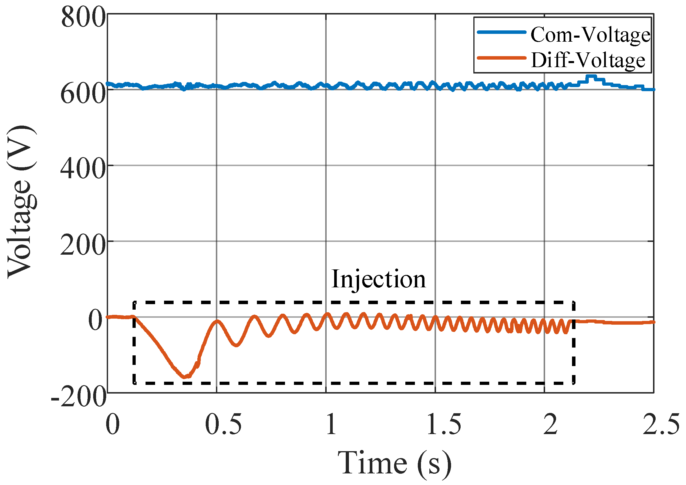
4.3. Common Mode Voltage and Differential Mode Voltage of the MMC Performance
- Experimental results.
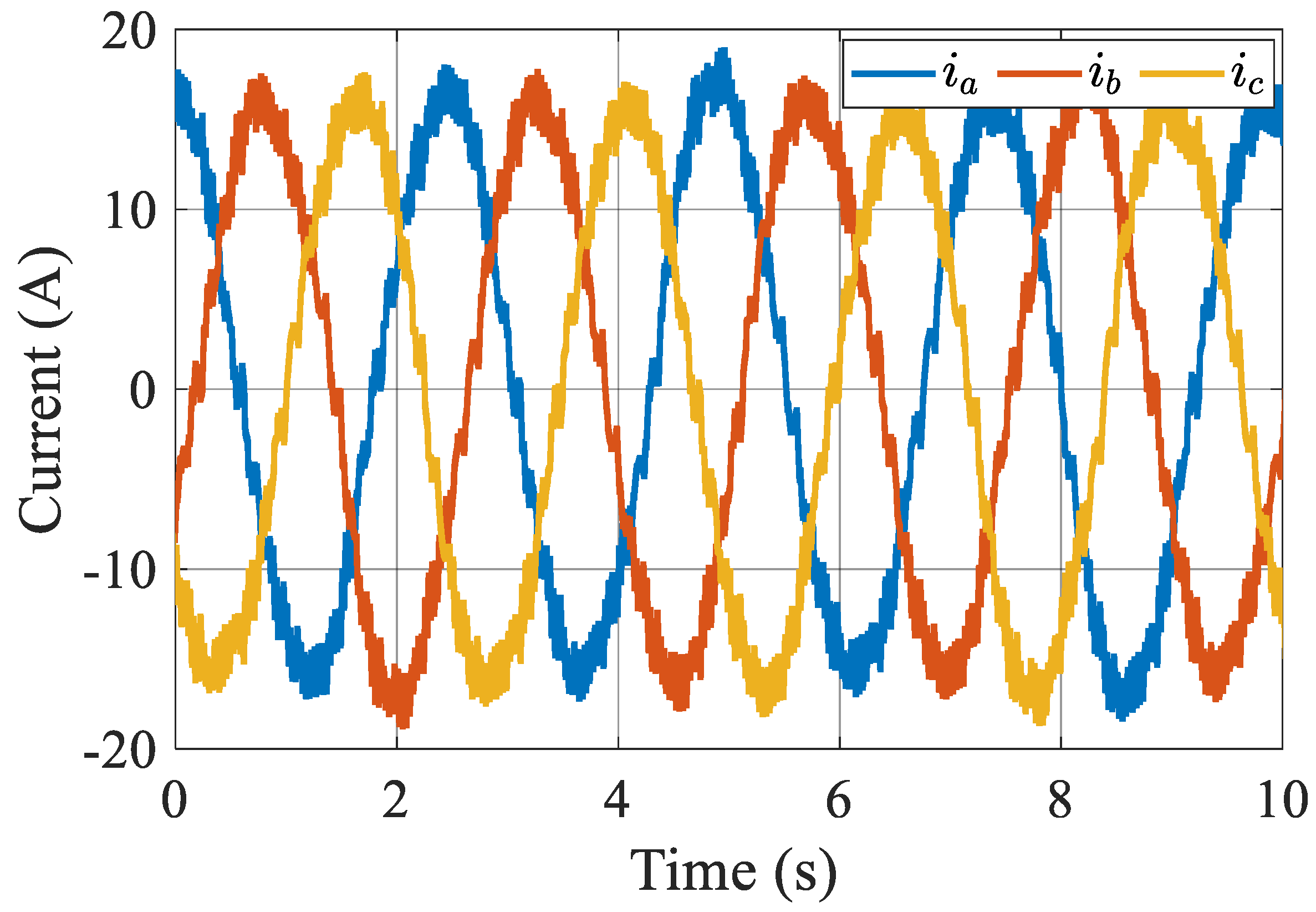
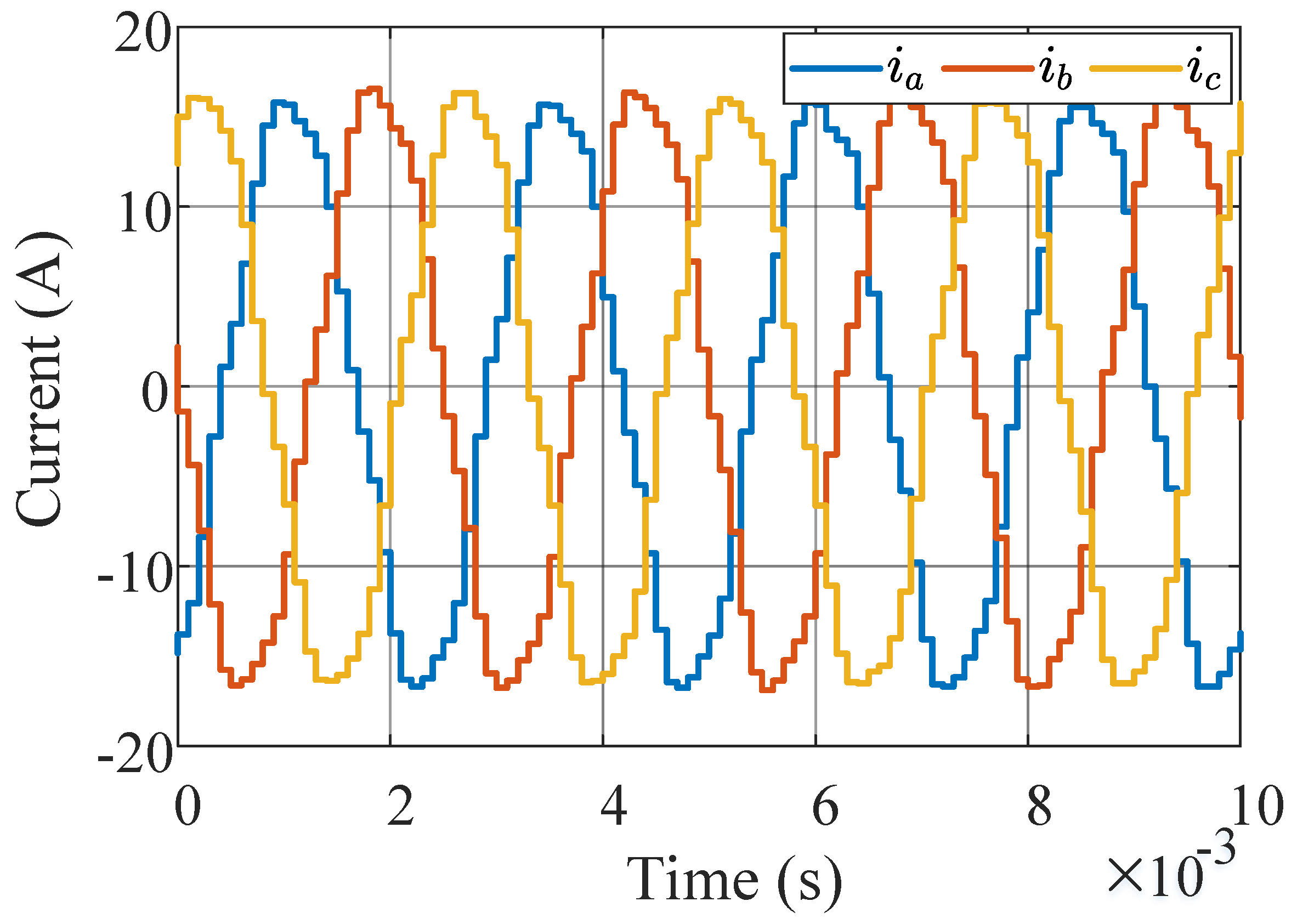
4.4. Output Current of the MMC Performance
- Simulation results.
- Experimental results.
5. Conclusions
Author Contributions
Funding
Data Availability Statement
Conflicts of Interest
Abbreviations
| peak-to-peak submodule capacitor voltage ripple | |
| Submodule capacitor voltages of a-phase positive bridge arm | |
| Submodule capacitor voltages of a-phase negative bridge arm | |
| Positive bridge arm current | |
| Negative bridge arm current | |
| Positive bridge arm output voltages of submodule | |
| Negative bridge arm output voltages of submodule | |
| L | Bridge arm inductance |
| DC bus voltage | |
| A-phase output voltage of the MMC | |
| A-phase output current of the MMC | |
| Motor stator inductance | |
| Motor stator resistance | |
| A-phase back EMF of the motor | |
| Equivalent bridge arm output voltage | |
| Circulating current | |
| Common mode voltage | |
| Positive bridge arm energy | |
| Negative bridge arm energy | |
| Common mode energy | |
| Differential mode energy | |
| Amplitude of current | |
| Amplitude of output voltage | |
| Output common mode voltage | |
| Output current frequency | |
| Power factor angle | |
| DC component of the circulating current | |
| AC component of the circulating current | |
| AC amplitude of injection current | |
| DC component of the output current | |
| DC component of the injection circulating current | |
| AC component of the injection circulating current | |
| Injection current frequency | |
| MMC | Modular multilevel converter |
| HSPMSM | High-speed permanent magnet synchronous machine |
References
- Gerada, D.; Mebarki, A.; Brown, N.; Gerada, C.; Cavagnino, A.; Boglietti, A. High-Speed Electrical Machines: Technologies, Trends, and Developments. IEEE Trans. Ind. Electron. 2014, 61, 2946–2959. [Google Scholar] [CrossRef]
- Lusignani, D.; Barater, D.; Franceschini, G.; Buticchi, G.; Galea, M.; Gerada, C. A high-speed electric drive for the more electric engine. In Proceedings of the 2015 IEEE Energy Conversion Congress and Exposition (ECCE), Montreal, QC, Canada, 20–24 September 2015; pp. 4004–4011. [Google Scholar] [CrossRef]
- Dong, J.; Huang, Y.; Jin, L.; Lin, H. Comparative Study of Surface-Mounted and Interior Permanent-Magnet Motors for High-Speed Applications. IEEE Trans. Appl. Supercond. 2016, 26, 1–4. [Google Scholar] [CrossRef]
- Lian, C.; Xiao, F.; Liu, J.; Gao, S. Analysis and compensation of the rotor position offset error and time delay in field-oriented-controlled PMSM drives. IET Power Electron. 2020, 13, 1911–1918. [Google Scholar] [CrossRef]
- Carfagna, E.; Lorenzani, E.; Debbadi, K.; Pugliese, S.; Liserre, M. Iron Losses Impact on High-Speed Drives. In Proceedings of the 2021 IEEE Energy Conversion Congress and Exposition (ECCE), Virtual Conference, 10–14 October 2021; pp. 5217–5224. [Google Scholar] [CrossRef]
- Narayanasamy, B.; Sathyanarayanan, A.S.; Luo, F.; Chen, C. Reflected Wave Phenomenon in SiC Motor Drives: Consequences, Boundaries, and Mitigation. IEEE Trans. Power Electron. 2020, 35, 10629–10642. [Google Scholar] [CrossRef]
- Langmaack, N.; Balasubramanian, S.; Mallwitz, R.; Henke, M. Comparative Analysis of High Speed Drive Inverter Designs using different Wide-Band-Gap Power Devices. In Proceedings of the 2021 23rd European Conference on Power Electronics and Applications (EPE’21 ECCE Europe), Virtual Conference, 6–10 September 2021; pp. 1–10. [Google Scholar] [CrossRef]
- Chang, L.; Alvi, M.; Lee, W.; Kim, J.; Jahns, T.M. Efficiency Optimization of PWM-Induced Power Losses in Traction Drive Systems With IPM Machines Using Wide Bandgap-Based Inverters. IEEE Trans. Ind. Appl. 2022, 58, 5635–5649. [Google Scholar] [CrossRef]
- Xu, Y.; Yuan, X.; Ye, F.; Wang, Z.; Zhang, Y.; Diab, M.; Zhou, W. Impact of High Switching Speed and High Switching Frequency of Wide-Bandgap Motor Drives on Electric Machines. IEEE Access 2021, 9, 82866–82880. [Google Scholar] [CrossRef]
- Geng, W.; Zhang, Z.; Jiang, K. A new control strategy of ironless stator axial-flux PM motor fed by inverter with output LC filter. In Proceedings of the IECON 2015-41st Annual Conference of the IEEE Industrial Electronics Society, Yokohama, Japan, 9–12 November 2015; pp. 002264–002269. [Google Scholar] [CrossRef]
- Yao, Y.; Peng, F.; Huang, Y. Position and Capacitor Voltage Sensorless Control of High-Speed Surface-Mounted PMSM Drive with Output Filter. In Proceedings of the 2018 IEEE Energy Conversion Congress and Exposition (ECCE), Portland, OR, USA, 23–27 September 2018; pp. 2374–2381. [Google Scholar] [CrossRef]
- Wang, M.; Xu, Y.; Zou, J. Sliding mode control with open-switch fault diagnosis and sensorless estimation based on PI observer for PMSM drive connected with an LC filter. IET Power Electron. 2020, 13, 2334–2341. [Google Scholar] [CrossRef]
- Yao, Y.; Huang, Y.; Peng, F.; Dong, J.; Zhu, Z. Discrete-Time Dynamic-Decoupled Current Control for LCL-Equipped High-Speed Permanent Magnet Synchronous Machines. IEEE Trans. Ind. Electron. 2022, 69, 12414–12425. [Google Scholar] [CrossRef]
- Kouro, S.; Malinowski, M.; Gopakumar, K.; Pou, J.; Franquelo, L.G.; Wu, B.; Rodriguez, J.; Perez, M.A.; Leon, J.I. Recent Advances and Industrial Applications of Multilevel Converters. IEEE Trans. Ind. Electron. 2010, 57, 2553–2580. [Google Scholar] [CrossRef]
- Nabae, A.; Takahashi, I.; Akagi, H. A New Neutral-Point-Clamped PWM Inverter. IEEE Trans. Ind. Appl. 1981, IA-17, 518–523. [Google Scholar] [CrossRef]
- Meynard, T.; Foch, H. Multi-level conversion: High voltage choppers and voltage-source inverters. In Proceedings of the 23rd Annual IEEE Power Electronics Specialists Conference, 1992. PESC ’92 Record, Toledo, Spain, 29 June–3 July 1992; Volume 1, pp. 397–403. [Google Scholar] [CrossRef]
- Corzine, K.; Familiant, Y. A new cascaded multilevel H-bridge drive. IEEE Trans. Power Electron. 2002, 17, 125–131. [Google Scholar] [CrossRef]
- Lesnicar, A.; Marquardt, R. An innovative modular multilevel converter topology suitable for a wide power range. In Proceedings of the Power Tech Conference, Bologna, Italy, 23–26 June 2003; Volume 3, p. 6. [Google Scholar] [CrossRef]
- Xia, T.; Huang, Y.; Peng, F.; Yao, Y.; Cao, Z. Active damping control of modular multilevel converter with output filter for high-speed PM motor drive. In Proceedings of the IECON 2017-43rd Annual Conference of the IEEE Industrial Electronics Society, Beijing, China, 29 October–1 November 2017; pp. 1777–1782. [Google Scholar] [CrossRef]
- Kumar, Y.S.; Poddar, G. Medium-Voltage Vector Control Induction Motor Drive at Zero Frequency Using Modular Multilevel Converter. IEEE Trans. Ind. Electron. 2018, 65, 125–132. [Google Scholar] [CrossRef]
- Zhao, F.; Xiao, G.; Zhu, T.; Zheng, X.; Wu, Z.; Zhao, T. A Coordinated Strategy of Low-Speed and Start-Up Operation for Medium-Voltage Variable-Speed Drives With a Modular Multilevel Converter. IEEE Trans. Power Electron. 2020, 35, 709–724. [Google Scholar] [CrossRef]
- Pan, J.; Ke, Z.; Al Sabbagh, M.; Li, H.; Potty, K.A.; Perdikakis, W.; Na, R.; Zhang, J.; Wang, J.; Xu, L. 7-kV 1-MVA SiC-Based Modular Multilevel Converter Prototype for Medium-Voltage Electric Machine Drives. IEEE Trans. Power Electron. 2020, 35, 10137–10149. [Google Scholar] [CrossRef]
- Hagiwara, M.; Nishimura, K.; Akagi, H. A Medium-Voltage Motor Drive With a Modular Multilevel PWM Inverter. IEEE Trans. Power Electron. 2010, 25, 1786–1799. [Google Scholar] [CrossRef]
- Korn, A.J.; Winkelnkemper, M.; Steimer, P. Low output frequency operation of the Modular Multi-Level Converter. In Proceedings of the 2010 IEEE Energy Conversion Congress and Exposition (ECCE), Atlanta, GA, USA, 12–16 September 2010; pp. 3993–3997. [Google Scholar] [CrossRef]
- Hagiwara, M.; Hasegawa, I.; Akagi, H. Start-Up and Low-Speed Operation of an Electric Motor Driven by a Modular Multilevel Cascade Inverter. IEEE Trans. Ind. Appl. 2013, 49, 1556–1565. [Google Scholar] [CrossRef]
- Debnath, S.; Qin, J.; Saeedifard, M. Control and Stability Analysis of Modular Multilevel Converter Under Low-Frequency Operation. IEEE Trans. Ind. Electron. 2015, 62, 5329–5339. [Google Scholar] [CrossRef]
- Song, S.; Liu, J.; Ouyang, S.; Chen, X. An improved high-frequency common-mode voltage injection method in modular multilevel converter in motor drive application. In Proceedings of the 2018 IEEE Applied Power Electronics Conference and Exposition (APEC), San Antonio, TX, USA, 4–8 March 2018; pp. 2496–2500. [Google Scholar] [CrossRef]
- Kolluri, S.; Gorla, N.B.Y.; Panda, S.K. Capacitor Voltage Ripple Suppression in a Modular Multilevel Converter Using Frequency-Adaptive Spatial Repetitive-Based Circulating Current Controller. IEEE Trans. Power Electron. 2020, 35, 9839–9849. [Google Scholar] [CrossRef]
- Kumar, Y.S.; Poddar, G. Balanced Submodule Operation of Modular Multilevel Converter-Based Induction Motor Drive for Wide-Speed Range. IEEE Trans. Power Electron. 2020, 35, 3918–3927. [Google Scholar] [CrossRef]
- Samajdar, D.; Bhattacharya, T. Capacitor Voltage Ripple Optimization in Modular Multilevel Converter Using Synchronous Reference Frame Energy Ripple Controller. IEEE Trans. Power Electron. 2022, 37, 7883–7895. [Google Scholar] [CrossRef]


| Parameter | Symbol | Value |
|---|---|---|
| Rated power | P | 20 kW |
| Rated mechanical speed | n | 15,000 r/min |
| Pole pairs | 2 | |
| PM flux linkage | 0.04 Wb | |
| Rate current | I | 20 A |
| Stator resistance | 0.01385 | |
| Direct-axis inductance | 0.716 mH | |
| Quadrature-axis inductance | 0.716 mH |
| Parameter | Symbol | Value |
|---|---|---|
| DC bus voltage | 300 V | |
| Number of SMs per arm | N | 4 |
| Nominal SM capacitor voltage | 75 V | |
| Submodule capacitance | C | 4 mF |
| Bridge arm inductance | L | 0.1 mH |
| Switching frequency | 10 kHz |
Disclaimer/Publisher’s Note: The statements, opinions and data contained in all publications are solely those of the individual author(s) and contributor(s) and not of MDPI and/or the editor(s). MDPI and/or the editor(s) disclaim responsibility for any injury to people or property resulting from any ideas, methods, instructions or products referred to in the content. |
© 2023 by the authors. Licensee MDPI, Basel, Switzerland. This article is an open access article distributed under the terms and conditions of the Creative Commons Attribution (CC BY) license (https://creativecommons.org/licenses/by/4.0/).
Share and Cite
Xia, T.; Peng, F.; Huang, Y. A Novel Energy Balance Control Method for a Modular Multilevel Converter in a High-Speed PMSM Drive Application. Energies 2023, 16, 5022. https://doi.org/10.3390/en16135022
Xia T, Peng F, Huang Y. A Novel Energy Balance Control Method for a Modular Multilevel Converter in a High-Speed PMSM Drive Application. Energies. 2023; 16(13):5022. https://doi.org/10.3390/en16135022
Chicago/Turabian StyleXia, Tianqi, Fei Peng, and Yunkai Huang. 2023. "A Novel Energy Balance Control Method for a Modular Multilevel Converter in a High-Speed PMSM Drive Application" Energies 16, no. 13: 5022. https://doi.org/10.3390/en16135022
APA StyleXia, T., Peng, F., & Huang, Y. (2023). A Novel Energy Balance Control Method for a Modular Multilevel Converter in a High-Speed PMSM Drive Application. Energies, 16(13), 5022. https://doi.org/10.3390/en16135022