Article

Event-Triggered Communication in Cooperative, Adaptive Model Predictive Control of a Nuclear Power Plant’s Turbo–Generator Set

1
Faculty of Automatic Control, Robotics and Electrical Engineering, Poznań University of Technology, 60-965 Poznań, Poland
2
Faculty of Electrical and Control Engineering, Gdańsk University of Technology, 80-233 Gdańsk, Poland
3
Faculty of Environmental Engineering and Energy, Poznań University of Technology, 60-965 Poznań, Poland
*
Author to whom correspondence should be addressed.
Energies 2023, 16(13), 4962; https://doi.org/10.3390/en16134962
Submission received: 30 May 2023 / Revised: 22 June 2023 / Accepted: 24 June 2023 / Published: 26 June 2023
(This article belongs to the Special Issue The Future of Nuclear Power for Clean Energy Systems)

Abstract

:
This paper discusses the issue of optimizing the communication between the components of a cooperating control system formed by a pair of MPC controllers of a nuclear power plant turbine set using online recursive least squares identification. It is proposed to use event-triggered communication, i.e., sending information only at selected time instants, as opposed to the standard approach where communication is triggered by time (time-triggered approach). The aim of this paper is to propose a change in the method of information exchange in the case of asynchronous communication between control system components and to prove its suitability for the selected application. Resignation from continuous communication in favor of sending information only at selected moments allows the load on the communication network to be reduced by approximately 90% while maintaining the quality of control.

1. Introduction

As a result of increased digitization and computerization, there has been a need to increase the amount of information exchanged between system components, including control systems. Communication between individual devices and the instant availability of up-to-date information optimize the operation of devices. This development leads to an increased load on communication networks. In turn, high loads can lead to transmission problems or delays (and even increased energy consumption by network devices). The literature reports the use of event-triggered (ET) technology at various points in the control system and in various applications. The articles [1,2] provide an introduction to the event- and self-triggered (ST) approaches with practical examples of their use. In [3], certain areas of ET deployment are provided, such as data sampling, communication, transmission, scheduling, and controller or estimation updates, as per their inherent capability to significantly reduce the number of data samplings or transmission hits in comparison with ST or time-triggered approaches whilst maintaining a reasonable system performance. It is to be stated that this is achieved along with a reduction in unnecessary data transmission. Self-triggered systems differ from event-triggered systems in the source of the triggering event. The idea of self-triggering systems is analogous to systems with event triggering; however, the event itself does not come from outside the system (e.g., a measured value) but from the object model. In [4,5,6], by the same authors, the results of research on a robust event-triggered MPC controller are presented, and, as in the case of this article, the authors consider the possibility of reducing communication while maintaining the robustness of the solution. In article [7], a self-triggered solution for linear systems with state-feedback control is described. In [8], event-triggered scheduling in control stabilization is discussed. In [9], the same authors analyze the issue of event-triggered control for nonlinear systems using specific examples. In addition, some authors analyze the issue of cooperation between systems. In [10], a self-triggered solution of a system of cooperating agents moving in space using nonlinear MPC controllers is described, whereas in [11] the authors address event-triggered communication between the operator and the robot, as well as their cooperation from a distance. On both sides of the communication, there are estimation systems that allow the continuity of the work of both the operator and the robot with asynchronous, event-based communication between them to be maintained. In the literature, entries on the problem of estimation in systems with event triggering can also be found. For example, the authors of [12] analyze the issue of the event-based estimation of discrete Markov models. The authors address the issue of communication loss and missing measurements related to the event-driven nature of information exchange. The publications presented above show great interest in self- and event-triggered control and the related ability to reduce transmission network and CPU loads. The authors of these and other publications, not unlike the authors of this article, analyze the possibility of using event triggering in MPC control systems (linear and nonlinear), problems related to estimation in the case of asynchronous communication, and the issue of communication between cooperating systems in the case of systems that are not time-triggered.
However, unlike in the presented work, there are no attempts in the literature to solve the technical problem of using event-triggered technology in an adaptive cooperative predictive control system for a complex process, such as a process of energy generation in a nuclear power plant. Therefore, solutions limiting the number of messages sent over the network are used. One possible approach is to use event triggering instead of time triggering. This means that certain activities within the control system, i.e., communication between its elements, do not take place periodically based on the time flow but after the occurrence of a certain triggering event, which results in a significant reduction in the system operational burden between the occurrence of such events. Such a system, based on the knowledge of the object, determines the moment when the action should be triggered by itself, e.g., calculates when to communicate with another element of the system without waiting for any external triggers. However, some constant communication between the sensors or actuators and the coordinating unit is still needed, as event-based decisions related to system states are performed. The above-mentioned problems and possible solutions have given rise to this paper, in which works related to the exchange of information and cooperation of elements in the control systems of nuclear power plants, which use these transmission networks in their operation, are continued. In their previous papers, the authors described the results of research on the method of optimizing the operation of a pair of MPC controllers of the turbine and generator by exchanging information between system elements. The analysis of the possibilities of optimizing communication itself seems to be a natural next step in development of the previous studies [13]. This paper extends the previous work of the authors with the use of event-triggered communication. Papers [13,14,15,16] describe the idea and methods of implementing and evaluating the cooperative MPC control system with an online model’s parameter estimation using the RLS method. This work is fully based on the previously obtained solutions and builds on them by adding event-triggered communication, which aims to reduce the amount of exchanged information and optimize the communication in the system. Thanks to this, not only is the quality of the plant control improved (previous works) but the control process itself is also optimized.
The authors propose the use of event-triggered communication as an extension of the cooperating control system of the turbine–generator set in order to reduce the amount of transmitted information and thus reduce the load on transmission networks virtually without any loss of performance. A significant challenge in the cases considered is the nature of the plant controlled. Nuclear power plants are critical infrastructure facilities, and thus their optimized undisturbed operation is a crucial issue. Therefore, it is necessary to take into account the risks that may also appear in the design of the control system. It is important to properly balance the profit associated with the limited communication and the related possible deterioration in the control quality linked to the limitation of the information flow between system components.
The novelty of the research is the use of event-triggered communication between cooperating systems. The ET approach is used in many applications, including the following:
  • ET control, where control action is performed only when a condition is met. For example, the authors of [17] update control when the image processing is finished (triggering event);
  • ET actuation, where the actuator is activated only when a condition is met. In [18], an asynchronous event-based H∞ control for output feedback systems is described, where the output signal sent from the controller is event-triggered;
  • ET measurement, where a measurement is sent to the observer/controller only when a condition is met. In [19], the authors describe a solution where the smart sensor’s output is sent to the observer only when the triggering condition is met.
ET communication between a pair of MPC controllers is not considered in any of those publications. As the current research focuses on limiting the load on the communication networks, it is reasonable to use event triggering technology in the communication of MPC distributed control systems, which has not been described in the literature. This will allow a full coverage of all communication channels shown in Figure 1. Reducing the communication between cooperating systems may be the next step in limiting the amount of transmitted information, reducing the load on the network even more and, in addition, as it is assumed that communication in this particular case is used for auxiliary purposes only, the gain can be exceptionally large. The novelty of this application is the extension of the event-triggered approach to other communication channels in a distributed MPC system. This topic has not been extensively analyzed in the literature yet, although studies on event-triggered multi-agent systems can be found [20,21].
A lot of studies on the MPC controllers and their optimization (e.g., solver optimization for nonlinear systems [22]) can be found in the literature; however, the main topic of this paper is communication optimization between controllers rather than the controllers themselves. The primary focus of this work is the communication between control systems.
In the current paper, the main stress is put on the reduction in the computational burden whilst maintaining a comparable control quality with respect to the traditional MPC framework. The properties of ET system are taken as ad hoc, as per multiple references related to the properties of such systems. Among these, one can find the ones related to stability issues, from multiple points of view. In [23], an investigation of the stability of an ET MPC-controlled system is presented while input and state is constrained, along with the disturbance impeding regulation process. Stability analysis is carried out by comparing an ET framework to a time-triggered (sampled) framework, with again the major conclusion that reducing the communication and computational effort can still allow one to guarantee an expected performance. In [24], a clear advantage of the ET framework is observed, i.e., a reduction in control updates, with a stability analysis presented again. As in the current paper, the authors observe there are 2 times fewer event triggering actions without impeding the control process quality. In [25], the same conclusions are echoed in the ET framework with hard constraints, along with stability issues. The authors of [26] present stability analysis of an MPC controlled system on the basis of a so-called accumulated error approach, with sufficient stability conditions described and numerical simulation results provided.
The key contribution of this paper is the development of an event-triggered cooperative control system consisting of a pair of MPC controllers exchanging information only at specific time instants resulting in a significant reduction in the CPU and communication network loads. This paper is structured as follows: Section 2 describes the problem of asynchronous communication between the components of the control system of a nuclear power plant turbine–generator set; Section 3 presents the models and methods used in the solution discussed; and Section 4 presents simulation results showing a comparison of control system operations with and without the use of event-triggered communication. Section 5 is a summary of the work.

2. Problem Description

The main objective of the research is to optimize the operation of the control system of the turbine–generator set of a nuclear power plant. Optimising the operation of the set control system is considered in this paper in two ways. Firstly, optimization is about maximizing the electric power quality, which is understood as following the power set trajectory as accurately as possible while minimizing disturbances in the voltage amplitude and frequency, expressed as the values of ISE/ITSE integral quality indices. These issues are discussed in more detail in [15]. Secondly, and this is the main subject of this paper, optimization is the reduction in power consumption by the control system and the occupancy of communication links through a significant reduction in messages sent between the systems. Limiting communication not only reduces the occupancy of communication links but also reduces the CPU load on the systems involved in communication (control systems, routers, switches), which affects their energy consumption. However, it is important that the attempt to optimize communication between the controllers does not compromise the electric power quality by, for example, interfering with the operation of control systems.
The ratio of the amount of time in which the systems exchange information to the total simulation time, expressed as a percentage, was used as the transmission network load factor. For the indicator adopted in this way, the indicator in the case of communication occurring in each cycle of the regulators’ work is 100% (communication at every sample time) and it is 0% when no information is exchanged during the entire simulation. In this way, the relative load generated by the system is determined, which can allow the load to be evaluated in an absolute way only after taking into account the volume of information transmitted and the bandwidth of the link.
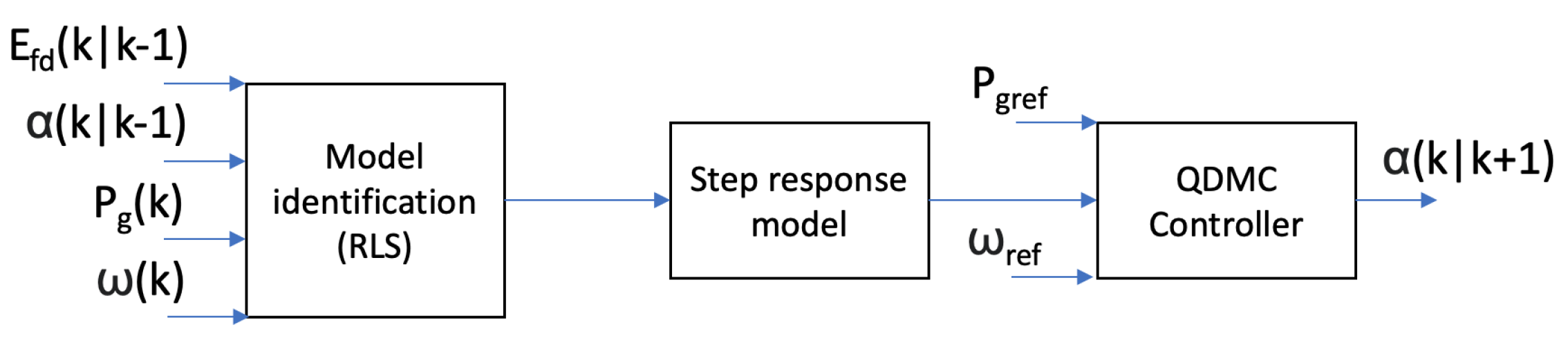
The referred system consists of seven elements: a control object (here: a turbo–generator set consisting of a steam turbine and a synchronous generator on a common shaft), two controllers (the controllers’ variables are described in Table 1), two measuring systems, and two actuating systems (Figure 1), which constitute the final system of interconnected objects (the detailed description of the elements can be found in the previous works [13,14,15,16]. These objects are connected with each other and one of three types of flow occurs on each of these connections [27], namely, the following:
  • Mass flow (valve movement, steam flow);
  • Energy flow (excitation voltage and current, measurement of electrical quantities);
  • Information flow (communication between elements of the control system).
System optimization, which is ubiquitous in every application, is aimed at minimizing these flows and thus saving resources. In order to reduce energy flows (by optimizing actuator operations), it is proposed to use the MPC systems, which allow taking into account control-amplitude-related cost along with other natural constraints imposed on specific signals. Knowledge of the model allows the MPC controller to find a control signal that ensures the smooth operation of actuators, e.g., a control valve, by reducing sudden and violent changes in its opening degree. This aspect of the turbine–generator control system optimization has been addressed in [15] and will not be discussed in this paper.
Solutions for optimizing the use of actuators through event-triggered control, where the controller does not react on a cycle basis (time-triggered) but its operation is event-triggered, can also be found in the literature [4]. The authors are also willing to use such a solution in relation to the control system discussed; however, for the sake of the purity of the argument, it will be omitted, and the considerations will focus on other communication channels.
There are also ST solutions, where the operation of the system is conditioned not by an external event but by calculations inside the system based on a mathematical model. Such a solution could be developed on the basis of calculations using a measurement model, leading to a significant reduction in their number [1]. In such a case, the measurement system itself determines when the next sample should be taken so as not to miss a significant change in the state of the object. Due to the nature of the plant controlled (nuclear power plant), it was decided to abandon this approach. As it is necessary to maintain work safety, it was assumed that the state of the plant had be monitored continuously and that the control might not take place in an open loop (based on the model and the historical signal values).
In the research discussed, the key stress was put only on the connections between sensors and control systems (marked in yellow and orange in Figure 1), and the proposed solution is aimed at minimizing the third of the above-mentioned flows, i.e., the information flow.
While, as mentioned above, the continuous measurement of the turbine set operation parameters should not be abandoned, it is not necessary for the control system to react to all measurement values. Therefore, it is assumed that the communication between the sensor and the control system can be initiated only when the measurement can affect the change in the control signal. Similarly, in the proposed solution, where the control systems additionally exchange information with each other in the form of the developed control signal values, communication between the control systems does not have to be recurrent but only when this communication can influence the operation of the other system.
In either case, it turns out to be problematic that both of these control systems, the turbine and the generator, use the estimation of the parameters of the object model on-line, using the least squares method. Therefore, the influence of an asynchronous communication between the objects on the estimation algorithms should also be taken into account.
The aim of the research described is therefore to determine the conditions to be governed by asynchronous communication triggered by events (what event is to trigger communication, what are the limitations) and to ensure the correct operation of the discussed algorithms after switching to asynchronous event-triggered communication.

3. Model and Methods

3.1. Event-Triggered/Self-Triggered Control Schemes

Commonly used control systems together with measurement and actuation systems operate cyclically. Their operation is triggered at regular intervals. Such time-triggered systems always work, even when their response is not required. Therefore, event-based triggering is proposed to reduce resource consumption (communication link load, CPU load). In this approach, the systems take up work or communicate with each other only when an event requiring their reaction occurs. As a result, the load on the processors or on the communication network is reduced. One extension of this concept is self-triggered systems, in which the triggering event does not come from the outside but results from calculations using the object model. The purpose of using such solutions (both event- and self-triggered) is to reduce the waste of resources (energy, computing power, bandwidth) while minimizing the quality of the system operation, which is already becoming a vital issue, as the control systems are put to their limits, and making use of, for example, energy harvesting, which should be paired with a cautious use of computing power, to optimize energy consumption [1]. The subject of the discussed research is the use of event triggering in the communication between distributed control systems composed of two MPC controllers exchanging information about the calculated control signal, forming a DMPC (distributed MPC) approach.
In the system of concern, a turbo–generator set, there exists an internal interaction: the turbine and the generator are connected by a common shaft on which they are mounted. The way in which they interact results from the values of mechanical moments: the drive torque of the turbine and the operating torque of the generator. The resultant value of these interactions is the rotational speed of the shaft. Increasing the electrical load on the generator causes an increase in the electromechanical torque, a load on the turbine. Any changes in the mechanical torques of the turbine and generator affect the rotational speed of the turbine–generator set. At the same time, the value of the rotational speed of the shaft causes disturbances in the generator’s voltage. Both components of this system, the turbine and generator, usually have two separate controllers. In previous works, it was proposed to use the aforementioned MPC controllers and a communication channel between the controllers, forming a distributed control system, which is intended to better facilitate the prediction of the object’s behavior and thus increase the quality of control.
The MPC framework and the models used have already been described twice in the series of previous Energies papers by the authors, published in the earlier stages of this research; thus, an interested reader is kindly asked to refer to [13,14].
In [13], the results of research on the quality of the distributed control of the cooperating control system of the nuclear power plant turbine set in the form of a pair of QDMC controllers exchanging pieces of information are described. The article describes the solution itself and an analysis of its robustness. In [14], the idea of using the MPC technology to take into account additional measurements from the plant is described. This was undertaken in order to take into account the possibilities offered by the power system stabilizer (PSS) in classic control systems and to extend the PSS idea to the MPC control systems.
Previous works concerned the replacement of classic control systems based on extensive PID control with additional modules, such as a power system stabilizer, with model predictive control. The use of model-based control was aimed at optimizing the operation of the control system. In addition, it was decided to extend the models used by the two controllers (turbine and generator) in such a way as to take into account additional information exchanged between the control systems. The methods of determining the control quality (quality indices) and the impact of the proposed solution on the quality, as well as the analysis of the impact of disturbances on the operation quality of the system of two communicating MPC controllers, are described in the above-mentioned works.
The communication between controllers (described in [13,14]) takes place cyclically (time-triggered) at every algorithm iteration, but the results of this paper are based on the assumption that this communication is auxiliary and is required only when these systems perform some actions changing the control signal. In the case of steady-state operation, communication is not required and can be minimized or even eliminated altogether. This approach should drastically reduce communication while maintaining control quality and further improving the proposed solution, which is the main focus of the research.

3.2. Recursive Least Squares Scheme

Due to the nonlinearity of the object, the parameters of the model defined in this way should be identified online depending on the change in the operating point of the turbo–generator set as it has been presented in our prior works [28,29]. In this paper, however, the RLS was used for these purposes. Recursive least squares is the algorithm that recursively finds the parameter estimates to a weighted linear least squares cost function related to an input signal [30], on the contrary to other algorithms such as the least mean squares one focused on main square error. At the cost of computational complexity, it offers fast convergence.
For the purposes of implementing the control algorithms, input–output models describing the dynamics of the turbine–generator set were used, the parameters of which were updated at each simulation step using the recursive least squares method. The RLS algorithm enables the determination of an unknown model’s parameters based on a set of input and output measurement data [31]. The RLS algorithm was chosen due to the simplicity of calculations, ease of implementation for the estimation of the parameters of the online model, and the possibility of taking into account the past input and output values of the object (as opposed to, e.g., the gradient method). Subsequently, based on the identified simplified model, a nonparametric step response model is determined for the proposed QDMC control system described in this paper (or an alternative algorithm such as DMC [28]). The sample use of a step response model can be easily traced in the literature: see [32]. The article proposes the adaptation of the parameters of the online model to the operating point of the object using the recursive least squares method. Solutions based on a set of soft-switch models (e.g., fuzzy model [33]) defined for specific operating points are characterized by worse accuracy at intermediate points between these points as all the values are the average of the two neighboring points. In the case of nonlinear systems, it does not have to always be true. In this case, the model output is a combination of the object linear model outputs for adjacent work points and may deviate from the nonlinear model output. Therefore, it is proposed to use the mechanism of adapting parameters of online models. This approach allows the minimization of the modeling error for a wide range of changes in the operating point.
The linear model of an object for the purposes of the RLS algorithm can generally be represented as (1).
y ( k ) = ϕ ( k ) T θ ( k )
where the following notation is adopted:
  • y ( k ) —the explained variable (object output), y ( k ) = [ P g ( k ) , U g ( k ) , ω ( k ) ] ;
  • ϕ ( k ) —a vector of explanatory variables (predictors), consisting of the object’s previous input and output values;
  • θ ( k ) —vector of regression coefficients.
The simplified model of the turbine set discussed in this paper can be presented in a similar way (2)–(4).
P g ( k ) = ϕ 1 ( k ) T θ 1 ( k )
U g ( k ) = ϕ 2 ( k ) T θ 2 ( k )
ω ( k ) = ϕ 3 ( k ) T θ 3 ( k )
where:
  • ϕ 1 ( k ) = [ α ( k ) , α ( k 1 ) , , α ( k d A D ) , E f d ( k ) , E f d ( k 1 ) , , E f d ( k d E ) , P g ( k 1 ) , P g ( k 2 ) , , P g ( k d C ) ] ,
  • ϕ 2 ( k ) = [ α ( k ) , α ( k 1 ) , , α ( k d A G ) , E f d ( k ) , E f d ( k 1 ) , , E f d ( k d H ) , P g ( k 1 ) , U g ( k 2 ) , , U g ( k d F ) ] ,
  • ϕ 3 ( k ) = [ α ( k ) , α ( k 1 ) , , α ( k d A N ) , E f d ( k ) , E f d ( k 1 ) , , E f d ( k d P ) , P g ( k 1 ) , ω ( k 2 ) , , ω ( k d M ) ] ,
  • θ 1 ( k ) = [ a 1 , a 2 , , a 21 ] ,
  • θ 2 ( k ) = [ b 1 , b 2 , , b 21 ] ,
  • θ 3 ( k ) = [ c 1 , c 2 , , c 21 ] .
It was decided to choose such a model due to the simplicity of the structure and the speed of calculations, and the seventh order of the model was adopted based on the analysis of the object complexity in each of the input–output paths. This value was chosen based on the complexity of the turbine model (series of two inertia) and the generator (fifth-order composite model). Despite the fact that the greatest complexity of the model occurs only in the path of the control valve opening—the generator voltage, it was decided to adopt a priori the 7th order of the model in all analyzed information processing paths ( d A D , d A G , d A N , d E , d H , d P , d C , d D , d F equal 7, as orders of corresponding polynomials, according to notations in the equations directly above). It arose from an attempt to find a model that would reflect the dynamics of the object well and at the same time would not be too extensive. The results of experimental studies confirmed that this choice was correct.
Individual coefficients of the model (i.e., matrices θ n = [ θ 1 , θ 2 , θ 3 ] ) are calculated using the recursive least squares method:
θ n ( k ) = θ n ( k 1 ) + K ( k ) ϵ ( k ) ,
ϵ ( k ) = y ( k ) ϕ T θ ^ ( k 1 ) ,
P ( k ) = 1 λ P ( k 1 ) P ( k 1 ) ϕ ( k ) ϕ T ( k ) P ( k 1 ) λ + ϕ T ( k ) P ( k 1 ) ϕ ( k ) ,
K ( k ) = P ( k 1 ) ϕ ( k ) λ + ϕ T ( k ) P ( k 1 ) ϕ ( k ) ,
where:
  • K—the gain matrix;
  • ϵ —the error between the model output and actual value;
  • θ ^ —the model parameter estimates matrix;
  • ϕ —a vector of explanatory variables (predictors), consisting of the object’s previous input and output values;
  • λ —the forgetting factor.
All initial parameters for the RLS algorithm were set to 1 in the first run of the algorithm. After that, the final results from the first simulation were used as initial values. This was based on the assumption that, although the parameters vary depending on the operation point and need to be identified online, one of those operation points would be closer to the solution than completely random values.

3.3. Object Model Used under MPC/RLS Framework

The quadratic dynamic matrix control scheme and the corresponding structure of the generator have been presented in Figure 2 and Figure 3, in the form on nonparametric models based on their step responses. The parameters of these models are estimated on the basis of a black-box approach, related to Formulae (9)–(11), identified in the online manner using the recursive least squares [31] scheme, to ensure coherency between the model, and the behavior of the system in different operating conditions, with appropriate input–output data measurements available. This approach is typically used when we are not interested in explaining the model structure, as presented simply by functional relations between input and output signals and put together with parameter models. As for the absence of a physical interpretation of these parameters, the aim of such an approach is simply to present some relationships, trends in process behavior, and what makes this approach appealing and effective.
The above-mentioned nonparametric model, suited for the quadratic dynamic matrix control scheme, is given in the form allowing its sampled-data control use, as follows:
P g ( k ) = j = 1 n a ( j ) P g ( k 1 j ) + j = 1 n b ( j ) α ( k j ) + j = 1 n c ( j ) E f d ( k j ) ,
U g ( k ) = j = 1 n d ( j ) U g ( k 1 j ) + j = 1 n e ( j ) α ( k j ) + j = 1 n f ( j ) E f d ( k j ) ,
ω ( k ) = j = 1 n g ( j ) ω ( k 1 j ) + j = 1 n h ( j ) α ( k j ) + j = 1 n i ( j ) E f d ( k j ) ,
with turbine parameters a, b, c, d, e, f, g, h, and i obtained on the go with the use of a RLS algorithm. For the sake of brevity, a detailed discussion concerning the correct values of parameters has been presented in [34], concerning both the generator and the turbine. As far as the predictive controller of a synchronous generator is concerned, the presented model is used again, with the difference that another range of parameters is being identified at the same time, as per the independence of the models.
The presented models (9)–(11) use n samples’ values, with an arbitrary choice of n = 7 , as a result of modeling a turbine–generator model in the α U g flow. The presented order is a solution avoiding oversimplified models with low n and those which are overparametrized. Summing the degrees of polynomials, a steam turbine (degree 2) [35] and the one of a synchronous generator (degree 5) [36], the same degrees as in our prior papers are used [13,14,15].
The parameters of the turbine and the generator have been presented in our prior publications in Energies and are also available in the literature, see, e.g., [37], related to the parameters of the GTHW-600 generator and 4CK-465 turbine. The model and its parameters are omitted here for the sake of brevity.

3.4. Key Performance Indicators

The quality indicators used to assess the control quality here must take into account the impact of the amplitude and frequency of the voltage on it. To achieve the latter, ISE- and ITSE-related indices are used. The following quantities are taken into account: the voltage U g , power P g , or frequency ω . The other index, ITSE, assesses the accuracy of the voltage amplitude and frequency stabilization along with taking the stabilization time into account. Should disturbances be taken into consideration, the latter index takes not only the speed of transients into account but also the rate of their potential attenuation.

4. Analysis of Simulation Results

In order to present the discussed solution, a series of simulation test studies were performed using the Matlab/Simulink environment. The responses of two control systems to the change in the trajectory of the set’s active power (turbine’s controller) with voltage stabilization at the set value (generator’s controller) were compared. Both systems consisted of identical MPC controllers (with control horizons for the generator and the turbine s G / s T equal to one and prediction horizons p G = 20 and p T = 40 ) that control identical plants. The control horizon defines the number of subsequent steps the controller uses to determine the control signal values. In the considered control system with the identification of parameters of the nonlinear plant online, the model changes in each cycle of the algorithm. Therefore, it was decided to assume the control horizon was equal to 1 and define the control signal only for a given moment. In the proposed solution, the control horizon equal to 1 was selected, which means that only one value of the control signal is calculated in each step and it is kept at that value throughout the prediction horizon. This is due to two factors—firstly, due to the nonlinearity of the object and the use of a simplified linear model, the control prediction in the further horizon would be subject to an error related to the change in the system operating point. Thanks to the use of an online parameter estimation, the model is updated at each step and for the current model the algorithm calculates a single value of the control signal. Secondly, knowledge of this single value is sufficient to predict, based on the model, the behavior of the object in subsequent moments, which reduces communication needs. The alternative of transmitting the entire trajectory of future controls (in the case of larger control horizons) between the control systems was abandoned in favor of transmitting information only about a single value of the control signal. Communication between the controllers takes place at every control step, so information about a possible change in the control signal is immediately available. This allows you to limit the amount of information sent while allowing the two control systems to cooperate. The next execution of the algorithm works on the basis of the updated model, determining the new value of the control signal. System A used an event-triggered (ET) communication solution, while system B worked in a time-triggered communication mode (no ET).
To explore different communication strategies and to better relate the results to previous works [16], two different types of communication were taken into consideration: a one-way communication, where only the turbine’s controller shares its control signal ( α ), and a two-way communication, where both the controllers share their control signals with one another. Previous research shows that one-way communication in the opposite direction, i.e., the exchange of only the generator’s control signal ( E f d ), gave no significant improvement in quality and therefore will be skipped in this paper. The results for the one-way communication are presented in Figure 4. The results for the two-way communication are presented in Figure 5. Table 2 contains results for both cases in a tabular form. The concept of a one- and a two-way communication between two MPC controllers in the nuclear power plant’s control system is described in [16]. The ISE and ITSE integral quality indices [15] were used to present the results in a quantitative form, as in our previous papers, to keep the results uniformly presented. In [13], the authors analyze different types of disturbances and the robustness of the system consisting of two MPC controllers exchanging information. The work contains description of different scenarios in which the system deals with different operation points and operates under different conditions. As the focus of this paper is to focus on ET communication, only one scenario of the power plant operation will be used. In the research, it was assumed that communication between the control systems occurs periodically every 0.01 s (time period equal to the controllers’ sampling time). This corresponds to the cyclic transmission of information through the network on every control algorithm execution, while possible transmission delays caused by network load from other devices are omitted. In the case of a time-triggered system, the exchange of information between two controllers (information about the current value of the opening α and excitation voltage E f d ) is sent at any time instant (every 0.01 s). In the case of the event-triggered system, rules have been introduced that cause the signal update to be sent only when a certain threshold is exceeded. In the remaining time instants, the second controller uses the previously obtained value. The triggering condition is defined as follows: the turbine control system sends an update when the change in the control signal α exceeds 1% (12) and the controller of the generator sends an update when the control signal E f d exceeds 0.00001 p.u. (13).
Δ α ( k ) = | α ( k ) α ( k 1 ) | 1 %
Δ E f d ( k ) = | E f d ( k ) E f d ( k 1 ) | 0.00001   p . u .
As a result, the whole communication between the two controllers stops when the plant operates in a steady state and no control signal updates are made or necessary. Since the turbine–generator set is a nonlinear plant and the MPC linear control system is used in the discussed solution, it was decided to use online identification using the recursive least squares method (RLS—the method is described in detail in the next section). Parameter estimation is carried out continuously and therefore it is important that the time of discrepancies between the actual signal values and the values used by the identification system, as well as the size of these discrepancies, is minimal. This makes it necessary to communicate even the smallest signal changes, which allows the RLS algorithm to better keep up with the correct parameters of the model. The latter causes an increase in the number of messages sent between the systems in relation to systems with differently defined communication triggering conditions. However, due to the fact that there are periods of steady-state operation, when signal changes are minimal, a compromise is reached whereby information is exchanged frequently during the intense operation of the control system periods, which allows the RLS algorithm and the controller to work, and during steady-state operation, when signals change slightly, the communication is drastically reduced.
In [16], experiments with two-way and one-way communication ( α signal only or E f d signal only) are described. The deterioration in quality was visible for all quantities: the voltage, power, and angular velocity. The deterioration in the quality of voltage stabilization was much greater than in the case of the active power control or stabilization of the angular velocity. The processes taking place in the turbine are much slower than the processes taking place in the generator. Therefore, temporary changes in the load torque on the turbine–generator set’s shaft have a smaller impact on the turbine control than the changes in the angular velocity of the shaft (caused by the turbine operation) have on the generator voltage. Therefore, the article focuses much more on the deterioration in the generator voltage quality, which does not mean that the other parameters do not change either.
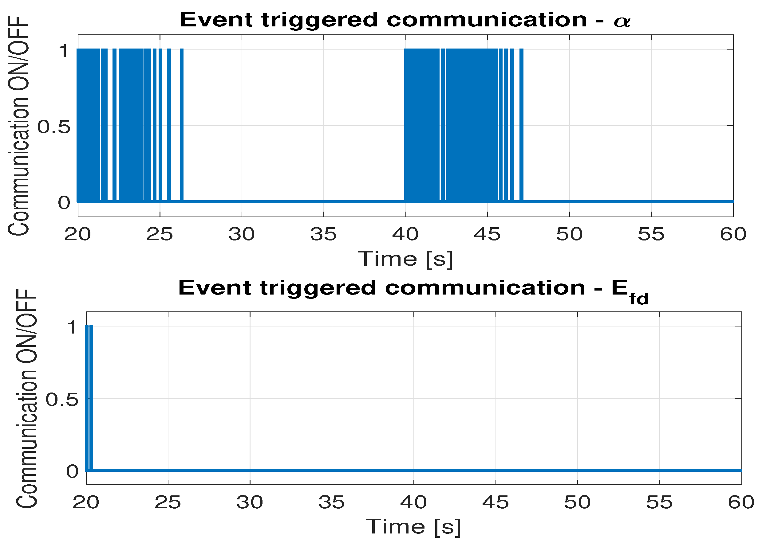
Additionally, Figure 6 shows the communication/no communication signal for one-way communication, while Figure 7 shows the same for two-way communication. Value 1 marks the time instants when the communication occurs and 0 marks the instances with no communication for two signals exchanged between the control systems: the control valve opening α and excitation voltage E f d . Table 3 shows the percentage of time in which the communication occurred and the time with no communication.
In order to illustrate the impact of incorrectly selected triggering conditions, an additional simulation was performed. The new triggering condition is defined as follows: the turbine control system sends an update when the change in the control signal α exceeds 10% (14) and the controller of the generator sends an update when the control signal E f d exceeds 0.1 p.u. (15).
Δ α ( k ) = | α ( k ) α ( k 1 ) | 10 %
Δ E f d ( k ) = | E f d ( k ) E f d ( k 1 ) | 0.1   p . u .
Figure 8 presents the results of the experiment, while the performance indices are shown in Table 4.
The lack of a continuous exchange of information and current measurements provided to the RLS algorithm results in significant oscillations of the generator voltage U g . As was shown in [16], one of the α communication channels has a significant impact on the operation of the cooperating turbine set control system. Therefore, despite the fact that the operation of both communication channels was significantly disrupted, a significant deterioration in quality was noted only in the case of the generator voltage and not the active power P g or rotational speed ω g control. This deterioration is also visible in the change in ISE/ITSE parameter values. These results show the necessity of selecting good triggering conditions in ET technology. Although the use of event triggering can significantly optimize the exchange of information, the wrong choice of triggering events can negatively affect the way the entire control system works.
Figure 9 and Table 5 show the triggering times under changed conditions. The selection of more strict triggering conditions (signal changes must be significantly larger) has led to less frequent communication between the control systems. This behavior causes the cooperating system to work with outdated information, which causes a deterioration in the control quality.
The third experiment was performed using the original triggering conditions, ensuring the correct system operation in different operating conditions. In order to show the increase in the frequency of communication depending on the regime in which the turbine set operates, the frequency of changes in the set value of active power P g was increased to 2 s. Thanks to this, in the presented simulation period of 40 s, the number of changes in the set value was increased from 2 to 20, forcing more frequent communication. The obtained results are presented in Figure 10 and Table 6. As in the case of the experiment with the slower pace of the set trajectory of active power P g change, both systems (with and without ET) behave identically. No significant deterioration in quality was observed. These results are also confirmed by the integral quality indicators.
Figure 11 and Table 7 show the triggering time of the information exchange in both communication channels ( α and E f d ) and the ratio of the time in which the communication occurred to the total time of simulation. As expected, the significant increase in the dynamics of the setpoint change led to a greater need for information exchange. Therefore, the control systems communicated more often, which significantly affected the percentage of communication time. This illustrates how changing the test scenario affects the effectiveness of the ET solution. Nevertheless, even in such a demanding case, the use of event triggering technology allows you to limit the amount of information sent over the network.
Results for cooperative predictive control systems with different parameter sets (without ET) can be found in [15].
In addition, the parameters obtained by the RLS algorithm for the system with and without event-triggered communication were compared (event-triggered and time-triggered). Table 8 shows sample results for the generator model (21 parameters) obtained during the experiment discussed above. Figure 12 shows a few of the parameters changed by the RLS algorithm during the time after the change in the plant’s operating point (step change of the set active power) in the 20th second of the simulation.
The introduction of the ET solution did not change the accuracy of the model parameter estimation, as the values of the parameters for both control systems—event-triggered and time-triggered—are identical. The proposed solution ensures that the identification system always works on accurate measurements as to the error determined by the communication trigger threshold. Taking into account the need to provide appropriate data for the correct operation of the algorithm, very low communication trigger thresholds were adopted, and the information exchange breaks did not affect the accuracy of the parameter estimation. Figure 12 shows how the parameters are adapted online (on a sample set of six parameters as an example) to reflect the changes in the plant’s behavior under different operation conditions. In this case, the change was caused by altering the operating point, but the same behavior is beneficial in the case of usage-related changes, such as, for example, the tear and wear of the turbine’s bearings. These results confirm that the use of the ET technology with proper triggering events does not negatively affect the operation of the RLS algorithm.
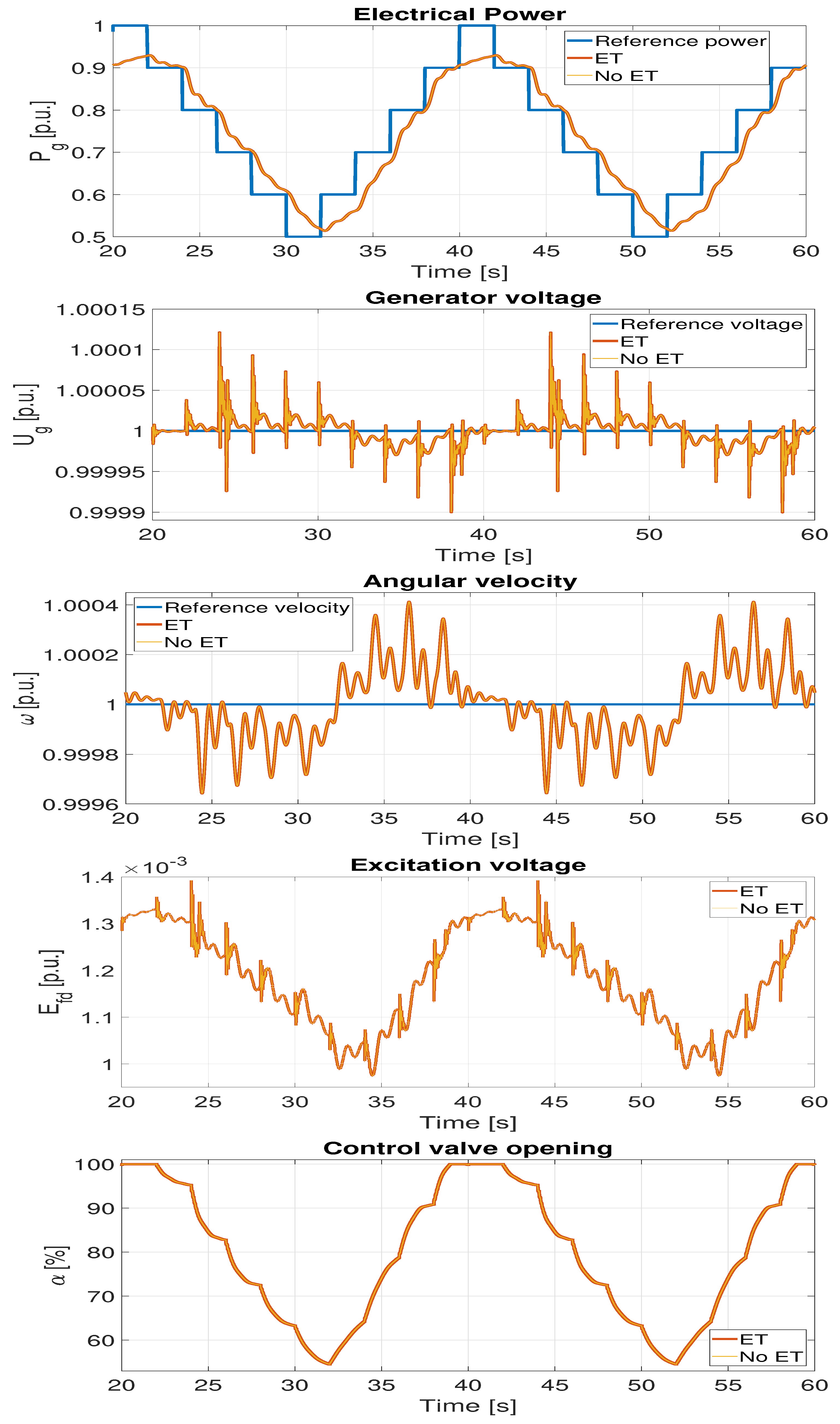
The analyses of electrical quantity waveforms (power, voltage amplitude, voltage frequency) and integral ISE/ITSE quality indices do not show any reduction in control quality due to limited communication. The reduction in control quality is imperceptible, and the systems respond in a similar way. Both Σ I S E and Σ I T S E indices are equal for both cases (ET and no ET), as well as separate sub-components of those sums, i.e., I S E / I T S E P g , I S E / I T S E U g , and I S E / I T S E ω . These results confirm that the use of the ET technology with proper triggering events does not negatively affect the quality of control (measured by the ISE/ITSE indices).
However, the obtained results show that it is possible to reduce the communication effort (reducing the load on the communication network and the CPU load). The limitation for two-way communication reaches 89.5% (average index values for both signals) and it reaches 84.5% for one-way communication. This is related to long periods of time in which the control system is only to stabilize the power and voltage of the generator, e.g., from the 27th second to the 40th second of the simulation for signal α or from the 22nd second to the 40th second for signal E f d . In such a situation, the controllers maintain a constant value of the control signals and it is not necessary to communicate the signal update. In the moments of changing the set value (20th and 40th seconds of the simulation) when there is a frequent change of the value of the control signal, communication is frequent, which allows for the ensurance that the quality is comparable to the quality of a system with continuous communication. During this period, both systems, event-triggered and time-triggered, communicate at each MPC execution, i.e., every 0.01 s. This type of behavior allows for high control accuracy by continuously communicating during times of frequent changes in control signals while strongly limiting communication in steady states.
The percentage of the time with no communication also depends on the performed experiment. For the cases where the changes in the set value are more dynamic, the need for communication will be bigger resulting in fewer no-communication periods up to communication at every step (100%) for the cases that need constant control. However, regardless of the conducted experiment, including the dynamics of changes in the set value or disturbances, this solution limits the exchange of information as long as the operation of the system stabilizes and it works in a steady state. Such a large communication reduction is possible because communication between both control systems is auxiliary and not always needed. In the case of event-triggered control or measurements—especially in the case of a critical infrastructure facility, e.g., a power plant—such a large reduction might not be possible. As the obtained results show, it was possible to significantly reduce communication while maintaining the level of control quality, in the case discussed. In addition, it was possible to avoid problems with the RLS method used in the solution, which requires current signal values to correctly estimate the model parameters. By using trigger conditions that update the information with minimal changes in the control signal, the RLS algorithm always works with accurate values. Between the trigger events, the last sent values are used, which only slightly deviate from the real ones. The resulting, calculated parameters for both event-triggered and time-triggered communication are the same within the accepted accuracy. This approach allows one to maintain control quality while reducing the communication and CPU load during steady-state operation. This paper analyzes only the impact of event triggering on communication between control systems. This is to isolate this special case of ET operation and enable analysis of its work in isolation. The results obtained during the simulation tests show a significant reduction in the amount of information sent, which translates into a lower load on the communication channels and a lower CPU load. Unfortunately, this special case of communication (exchange of control signal values between controllers) does not generate large loads on its own, so even such a significant reduction in the number of sent messages does not have to make a huge difference for the entire communication network. It is assumed, however, that in the case of a cooperative control system, the measurements and/or operation of the control system can be triggered by events (event-triggered) or based on the model (self-triggered). In addition, the same communication network can be used by other control systems or other devices exchanging their own messages. Therefore, it is assumed that the extension of the use of ET and ST approaches to other communication channels may allow, thanks to the scale effect, a significant reduction in the use of resources, i.e., the network bandwidth or CPU load in the entire communication network.

5. Conclusions

This article proposes the use of event-triggered communication between sensors and controllers in the control system of the turbine–generator set of a nuclear power plant. This solution reduces the amount of information sent over the network, which reduces the network load. The communication generated by the control systems was reduced by about 90% on average. It was possible by completely stopping communication in a steady state, i.e., giving up sending signals if they are almost constant (they change by values lower than the adopted threshold). The multiplicity of this quality indicator, which defines the ratio of the communication time to the entire simulation time, can vary significantly depending on the experiment and the occurring disturbances. Nevertheless, the obtained results confirm that it is possible to maintain the control quality while limiting the amount of information by resigning from the cyclical time-triggered transmission of signals. Moreover, limiting the execution moments of the algorithm to only asynchronous moments related to the event-triggered communication also reduces the load on the computing units of network devices. Since in the discussed case the estimation of the parameters of the online model is performed by the recursive least squares method, it is necessary to minimize the discrepancies between the actual signal values and the values used by the identification system as well as the size of these discrepancies. This makes it important to communicate even the smallest changes in signals, which allows the RLS algorithm to better keep up with the correct parameters of the model. Therefore, it was decided to adopt a communication strategy in which information about a minimal signal change (exceeding a defined threshold) leads to sending its update. As a result, the identification system is based on the exact values of the signals (as to the error associated with the threshold) and, at the same time, it has become possible to significantly reduce the amount of information exchanged in periods of time when the signals are constant. The results confirm that the novelty presented in the article, in the form of event-triggered communication between two regulators of the turbine–generator set, allows the quality of control achieved by the system to be maintained with continuous communication (time-triggered) while significantly reducing the number of messages sent, by an average of approx. 90%.
The next stage of research on optimizing the operation of the turbo–generator set control system would be the application of the discussed event-triggered communication mechanism, event-triggered control, and self-triggered measurement. The aim of it would be to reduce communication in all possible communication channels as this would contribute to reducing communication between sensors and control systems and between between controllers and actuators. While the reduction in the amount of information sent in one channel may not have a significant impact on the network load, it is assumed that the widespread use of ET and ST solutions can bring a noticeable difference due to the scale effect.

Author Contributions

Conceptualization, P.S., B.C. and D.H.; methodology, P.S.; software, P.S.; validation, P.S., B.C., T.A.R., D.Z. and D.H.; formal analysis, D.H. and P.S.; investigation, B.C. and P.S.; resources, P.S. and B.C.; writing—original draft preparation, P.S., B.C. and D.H.; writing—review and editing, B.C., D.H., T.A.R. and D.Z.; visualization, P.S.; supervision, D.H. and B.C.; funding acquisition, D.H. All authors have read and agreed to the published version of the manuscript.

Funding

This research was funded in part by the Poznan University of Technology under Grant 214/SBAD/0241.

Conflicts of Interest

The authors declare no conflict of interest.

Nomenclature

α Control valve opening [%]
ω Generator’s angular speed [pu]
E f d Excitation voltage [pu]
P g Active power [pu]
p G Generator QDMC controller’s prediction horizon [-]
p T Turbine QDMC controller’s prediction horizon [-]
U g Turbine QDMC controller’s prediction horizon [-]
DMCDynamic Matrix Control—a version of an MPC algorithm
DMPCDistributed MPC
ISEIntegral of Squared Error
ITSEIntegral of Time-weighted Squared Error
MPCModel Predictive Control
PSSPower System Stabilizer
QDMCQuadratic Dynamic Matrix Control—a version of an MPC algorithm
RLSRecursive Least Squares

References

  1. Heemels, W.; Johansson, K.; Tabuada, P. An introduction to event-triggered and self-triggered control. In Proceedings of the 2012 IEEE 51st IEEE Conference on Decision and Control (CDC), Maui, HI, USA, 10–13 December 2012. [Google Scholar] [CrossRef] [Green Version]
  2. Mahmoud, M.S.; Sabih, M. Networked event-triggered control: An introduction and research trends. Int. J. Gen. Syst. 2014, 43, 810–827. [Google Scholar] [CrossRef]
  3. Ge, X.; Han, Q.L.; Zhang, X.M. Dynamic Event-triggered Control and Estimation: A Survey. Int. J. Autom. Comput. 2021, 18, 857–886. [Google Scholar] [CrossRef]
  4. Brunner, F.D.; Heemels, W.; Allgöwer, F. Robust self-triggered MPC for constrained linear systems. In Proceedings of the 2014 European Control Conference (ECC), Strasbourg, France, 24–27 June 2014. [Google Scholar] [CrossRef]
  5. Brunner, F.D.; Heemels, W.; Allgöwer, F. Robust Event-Triggered MPC for Constrained Linear Discrete-Time Systems with Guaranteed Average Sampling Rate. IFAC-Pap. 2015, 48, 117–122. [Google Scholar] [CrossRef]
  6. Brunner, F.D.; Heemels, W.; Allgöwer, F. Robust self-triggered MPC for constrained linear systems: A tube-based approach. Automatica 2016, 72, 73–83. [Google Scholar] [CrossRef]
  7. Mazo, M.; Anta, A.; Tabuada, P. On self-triggered control for linear systems: Guarantees and complexity. In Proceedings of the 2009 European Control Conference (ECC), Budapest, Hungary, 23–26 August 2009. [Google Scholar] [CrossRef]
  8. Tabuada, P. Event-Triggered Real-Time Scheduling of Stabilizing Control Tasks. IEEE Trans. Autom. Control 2007, 52, 1680–1685. [Google Scholar] [CrossRef] [Green Version]
  9. Anta, A.; Tabuada, P. To Sample or not to Sample: Self-Triggered Control for Nonlinear Systems. IEEE Trans. Autom. Control 2010, 55, 2030–2042. [Google Scholar] [CrossRef] [Green Version]
  10. Eqtami, A.; Heshmati-alamdari, S.; Dimarogonas, D.V.; Kyriakopoulos, K.J. A self-triggered Model Predictive Control framework for the cooperation of distributed nonholonomic agents. In Proceedings of the 52nd IEEE Conference on Decision and Control, Firenze, Italy, 10–13 December 2013. [Google Scholar] [CrossRef]
  11. Trimpe, S.; Buchli, J. Event-based estimation and control for remote robot operation with reduced communication. In Proceedings of the 2015 IEEE International Conference on Robotics and Automation (ICRA), Seattle, WA, USA, 26–30 May 2015. [Google Scholar] [CrossRef]
  12. Shi, D.; Elliott, R.J.; Chen, T. Event-based state estimation of discrete-state hidden Markov models. Automatica 2016, 65, 12–26. [Google Scholar] [CrossRef]
  13. Sokólski, P.; Rutkowski, T.A.; Ceran, B.; Horla, D. Robustness Analysis of a Distributed MPC Control System of a Turbo-Generator Set of a Nuclear Plant–Disturbance Issues. In Automation 2021: Recent Achievements in Automation, Robotics and Measurement Techniques; Springer: Berlin/Heidelberg, Germany, 2021. [Google Scholar] [CrossRef]
  14. Sokólski, P.; Rutkowski, T.A.; Ceran, B.; Horla, D.; Złotecka, D. Power System Stabilizer as a Part of a Generator MPC Adaptive Predictive Control System. Energies 2021, 14, 6631. [Google Scholar]
  15. Sokólski, P.; Rutkowski, T.; Ceran, B.; Horla, D.; Złotecka, D. Numbers, Please: Power- and Voltage-Related Indices in Control of a Turbine-Generator Set. Energies 2022, 15, 2453. [Google Scholar] [CrossRef]
  16. Sokólski, P.; Rutkowski, T.; Ceran, B.; Horla, D.; Złotecka, D. The Influence of Cooperation on the Operation of an MPC Controller Pair in a Nuclear Power Plant Turbine Generator Set. Energies 2022, 15, 6702. [Google Scholar] [CrossRef]
  17. van Horssen, E.P.; van Hooijdonk, J.A.A.; Antunes, D.; Heemels, W.P.M.H. Event- and Deadline-Driven Control of a Self-Localizing Robot With Vision-Induced Delays. IEEE Trans. Ind. Electron. 2020, 67, 1212–1221. [Google Scholar] [CrossRef]
  18. Mousavi, S.H. Event-Triggered Control Systems; Department of Electrical and Computer Engineering, University of Alberta: Edmonton, AB, Canada, 2016. [Google Scholar]
  19. Petri, E.; Postoyan, R.; Astolfi, D.; Nešić, D.; Heemels, W.P.M.H. Event-triggered observer design for linear system. In Proceedings of the 2021 60th IEEE Conference on Decision and Control (CDC), Austin, TX, USA, 14–17 December 2021. [Google Scholar] [CrossRef]
  20. Nowzari, C.; Garcia, E.; Cortes, J. Event-Triggered Communication and Control of Networked Systems for Multi-Agent Consensus. Automatica 2019, 105, 1–27. [Google Scholar] [CrossRef] [Green Version]
  21. Scheres, K.J.; Dolk, V.S.; Chong, M.S.; Postoyan, R.; Heemels, W.M.H. Distributed Periodic Event-Triggered Control of Nonlinear Multi-Agent Systems. IFAC-Pap. 2022, 55, 168–173. [Google Scholar] [CrossRef]
  22. Ławryńczuk, M.; Marusak, P.M.; Chaber, P.; Seredyński, D. Initialisation of Optimisation Solvers for Nonlinear Model Predictive Control: Classical vs. Hybrid Methods. Energies 2022, 15, 2483. [Google Scholar]
  23. Lehmann, D.; Henriksson, E.; Johansson, K.H. Event-triggered model predictive control of discrete-time linear systems subject to disturbances. In Proceedings of the 2013 European Control Conference (ECC), Zurich, Switzerland, 17–19 July 2013; pp. 1156–1161. [Google Scholar] [CrossRef]
  24. Yoo, J.; Molin, A.; Jafarian, M.; Esen, H.; Dimarogonas, D.V.; Johansson, K.H. Event-triggered model predictive control with machine learning for compensation of model uncertainties. In Proceedings of the 2017 IEEE 56th Annual Conference on Decision and Control (CDC), Melbourne, VIC, Australia, 12–15 December 2017; pp. 5463–5468. [Google Scholar] [CrossRef]
  25. Yoo, J.; Johansson, K.H. Event-Triggered Model Predictive Control With a Statistical Learning. IEEE Trans. Syst. Man Cybern. Syst. 2021, 51, 2571–2581. [Google Scholar] [CrossRef]
  26. He, N.; Du, J.; Xu, Z.; Chen, J. Event-triggered MPC for linear systems with bounded disturbances: An accumulated error based approach. IET Control Theory Appl. 2022, 16, 816–827. [Google Scholar] [CrossRef]
  27. Lovera, M. Control-oriented Modelling and Identification: Theory and practice. In Control, Robotics and Sensors; The Institution of Engineering and Technology: London, UK, 2015. [Google Scholar] [CrossRef]
  28. Sokólski, P.; Rutkowski, T.; Duzinkiewicz, K. The QDMC Model Predictive Controller for the Nuclear Power Plant Steam Turbine Control. In Proceedings of the KKA 2017—The 19th Polish Control Conference, Kraków, Poland, 18–21 June 2017; Volume 577, pp. 241–250. [Google Scholar] [CrossRef]
  29. Sokólski, P.; Rutkowski, T.; Duzinkiewicz, K. The distributed model predictive controller for the nuclear power plant turbo-generator set. In Proceedings of the 22nd International Conference on Methods and Models in Automation and Robotics, Miedzyzdroje, Poland, 28–31 August 2017. [Google Scholar] [CrossRef]
  30. Monson, H. Chapter 9.4: Recursive Least Squares. In Statistical Digital Signal Processing and Modeling; John Wiley & Sons: Hoboken, NJ, USA, 1996. [Google Scholar]
  31. Hakvoort, R. System Identification for Robust Process Control: Nominal Models and Error Bounds. Ph.D. Thesis, Technische Universitet Delft, Delft, The Netherlands, 1994. Available online: https://ui.adsabs.harvard.edu/abs/1994PhDT........16H (accessed on 1 March 2023).
  32. Ławryńczuk, M. Dynamic Matrix Control Algorithm Based on Interpolated Step Response Neural Models. In Proceedings of the Artifical Intelligence and Soft Computing: 10th International Conference, ICAISC 2010, Zakopane, Poland, 13–17 June 2010; pp. 297–304. [Google Scholar]
  33. Sokólski, P.; Rutkowski, T.; Duzinkiewicz, K. Simplified, multiregional fuzzy model of a nuclear power plant steam turbine. In Proceedings of the 2016 21st International Conference on Methods and Models in Automation and Robotics (MMAR), Miedzyzdroje, Poland, 29 August–1 September 2016; pp. 379–384. [Google Scholar] [CrossRef]
  34. Sokólski, P.; Rutkowski, T.; Duzinkiewicz, K. The excitation controller with gain scheduling mechanism for synchronous generator control. In Proceedings of the 2015 20th International Conference on Methods and Models in Automation and Robotics (MMAR), Miedzyzdroje, Poland, 24–27 August 2015; pp. 23–28. [Google Scholar] [CrossRef]
  35. Power System Dynamic Performance Committee. Dynamic Models for Turbine–Governors in Power System Studies; Technical Report PES-TR1; IEEE Power Energy Society: Piscataway, NJ, USA, 2013; p. 117. Available online: https://site.ieee.org/fw-pes/files/2013/01/PES_TR1.pdf (accessed on 1 March 2023).
  36. Loo, C.; Vanfretti, L.; Liceaga-Castro, E.; Acha, E.E. Synchronous Generators Modeling and Control Using the Framework of Individual Channel Analysis and Design: Part 1. Int. J. Emerg. Electr. Power Syst. 2007, 8, 1638. [Google Scholar] [CrossRef]
  37. Imieliński, A. Model Matematyczny Generatora Synchronicznego dla Potrzeb Symulatora Pełnozakresowego. Ph.D. Thesis, Gdansk University of Technology, Gdańsk, Poland, 1987. (In Polish). [Google Scholar]
Figure 1. Different event-triggered strategies: control (green), measurement (blue), communication (yellow), cooperation (orange).
Energies 16 04962 g001
Figure 2. Turbine QDMC controller’s structure.
Energies 16 04962 g002
Figure 3. Generator QDMC controller’s structure.
Energies 16 04962 g003
Figure 4. Results for controllers with event-triggered communication (ET) and without it (no ET)—one-way communication.
Energies 16 04962 g004
Figure 5. Results for controllers with event-triggered communication (ET) and without it (no ET)—two-way communication.
Energies 16 04962 g005
Figure 6. Time instants in which the communication occurred (communication ON/OFF)—one-way communication.
Energies 16 04962 g006
Figure 7. Time instants in which the communication occurred (communication ON/OFF)—two-way communication.
Energies 16 04962 g007
Figure 8. Results for controllers with event-triggered communication (ET) and without it (no ET)—two-way communication, wrong ET conditions.
Energies 16 04962 g008
Figure 9. Time instants at which the communication occurred (communication ON/OFF)—two-way communication, wrong ET condition.
Energies 16 04962 g009
Figure 10. Results for controllers with event-triggered communication (ET) and without it (no ET)—two-way communication, reference power change every 2 s.
Energies 16 04962 g010
Figure 11. Time instants in which the communication occurred (communication ON/OFF)—two-way communication, reference power change every 2 s.
Energies 16 04962 g011
Figure 12. Change in a few selected generator model parameters due to the RLS algorithm operation.
Energies 16 04962 g012
Table 1. Controller’s variables.
Turbine’s ControllerGenerator’s Controller
Manipulated variablesControl valve opening α Excitation voltage E f d
Controlled variablesActive power P g Generator voltage U g
DisturbancesInternal turbine–generator interactions caused by torque
differences on the common turbine–generator shaft
Table 2. ISE and ITSE indices for controllers with event-triggered (ET) communication and without it (no ET).
One-Way CommunicationETNo ET
ISE P g 5.5540 × 10 3 5.5540 × 10 3
ISE U g 2.0720 × 10 9 2.0720 × 10 9
ISE w 6.9800 × 10 8 6.9800 × 10 8
Σ ISE 5.5541 × 10 3 5.5541 × 10 3
ITSE P g 9.2080 × 10 2 9.2080 × 10 2
ITSE U g 3.3450 × 10 8 3.3450 × 10 8
ITSE w 1.1330 × 10 6 1.1330 × 10 6
Σ ITSE 9.2081 × 10 2 9.2081 × 10 2
Two-way communicationETNo ET
ISE P g 5.8444 × 10 3 5.8444 × 10 3
ISE U g 1.8800 × 10 9 1.8800 × 10 9
ISE w 6.2540 × 10 8 6.2540 × 10 8
Σ ISE 5.8444 × 10 3 5.8444 × 10 3
ITSE P g 9.7050 × 10 2 9.7050 × 10 2
ITSE U g 3.0390 × 10 8 3.0390 × 10 8
ITSE w 1.0170 × 10 6 1.0170 × 10 6
Σ ITSE 9.7051 × 10 2 9.7051 × 10 2
Table 3. Communication time percentage.
One-wayON [%]OFF [%]
α 15.5084.50
Two-wayON [%]OFF [%]
α 16.0583.95
E f d 5.0095.00
Table 4. ISE and ITSE indices for controllers with event-triggered (ET) communication and without it (no ET)—wrong ET conditions.
Two-Way CommunicationETNo ET
ISE P g 5.5841 × 10 3 5.5844 × 10 3
ISE U g 2.0008 × 10 9 1.8800 × 10 9
ISE w 6.2690 × 10 8 6.2540 × 10 8
Σ ISE 5.5842 × 10 3 5.5845 × 10 3
ITSE P g 9.7000 × 10 2 9.7050 × 10 2
ITSE U g 3.2850 × 10 8 3.0390 × 10 8
ITSE w 1.0200 × 10 6 1.0170 × 10 6
Σ ITSE 9.7001 × 10 2 9.7051 × 10 2
Table 5. Wrong ET condition. Communication time percentage.
Two-WayON [%]OFF [%]
α 7.1392.87
E f d 1.1898.82
Table 6. ISE and ITSE indices for controllers with event-triggered (ET) communication and without it (no ET)—reference power change every 2 s.
Two-Way CommunicationETNo ET
ISE P g 1.4010 × 10 1 1.4010 × 10 1
ISE U g 1.1720 × 10 8 1.690 × 10 8
ISE w 8.5830 × 10 7 8.5830 × 10 7
Σ ISE 1.4010 × 10 1 1.4010 × 10 1
ITSE P g 2.7670 × 10 + 0 2.7670 × 10 + 0
ITSE U g 2.4270 × 10 7 2.4210 × 10 7
ITSE w 1.8970 × 10 5 1.8970 × 10 5
Σ ITSE 2.7670 × 10 + 0 2.7670 × 10 + 0
Table 7. Communication time percentage—reference power change every 2 s.
Two-WayON [%]OFF [%]
α 84.3015.70
E f d 15.3584.65
Table 8. Generator model parameters.
Param.Event-TriggeredTime-Triggered
θ 1 0.0858100.085810
θ 2 0.0013000.001300
θ 3 0.0329400.032940
θ 4 0.0224500.022450
θ 5 0.0052810.005281
θ 6 0.0016900.001690
θ 7 −0.000161−0.000161
θ 8 0.9175000.917500
θ 9 0.0723100.072310
θ 10 −0.002283−0.002283
θ 11 0.0034430.003443
θ 12 0.0062980.006298
θ 13 0.0025950.002595
θ 14 0.0009790.000979
θ 15 −0.018220−0.018220
θ 16 0.0068010.006801
θ 17 −0.000251−0.000251
θ 18 −0.000092−0.000092
θ 19 −0.000020−0.000020
θ 20 −0.000006−0.000006
θ 21 0.0000070.000007
Disclaimer/Publisher’s Note: The statements, opinions and data contained in all publications are solely those of the individual author(s) and contributor(s) and not of MDPI and/or the editor(s). MDPI and/or the editor(s) disclaim responsibility for any injury to people or property resulting from any ideas, methods, instructions or products referred to in the content.

