Abstract
Due to their tense mining succession relationship, gob-side roadways may undergo significant deformation under multi-mining pressure. In this article, many methods, such as on-site research, a theoretical analysis, a numerical simulation and an industrial experiment, are used to research the mechanism of asymmetric floor heave in a gob-side coal roadway affected by mining pressure during the mining of extra-thick coal seams. Our main research is as follows: (1) By monitoring the floor deformation in the roadway on site, it is concluded that the roadway floor shows asymmetry, indicating that the floor displacement near the coal pillar side is relatively large. (2) Based on a lateral overburden structure model of the roadway, the calculation formulas of the horizontal vertical stress caused by the roadway excavation and the excavation of the upper working face are derived separately, and the vertical stress coupling curves on both sides of the roadway during the mining of the upper working face are obtained through a numerical simulation. It is concluded that the cause of the asymmetric floor heave in the roadway is an uneven distribution of vertical stress. (3) The numerical simulation shows a symmetrical distribution of the floor displacement curve during the roadway excavation with a max. displacement of 49.5 mm. The floor displacement curve during the mining of the upper working face is asymmetric with a max. displacement of 873 mm at a distance of 1 m from the central axis near the coal pillar side. The range of the plastic zone in the roadway gradually expands with the mining of the upper working face, and the maximum depth of floor failure is 5.5 m. (4) According to the cooperative control principle of “roof + two sides + floor”, an asymmetric floor heave joint control scheme of “floor leveling + anchor cable support + concrete hardening” is proposed. The floor deformation monitoring results indicate that the max. floor heave at the measurement point near the coal pillar in the roadway is 167 mm, and the floor heave is effectively controlled.
1. Introduction
Mining roadways are seriously deformed by strong mining activities in extra-thick coal seams [1,2]. Setting coal pillars in sections is a conventional method to maintain the stability of roadways. Serious floor heave occurs when the roadway floor is weak rock and the coal pillar’s width is unsuitable, which considerably hinders pedestrians as well as adequate ventilation and transportation [3,4]. The formation mechanism and control technology of roadway floor heave are a problem in the industry at present. In addition, due to tension in mining relationships, roadways are affected by multiple intense mining pressures, the stress distribution and failure law of the floor have changed significantly compared with conventional roadways, and the difficulty of floor control has further increased [5,6,7,8,9]. Many scholars have conducted a large amount of research on the floor deformation mechanism and control of roadways. Indraratna et al. [10] conducted research on the crack expansion process of floor strata and proposed that the main stress difference is the major factor leading to the cracking of the floor strata. Małkowski et al. [11,12] proposed two methods for simulating roadway floor heave: one is that the roadway floor is made of dry rock mass, and the other is that the roadway floor is made of water-rich rock mass. The second modeling method is more in line with the actual situation of roadways and has been applied more widely. Sakhno et al. [13] showed that the rock in the stress-increasing area of a roadway is in a state of failure and is a discrete medium that is prone to floor heave. Moreover, the grouting reinforcement of the floor can effectively control floor heave. Wang et al. [14] calculated the relative displacement of the floor by establishing a mechanical model. They proposed the main causes of floor heave as follows: tensile damage to the floor strata, the plastic flow after the damage of the floor and the sinking of solid coal gangs. Based on the basic features of floor heave, Jiang et al. [15] summarized the types of floor deformation into four categories: shear, extrusion, flexural and expansion. He et al. [16] posited that a solution to floor heave might be taking the support structure of the surrounding rock as a whole to coordinate the deformation. Bai et al. [17] showed that the weaker the strength of the rock strata of the floor, the greater the probability of floor heave, and there is a threshold for the influence of horizontal stress. When it is greater than this threshold, the deformation depth of the floor will increase. Chen et al. [18] proposed an overall control strategy of an anchor mesh cable, full-section grouting and a reverse bottom arch based on the great asymmetric deformation of the floor of a roadway. Jia et al. [19] analyzed the stress environment around a roadway and the failure patterns under the action and showed that the uneven distribution of stress is the internal cause of the asymmetric floor heave of the roadway. Yang et al. [20] used the methods of a numerical simulation and mechanical analysis to obtain the failure mechanisms of a layered floor as follows: (1) the lower rock mechanics performance of the floor; and (2) an increase in the floor load and lateral pressure. Wang et al. [21] applied Rankine’s theory of earth pressure to study the reason for floor heave. He believed that the vertical stress is greater than the horizontal stress in the formation factors of floor heave, and the difference in vertical stress around a roadway is the root cause of the asymmetric distribution of floor heave.
The above research is significant in clarifying the floor heave mechanism to ensure the stabilization of roadways. However, for roadways affected by repeated mining, the stress environment is relatively complex, and the laws of floor deformation are also particular. Therefore, further research on the floor heave of such roadways is required. This paper uses many methods to study the formation mechanism and control of asymmetric floor heave in a gob-side coal roadway under multiple mining operations in extra-thick coal seams. After measuring the distribution characteristics of the roadway stress during roadway excavation and the horizontal vertical stress of the goaf of the upper working face by establishing a mechanical model, it is concluded that the internal factor of the asymmetric floor heave is due to the nonuniform distribution of vertical stress. The evolutionary trend of vertical stress during roadway excavation is studied by a numerical simulation. Additionally, the lateral vertical stress of the goaf and the coupled vertical stresses when mining of the upper working face are determined, which verify the correctness of the theoretical calculation and explain the plastic zone of the roadway and the asymmetric deformation characteristics of the floor. An asymmetric floor heave joint control scheme of “floor leveling + anchor cable support + concrete hardening” is proposed based on the joint control principle of a roof, two sides and a floor. The floor deformation monitoring results demonstrate that the asymmetric floor heave is effectively controlled during mining.
2. Overview of Geological Engineering
The object of this article is the 5209 return air roadway in the 8209 fully mechanized top coal caving working face. The 5209 return air roadway lies in the North Second Panel with the 8210 working face on the north side, and the coal pillar section is 30 m. The inclination length of the 8209 working face is about 220 m, and the strike length is about 1346 m. The main mined coal seam is the #3–5 coal seam. The average burial depth is 415 m. The coal seam is nearly horizontal with an average thickness of 15 m. The coal seam structure is complex with a serious internal fissure. The coal seam contains 0.7~3.5 m gangue, such as mudstone, carbonaceous mudstone, etc. The immediate roof of the 8209 working face is mainly composed of mudstone with a developed fissure and low strength. The main roof includes medium–coarse-grained sandstone with high strength and an average thickness of 14 m. The immediate floor is carbonaceous mudstone with low strength and an average thickness of about 5.3 m. The main floor consists of medium–fine-grained sandstone. Figure 1 is the layout of the working face and the geologic histogram.
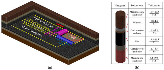
Figure 1.
Layout of working face and geologic histogram. (a) Layout of the 8209 working face; (b) geologic histogram.
To mitigate the tense mining succession relationship, the excavation of the 5209 return air roadway lagged behind the excavation of the 2210 transportation roadway in the mine, and the 5209 return air roadway had already been completed when the 8210 working face was excavated. The size of the 5209 roadway is 5.0 m × 3.9 m. The 5209 roadway experienced severe impacts during the mining of the 8210 working face because of the special mining and excavation succession relationship. As shown in Figure 2, the floor of roadway underwent severe deformation and damage due to the advanced and lateral support pressure formed during the mining. The roadway floor shows asymmetry, indicating that the maximum position of the floor heave is located on the coal pillar side.
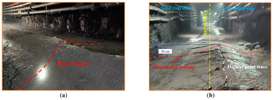
Figure 2.
Failure characteristics of the roadway floor. (a) Floor heave; (b) Asymmetric floor deformation.
3. Monitoring the Floor Deformation
During the mining process of the 8210 working face, the asymmetric floor heave phenomenon is significant in the 5209 return air roadway. In order to specifically know the deformation laws of the floor, monitoring stations of the floor displacement were set up in the 5209 roadway. Figure 3 shows the arrangement of the monitoring stations and measurement points. Station 1 and station 2 are placed 150 m and 50 m away from the working face, respectively, as shown in Figure 3a. The locations of the measurement points at each station are shown in Figure 3b,c. Measurement points A (D), B (E) and C (F) are arranged on the solid coal side, the middle of roadway and the coal pillar side at each station, respectively. The centerline of the roadway height is used as the reference line. The height of the floor from the reference line is measured with a steel ruler. The monitoring ended when the measuring station lied at 150 m of the 8210 working face. Station 1 was monitored for 75 days, with a working face advance distance of 300 m. Station 2 was monitored for 50 days, with a working face advance distance of 200 m.
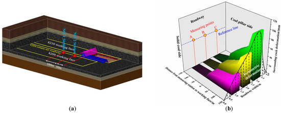
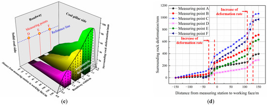
Figure 3.
Layout of measuring stations and deformation curve of roadway floor. (a) Layout of measuring stations; (b) Layout of measurement points and deformation curve of the floor at Station 1; (c) Layout of measurement points and deformation curve of the floor at Station 2; and (d) Summary diagram of floor deformation curves.
The deformation monitoring curve of the 5209 return air roadway floor is shown in Figure 3b–d. The maximum deformation of the roadway floor at Station 1 and Station 2 lies on the coal pillar side (i.e., the positions of measurement points C and F). The roadway floor shows an asymmetric deformation law in that the displacement of the coal pillar side is more than that of the solid coal side. The max. deformation of the floor near the coal pillar side at Station 1 reaches 1064 mm, the max. deformation of the middle floor reaches 713 mm, and the max. deformation of the solid coal side floor reaches 396 mm, as shown in Figure 3d. The three measurement points at Station 1 all experience two sharp increases in the deformation rate. The first time is where the roadway is about 20 m in front of the upper working face, which is subjected to the advanced support pressure of the upper working face. The deformation rate at the three measurement points significantly increases, and the deformation rate of the coal pillar side floor increases from 4.8 mm/m to 7.7 mm/m. The second time is when the upper working face is 120 m in front of Station 1, in which the roadway is subjected to lateral support pressure from the upper working face, resulting in a more severe deformation of the floor. The deformation rate of the coal pillar side grows from 4.9 mm/m to 13.8 mm/m. When the working face is 130 m from Station 1, the deformation rates of the three measurement points tend to ease off. The max. deformation of floor near the coal pillar reaches 969 mm, the max. deformation in the roadway middle reaches 633 mm and the max. deformation of the floor near the solid coal reaches 295 mm, as shown in Figure 3b. There are two sharp increases in the deformation rate at three measurement points. The first time is when the working face is 20 m behind the measuring station, in which the deformation rate on the coal pillar side increases from 3.2 mm/m to 10.3 mm/m. The second time is when the working face is 120 m in front of the measuring station, in which the deformation rate on the coal pillar side increases from 5.5 mm/m to 15.3 mm/m. It is clear that the asymmetric deformation phenomenon of the floor is significant because of the effect of the lateral and advanced support pressures of the upper-section working face. The lateral support pressure has the most influence.
4. Stress Calculation of Surrounding Rock
The deformation features of roadways are closely related to the stress environment. The 5209 return air roadway is affected by multiple mining movements caused by the roadway and the excavation of the 8210 working face, and the stress environment is complex and variable. There is a stress concentration around the roadway after the excavation. Taking a circular roadway within a biaxial isobaric stress field as an example, the stress distribution is calculated using the elastic mechanics method based on the plane strain problem. Figure 4 shows the area where the stress around the roadway is less than the strength of the rock, which is called the elastic zone (C). If the stress is more than the strength of rock, the roadway will undergo plastic deformation, forming a plastic deformation zone (B) with a radius of R. The area where the stress in the plastic zone is less than the original stress is called the fracture zone (A). The area outside the elastic zone is the original stress zone (D) [22].
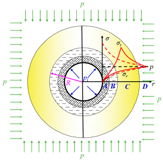
Figure 4.
Surrounding rock zoning for circular roadway excavation.
The tangential stress of the plastic zone can be obtained by the following formula [23]:
In the formula, c represents the rock cohesive strength, with a value of 1.5 MPa; φ represents the internal friction angle of coal with a value of 18°; r is the radius of the studied point within the limit equilibrium zone in m; and r0 is the radius of the roadway, with a value of 2.4 m. According to the famous modified Fenner equation, the radius of the plastic zone is obtained as follows:
In the formula, p is the original stress in MPa. Pi is the support resistance of the roadway, with a value of 0.2 MPa. The tangential stress in the elastic zone can be obtained as follows:
H represents the burial depth of the roadway, which is 415 m. The unit weight of the overlying rock γ is 2500 kN/m3. The following formulas can be obtained through our calculations:
Based on the monitoring results of the roadway floor heave in the previous section, it can be concluded that the lateral support pressure due to the mining of the 8210 working face has a significant impact on the roadway floor heave. Therefore, the following section focuses on analyzing the distribution of the lateral support pressure caused by the 8210 working face. The pressure is determined by the lateral overlying rock structure of the goaf. The main roof rock blocks are difficult to form a stable masonry beam with because of the large mining height. Instead, they form a cantilever beam structure, which can only form a stable hinge structure in higher rock layers. Whether the main roof can form a masonry beam can be determined based on the following formula [24]:
M represents the thickness of the coal seam with a value of 15 m; the coefficient of the collapse and expansion Kp of the collapsed rock block is taken as 1.3; represents the thickness of the immediate roof with a value of 5.4 m; the main roof thickness h is 14.8 m; the periodic weighting step l is taken as 25 m; the load on the overlying rock is q; and the main roof compressive strength is 78.5 MPa. It is calculated that Δ is 13.38, which is greater than 12.85, so a cantilever beam is formed on the main roof, as shown in Figure 5.
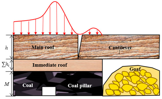
Figure 5.
Overlying rock structure of roadway.
The reason for the lateral support pressure is consistent with that of the leading support pressure, and the form of the lateral support pressure is also similar to that of the leading support pressure, which can be expressed by a simplified exponential function. A model to calculate the lateral support pressure is established using the limit equilibrium theory, as shown in Figure 6 [25,26]. In the figure, P0 represents the support resistance in MPa. x represents the distance from the inspection point to the coal wall in m. 0 − x0 is the plastic zone, x0 − x1 is the elastic zone, and K is the lateral support pressure concentration coefficient. From the plastic zone, a unit is taken, and the force balance in the x-direction is shown as follows [27]:
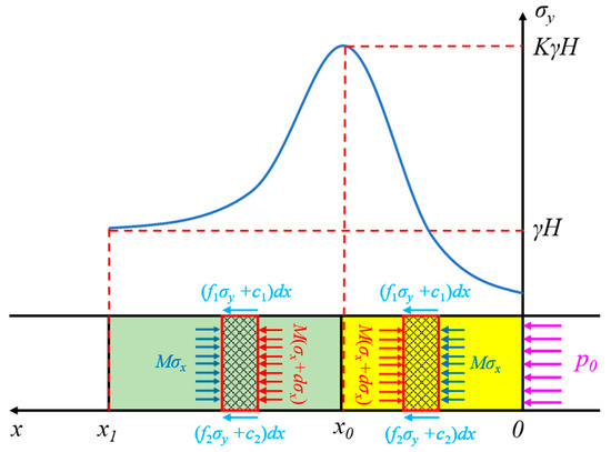
Figure 6.
The mechanical model of the lateral support pressure.
In the formula, σx is the horizontal stress of the coal body. f1 and f2 are the friction coefficients of the bedding plane; and c1 and c2 are the cohesion between the coal seam and the immediate roof and floor interfaces, respectively. We assume that the yield of coal in the plastic zone satisfies the Mohr–Coulomb criterion, i.e.:
In the formula, φ represents the internal friction angle in the coal. Substituting Formula (7) into Formula (6) yields the following:
Considering the boundary conditions, when x equals 0 and σx equals p0, the stress in the y-direction is as follows:
Solving Formula (8) can obtain:
We substitute into Formula (9) to obtain the position of the peak point of the support pressure as follows:
Taking a unit body from the elastic zone, the following can be inferred from the force balance in the x-direction:
In the elastic zone, it satisfies the following conditions: , , λ, which represents the coefficient of the lateral pressure. Considering the boundary conditions, our calculation results are as follows:
We substitute into Formula (12) to obtain the farthest position under the support pressure as follows:
Assuming that the friction coefficient of each layer is equal, the cohesion between the coal seam and the immediate roof and floor interfaces is equal, i.e., MPa. The stress concentration coefficient K is 2.5. The resistance p0 of the coal wall support is 0.2 MPa. λ has a value of 1.3. By incorporating the above formulas, the following can be concluded:
5. Mechanism and Deformation Law of Roadway Floor Heave
The stress characteristics, the size of plastic zone and the deformation of the roadway floor under the roadway excavation and pressure disturbance due to the mining of the upper working face are analyzed by a numerical simulation analysis. The numerical calculation model is shown in Figure 7. A Flac3D numerical calculation model (x × y × z = 540 × 250 × 116 m) is established with a displacement of 0 at the bottom and side boundaries of the model based on the actual geological conditions. The Mohr–Coulomb criterion is adopted for a constitutive relationship. The applied stress on the upper boundary is 8.7 MPa with a lateral pressure coefficient of 1.2. The cross-section of the working face is 220 m × 15 m, and that of the 5209 roadway is 5 m × 4 m. Table 1 shows the mechanical parameters of each rock layer.
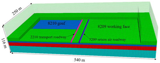
Figure 7.
Numerical calculation model.

Table 1.
Mechanical parameters of each rock layer and coal seam.
5.1. Stress Distribution of Roadway Surrounding Rock
The vertical stress distribution laws of the surrounding rock due to the roadway excavation are shown in Figure 8. The vertical stress of the rock mass on both sides centered on the central axis of the roadway presents a symmetrical distribution pattern. The vertical stress curve is obtained by setting a monitoring line in the roadway. The vertical stress on the right side of the roadway is analyzed as an example: the vertical stress is the lowest at the edge of the roadway. The vertical stress curve grows first and then decreases as it gets farther away from the central axis of the roadway. The vertical stress curve exhibits a single peak distribution pattern. At the position 6 m from the central axis of the roadway, the max. stress is 15.5 MPa, and then the vertical stress is gradually reduced until it approaches the original stress, which is 10.38 MPa. According to the vertical stress calculation formula during the roadway excavation, a theoretical curve is obtained. The vertical stress reaches its peak at a distance of 5.6 m away from the central axis of the roadway, and the max. stress is 15.4 MPa. Then the vertical stress is gradually reduced until it approaches the original stress. The theoretical curve is basically identical to the numerical simulation curve, which validates the correctness of the theoretical calculation.
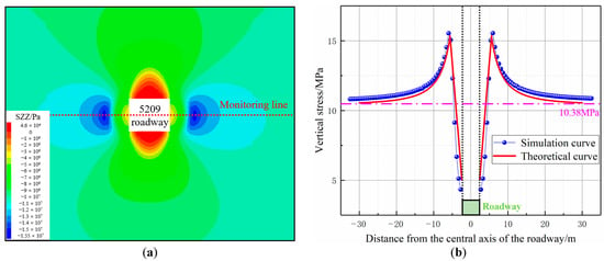
Figure 8.
Vertical stress distribution of roadway excavation. (a) A map of vertical stress; (b) Vertical stress distribution along the monitoring line.
The distribution laws for the lateral vertical stress caused by the 8210 working face are simulated for a situation in which the 5209 roadway is not excavated. Figure 9 shows that the lateral vertical stress first grows and then is reduced with the increasing distance from the goaf side coal wall. A stress core is formed at a distance of 33 m from the coal wall, and the max. stress reaches 27 MPa. The distribution curve of the horizontal vertical stress caused by the upper working face is obtained by arranging a monitoring line in the coal seam. An analysis shows that the vertical stress at the edge of the coal wall in the goaf is the lowest, and the vertical stress curve grows first and then is reduced further away from the goaf. The max. stress is 25.4 MPa at a position 5.5 m from the left of the central axis of the 5209 roadway, and then the stress is gradually reduced until it approaches the original stress with a value of 10.38 MPa. According to the above calculation formula of the lateral abutment pressure, the theoretical curve of the lateral vertical stress in the goaf is obtained. The stress reaches its peak at a position of 6 m on the left side of the central axis of the roadway for which the max. stress is 25.9 MPa, and then the stress is gradually reduced until it approaches the original stress. The theoretical curve is basically identical to the numerical simulation curve, which validates the correctness of our theoretical calculation.
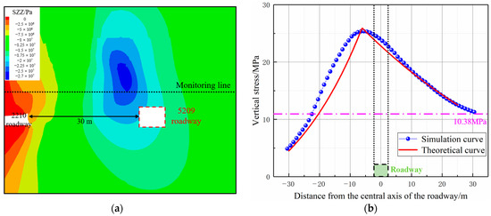
Figure 9.
Vertical stress distribution of 8210 working face excavation. (a) A map of vertical stress; (b) Vertical stress distribution along the monitoring line.
The coupled vertical stress distribution laws under the influence of mining at 120 m behind the working face during the advance of the 8210 working face after the roadway excavation are simulated. Figure 10 shows the stress distribution: the left side of the roadway is a coal pillar, and the right side is solid coal. Stress cores are formed on the roadway both sides. A stress core on the coal pillar side is located at the lower left side of the roadway, while the stress core on the solid coal side is located at the upper right side of the roadway. The max. stress of stress core on the left side is 26 MPa, and the max. stress on the right side is 24 MPa. The coupled stress distribution curve is obtained by setting a monitoring line. The stress at the edges of both sides is the lowest, and the vertical stress curve grows first and then decreases as the distance from the central axis of roadway increases. The max. coupling stress on the left side of the roadway is located 12.5 m from the central axis of the roadway, and the max. stress is 26.9 MPa with a stress concentration coefficient of 2.6. The max. coupling stress on the right side of the roadway is located 11.4 m from the central axis of the roadway, and the max. stress is 19.5 MPa with a stress concentration coefficient of 1.9. Then the vertical stress is gradually reduced until it approaches the original rock stress. The stress curve on both sides of the roadway presents an asymmetric distribution pattern in which the stress of the roadway near the coal pillar is more than the stress near the solid coal. Additionally, the max. stress near the coal pillar is 1.4 times that of near the solid coal.
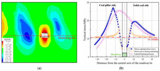
Figure 10.
Vertical stress distribution of 8210 working face mining after roadway excavation (a) A map of vertical stress; (b) Vertical stress distribution along the monitoring line.
5.2. Mechanism of Asymmetric Floor Heave
This article analyzes the reasons for the formation of roadway floor heave based on the slip line theory. After the stress of the floor exceeds its ultimate strength under the influence of mining, the floor will undergo elastic and plastic deformation and failure, forming a plastic zone. The failure zoning of the floor is shown in Figure 11. The plastic zone of the floor consists of three parts: the voluntary stress zone ABM, GHF, the enforced stress zone MEH, MCD, and the transitional stress zone MBC, EFH [28]. The rock in the voluntary stress area is subjected to stress compression in the vertical direction, causing an expansion deformation in the horizontal direction and increasing stress in the horizontal direction, leading to tensile failure in the horizontal direction. The deformation state of the rock is tensile strain, and the deformed rock compresses the rock in the transition stress zone. The rock is in a compressive strain state, resulting in compressive shear compression failure. Continuously compressing the rock in the passive stress area, the rock in the passive stress zone undergoes shear slip deformation. With the continuous disturbance of mining stress, the rock in this area will inevitably move towards the free face of the roadway floor, and the accumulated distortion energy in this area will be released, causing the floor to bulge. Under the mining of the upper working face, the max. value and stress range of the support pressure near the coal pillar of the 5209 roadway are significantly more than those near the solid coal. Therefore, the failure area of the floor caused by support pressure near the coal pillar is inevitably more than that near the solid coal, and the roadway floor will undergo asymmetric failure.
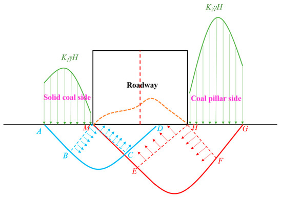
Figure 11.
Schematic diagram of roadway floor failure zoning.
5.3. Distribution Laws of the Plastic Zone in the Roadway
The distribution laws of the plastic zone in the roadway and the excavation of the upper working face are simulated. Figure 12 shows that the plastic zone has a symmetrical distribution along the central axis of the roadway during the roadway excavation, and the depth of the floor plastic zone is 3 m. During the excavation of the upper working face, the plastic zone of the roadway floor 100 m in front of the working face begins to expand to the left, and the depth of the floor plastic zone is 3.5 m. During the mining of the upper working face, the scope of the plastic zone of the roadway 20 m in front of the working face is greatly expanded and interacts with the plastic zone near the coal pillar. The plastic zone of the floor presents an asymmetric distribution pattern in which the scope near the coal pillar is bigger than that near the solid coal, and the depth of the floor plastic zone is 5 m. During the excavation of the upper working face, the scope of the plastic zone 120 m behind the working face is further expanded, and serious deformation occurs in the roadway. Additionally, the plastic zone’s depth increases to 5.5 m.
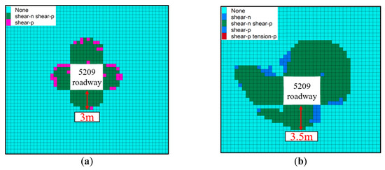
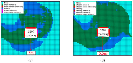
Figure 12.
Plastic zones in different periods. (a) Roadway excavation; (b) 100 m in front of the upper working face; (c) 20 m in front of the upper working face; and (d) 120 m behind the upper working face.
5.4. Displacement Distribution of the Floor
The distribution of the vertical displacement of the floor during the roadway excavation is simulated. The vertical displacement distribution and displacement curves of the floor at different depths (0–4 m) are shown in Figure 13. The vertical displacement of the floor centered on the central axis of the roadway presents a symmetrical distribution after the roadway excavation. The displacement of floor decreases with the increase in the depth; this is the case for the floor on the roadway on both sides. The floor failure of the roadway is the floor heave. The central axis displacement is the largest, and the peak displacement is 49.5 mm. The deformation on both sides shows subsidence, and the max. displacement is 31.6 mm.
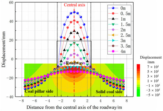
Figure 13.
Curve and cloud of floor displacement during roadway excavation.
The floor displacement distribution at 120 m behind the working face during the mining of the upper working face is simulated. A vertical displacement distribution nephogram and the displacement curves of the floor at different depths (0–4 m) are shown in Figure 14. The displacement of the floor centered on the central axis of the roadway shows an asymmetric form in which the coal pillar side is relatively large under the mining of the upper working face. The displacement of the roadway floor is reduced with the increase in the depth. Floor deformation is manifested as floor heave, and the max. displacement is reached 1 m away from the central axis on the left side of the roadway. The peak displacement is 873 mm. Floor subsidence occurs on both sides of the roadway. The maximum displacement of the floor near the coal pillar is 627 mm, and that near the solid coal is 131 mm.
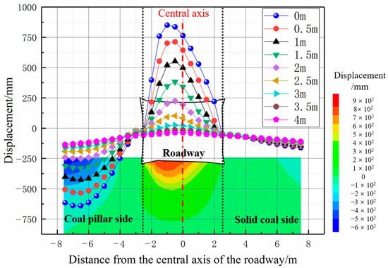
Figure 14.
Curve and cloud of floor displacement during 8210 working face mining after roadway excavation.
6. Control Measures of Roadway Asymmetric Floor Heave
The roof and two sides of the coal body of the roadway have low strength, a poor bearing capacity and insufficient support strength, which lead to the instability of the roof and rock of the two sides and the transfer of stress to the floor under strong mining stress, leading further to floor failure [29,30]. Therefore, our priority in solving floor heave is strengthening the roof and two sides of the roadway, blocking or reducing the stress transfer of the roof and two sides, controlling the stability of the roof and two sides, and then avoiding floor stress concentration. Control methods are implemented to the floor based on the above.
6.1. Strengthening the Support to the Roof and Coal Wall
The instability of the roof will aggravate the failure of the two sides, and stress will be transferred to the two sides, which will indirectly lead to an increase in the supporting stress of the floor and aggravate the appearance of the floor heave. Therefore, controlling the stability of the roof is important for preventing floor heave. In the original support scheme, the strength of an anchor cable support is not enough, which leads to serious roof subsidence near the coal pillar and then causes the formation of a high stress concentration and floor heave at the coal pillar side. Therefore, an asymmetric truss anchor cable is chosen to control the roof’s asymmetric deformation. As shown in Figure 15, the asymmetric truss anchor cable structure is composed of a high-strength anchor cable, reinforced ladder beam and U-bar, with a supporting pallet, a thick gasket and other auxiliary components. The anchor cable on the coal pillar side is linked with a U-bar. It is necessary to ensure that the anchoring section of the anchor cable is located in a stable rock mass deep in the roadway. The structure increases the strength and stiffness required by the supporting system, ensuring the coordinated deformation between the supporting body and surrounding rock [31,32,33].
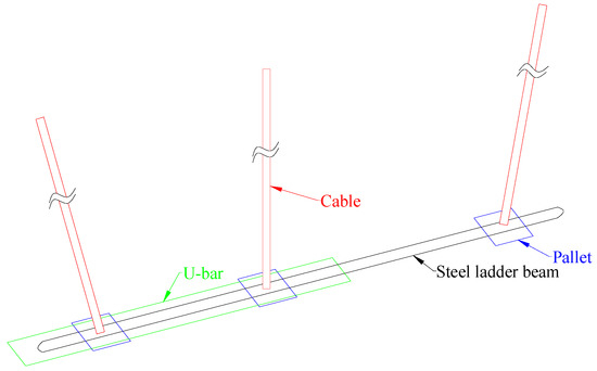
Figure 15.
Asymmetric truss anchor cable structure.
It is important to increase the supporting strength of the two sides, improve their ability to resist deformation, lower the high stress transmitted on both sides and lower the high stress transmitted by the two sides of the floor. Our original support scheme of bolts on the two sides of the roadway would not be able to control the deformation. As shown in Figure 16, it is necessary to match the anchor cable with a high preload force to meet the support stiffness and strength requirements of the supporting system [34,35,36].
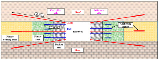
Figure 16.
The support effect of anchor cables.
6.2. Floor Control Measures
Floor leveling is a common treatment method for floor heave, but it does not solve floor heave at its root. For roadways affected by repeated mining, frequent floor leveling is inefficient and uneconomic. A floor anchor cable can connect shallow, low-strength rock strata with deep, high-strength stable rock strata and prevent the sliding deformation of the weak surfaces and the floor heave phenomenon by improving the friction between the floor strata [37]. For the existing roadway floor heave, it is necessary to take floor-leveling measures first to ensure the original roadway section. After floor leveling, an anchor cable support is implemented on the floor and a high-strength concrete layer is laid on the surface to increase the floor’s deformation resistance. The thickness of the concrete layer is 200 mm, with an inner lining of a Φ6 metal mesh. The concrete strength grade is C30. The combination of the above methods is able to efficiently control floor heave.
Our initial scheme to support the roadway is as follows. The roof cables are Φ21.8 mm × 6300 mm prestressed-steel strands, with three pieces in each row. The row spacing is 1800 mm × 1800 mm, the angle between the most lateral anchor cable in the horizontal direction is 60° and the roof anchor cable tray size is 250 mm × 250 mm × 16 mm. The roof bolts are Φ22 mm × 2400 mm screw steels, with six pieces in each row. The row spacing is 900 mm × 900 mm, the angle between the most lateral bolt in the horizontal direction is 75° and the roof anchor bolt’s tray size is 130 mm × 130 mm × 10 mm. The two sides have Φ20 mm × 2000 mm screw steel bolt, with four pieces in each row. The upward and downward angles of the upper- and lower-side bolts are 15°. The row spacing is 1000 mm × 900 mm. The bolt tray size is 130 mm × 130 mm × 10 mm. The roof uses a Φ6 steel wire mesh with a size of 100 × 100 mm. The two sides have a #8 diamond mesh, with a size of 50 mm × 50 mm. The roof bolt support is matched with a 4800 × 280 × 3.75 mm W steel belt, the roof cable support is matched with a 3900 × 330 × 6 mm JW steel belt and the side bolt is matched with a 450 × 280 × 3.75 mm W steel belt. The scheme is shown in Figure 17.
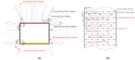
Figure 17.
Supporting scheme of roadway. (a) Front view; (b) Top view.
The roadway reinforcement control scheme is shown in the figure (labeled in red). The asymmetric truss anchor cables for the roof are Φ21.8 mm × 6300 mm steel strands, with four pieces in each row. The angle between the side anchor cable in the horizontal direction is 15°, and the middle one is arranged perpendicular to the roof. The row spacing is 1300 mm + 1700 mm × 1800 mm, and the range between the anchor cables near the coal pillar and coal wall is 800 mm. The bolt tray size is 250 mm × 250 mm × 16 mm. The anchor cables are linked with 3700 mm × 70 mm steel ladder beams. The roadway’s middle and anchor cables at the coal pillar side are linked by a U-bar, with a length of 2200 mm. The size of the steel gasket is 250 mm × 120 mm × 16 mm. The two sides have Φ21.8 mm × 4300 mm screw steel bolts, with three pieces in each row. The upward and downward angles of the upper- and lower-side cables are 75°. The row spacing is 1100 mm × 1800 mm. The cable tray size is 250 mm × 250 mm × 16 mm. The side anchor cable support is matched with a 2600 × 330 × 6 mm JW steel belt. The floor has Φ21.8 mm × 4500 mm screw steel bolts, with two pieces in each row. The angle between the two anchor cables in the horizontal direction is 75°. The row spacing is 5200 mm × 1800 mm. The cable tray size is 150 mm × 150 mm × 12 mm.
7. Engineering Practice
The 5209 roadway was repaired after the mining of the 8210 working face to ensure normal use for the mining of the 8209 working face. The above combined control scheme of “floor leveling + anchor cable support + concrete hardening” was applied to the floor heave treatment in the roadway repair stage. To verify the effectiveness of the asymmetric floor heave control, a surface displacement monitoring station was established in the central position of the roadway alignment (at a mining position of 500 m) to monitor the floor deformation. The layout of the measurement points and the monitoring results are shown in Figure 18. Three measurement points were arranged at this station. The following is an analysis of our monitoring data of the roadway floor displacement: the first stage is the slow deformation stage, in which the deformation rate of the floor slowly increases between 60 m and 130 m in front of the working face; the second stage is the stage of the rapid deformation of the floor, in which the deformation rate rapidly increases between 20 m and 60 m in front of the working face; and the third stage is the stable deformation stage of the floor, in which the deformation rate of the roadway floor decreases and tends to stabilize between 0 m and 20 m in front of working face. The monitoring work ends when the working face pushes past the station position. The maximum floor heave near the coal pillar is 167 mm, the max. floor heave at the central roadway is 113 mm and the max. floor heave near the solid coal is 81 mm. The results show that the floor heave is obviously controlled during the mining of this working face, which proves that the asymmetric control strategy of floor heave can achieve the long-term stabilization of roadways under strong mining.
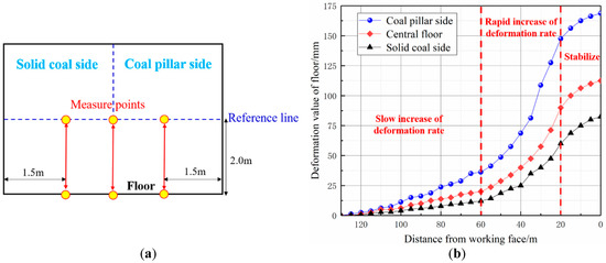
Figure 18.
Layout of measure points and monitoring curve. (a) Layout of measure points; (b) Monitoring curve.
8. Conclusions
- (1)
- The formulas to calculate the horizontal vertical stress of the roadway caused by the excavation and mining of the upper working face are derived separately. The theoretical curve is basically identical to the numerical simulation curve. The vertical stress coupling curve on both sides during the mining of the upper working face is obtained through a numerical simulation.
- (2)
- The cause of the asymmetric floor heave is the uneven distribution of vertical stress on both sides of the floor. The stress concentration coefficient near the coal pillar of the roadway is 2.6, and the stress concentration coefficient near the solid coal is 1.9. The failure area of the floor near the coal pillar is more than that near the solid coal.
- (3)
- Our numerical simulation shows a symmetrical distribution of the displacement curve of the floor during the roadway excavation, with a max. displacement of 49.5 mm. The displacement curve of the floor during the mining of the upper working face is asymmetrical with a max. displacement of 873 mm at a distance of 1 m from the central axis near the coal pillar. The maximum depth of floor failure is 5.5 m.
- (4)
- According to the cooperative control principle of a roof, two sides and a floor, the asymmetric floor heave joint control scheme of “floor leveling + anchor cable support + concrete hardening” is proposed. The floor deformation monitoring results indicate that the max. floor heave at the measurement point near the coal pillar is 167 mm, and the floor heave is effectively controlled.
Author Contributions
Conceptualization, D.W. and F.H.; methodology, Y.Z. (Yajiang Zhang); software, J.S., X.W. and K.T.; formal analysis, J.Z. and F.W.; investigation, P.J.; data curation, Y.W. and B.L.; writing—original draft preparation, D.W.; writing—review and editing, Y.Z. (Yun Zheng) and F.H.; funding acquisition, Y.Z. (Yun Zheng) and F.H. All authors have read and agreed to the published version of the manuscript.
Funding
This work was supported by the National Natural Science Foundation of China (No. 52004286), the National Natural Science Foundation of China (No. 51974317), the Fundamental Research Funds for the Central Universities (2022YJSNY09) and the Fundamental Research Funds for the Central Universities (3142019010).
Data Availability Statement
The data presented in this study are available on request from the corresponding author. The data are not publicly available due to the privacy protection of research achievements.
Conflicts of Interest
The authors declare that they have no known competing financial interests or personal relationships that could have appeared to influence the work reported in this paper.
References
- Liang, M.F.; Hu, C.J.; Yu, R.; Wang, L.X.; Zhao, B.F.; Xu, Z.Y. Optimization of the process parameters of fully mechanized top-coal caving in thick-seam coal using BP neural networks. Sustainability 2022, 14, 1340. [Google Scholar] [CrossRef]
- He, F.L.; Liu, B.Q.; Wang, D.Q.; Chen, D.D.; Wu, Y.H.; Song, L.M.; Ma, X.; Ye, Q.C.; Jiang, Z.S.; Guo, F.F.; et al. Study on stability and control of surrounding rock in the stopping space with fully mechanized top coal caving under goaf. Energies 2022, 15, 8498. [Google Scholar] [CrossRef]
- Wang, D.Q.; He, F.L.; Wu, Y.H.; Xu, X.H.; Zhang, J.L.; Lv, K.; Li, L.; Zhai, W.L.; Song, J.Y. Study on surrounding rock failure mechanism and rational coal pillar width of the gob-side coal roadway under influence of intense dynamic pressure. Energy Sci. Eng. 2023, 1–18. [Google Scholar] [CrossRef]
- Li, Z.X.; Zhang, Y.D.; Ma, Q.; Zheng, Y.; Song, G.Y.; Yan, W.Z.; Zhang, Y.; Hu, L. The floor heave mechanism and control technology of gob-side entry retaining of soft rock floor. Sustainability 2023, 15, 6074. [Google Scholar] [CrossRef]
- Yang, J.; Gao, Y.B.; Liu, S.Q.; Peng, Y.H.; Zhang, H.W. Study on failure mechanism and control techniques of the preparation roadway induced by dynamic mining disturbance. J. Min. Sci. Technol. 2018, 3, 451–460. [Google Scholar]
- Xie, S.R.; Li, H.; Chen, D.D.; Feng, S.H.; Ma, X.; Jiang, Z.S.; Cui, J.Q. New technology of pressure relief control in soft coal roadways with deep, violent mining and large deformation: A key study. Energies 2022, 15, 9208. [Google Scholar] [CrossRef]
- Mo, S.; Tutuk, K.; Saydam, S. Management of floor heave at bulga underground operations—A case study. Int. J. Min. Sci. Technol. 2019, 29, 73–78. [Google Scholar] [CrossRef]
- Mo, S.; Ramandi, H.L.; Oh, J.; Masoumi, H.; Canbulat, I.; Hebblewhite, B.; Saydam, S. A new coal mine floor rating system and its application to assess the potential of floor heave. Int. J. Rock Mech. Min. Sci. 2020, 128, 104241. [Google Scholar] [CrossRef]
- Chen, Y.; Bai, J.B.; Yan, S.; Xu, Y.; Wang, X.Y.; Ma, S. Control mechanism and technique of floor heave with reinforcing solid coal side and floor corner in gob-side coal entry retaining. Int. J. Min. Sci. Technol. 2012, 22, 841–845. [Google Scholar] [CrossRef]
- Indraratna, B.; Nemcik, J.A.; Gale, W.J. Review and interpretation of primary floor failure mechanism at a longwall coal mining face based on numerical analysis. Geotechnique 2000, 50, 547–557. [Google Scholar] [CrossRef]
- Małkowski, P.; Ostrowski, Ł.; Stasica, J. Modeling of Floor Heave in Underground Roadways in Dry and Waterlogged Conditions. Energies 2022, 15, 4340. [Google Scholar] [CrossRef]
- Małkowski, P.; Ostrowski, Ł.; Bednarek, Ł. The effect of selected factors on floor upheaval in roadways—In situ testing. Energies 2020, 13, 5686. [Google Scholar] [CrossRef]
- Sakhno, I.; Liashok, I.; Sakhno, S.; Isaienkov, O. Method for controlling the floor heave in mine roadways of underground coal mines. Min. Miner. Depos. 2022, 16, 1–10. [Google Scholar] [CrossRef]
- Wang, W.J.; Hou, C.J.; Bai, J.B.; Li, X.H. Mechanical deformation analysis and principle of floor heave of roadway driving gob in fully mechanized sub—Level caving face. Rock Soil Mech. 2001, 2001, 319–322. [Google Scholar]
- Jiang, Y.D.; Zhao, Y.X.; Liu, W.G.; Li, Q. Research on floor heave of roadway in deep mining. Chin. J. Rock Mech. Eng. 2004, 2004, 2396–2401. [Google Scholar]
- He, M.C.; Zhang, G.F.; Wang, G.L.; Xu, Y.L.; Wu, C.Z.; Tang, Q.D. Research on mechanism and application to floor heave control of deep gateway. Chin. J. Rock Mech. Eng. 2009, 28, 2593–2598. [Google Scholar]
- Bai, J.B.; Li, W.F.; Wang, X.Y.; Xu, Y.; Huo, L.J. Mechanism of floor heave and control technology of roadway induced by mining. J. Min. Saf. Eng. 2011, 28, 1–5. [Google Scholar]
- Chen, S.Y.; Song, C.S.; Guo, Z.B.; Wang, J.; Wang, Y. Asymmetric deformation mechanical mechanism and control countermeasure for deep roadway affected by mining. J. China Coal Soc. 2016, 41, 246–254. [Google Scholar]
- Jia, H.S.; Wang, L.Y.; Liu, S.W.; Peng, B.; Zhang, W.G.; Fan, K. Mechanism and control strategy of asymmetrical floor heave of coal pillar roadway in fully mechanized caving face. J. China Coal Soc. 2019, 44, 1030–1040. [Google Scholar]
- Yang, R.S.; Zhu, Y.; Li, Y.L.; Li, W.Y. Floor heave mechanism and control measures of layered floor in weakly cemented soft rock roadway. J. Min. Saf. Eng. 2020, 37, 443–450. [Google Scholar]
- Wang, Z.Q.; Wang, P.; Lv, W.Y.; Shi, L.; Su, Z.H.; Wu, C.; Yu, F. Mechanism and control of asymmetric floor heave in gob-side entry. J. Min. Saf. Eng. 2021, 38, 215–226. [Google Scholar]
- Jiang, B.S.; Zhang, Q.; He, Y.N.; Han, L.J. Elastoplastic analysis of cracked surrounding rocks in deep circular openings. Chin. J. Rock Mech. Eng. 2007, 184, 982–986. [Google Scholar]
- Pan, Y.; Wang, Z.Q. Elasto-plastic analysis on surrounding rock of circular chamber based on strain nonlinear softening. Chin. J. Rock Mech. Eng. 2005, 2005, 915–920. [Google Scholar]
- Xu, X.H.; He, F.L.; Li, X.B.; He, W.R. Research on mechanism and control of asymmetric deformation of gob side coal roadway with fully mechanized caving mining. Eng. Failure Anal. 2021, 120, 105097. [Google Scholar] [CrossRef]
- Wang, Z.Q.; Wu, C.; Shi, L.; Su, Z.H.; Wang, P.; Huang, X. Analysis of surrounding rock stress and plastic zone of two-way unequal pressure circular roadway based on complex variable theory. J. China Coal Soc. 2019, 44, 419–429. [Google Scholar]
- Vu, T.T. Solutions to prevent face spall and roof falling in fully mechanized longwall at underground mines, Vietnam. Min. Miner. Depos. 2022, 16, 127–134. [Google Scholar] [CrossRef]
- Chang, J.C.; Xie, G.X.; Zhang, X.H. Analysis of rib spalling mechanism of fully-mechanized top-coal caving face with great mining height in extra-thick coal seam. Rock Soil Mech. 2015, 36, 803–808. [Google Scholar]
- Xu, X.H.; He, F.L.; Li, X.B.; Lv, K.; He, C.X.; Li, L. Roadway impact mechanism and optimization design under coal pillar disturbance in large mining height working face. J. Min. Saf. Eng. 2021, 38, 547–555. [Google Scholar]
- Lai, X.P.; Xu, H.C.; Shan, P.F.; Kang, Y.L.; Wang, Z.Y.; Wu, X. Research on mechanism and control of floor heave of mining-influenced roadway in top coal caving working face. Energies 2020, 13, 381. [Google Scholar] [CrossRef]
- Zhou, X.M.; Wang, S.; Li, X.L.; Meng, J.J.; Li, Z.; Zhang, L.H.; Pu, D.D.; Wang, L.K. Research on theory and technology of floor heave control in semicoal rock roadway: Taking longhu coal mine in Qitaihe mining area as an Example. Lithosphere 2022, 2022, 3810988. [Google Scholar] [CrossRef]
- He, F.L.; Xu, X.H.; Qin, B.B.; Li, L.; Lv, K.; Li, X.B. Study on deformation mechanism and control technology of surrounding rock during reuse of gob side entry retaining by roof pre-splitting. Eng. Failure Anal. 2022, 137, 106271. [Google Scholar] [CrossRef]
- Xie, S.R.; Pan, H. Control mechanism and application of double span truss anchor cable in long span coal roadway. J. Min. Sci. Technol. 2018, 3, 148–155. [Google Scholar]
- Zhang, G.C.; He, F.L. Asymmetric failure and control measures of large cross-section entry roof with strong mining disturbance and fully-mechanized caving mining. Chin. J. Rock Mech. Eng. 2016, 35, 806–818. [Google Scholar]
- Chen, D.D.; Guo, F.F.; Li, Z.J.; Ma, X.; Xie, S.R.; Wu, Y.Y.; Wang, Z.Q. Study on the Influence and Control of Stress Direction Deflection and Partial-Stress Boosting of Main Roadways Surrounding Rock and under the Influence of Multi-Seam Mining. Energies 2022, 15, 8257. [Google Scholar] [CrossRef]
- Sun, X.M.; Zhang, Y.; He, M.C.; Yang, J.K. Research of high pre-stress NPR support technology in deep shaft roadway Engineering. J. Min. Sci. Technol. 2023, 8, 50–65. [Google Scholar]
- Xie, S.R.; Wu, Y.Y.; Guo, F.F.; Zou, H.; Chen, D.D.; Zhang, X.; Ma, X.; Liu, R.P.; Wu, C.W. Application of Pre-Splitting and Roof-Cutting Control Technology in Coal Mining: A Review of Technology. Energies 2022, 15, 6489. [Google Scholar] [CrossRef]
- Zhao, Y.Q.; He, F.L.; Xie, F.X.; Wu, J.K.; Liu, B.Q. Study on comprehensive evaluation of surrounding rock stability grade and repair control technology of gob side entry retaining. J. Min. Sci. Technol. 2017, 2, 550–558. [Google Scholar]
Disclaimer/Publisher’s Note: The statements, opinions and data contained in all publications are solely those of the individual author(s) and contributor(s) and not of MDPI and/or the editor(s). MDPI and/or the editor(s) disclaim responsibility for any injury to people or property resulting from any ideas, methods, instructions or products referred to in the content. |
© 2023 by the authors. Licensee MDPI, Basel, Switzerland. This article is an open access article distributed under the terms and conditions of the Creative Commons Attribution (CC BY) license (https://creativecommons.org/licenses/by/4.0/).