1. Introduction
Due to the modular design, high power quality, and DC fault clearance capability, the modular multilevel converter has a wide application prospect in DC transmission and distribution systems [
1,
2]. At present, sub-/super-synchronous oscillation [
3,
4,
5] and mid-/high-frequency resonance [
6,
7] occur frequently in MMC interconnected systems. Impedance-based analysis is an important method to study the system’s stability. Equivalent impedance modeling is carried out for each subsystem, and the stability of the system under the effect of small disturbances at the steady-state operating point is analyzed according to the linear system stability criteria.
Existing studies have shown that the control system significantly impacts the frequency characteristics of MMC impedance. The MMC arms contain a large number of switching devices, and the cascade structure of submodules causes complex harmonic dynamics [
8,
9]. Additional control requirements for capacitor voltage balance among submodules and circulating current suppression in the arms bring new challenges to the impedance modeling of MMC. The negative damping effect in the frequency characteristics of MMC impedance will be caused by the unreasonable design of control parameters, and resonance instability occurs when the control system interacts with the AC/DC system. Modeling precision determines the accuracy of the stability analysis results of the system, and the detailed impedance modeling method of MMC under the action of multiple controllers has become a research hotspot. Compared to the
dq frame impedance, the sequence impedance model considering multiple frequency harmonics has practical physical significance in the three-phase stationary coordinate system. The accuracy of the model can be verified directly through impedance frequency scanning, which has become the mainstream scheme of MMC impedance modeling [
10].
Previously, the stability analysis based on the MMC sequence impedance model mainly focused on high-voltage and large-capacity systems. As the basis of modeling, the continuous model of MMC assumes that the capacitor voltage fluctuation of each submodule inside the arms remains consistent, and adopts the balance strategy of nearest level modulation based on capacitor voltage sorting. The influence of capacitor voltage harmonics has not been considered during the actual process of control modeling [
11,
12,
13], and it is uncertain whether they have any effect on impedance characteristics. In medium- or low-voltage DC systems, the number of MMC submodules is small, and the capacitor voltage fluctuation range increases. Meanwhile, the typical architecture, which combined carrier phase-shift pulse width modulation (CPS-PWM) and the controlled modulation wave for each submodule, is generally used to maintain capacitor voltage balance. Currently, there is no analysis of the influence of submodule capacitor voltage balance control on the impedance characteristics of MMC in different frequency bands.
In
Table 1, reference [
14] first proposed the sequence impedance model of MMC, which is recognized as an effective method to analyze the practical resonance instability caused by control interaction. Its theoretical basis is harmonic linearization, which has been used in the stability analysis of converter interconnection systems, such as wind turbines, photovoltaic, DC grids, etc. [
15,
16,
17], and further extended to the multi-harmonic linearization. All variables in the developed model are represented by the matrix in the frequency domain. Since the bandwidth of the outer loop power control is significantly lower than that of the inner loop current control, this paper does not consider the influence of the outer loop power control on the impedance characteristics of MMC. The voltage feedforward commonly used in the inner loop current control is also neglected. Reference [
18] studied the MMC sequence impedance modeling method of single star structure applied to wind power grid-connected STATCOM, given the influence of submodule capacitor voltage control on modulation waves. Reference [
19] analyzed the impact of different control parameters on the impedance characteristics of MMC. Based on the complete control structure, references [
20,
21] established the AC/DC-side impedance model of MMC respectively, including the voltage feedforward control during control modeling. In the process of coordinate transformation, only the effect of the disturbance voltage on the small-signal harmonics of insertion indexes is modeled, whereas the small-signal harmonic response generated by the steady-state component of phase voltage and the PLL output disturbance is neglected [
22,
23].
Consequently, there is a lack of suitable impedance modeling methods for MMC over a wide frequency range. In this paper, taking the constant power control MMC as an example, the influence of submodule capacitor voltage control and voltage feedforward control on impedance characteristics is considered. Firstly, an improved wideband impedance model is established, which includes power control, current control, PLL, CCSC, capacitor voltage balance control, and voltage feedforward control. Secondly, the accuracy of the wideband impedance modeling method for MMC is demonstrated by comparing the impedance measurement in a real-time digital simulation model and impedance modeling calculation results. Accordingly, in different frequency ranges, the study investigates the effects of various control parameters on the positive- and negative-sequence impedance characteristics of MMC. Finally, a simulation model of MMC connected to a weak grid is established to analyze the high-frequency resonance mechanism caused by unreasonable control parameter design. The MMC is connected to the weak power grid with SCR = 3 corresponding to an equivalent series inductance of 7.66 mH. The wideband impedance and conventional impedance response results under different PLL control parameters are compared, and the necessity of wideband impedance modeling for MMC in system resonance analysis is verified.
2. Power Stage Model
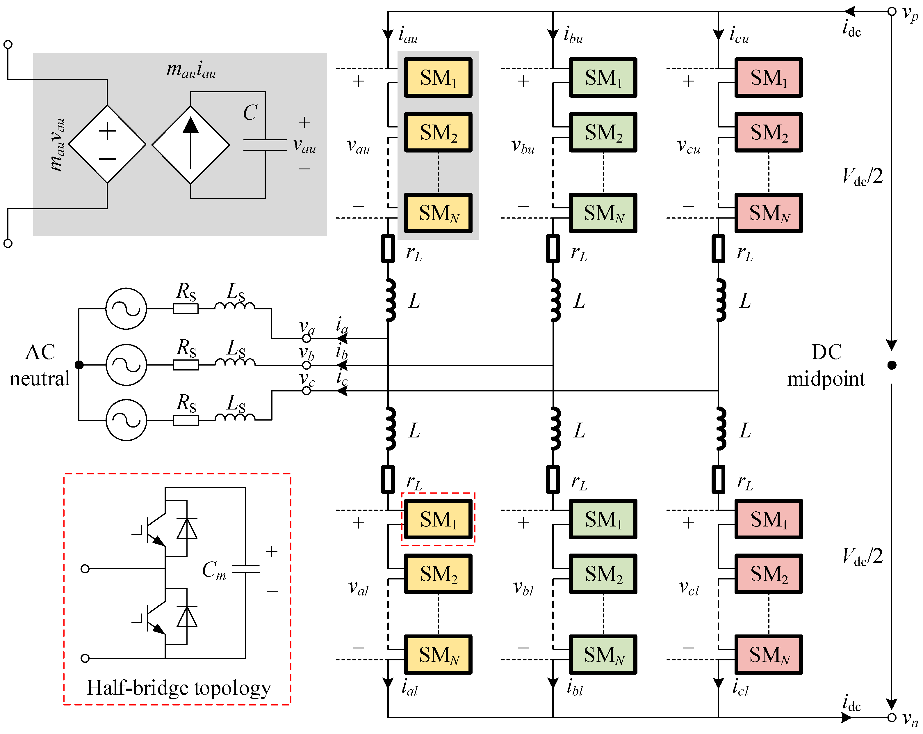
Figure 1 shows the main circuit topology and continuous model of MMC. The sequence impedance modeling is based on the averaged model of MMC [
24]. Accordingly, the discontinuous characteristic induced by the submodule device switching operation is eliminated. All submodule capacitor voltages are assumed to be equal in one arm. Note that this does not mean that the capacitor voltage has no harmonics or remains unchanged. The submodule capacitor voltage balance control output acts directly on the modulating wave and its influence on the impedance characteristics of the converter needs to be considered in the control modeling.
In
Figure 1, each arm consists of
N cascaded submodules using half-bridge topology, and the arm inductor
L with equivalent resistance
rL connected in series. The capacitance of the submodule capacitor is represented by
Cm, both upper and lower arms form a phase leg. Two subscripts indicate three phases (
a,
b, and
c) and two arms (
u for the upper and
l for the lower arm) separately. In the upper arm of phase
a, defining that
mau is the insertion index,
vau signifies the sum of submodule capacitor voltages,
iau is the arm current, and the equivalent capacitance of all submodules capacitor
C =
Cm/
N. By the assumption of the averaged model, MMC has been converted to a continuous system, in which the internal dynamics of MMC can be described accurately and efficiently.
A sinusoidal disturbance voltage is superimposed on the AC side to calculate the phase current response at the corresponding frequency. Without loss of generality, there is a disturbance voltage
vp at frequency
fp in phase
a.
Assuming that
Vdc remains constant,
vm represents the zero-sequence voltage from the midpoint of the DC bus to the AC neutral,
vp =
Vdc/2 +
vm,
vn =
Vdc/2 +
vm, and the linearized model of the upper arm of phase
a can be expressed in the frequency domain.
where
vu,
mu, and
iu are the steady-state harmonic vectors of the corresponding variables. The following vectors are developed in the frequency domain to express the small-signal response of
iau,
vau,
mau, and
vap, and subsequently canceled the subscript of phase
a.
At small-signal harmonic frequencies,
Zl and
Yc represent the diagonal matrix of the impedance of the arm inductor and the admittance of the equivalent capacitor in the arm.
Under the injection of positive-/negative-sequence perturbation voltage, the phase and sequence relationships, among the small-signal harmonics for the variables in Equation (4), can be determined through the following equations.
According to the symmetry characteristics, the small-signal dynamics of MMC can be presented by a single arm. To obtain an independent small-signal model of the arm, it is necessary to eliminate
vm in Equation (2), which can be expressed as
From the above equation,
vm can be eliminated by canceling the ZS/DM harmonics in the arm voltage. The steady-state harmonic vectors
vu,
mu, and
iu are defined as Toeplitz matrices
V,
M, and
I. Therefore, the convolution in the small-signal model is transformed into matrix multiplication. Bringing Equation (9) into Equation (2) and neglecting the subscript of the upper arm, we obtain analytical expressions of the small-signal model of MMC.
where
Yl is the inverse matrix of
Zl, in which the corresponding elements that are multiplied by the ZS/DM components in other variables are equal to zero.
3. Detailed Control Modeling of MMC
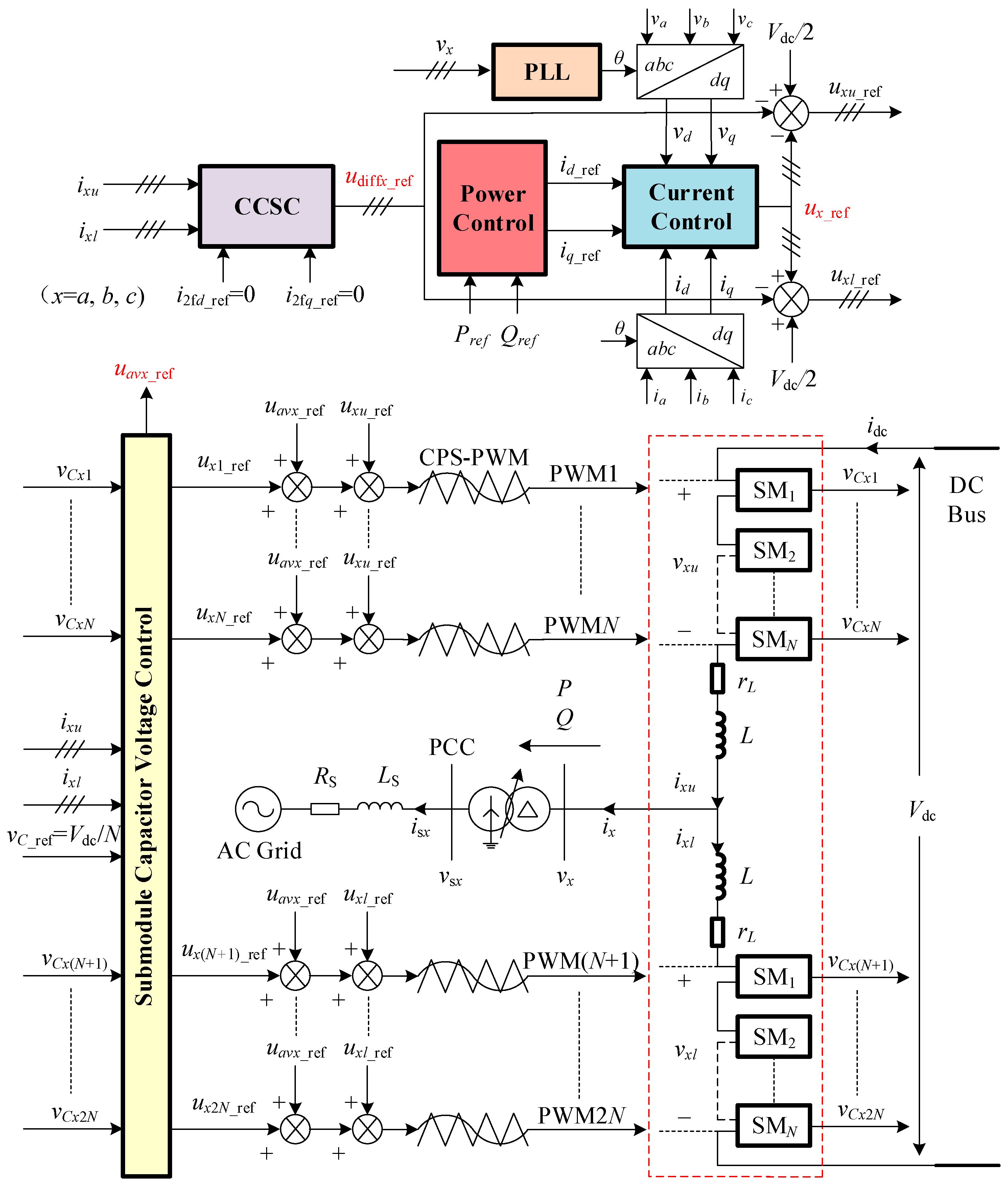
The control system structure of MMC is illustrated in
Figure 2. Detailed control modeling under the perturbation voltage is carried out to obtain the small-signal harmonics response of insertion index
, which can be represented by power stage model variables
,
, and
. Substitute
to the Equations (10) and (11), intermediate variables
and
are eliminated. Consequently, by extracting corresponding elements in the coefficient matrix from the arm current
to the AC perturbation voltage
, the AC-side sequence impedance model of MMC can be obtained.
Considering 4th harmonics in the process of modeling, all the coefficient matrices have a dimension of 9. Among them,
Q includes
Qi,
Qc,
QPQ, and
Qai, which indicates the influence of small-signal harmonic of the arm current on the insertion index through phase current control, CCSC, power control, and submodule capacitor voltage control (circulating current inner loop).
E represents the influence of the small-signal harmonics of the arm equivalent capacitor voltage on the insertion index through the submodule capacitor voltage control (average capacitor voltage outer loop).
Pf and
PPQ represent the influence of the perturbation voltage on the insertion index through voltage feedforward control and power control. Simultaneously, when the steady-state components of phase current and phase voltage transformed from
abc frame to
dq frame, and the output of current control in the
dq frame converted to
abc frame, the small-signal harmonics caused by the perturbation voltage in the output transformation angle of PLL impose effects on the insertion index. The composition of
P involves the four matrices mentioned above.
Typical PI regulators are utilized in each control function. The elements in the coefficient matrix are determined by the specific control parameters and structure.
Figure 2 indicates the control signal on the upper arm of phase
a, described in the frequency domain:
3.1. Phase Current Control
Disregarding phase angle perturbations in the output of the PLL, the modeling of the phase current controller in the frequency domain is as follows. In
Figure 3, the power control output
id_ref and
iq_ref described in
Section 3.4 are references of phase current control in the
dq rotating reference frame. Moreover, the AC terminal voltages
vd and
vq are superimposed with phase current control output in
dq frame, respectively. After
dq/
abc transformation using the steady-state phase angle of the fundamental frequency,
ud_ref and
uq_ref are converted to reference voltages
ux_ref in three-phase.
Under PS/NS voltage perturbation, the elements
/
in the coefficient matrix
Qi can be expressed as Equations (16) and (17).
Of which, Km = −1/Vdc, mod(k + 1, 2) is employed to select DM components, |mod(k + 1, 3)| is used to eliminate ZS harmonics, mod(k + 1, 3) provides sequence relationships for the small-signal harmonics of the arm current, jKid and Hi(s) represent the decoupling gain and transfer function (dq frame) of the current control.
Notably, the phase current control only responds to the DM harmonics in the arm current, and the modeling process does not account for the influence of voltage feedforward control on the modulation wave
udiffx_ref and the insertion index. The inclusion of the voltage feedforward control considering the impact of voltage perturbation and PLL will be detailed in
Section 3.5.
3.2. Circulating Current Suppression Control
The dominant component in the circulating current is the second harmonic, and the controller is modeled in the frequency domain as follows. In
Figure 4, the CCSC only reacts to the CM components in the arm current. The three-phase circulating currents
icirx = 0.5(
ixu +
ixl) are transformed into
i2fd and
i2fq by a phase angle rotating at the second-harmonic frequency. The reference currents
i2fd_ref and
i2fq_ref are set to 0. After
dq/
abc transformation,
udiffd_ref and
udiffq_ref are converted to reference voltages
udiffx_ref in three-phase.
Under PS/NS voltage perturbation, the elements of the CCSC
/
can be expressed as Equations (19) and (20),
jKcd and
Hci(
s) represent the decoupling gain and transfer function in
dq frame.
3.3. Submodule Capacitor Voltage Control
In high-voltage and large-capacity MMC systems, the number of submodules typically ranges from tens to hundreds, therefore, nearest level modulation (NLM) and sorting-based submodule capacitor voltage balancing control are the most commonly used. The harmonics of the arm equivalent capacitor voltage do not directly affect the control signals. Most sequence impedance modeling studies neglected the influence of capacitor voltage balancing control. CPS-PWM is widely utilized in low-voltage MMC, which involves a smaller number of submodules. Reference [
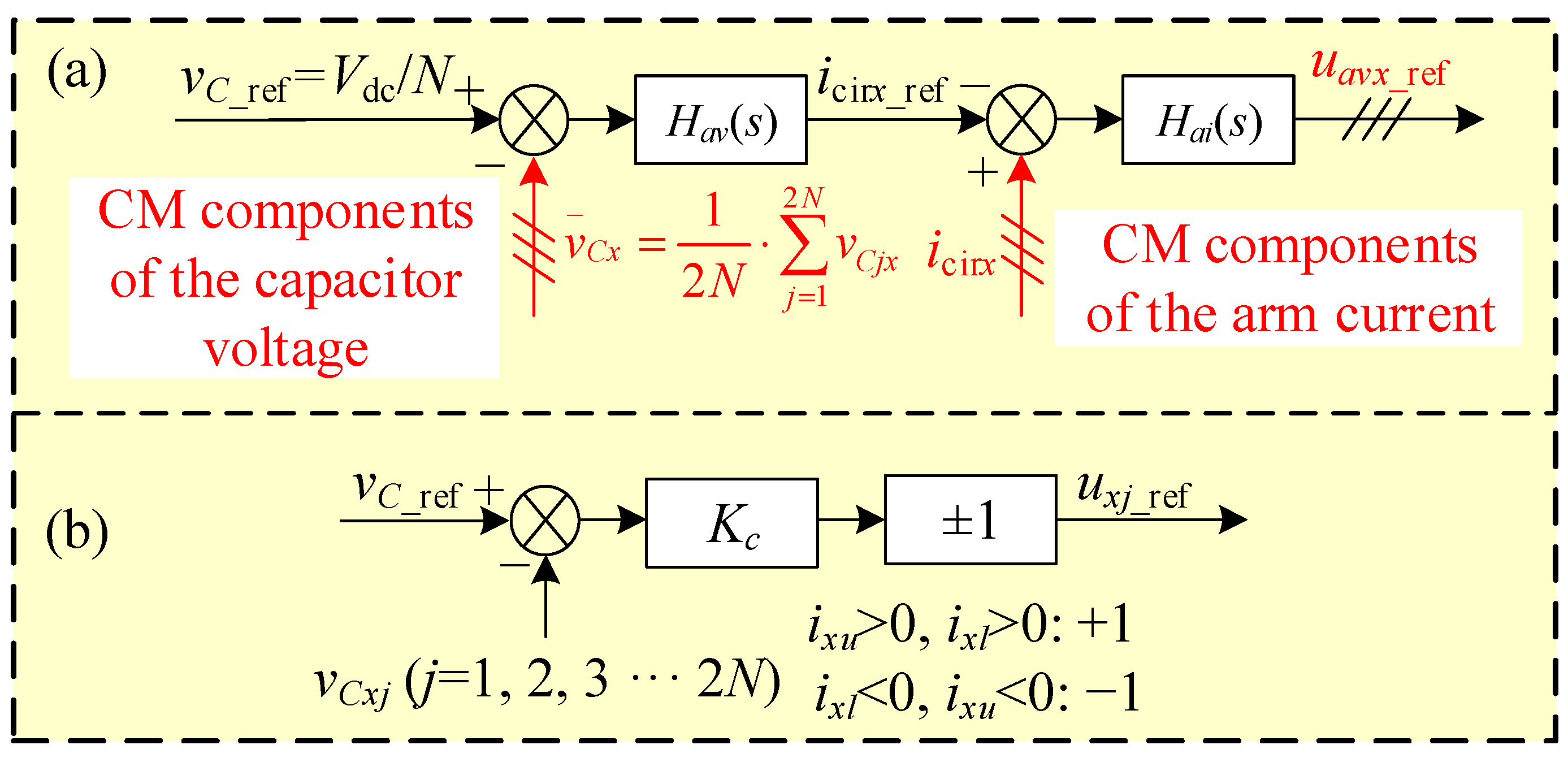
25] proposed a capacitor voltage balancing control method corresponding to CPS-PWM, consisting of two levels: averaging control and balancing control. As shown in
Figure 5, in each phase leg,
vCxj (
j = 1, 2, 3 … 2
N) represent the submodule capacitor voltages. Averaging control compares the average value of the sum of capacitor voltages
with a reference value
vC_ref, and the output
icirx_ref are references of circulating currents in three-phase. Furtherly, the output of the circulating current control
uavx_ref together with
ux_ref and
udiffx_ref form the three-phase modulation wave. Balancing control compares
vCxj with
vC_ref and adjusts the switching time of each submodule separately by
uxj_ref, ±1 determines the polarity of
uxj_ref according to the direction of upper/lower arm currents. Based on the assumption that submodule capacitor voltages remain consistent in the same arm, the influence of capacitor voltage balancing control is disregarded.
Modeling for the submodule capacitor voltage control, the sum of 2
N submodule capacitor voltages in one phase eliminates the DM components. Taking the upper arm of phase a as an example, the average capacitor voltage outer loop only reacts on the CM components in
vau/
N, and the phase a circulating current involves the CM components in
iau. The coefficient matrices
Eav and
Qai are represented as follows:
In
Figure 5, each control function reacts directly in the phase domain, the CM components are controlled by a linear compensator
Hav(
s) and
Hai(
s). Under PS/NS perturbation voltage, the elements of the coefficient matrices have the same analytic expression.
3.4. Power Control
Figure 6 illustrates the block diagram of the power control.
HPQ(
s) represents the transfer function of the corresponding PI regulator. The instantaneous active and reactive power are commonly calculated as follows:
At frequency
fp, the arm currents (PS/NS) and the perturbation voltages (PS/NS) are subjected to the power control, which can be modeled in the frequency domain as
In which and V1 denote the fundamental component of the phase a steady-state current and voltage, respectively, QPQ and PPQ have only one nonzero element, while the remaining elements are zero.
3.5. PLL and Voltage Feedforward Control
The coefficient matrix P in Equation (13) establishes the small-signal relationship between the arm insertion index and the voltage perturbation on the AC side of MMC, covering the following three aspects:
Coefficient matrix PPQ corresponds to power control outer loop;
Coefficient matrix Pf corresponds to AC voltage feedforward in phase current control. After abc/dq and dq/abc transformation using the steady-state phase angle of the fundamental frequency, the AC terminal perturbation voltage of MMC is added to the insertion index directly;
Phase angle disturbance in the output of the PLL caused by voltage perturbation. There are three parts of harmonic response superimposed on the output of the phase current control: (1) the fundamental component of the AC-side voltage converted through abc/dq transformation (perturbation phase angle) and dq/abc transformation (steady-state phase angle); (2) the harmonic transfer process of arm current with current control is similar to (1); (3) the steady-state DC component control output in dq frame subjected to dq/abc transformation (perturbation phase angle); corresponding to coefficient matrices Pu, Pi, and Pm, respectively. During steady-state operation, the harmonic content of the circulating current is close to zero. Therefore, the steady-state DC output of CCSC in the dq frame is relatively small, and the impact of PLL dynamics on the arm insertion index caused by CCSC can be neglected.
This paper investigates the operation of the power grid under three-phase symmetrical balanced conditions. The typical PLL control structure is shown in
Figure 7.
HPLL(
s) represents the transfer function of the corresponding PI regulator, and
ω0 is equivalent to the fundamental frequency. The AC terminal three-phase voltages
vabc are transformed into
vd and
vq by the control output
θ of PLL.
The actual PLL output
θ consists of two parts: a steady-state phase angle 2
πf1t corresponding to the fundamental frequency grid voltage without any disturbances, and a small-signal term caused by voltage perturbation, which can be expressed as
Frequency-domain modeling of phase angle disturbances are expressed as
To quantitatively analyze the harmonics caused by phase angle disturbance in PLL, an additional definition of the steady-state fundamental component of the output reference in phase current control
is required. The coefficient matrix related to the PLL and voltage feedforward is summarized as
PPF in this section. Under the impact of PS/NS voltage perturbation, the elements in
PPF are shown in Equation (33), while the remaining elements are zero.
4. Wideband Impedance Characteristics of MMC
4.1. Detailed Wideband Impedance Model of MMC
After substituting the control model derived in the previous section into Equations (10) and (11), the admittance matrix from the arm current to the AC-side perturbation voltages can be expressed as
The phase current at a frequency of
fp is twice the arm current, and the MMC has an input impedance at
fp of
Y(
n + 1,
n + 1) denotes the (
n + 1,
n + 1)th element of
Y. By setting the matrices
Q,
E, and
P to zero in Equation (34), we obtain the admittance matrix of MMC under open-loop control.
4.2. Verification of the Impedance Model
We compare the impedance measurement simulation and programming calculation results of the detailed MMC circuit to validate the accuracy of the proposed modeling approach. The detailed parameters of the MMC are provided in
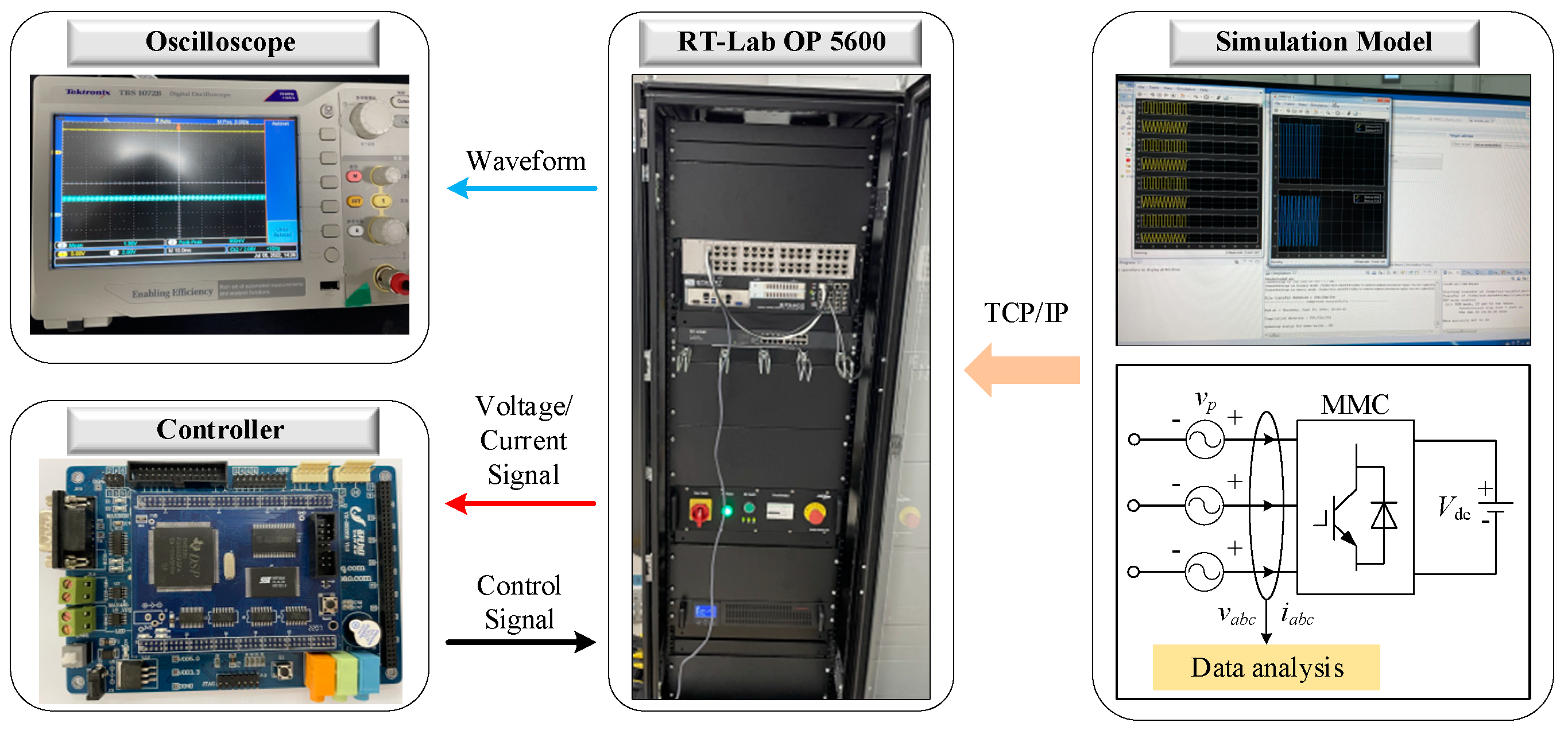
Table 2. Based on the RT-Lab real-time digital simulator OP 5600, an MMC impedance frequency scanning platform was established. The impedance measurement principle is depicted in
Figure 8.
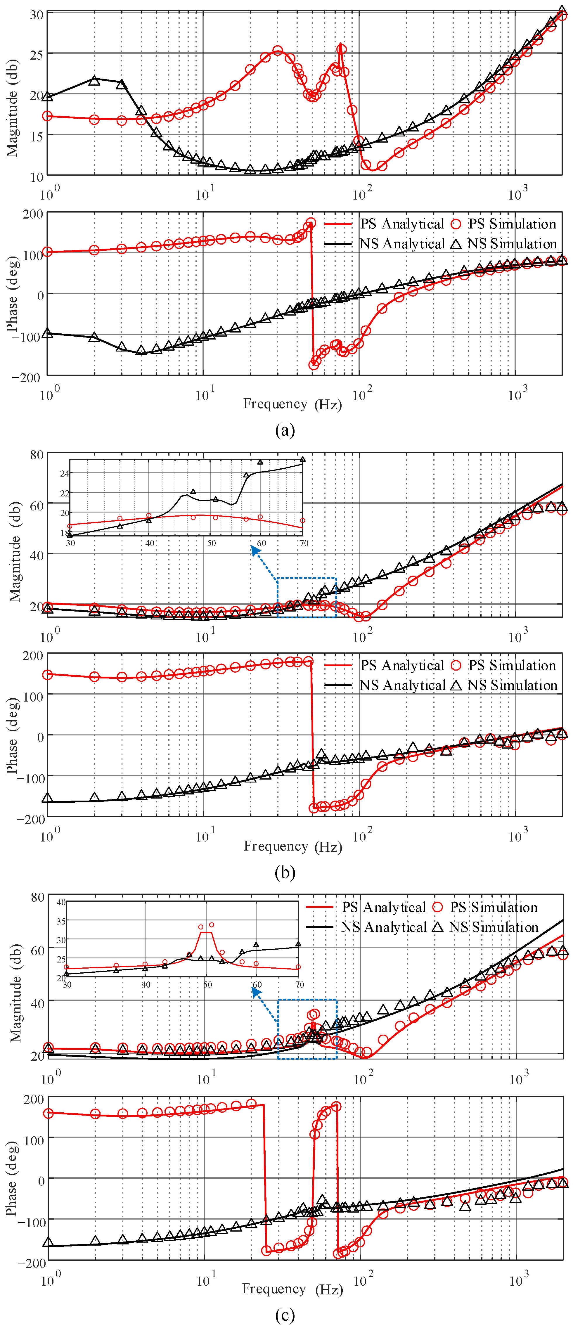
Figure 9 illustrates the impedance response, with the red and black curves representing the calculated positive- and negative-sequence impedance results, respectively. The impedance measurement results are shown as dashed lines of the same color. In
Figure 9a, there is virtually no discrepancy on impedance responses between the analytical and simulation models of MMC. In
Figure 9b,c, at frequencies above 1000 Hz, the maximum error between the analytical and simulation models on magnitude and phase responses is less than 5 dB, 10 deg. The impedance scanning results may exhibit errors at higher frequencies due to constraints imposed by simulation hardware conditions. Scanning the impedance near a resonance frequency is also numerically difficult and prone to errors, which, for example, is responsible for the mismatch at 50 Hz in the positive-sequence impedance response in
Figure 9c. Different control loops will be integrated gradually to validate the control modeling method proposed in
Section 3: (1) phase current control, CCSC, and PLL; (2) Voltage feedforward in phase current control and submodule capacitor voltage control; (3) power control. In phase current control, the
d-axis current reference is set to the corresponding value when the MMC delivers 30 kW active power, while the
q-axis current reference is set to zero.
Figure 9a shows the phase current control (without voltage feedforward) and CCSC implemented with the actual PLL. The impact of perturbation voltage on MMC impedance characteristics primarily exhibits a symmetric frequency coupling behavior around the fundamental frequency, which is characterized by impedance magnitudes being equal at the coupling frequency (
fp and 100−
fp), and the phase exhibits symmetry around zero degrees. Within the sub-/super-synchronous frequency range, the positive- and negative-sequence impedances of the MMC exhibit negative damping characteristics (with a negative real part of the impedance when the phase exceeds ±90°). When the positive- and negative-sequence input impedances of the MMC are equal in magnitude to the impedance of the weak grid system, and the phase difference between them exceeds 180°, negative damping characteristics will lead to resonance instability.
Figure 9b incorporates AC terminal voltage feedforward into the phase current control and takes into account the impact of submodule capacitor voltage control. In the high-frequency range, a significant increase in the impedance magnitude of MMC is observed, accompanied by a transition of phase angles of the positive- and negative-sequence impedances from inductive to capacitive. In the analysis of high-frequency resonance problems, neglecting voltage feedforward may lead to significant errors. With limited influence on other frequency ranges, the influence of submodule capacitor voltage control on converter impedance is concentrated in the low-frequency range.
Figure 9c represents the impedance characteristics of the MMC including power outer loop control. The bandwidth of the power control is much smaller than that of the current control and changes the phase of the positive-sequence impedance of the MMC in the mid- and lowfrequency range. The aforementioned analysis validates the accuracy of the detailed wideband impedance modeling method and provides a model basis for the study of resonant problems in interconnected systems.
4.3. Influence of Control Parameters on Impedance Characteristics
The MMC control system consists of multiple control functions, which achieve stable operation of the converter with different control objectives. The controller bandwidth is distributed in a frequency range of several Hz to several hundred Hz. In this section, we investigate the effects of varying control parameters on the impedance characteristics of different frequency ranges and the resonance instability of the MMC system. The impedance modeling method proposed in this paper is employed to compute the impedance response of the MMC under different control parameters.
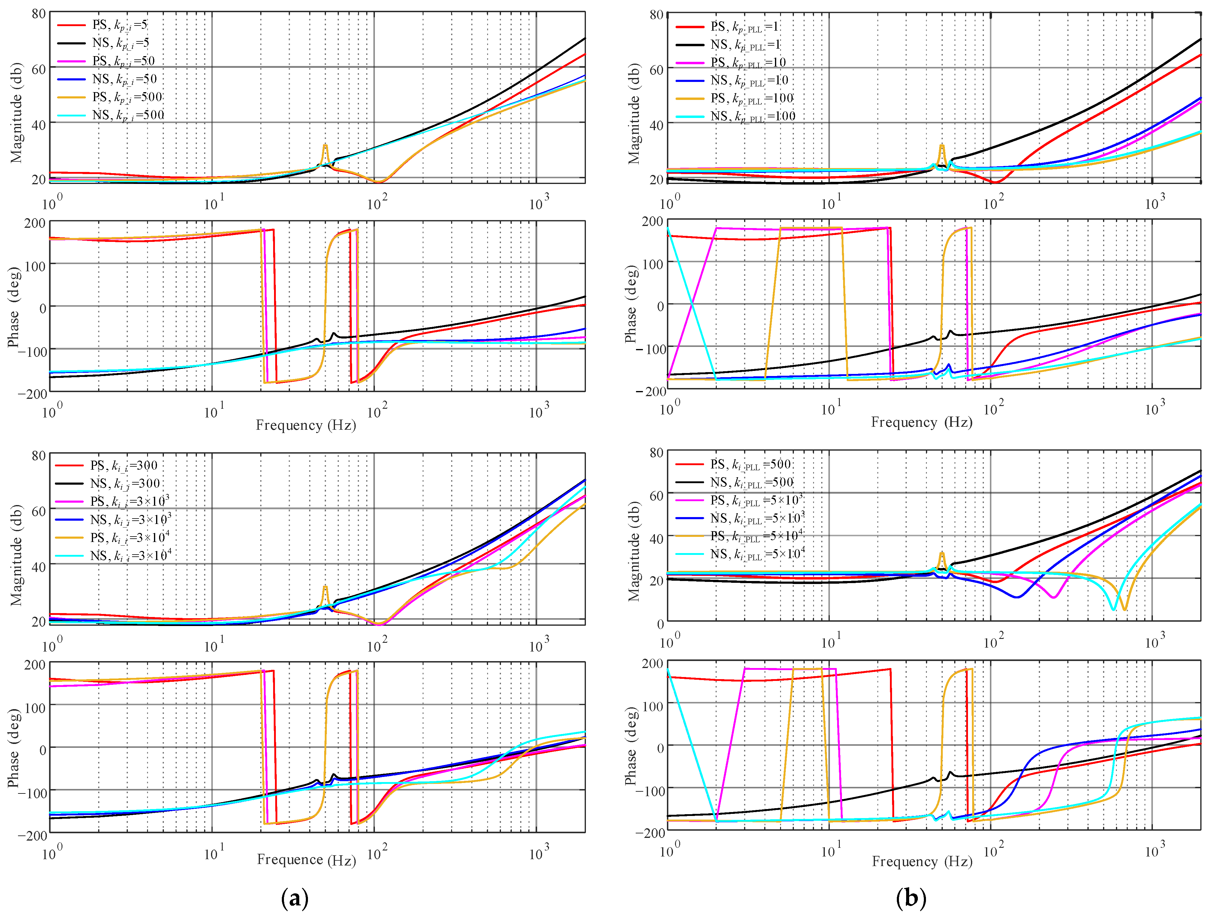
By modifying the proportional and integral coefficients of the phase current control while keeping the other control parameters constant, based on the system parameters presented in
Table 2, the impedance frequency characteristics of the MMC are depicted in
Figure 10a.
As the proportional coefficient of the phase current control increases, the impedance magnitude of the converter in the mid- to high-frequency range decreases, and the phase lag surpasses −90°. The MMC exhibits a capacitive impedance with a small negative resistance, leading to a potential interaction with the inductive impedance of the AC system and the possibility of resonance instability. With an increase in the integral coefficient, the impedance of the converter in the high-frequency range changes from capacitive to inductive, leading to improved damping characteristics and phase margin of the system. The impact of the phase current control parameters on the impedance characteristics of the MMC primarily occurs in the mid- to high-frequency range.
Modifying the proportional and integral coefficients of the PLL, while keeping the other control parameters constant, results in the impedance characteristics of MMC depicted in
Figure 10b. With an increase in the proportional and integral coefficients, the impedance magnitude of the MMC decreases in the mid- to high-frequency range, and the frequency range of capacitive negative damping is extended. Specifically, the rise in the proportional coefficient leads to a decrease in the system’s phase margin, thereby raising the risk of resonance instability, particularly in scenarios with weak grid connections. In the case of increasing the integral coefficient, the impedance magnitude of MMC exhibits a downward resonance peak at high frequencies. Additionally, the impedance phase above the resonance peak frequency changes from capacitive to inductive, resulting in an improvement in the system’s damping characteristic. The impedance magnitude of the MMC decreases significantly in the frequency range under the resonance peak frequency. This results in a reduction in the frequency at which it intersects with the impedance of the inductive AC grid, causing a downward shift in the resonance frequency due to the negative damping effect.
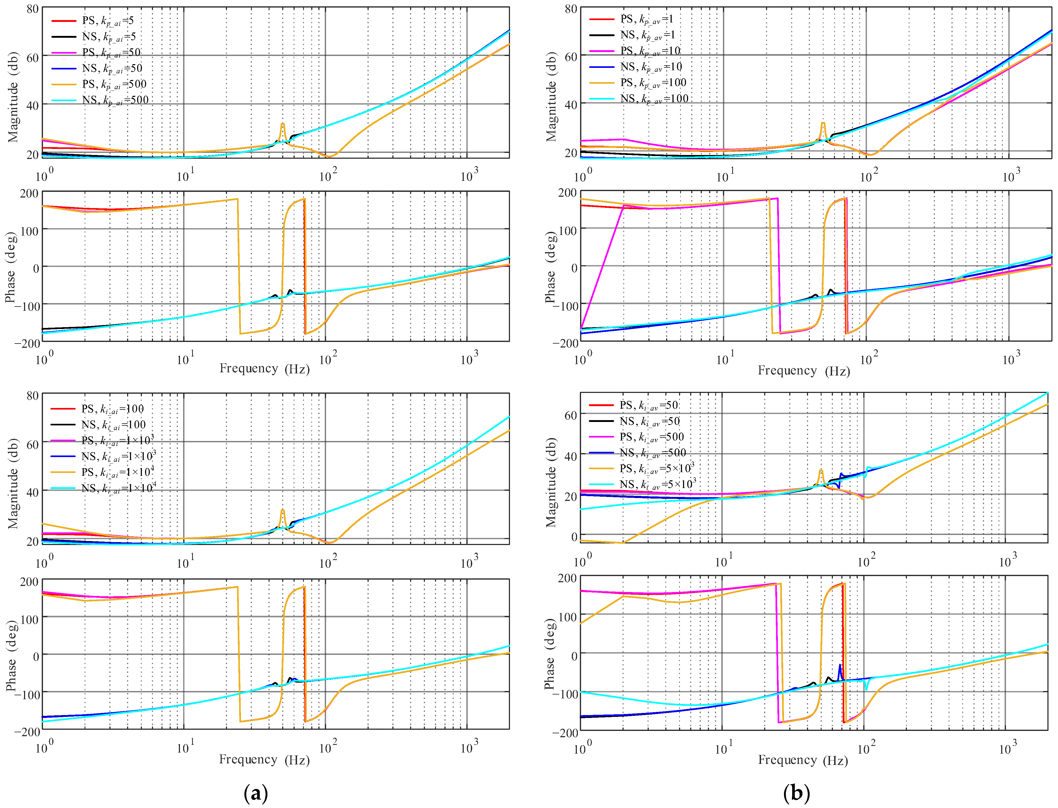
As shown in
Figure 11a,b, the proportional and integral coefficients of the power control are increased.
The increment of the kp_PQ causes the impedance magnitude of the MMC to improve over a wideband frequency range. At frequencies higher than 100 Hz, the positive- and negative-sequence impedance phases gradually shift towards capacitive and inductive, respectively. The distribution range of the negative damping characteristics of the positive-sequence impedance of MMC is expanded, and the possibility of resonance occurring through its interaction with the grid impedance is increased.
The main effect of the ki_PQ is to increase the impedance magnitude of the positive-sequence converter below 300 Hz, with minimal influence on the high-frequency impedance magnitude of the MMC. There is a delayed phase transition in the positive-sequence impedance of the MMC from 70 Hz to 110 Hz, while simultaneously expanding the distribution range of capacitive negative damping in 100~600 Hz. As the integral coefficient increases, it induces resonance instability at the intersection point of the impedance magnitudes between the MMC and power grid, which were previously capable of maintaining stable operation. The present research indicates that power control has a significant impact on low-frequency impedance characteristics. Nevertheless, when investigating high-frequency resonance problems, it is crucial to recognize that ignoring control parameters of the power control can introduce errors in stability analysis.
The influence of the CCSC parameters on the impedance frequency characteristics of the MMC is shown in
Figure 11b. However, the proportional coefficient generates resonant peaks of negative-sequence impedance close to the fundamental frequency, thereby introducing a risk of negative damping resonance in the system. The influence of the integral coefficient in CCSC on the impedance can be ignored.
As shown in
Figure 12a,b, the circulating current inner loop control parameters of the capacitor voltage averaging control have minimal impact on the impedance characteristics of the MMC. In
Figure 12b, as the integral coefficient of the submodule average capacitor voltage outer loop increases, there is a significant reduction in the impedance magnitude of the MMC within the frequency range of 0 to 10 Hz.
5. Analysis of High-Frequency Resonance of Grid-Connected MMC
The analysis results from
Section 4.3 indicate that the MMC impedance is significantly influenced by the PLL, phase current control with voltage feedforward, and power control in high-frequency range. Inadequate design of control parameters can lead to the undesired negative damping effect in the converter impedance. In this section, we begin by presenting the stability criteria and proceed to analyze the high-frequency resonance phenomenon in the MMC grid-connected system, considering both AC grid strength and control parameter perspectives. With the specific control parameters, we can identify the threshold of AC grid strength at which high-frequency resonance is avoided. Under the premise of a weak grid, a detailed examination is presented to compare the frequency characteristics of diverse control parameter settings by employing both detailed wideband impedance and conventional impedance models. Furthermore, the study investigates the effects of voltage feedforward and submodule capacitor voltage control on the results of the stability analysis of the interconnected system.
5.1. Stability Criterion
The frequency-domain impedance model of the MMC proposed in this paper captures the equivalent characteristic of the converter’s AC-side port. In
Figure 13, the impedance-based analysis method divides the interconnected system into two main components: power electronic devices and the AC grid. When transferring power between the converter and the AC grid, MMC can be approximated as a parallel connection of a current source and the impedance of the converter. To maintain steady AC voltage at the point of common coupling (PCC), the AC grid is equivalent to the series connection of a voltage source and the internal impedance. The interconnected system can be simplified and represented by the equivalent circuit depicted in
Figure 13.
Where
Ic(
s) is defined as the equivalent output current of the MMC under constant power control, and
Zeq(
s) corresponds to the sequence impedance of the MMC established in this paper.
Zg(
s) denotes the equivalent impedance of the AC system, considering factors such as the converter transformer, transmission lines, and grid strength.
Vg(
s) signifies the equivalent ideal voltage source of the AC grid.
Ig(
s) denotes the current at PCC which can be represented in the frequency domain as follows:
The stability of the current source Ic(s) is determined by the control performance of the converter. When the MMC operates stably under an ideal AC voltage source, Ic(s) remains stable. If the AC grid voltage Vg(s) remains constant and Zeq(s) is nonzero, Vg(s)/Zeq(s) is capable of maintaining stability. Thus, the overall stability of the interconnected system can be realized. To simplify the analysis, it is commonly assumed that the MMC can maintain stable operation when connected to an ideal grid, while the equivalent voltage source of the AC system remains constant. Consequently, 1/[1 + Zg(s)/Zeq(s)] determines the overall stability of the interconnected system.
Considering the second term on the right side of Equation (38), it can be interpreted as a negative feedback system with an open-loop transfer function of Zg(s)/Zeq(s), and the stability of the system is maintained when it satisfies the Nyquist stability criterion. Based on the Nyquist stability criterion, it is observed that when the MMC integrated into AC grids of varying strengths, there is an intersection between the impedance magnitude of Zeq(s) and Zg(s). At the frequency corresponding to a phase difference of 180°, the value of 1 + Zg(s)/Zeq(s) equals zero, leading to resonance instability in the system. From the perspective of impedance characteristics, due to the rapid internal control functions, the converter is represented as a capacitive reactance with negative resistance at the resonant frequency, and when interacting with the equivalent impedance of the AC system, an equivalent circuit is formed to generate system resonance.
5.2. Impact of Different Power Grid Strength
As more power electronic devices are connected to the grid, their capacity becomes a larger proportion of the grid. The risk of resonance when MMC is connected to a weak power grid also increases. Considering MMC connected to different grid strengths, the Nyquist criterion is utilized to identify the minimum grid strength where resonance instability occurs. This section investigates the influence of this limit on the resonance characteristics in grid-connected MMC.
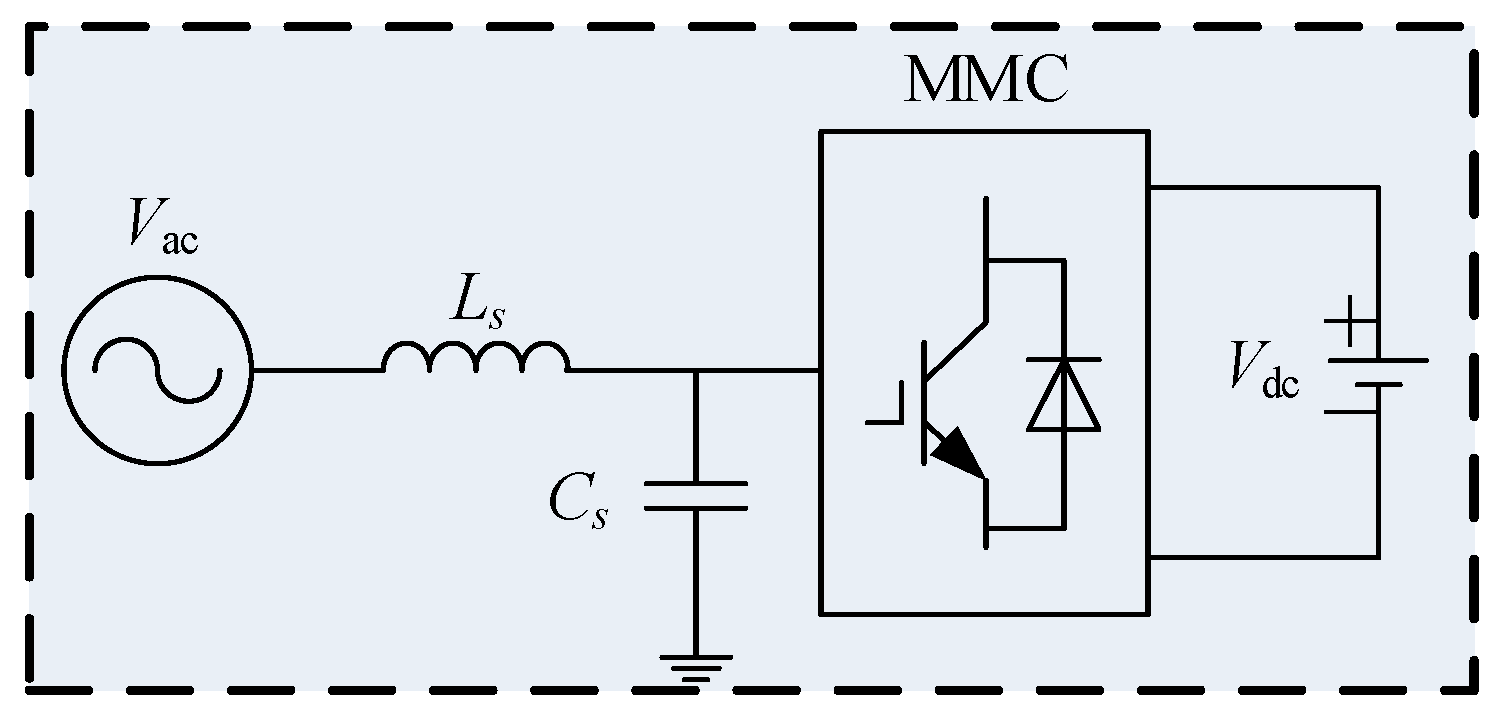
The utilization of MMC grid-connected systems is widespread in scenarios where distributed generation and emerging DC load access to AC grids. The converter is linked to the AC grid through devices like transmission lines and transformers. The typical circuit structure is illustrated in
Figure 14.
The equivalent resistance of the AC grid is neglected, and the capacitor coupling to the ground of the transmission line is added. The equivalent parallel capacitance at the AC terminal of the converter is set to 40 μF [
17], while the transformer and ideal voltage source impedances are combined and approximated as a series inductance. The grid impedance
Zg(
s) is formed by the parallel connection of the capacitance and inductance at PCC. Taking the impedance characteristics of the MMC shown in
Figure 10b as an example, with a proportional coefficient
kp_PLL set to 10, all other circuit and control parameters remain unchanged as listed in
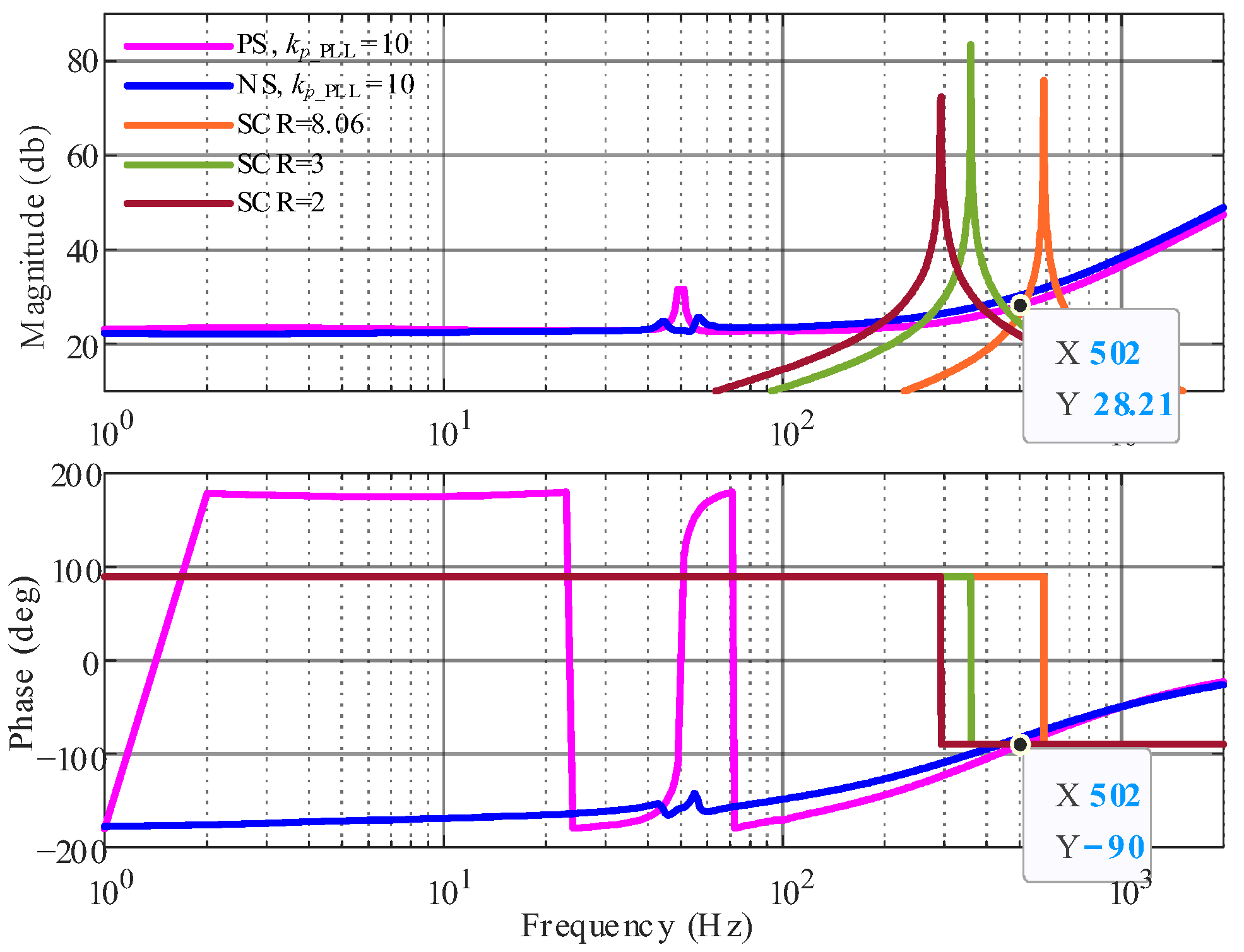
Table 2. When the frequency is 502 Hz, the phase of the positive-sequence impedance of the converter is −90° (capacitive), and the magnitude is 28.21 dB. If the magnitude of the impedance
Zg(
s) of the AC system is the same (
Ls = 1.9 mH) and the phase is 90° (inductive), the
Zg(
s)/
Zeq(
s) is −1, and the system is resonant instability. The grid strength is represented by the short-circuit capacity ratio (SCR), considering that the rated capacity of the MMC is 30 kVA as shown in
Table 2,
Ls = 1.9 mH corresponds to SCR = 8.06. Frequencies higher than 502 Hz result in an increasing phase of the MMC impedance, the phase margin meets the requirement of stable operation of the system.
As the grid strength increases, the resonant frequency of the equivalent impedance
Zg(
s) shifts towards higher frequencies. When SCR > 8.06, at the frequency corresponding to the intersection of the converter and grid impedance magnitudes, the phase difference is less than 180°. Under the control parameters shown in
Figure 10b, the critical grid strength limit for avoiding resonance instability is SCR = 8.06. There is a risk of resonance instability in the system when the grid strength is lower than this threshold. Furthermore, when the weak grid is set to SCR = 2 and 3, the AC system demonstrates an equivalent series inductance of 5.11 mH and 7.66 mH, respectively. The frequency characteristics of the system impedance for these three grid strengths in
Table 3 and converter impedance are illustrated in
Figure 15.
With the continuous reduction of power grid strength, the magnitude intersection point of Zg(s) and Zeq(s) shifts to low frequency, and the phase difference between them is greater than 180°. Therefore, the resonant frequency of the interconnected system decreases. The practical topology and operation of the power system are highly complex, resulting in the presence of multiple magnitude resonance peaks and phase discontinuities in Zg(s) over a wide frequency range. Then, it interacts with the wideband impedance characteristics caused by the internal control of MMC, leading to more complicate resonance problems.
5.3. High-Frequency Resonance of MMC Connected to the Weak Power Grid
The negative damping effect on the impedance characteristics of the MMC is caused by the inappropriate design of control parameters. In a typical MMC system connected to a weak power grid, if the equivalent impedance of the AC grid and the converter do not satisfy the stability criterion, the system will experience resonance instability caused by the negative damping effect. To analyze the resonance instability, a real-time digital simulation model of MMC connecting to the weak grid (SCR = 3) was built in OP5600 and the equivalent circuit structure is shown in
Figure 14. The control parameters of different control loops were modified in the simulation process, taking the proportional coefficient of PLL as a specific example.
Figure 16 presents the waveforms of the current response between the MMC and the grid for two cases:
kp_PLL = 1 and
kp_PLL = 10.
From the perspective of impedance characteristics, the necessity of wideband impedance modeling for system resonance analysis is verified in this section.
Figure 17 presents the impedance response of
Zg(
s); the positive- and negative-sequence impedances of the MMC,
Zp1(
s),
Zn1(
s),
Zp2(
s), and
Zn1(
s), considering voltage feedforward and capacitor voltage control, with
kp_PLL set to 1 and 10;
Zp0(
s) and
Zn0(
s) without the aforementioned control functions and
kp_PLL = 10.
Zg(
s) exhibits parallel resonance at 359 Hz, with inductive and capacitive characteristics on either side of the resonance frequency. At a frequency of 216 Hz, the inductive impedance
Zg(
s) is equal in magnitude to the capacitive
Zp2(
s). The phase angle of
Zp2(
s) is −131.6°, and the phase difference between
Zg(
s) and
Zp2(
s) exceeds 180°, resulting in high-frequency resonance in the interconnected system caused by the negative damping characteristics of the MMC.
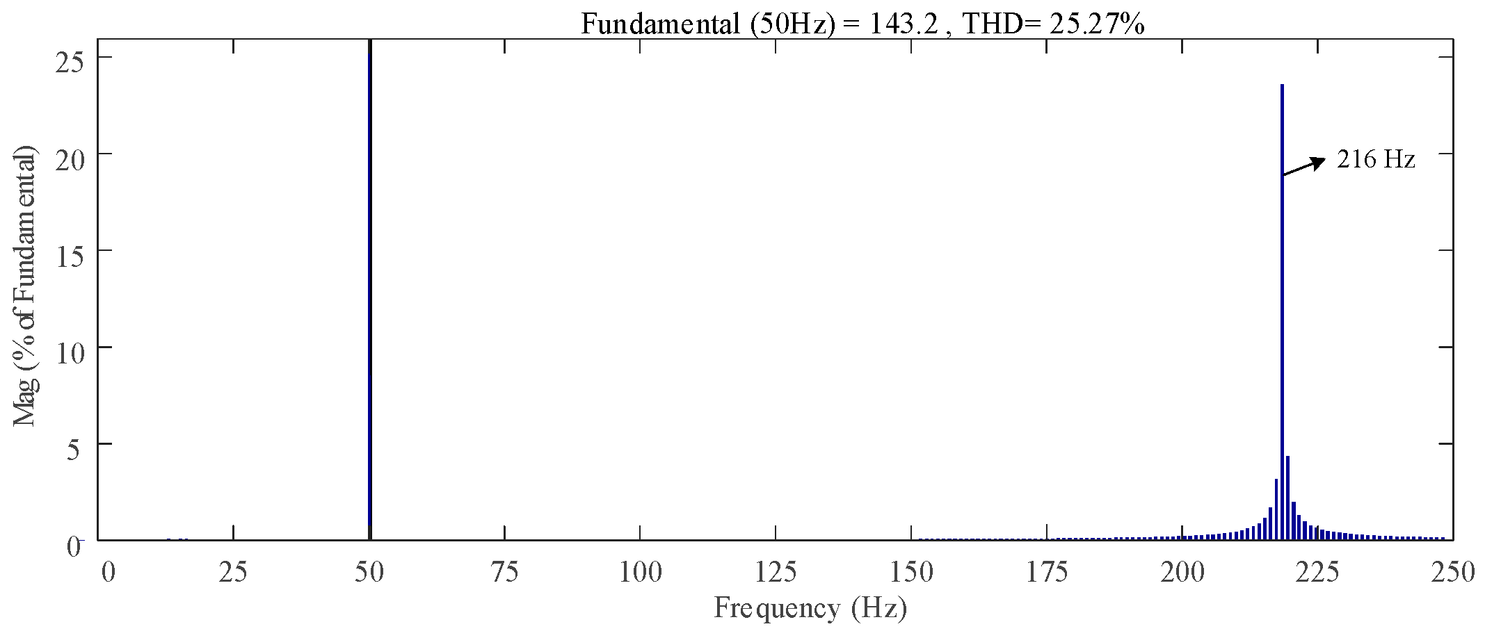
Figure 18 depicts the frequency distribution of the current response after Fourier decomposition. The corresponding frequency of the resonant component is consistent with the frequency of the intersection of
Zp2(
s) and
Zg(
s) magnitudes, providing evidence for the accuracy of the proposed wideband impedance modeling method. The phase difference corresponding to the magnitude intersection frequency of
Zp1(
s),
Zn1(
s), and
Zg(
s) is less than 180°, which satisfies the stability criterion of the system. Except for the fundamental and resonance frequency, the magnitude of the grid-connected current is close to zero in the remaining interval of tested frequencies. Reasonable design of control parameters can eliminate the risk of resonance instability. According to the phase difference at the magnitude intersection frequency of
Zp0(
s),
Zn0(
s), and
Zg(
s), the analysis results show that the system can maintain stable operation. The existing impedance modeling without considering voltage feedforward and capacitor voltage control will introduce errors in stability analysis.
