Article

Modelling and Analysis of Inter-Turn Short-Circuit Faults for Large-Power SPM Wind Generators

1
Electrical Machines & Drives Group, Department of Electronic and Electrical Engineering, University of Sheffield, Sheffield S10 2TN, UK
2
Siemens Gamesa Renewable Energy Limited, North Campus, Broad Lane, Sheffield S3 7HQ, UK
*
Author to whom correspondence should be addressed.
Energies 2023, 16(12), 4723; https://doi.org/10.3390/en16124723
Submission received: 27 April 2023 / Revised: 26 May 2023 / Accepted: 13 June 2023 / Published: 15 June 2023

Abstract

:
This paper proposes a general analytical model for large-power surface-mounted permanent magnet (SPM) wind generators under inter-turn short-circuit (ITSC) faults. In the model, branch currents rather than phase currents are used as state variables to describe the electromagnetic behavior of the faulty machine. In addition, it is found that the multiphase Clarke transformation can be used to simplify the proposed fault model with the inductances calculated analytically or numerically using finite element analysis. With the latter, both linear and nonlinear inductances can be obtained, and the non-linear inductances are used for the fault modelling of large power rating machines due to larger electrical loading and heavier magnetic saturation. With the developed fault model, studies of scaling effects (different power ratings such as 3 kW, 500 kW and 3 MW) and the influence of fault location on the electromagnetic performance of SPM generators with series-parallel coil connections have been carried out. The simulation results show that large-power SPM wind generators are vulnerable to ITSC faults when a relatively small number of turns are short-circuited and a single-turn short-circuit fault at the top of the slot is found to be the worst case.

1. Introduction

Due to the concerns about the depletion of non-renewable resources and significant global climate change, many countries are now resorting to renewable energy [1]. Wind energy, as one of the most promising renewable energy sources, has been well developed in the past 30 years. However, improving the reliability of wind turbine systems is still an important topic to both academia and industry [2,3]. As the size of wind turbines becomes larger, the loss of a single wind turbine unit leads to significant loss in the generated revenue. For this reason, some investigations have been conducted by major wind turbine manufacturers to obtain statistical data on the annual failure rate and downtime of major components of wind turbines, as reported in [4]. It was found that the wind generator and gearbox, as two of the key components of the powertrain, have the longest downtime, although they are less prone to failure than the power converters and their associated control units. Therefore, it is necessary to study the faults of wind generators and try to reduce their downtime by detecting their faults at an early stage and then optimizing the maintenance schedules.
With regard to wind generators, there are many different types, including permanent magnet synchronous generator (PMSG), squirrel cage induction generator (SCIG), wound rotor induction generator (WRIG), doubly fed induction generator (DFIG) and wound rotor synchronous generator (WRSG) [5]. In addition, line-start permanent magnet synchronous machines are also widely used in relatively constant speed applications, such as pumps and fans [6,7]. However, they all have similar fault types and distribution [8]. Amongst all the faults of these wind generators, the winding fault, as the second most frequent fault, has attracted significant interest in the past 30 years [8,9,10,11,12,13,14,15]. It has been reported by the authors in [8] and the Electrical Apparatus Service Association (EASA) that there are five major winding faults: (1) inter-turn (turn-to-turn) short circuit (ITSC), (2) coil-to-coil short circuit, (3) open circuit of one phase, (4) phase-to-phase short circuit, and (5) coil-to-ground short circuit. Amongst all the faults, the inter-turn short-circuit (ITSC) fault, often regarded as one of the root causes of other winding faults, has attracted increasing attention from researchers over the last few decades [12,14,16,17].
From the fault detection and protection perspective, it would be much better if the changes in machine currents and voltages under ITSC faults could be predicted and understood. This would help to develop a model-based fault detection method or increase the sensitivity and accuracy of the available techniques before doing any test [18]. A cost-effective fault model is especially useful for large-power electrical machines because performing fault tests on them is costly, difficult and often destructive. For these reasons, some prior work on ITSC fault modelling of different electrical machines has been carried out by researchers [10,11,12,19,20,21,22,23,24,25]. In the literature, there are three well-established methods to model ITSC faults, i.e., the analytical approach, magnetic equivalent circuit, and finite element method (FEM).
The advantage of the analytical approach is that it is generic and is applicable to machines with any power rating, although it can be less accurate, and the analytical calculation of inductances used in the fault model can sometimes be very complex. As for the magnetic equivalent circuit and FEM, although they have better accuracy, they are often much more time consuming, particularly for large-power electrical machines under ITSC faults. This is mainly because the full models required for large-power electrical machines with ITSC faults lead to many more mesh elements in the FE models or flux tubes in the magnetic equivalent circuit models; hence, they require much more time to solve at each step to maintain appropriate accuracy. If the full models of large-power electrical machines with a large number of slots and poles are interfaced with PWM converters (co-simulation) to simulate faulty machine behavior under real operating conditions, the long simulation time (which could be many days or even months) using common office computers would not be acceptable at the machine design stage.
Therefore, it is desirable to develop a relatively simple general analytical fault model that can use either analytical or FE inductance parameters. However, it has been reported in [10,19,20] that a system with a large number of first-order differential equations is required to characterize the fault model when loop or branch currents are used as state variables, which makes the ITSC fault modelling of large-power electrical machines very challenging. Therefore, it would be very useful if the fault model could be simplified.
In [21,22], the authors proposed a simplified fault model for fractional-slot SPM machines with series-parallel coil connections by assuming that all branch currents in the remaining healthy phases were equal when the ITSC fault occurred in one branch of the faulty phase. However, this assumption might not be applicable to large-power integer-slot SPM wind generators. On the other hand, the authors in [26,27] try to simplify the fault model by assuming that most of the mutual inductances are zeros. However, the validity of this assumption is also questionable for large-power SPM wind generators. Overall, no relatively simple and general analytical fault model has been proposed.
To fill this research gap, this paper proposes a simple general analytical fault model in a concise block matrix form for large-power SPM wind generators, in which the branch currents are used as state variables. In addition, the multiphase Clarke transformation is proposed to simplify the fault model. As one of the most important parameters in the fault model, the inductances can be calculated using both the analytical approach and FEM. The analytical approach is used to calculate the inductances of single-layer and distributed overlapping windings (slot/pole/phase (SPP) is equal to 1), which are often adopted by large-power SPM wind generators. As for the inductance calculation using FEM, both linear and nonlinear inductances have been calculated. With the developed fault model, studies of scaling effects such as power ratings (3 kW, 500 kW, 3 MW) and the influence of the fault location considering the series-parallel coil connections have also been carried out. It should be mentioned that although the scaling effect study was investigated in [28], the large-power SPM machines were assumed to have series-connected coils, which is often not the case in practice.

2. Analytical Modelling of ITSC Faults of SPM Wind Generators

Figure 1 shows the circuit schematic of the studied SPM wind generators. The circuit schematic in Figure 1 is also used in the FE model for inductance calculation in Section 3.2, where the meanings of A1_hc, A11_ht, A11_hb, and A11_fm are explained in more detail. It is worth noting that in the FE models of the SPM wind generators, one FEM coil represents one parallel branch that contains r coils in series, and each phase has n parallel branches.
In addition, the ITSC fault is assumed to occur in A11_fm turns of a certain coil in the first branch (A1 branch) of phase A. If the switch in Figure 1 is closed, i.e., a short circuit occurs, a large current will circulate in the short-circuited path marked in red, which causes the branch currents in each phase to become unbalanced, i.e., the branch currents in each phase are not equal anymore. To consider this situation, the branch currents are used as state variables to describe the machine behavior under an ITSC fault. Therefore, the voltage equations for every circuit branch and the short-circuited path can be expressed in a concise block matrix form as (1):
v A v B v C 0 = L A A M A B M A C M A f M B A L B B M B C M B f M C A M C B L C C M C f M A f T M B f T M C f T L A 1 f , A 1 f d d t i A i B i C i f + R c b i A i B i C 0 + e A e B e C e A 1 f + i f 0 0 0 i A 1 f R A 1 f 0 0 0 0 R f i f
where v , i , and e are column vectors that represent branch-to-neutral voltages ( v ), branch back-EMFs ( e ) or branch currents ( i ) for the phase windings A, B and C. For example, e A = e A 1 e A 2 e A n T represents the back-EMFs in every branch of phase A. This column vector has n entries, where n is the number of parallel branches described earlier. In terms of L x x and M x y (“ y ” denotes another phase winding different from x ). In this paper, they are referred to as branch inductance matrices. The entry L x x i , j of L x x represents the inductive coupling between the ith and jth branches of the same phase x . Similarly, the entry M x y i , j of M x y describes the inductive coupling between the ith branch of phase x and the jth branch of phase y . These definitions can be written concisely as L x x i , j = M x i x j and M x y i , j = M x i y j .
Additionally, R c b in (1) is the branch resistance. As for R A 1 f , L A 1 f , A 1 f , e A 1 f , they are the resistance, self-inductance, and induced back-EMF of the short-circuited turns, respectively. It can be easily seen that e A 1 f = μ 1 / r e A , where the coil faulty turn ratio μ 1 is defined as μ 1 = n f / n c , r is the number of coils connected in series in every parallel branch, and e A is the branch back-EMF of phase A. With regard to n f and n c , they are the number of short-circuited turns A11_fm and the number of turns per coil, respectively. Furthermore, i f and i A 1 f ( = i A 1 i f ) are the currents in the external short-circuited path and short-circuited turns, as shown in Figure 1. Meanwhile, R f in (1) is the contact or insulation resistance between two short-circuited points. It is worth noting that, in practice, R f would change according to the degree of insulation degradation. However, for simplicity, in this paper, unless specifically highlighted, R f has been assumed to be zero, meaning that the worst case of ITSC fault has been considered.
The last remaining terms to be explained are the three faulty inductance vectors M A f , M B f , and M C f . They represent the inductive couplings between the short-circuited turns and the branches in all three phases, which can be expressed as
M A f = M A 1 , A 1 f M A 2 , A 1 f M A n , A 1 f T M B f = M B 1 , A 1 f M B 2 , A 1 f M B n , A 1 f T M C f = M C 1 , A 1 f M C 2 , A 1 f M C n , A 1 f T
where M A 1 , A 1 f = L A 1 f , A 1 f + M A 1 h , A 1 f . M A 1 h , A 1 f represents the mutual inductance between the remaining healthy turns and the short-circuited turns in the branch A1.
Once all the branch currents in the three-phase windings and the current in the short-circuited turns are known, the electromagnetic torque (Nm) under an ITSC fault can be determined and expressed as
T e = e A T i A + e B T i B + e C T i C e A 1 f i f ω r m + T c o g
where ω r m is the rotor mechanical speed (rad/s), and T c o g is the cogging torque (Nm), which can be easily calculated using FE models.
Although the fault model is now complete, if the three-phase windings are Y-connected and the neutral point is not accessible, then the branch-to-neutral (or phase) voltages v A , v B , and v C cannot be determined directly. This problem can be solved if the following three conditions are satisfied:
(1)
All branch-to-neutral voltages such as v A 1 to v A n of the same phase are equal and the branch back-EMFs of the same phase such as e A 1 to e A n are equal.
(2)
All branch inductance matrices are circulant matrices (see Appendix A).
(3)
The sum of three phase currents is zero.
Adding all the circuit branch voltage equations together will yield
v A + v B + v C = e A + e B + e C 1 n R A 1 f i f + k = 1 n M A f ( k ) + M B f ( k ) + M C f ( k ) d i f d t
where e A , e B and e C are branch back-EMFs of phases A, B and C. M A f ( k ) , M B f ( k ) , and M C f ( k ) represent the kth elements of M A f , M B f , and M C f , respectively.
Now the sum of the three branch-to-neutral voltages v A , v B , and v C is known. Using (4), the three branch-to-neutral voltages can be easily determined separately from the two line voltages v A B and v B C using the following equation:
v A B = v A v B v B C = v B v C = v A + 2 v B ( v A + v B + v C )
Equations (1)–(3) clearly show that the number of first-order differential equations to characterize the fault model using branch currents as state variables is determined by the number of parallel branches. This means that a total of 3 n + 2 first-order differential equations (2 mechanical equations have been included although they are not shown) must be used to predict the machine behavior under an ITSC fault for the studied SPM wind generators with n parallel branches in every phase. If the number of differential equations for the fault model is large, it is very difficult to build and solve such a model in MATLAB/Simulink R2018a or other similar software. To overcome this difficulty, the multiphase Clarke transformation is proposed in Section 4 to simplify the fault model.

3. Inductance Calculation

It can be seen from Section 2 that if the number of parallel branches is large, many inductance elements in the branch inductance matrices and in the three faulty inductance vectors have to be determined when building the fault models using simulation software such as MATLAB/Simulink. This is especially the case for large-power low voltage SPM wind generators with many parallel branches in each phase to reduce the voltage stresses of their interfaced converters. Therefore, this section will focus on the theoretical calculation of inductances using both an analytical approach and FEM.

3.1. Analytical Approach

It is often convenient to use an analytical approach to calculate inductances at an initial design stage when the winding configuration of the studied machine is not complex. Unlike the large-power synchronous machines in [20], large-power SPM wind generators often have a simple winding configuration. In this paper, the distributed single-layer winding with a slot/pole/phase (SPP) equal to 1 has been used for the fault modelling, as shown in Figure 2.
For the phase self- and mutual-inductances, there are three components, i.e., air-gap, slot-leakage and end-turn leakage components, that often need to be calculated (or estimated according to their proportions) for accurate fault modelling [28,29]. However, for the investigated large-power SPM wind generators, the end-windings are often much shorter than the active windings in the slots. Therefore, the end-turn leakage components have been neglected for inductance calculation, and this neglect has been found to have little influence on the model accuracy. In addition, to simplify the analytical calculation of the inductances, it is assumed that the conductors completely fill the rectangular slot, and the shapes and the locations of the conductors are not considered. Otherwise, the inductance calculation using an analytical approach would be very complex. However, both the shapes and locations of the conductors can be relatively easily considered in the direct FE simulations if more accurate predictions are required.
Using the analytical approach (winding function approach + slot permeance method) in [28,29], all the elements of the branch inductance matrices of the studied SPM wind generators can be obtained. It is worth mentioning that due to the spatial distribution of the three-phase symmetrical windings, all the branch inductance matrices are circulant ones (see Appendix A). From Appendix A, it can be easily seen that if the elements in the first row of a circulant matrix are known, all the elements of the circulant matrix can be determined accordingly. Based on this characteristic, all the elements in the branch inductance matrices required for the fault model can be defined and calculated as
L A 1 A 1 = L B 1 B 1 = L C 1 C 1 = L 1 M A 1 A j = M B 1 B j = M C 1 C j = M 1 ( j = 2 , 3 , , n ) M A 1 B 1 = M B 1 C 1 = M 2 M A 1 B j = M B 1 C j = M 1 ( j = 2 , 3 , , n ) M A 1 C j = M 1 ( j = 2 , 3 , , n 1 ) M A 1 C 1 = M 1 + M α M A 1 C n = M 1 + M β
with
L 1 = μ 0 r e l e g e r ( 2 p r ) 2 p 2 π n c 2 + 2 r n c 2 μ 0 l e h s 3 S ω M 1 = μ 0 r e l e g e r 2 2 p 2 π n c 2   a n d   M 2 = 2 p 3 r 3 r M 1 M β = μ 0 r e l e g e 1 3 p π n c 2   a n d   M α = r 1 M β
where the meanings of μ 0 , r e , l e , g e , h s , S ω and p are the same as those in [28,29].
The remaining inductances to be calculated are the elements of the three faulty inductance vectors, and they are expressed as
M A 1 , A 1 f = L 11   a n d   M B 1 , A 1 f = M C n , A 1 f = M 22 M A j , A 1 f = M B j , A 1 f = M 11 ( j = 2 , 3 , , n ) M C j , A 1 f = M 11 ( j = 1 , 2 , , n 1 )
with
L 11 = L A 1 f , A 1 f + M A 1 h , A 1 f = L A 1 f , A 1 f g + L A 1 f , A 1 f s l o t + M A 1 h , A 1 f g + M A 1 h , A 1 f s l o t
where the air-gap and slot-leakage inductance components of L A 1 f , A 1 f and M A 1 h , A 1 f (indicated by subscripts “g” and “slot”) are the same as those shown in [29] and have to be calculated separately as follows:
L A 1 f , A 1 f g + M A 1 h , A 1 f g = μ 0 r e l e g e 2 p r 2 p 2 μ 1 π n c 2
L A 1 f , A 1 f s l o t = 2 μ 0 l e n c h s 2 h b h a 2 S ω h s 1 3 h a 2 3 h b
M A 1 h , A 1 f s l o t = 2 μ 0 l e n c h s 2 h a h b h a 2 2 S ω + h b h a 2 S ω h s h b + h a 2 h a 2
where h a and h b represent the two fault locations along the slot, and n f = n c h b h a / h s represents the number of short-circuited turns associated with the fault locations. They are illustrated in Section 3.2. In addition, M 11 and M 22 in (8) are expressed as
M 11 = μ 0 r e l e g e r 2 p 2 μ 1 π n c 2   a n d   M 22 = 3 r 2 p 3 r M 11

3.2. FEM Modelling

Although a direct FE simulation of large-power SPM wind generators under an ITSC fault using voltage sources is quite time-consuming, inductance calculation using FEM can often obtain accurate results in a short time. For the studied 3 MW SPM wind generator, it only takes several seconds to obtain all the linear inductances, and several hours to obtain all the nonlinear inductances using the flux linkage subtraction method when the core saturation is not heavy. These FE inductances can then be used in the fault model to predict the performance of the machines under an ITSC fault. It is worth mentioning that under an ITSC fault, the currents in the machine windings become asymmetric, and therefore, a full FE model is necessary to calculate all the inductances required in the fault model.
In Figure 3, the fault locations h a and h b related to the number of short-circuited turns (marked in red) are highlighted. The coil with short-circuited turns shown in Figure 1 is divided into three FEM coils with different numbers of turns. The A1_hc FEM coil represents the remaining r 1 healthy coils of the A1 branch. With regard to A11_hb and A11_ht FEM coils, they are the remaining healthy turns at the bottom and top of the two affected slots with short-circuited turns. The last FEM coil A11_fm in A1 branch represents the short-circuited turns in the middle of the two affected slots. In addition, one FEM coil in every other healthy branch of the three-phase windings is used to indicate it has r healthy coils connected in series.

3.3. Some Results of Inductance Calculations

The main parameters of the studied SPM machines are shown in Table 1. Due to space limitations, only some analytical and direct FE inductance results of the 500 kW machine are shown in Figure 4a,b as examples. In Figure 4c, the relative error of the inductances is the difference between the 2D analytical and FE inductances divided by the corresponding 2D FE inductances.
It can be seen from Figure 4c that some relative errors of the elements in the branch inductance matrices for the 500 kW SPM machine are quite large. For example, there is about 500% relative error for M A 4 A 1 , M B 4 A 1 and M C 4 A 1 . However, these inductances are very small, and the large error does not affect the accuracy of the fault model to a great extent, as shown in Section 5. It is also worth noting that, although not shown, the inductances of the 3 MW SPM machine also have similar characteristics.

4. Model Simplification Using Multiphase Clarke Transformation

As mentioned previously, the proposed fault model using branch currents as state variables requires many first-order differential equations to simulate the faulty machine performance, especially for large-power low-voltage SPM machines. In addition, very few elements of the branch inductance matrices are zeros. These are the two main reasons why it is difficult to construct a fault model for large-power low-voltage SPM machines. However, as the branch inductance matrices are circulant ones, the fault model can be greatly simplified when the original branch currents, voltages and back-EMFs are transformed into new variables using the multiphase Clarke transformation matrix C as follows:
f A f B f C = C 0 0 0 C 0 0 0 C f A f B f C
where f A , f B and f C are the corresponding transformed branch current, voltage, and back-EMF vectors. In addition, C has the power invariant form, i.e., C 1 = C T . As a result, it is easily seen that
f A f B f C = C 1 0 0 0 C 1 0 0 0 C 1 f A f B f C = C T 0 0 0 C T 0 0 0 C T f A f B f C
The new voltage equations after using the multiphase Clarke transformation can be written as
v A v B v C 0 = L A A M A B M A C C M A f M B A L B B M B C C M B f M C A M C B L C C C M C f M A f T C T M B f T C T M C f T C T L A 1 f , A 1 f d d t i A i B i C i f + R c b i A i B i C 0 + e A e B e C e A 1 f + C 0 0 0 0 C 0 0 0 0 C 0 0 0 0 1 R A 1 f i f 0 0 0 R A 1 f i A 1 f R f i f
where L x x = C L x x C T , and M x y = C M x y C T . “ x ” and “ y ” represent two different phases amongst A, B, and C. It is worth noting that no matter what kind of inductances (FE linear or nonlinear) are used in the fault model, L x x will all have diagonal forms because they are circulant and symmetric, and M x y will all have block diagonal forms, the elements of which are shown in Appendix B. In other words, after the transformation, the fault model is greatly simplified because the number of the first-order derivatives of state variables in every transformed circuit branch voltage equation represented by a first-order differential equation is reduced from 3 n + 1 to 3 or 5. In addition, i A 1 f ( = i A 1 i f ) has to be represented by i A 1 f [ = C T i A 1 i f ], indicating that the transformed branch currents are used as new state variables.
The torque equation now can be expressed as
T e = e A i A + e B i B + e C i C e A 1 f i f ω r m + T c o g
where i A , i B and i C are the phase currents, which are n times the corresponding transformed branch currents i A 1 , i B 1 and i C 1 .
In addition, the relationship between the equivalent phase self- and mutual-inductances for the three-phase windings with series-parallel-connected coils (LSP and MSP) and those with series-connected coils (LS and MS) can be established as follows:
L x x S P = 1 n j = 1 n L x x 1 j = 1 n 2 L x x S M x y S P = 1 n j = 1 n M x y 1 j = 1 n 2 M x y S
From (18), it can be seen that the concept of equivalent phase self- and mutual-inductances for three-phase windings with series-parallel-connected coils becomes “concrete” because they are now related to the mutual inductances between two branches in the same phase.

5. Simulation Results

A series of Matlab/Simulink simulations using analytical, FE linear and nonlinear inductances has been carried out for the 3 kW, 500 kW, 3 MW SPM faulty machines with distributed overlapping winding configurations. As the main purpose of this paper is to validate the fault model and model simplification method, for simplicity, the rotor speeds are kept constant and balanced three-phase sinewave voltages are fed to the fault model to shorten the simulation time. The inter-turn short-circuit faults are introduced when the machines operate under the rated condition, i.e., rated speed and torque with id = 0 A control. It is also worth mentioning that a system of 23 first-order differential equations is required to simulate the 500 kW faulty machine, and for the 3 MW machine, a system of 62 first-order differential equations needs to be built. Such large-scale systems of first-order differential equations are very complex and much more computationally demanding than that for a healthy machine (only four to six first-order differential equations are required).

5.1. Fault Simulations with Linear Inductances

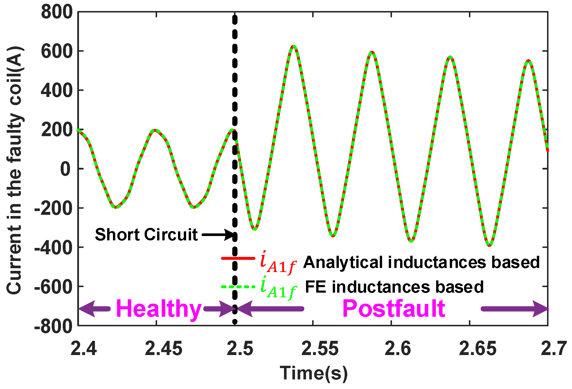
Due to limited space, only some typical results of the 3 MW SPM machine under the one-coil short-circuit fault are presented in this section. Compared with other fault scenarios, this fault case generally leads to the greatest imbalance in branch currents. In Figure 5, the currents of the faulty coil before and after the one-coil short-circuit fault are shown. A good match between the results from the two models using FE linear and analytical inductances can be observed. Although the results of other ITSC fault cases using analytical and FE linear inductances under different operating conditions are not shown here, they generally show good agreement. In addition, it can be observed that the fault current under a one-coil short-circuit fault increases significantly, about two to three times the current in the faulty coil before the fault.
Some steady-state branch currents in phases A and C before and after the one-coil short-circuit fault are illustrated in Figure 6. It is worth noting that the steady-state current waveforms before (2.4 to 2.5 s) and after the one-coil short-circuit fault (3.8 to 4 s) have been combined because the current transients last for quite a long time. By doing so, it is much easier to see the variation in currents before and after the short-circuit fault. In addition, since the results from the two models using analytical and FE linear inductances are very much similar, in Figure 6, only the results using the FE linear inductances are shown. It is also worth noting that the branch currents i A 3 to i A 20 are very much similar to i A 2 , and i C 3 to i C 19 are very much similar to i C 2 . Although not shown, the changes in the branch currents of phase B are negligible. These variations of branch currents before and after the short-circuit fault have also been observed in the 500 kW SPM machines. In addition, it is worth mentioning that the 3 kW SPM machine considered in this paper only has series-connected coils, and the results have already been shown in [28].
Unsurprisingly, as the 3 MW SPM machine has a large number of parallel branches and in each parallel branch, it has numerous series coils, the three-phase currents only change slightly before and after the one-coil short-circuit fault. However, lower order harmonics can still be observed in the d- and q-axis currents, as shown in Figure 7, and they can be used as a fault indicator for the fault detection purpose, as investigated in [31,32].

5.2. Fault Simulations with Nonlinear Inductances

In the previous section, FE linear inductances are used to validate the fault model using analytical inductances. However, in practice, the inductances are often nonlinear. This is particularly the case in the large wind power generators that often have large electrical loading and hence heavier magnetic saturation. As the impact of scaling (from 3 kW to 3 MW) will be investigated in this section, nonlinear inductances need to be used for more accurate modelling. As described earlier, the multiphase Clarke transformation developed in Section 4 can still be used to simplify the fault model with nonlinear inductances. Thus, some studies such as the scaling effect and fault location can be carried out in Matlab/Simulink in a more realistic way and without excessive increases in the modelling difficulty.

5.2.1. Scaling Effect

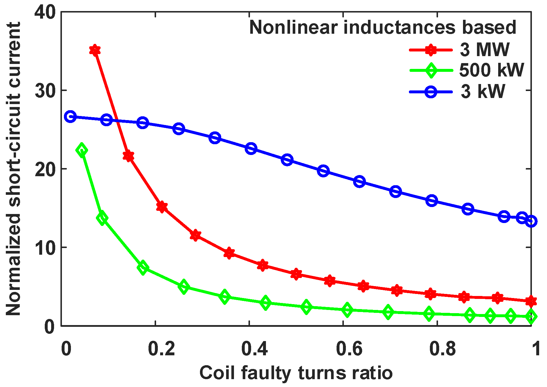
According to the previous analyses, the large-power SPM machines in this paper have series-parallel winding configurations, which are often used in offshore wind power generators. The normalized ITSC currents of PM machines with different power ratings (3 kW, 0.5 MW and 3 MW) versus coil faulty turns ratio are shown in Figure 8. The reference current values of these PM machines are their corresponding rated coil currents.

5.2.2. Influence of Fault Location

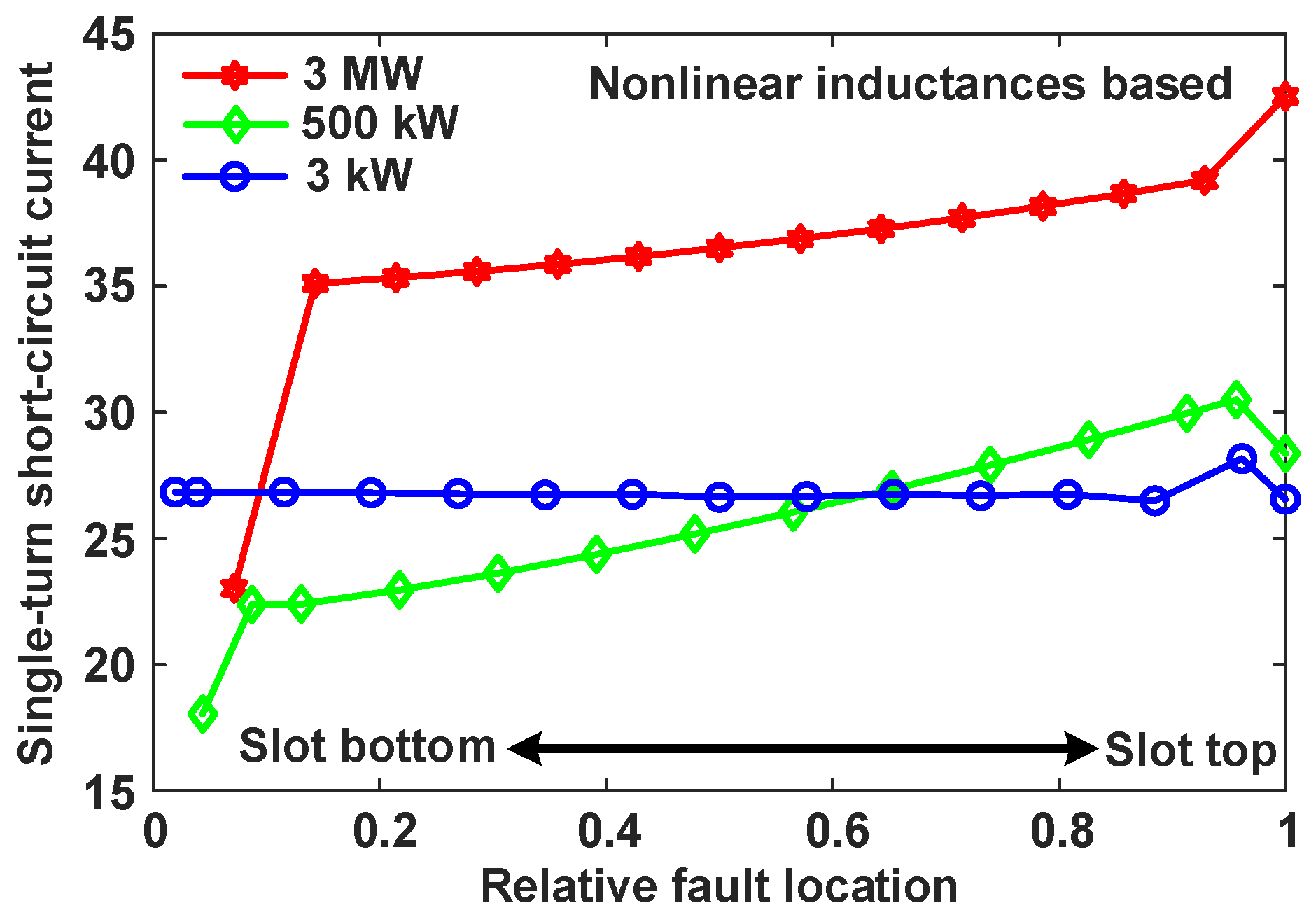
Although in the scaling effect study one of the fault locations was chosen to be at the bottom of the slot, i.e., h a = h s / n c , it is worth noting that the amplitude of the ITSC current actually depends on the two fault locations h a and h b . This is because all the elements of the three faulty inductance vectors M A f , M B f , and M C f are fault location dependent. It has been reported that the worst-case scenario for fractional-slot SPM machines under a single-turn short-circuit fault is a short circuit close to the slot opening [33,34,35]. However, to the best of our knowledge, there is no similar report on large-power SPM machines with series-parallel coil connections. Based on the proposed fault model and model simplification method, the influence of the fault location on the amplitude of the ITSC current under a single-turn short-circuit fault can be studied. The results are shown in Figure 9. For large-power SPM machines (500 kW and 3 MW), the worst-case scenario of the single-turn short-circuit fault is also a short circuit close to the slot opening. However, for low-power SPM machines (3 kW), the influence of fault location on the amplitude of the ITSC current is negligible. This is mainly because for the 3 kW machine, the amplitude of the ITSC current can be approximated to the ratio of the back EMF to the impedance of the short-circuited turn. Thus, the fault location has negligible influence on the amplitude of the ITSC current. However, for large-power machines such as the 500 kW and 3 MW machines, the amplitude of the ITSC current is affected by other inductances such as k = 1 n M A f ( k ) , k = 1 n M B f ( k ) , k = 1 n M C f ( k ) and L A 1 f , A 1 f . This conclusion is drawn by analysing the reduced-order fault model to approximately predict the amplitude of the ITSC current, which is based on the additional assumption that after the fault, all branch currents of the remaining healthy phases are equal.

6. Conclusions

This paper presents a general analytical model and model simplification method using multiphase Clarke transformation for large-power SPM wind generators under an inter-turn short-circuit (ITSC) fault. Calculation of inductances in the fault model using an analytical approach and FEM has been presented. It is found that the multiphase Clarke transformation can be used to simplify the fault model with FE linear and nonlinear inductances because all branch inductance matrices are circulant matrices. As a result, the simulations for large-power SPM wind generators under an ITSC fault can be carried out directly in an easier and more time-saving way while maintaining adequate accuracy using the simplified fault model with FE inductances. It is worth mentioning that the proposed fault model and model simplification method are generic and may be applied to other types of non-PM machines and also their multiphase counterparts with practical winding configurations. In addition, based on the simplified fault model, studies of scaling effects and the influence of fault location on the amplitude of ITSC current of PM machines with different power ratings (3 kW, 500 kW, 3 MW) have been carried out. The simulation results show that large-power SPM wind generators are vulnerable to ITSC faults when a relatively small number of turns are short-circuited, and the single-turn short-circuit fault at the slot top (close to slot opening) is the worst-case scenario.

Author Contributions

Writing—original draft, Z.M.; writing—review and editing, G.L. and Z.Z.; funding acquisition, R.C., A.T. and Z.A. All authors have read and agreed to the published version of the manuscript.

Funding

This work is supported by the UK Engineering and Physical Science Research Council (EPSRC) Partnership, a new partnership in Offshore Wind under Grant EP/R004900/1.

Data Availability Statement

Not applicable.

Conflicts of Interest

The authors declare no conflict of interest.

Appendix A

Regarding the circulant matrices, one important characteristic is that the elements of each row of a circulant matrix are identical to those of the previous row, but are moved one position to the right and wrapped around [36]. Its mathematical form can be expressed as follows:
c i r c L 0 , L 1 , , L n 1 = L 0 L 1 L 2 L n 1 L n 1 L 0 L 1 L n 2 L n 2 L n 1 L 0 L n 3 L 1 L 2 L 3 L 0
For simplicity, we define L c i r c = c i r c L 0 , L 1 , , L n 1 .

Appendix B

The multiphase Clarke transformation matrix is shown in (A2)
C = 2 n 1 2 1 2 1 2 1 2 1 2 1 c o s 2 π n c o s 2 × 2 π n c o s m × 2 π n c o s n 1 × 2 π n 0 s i n 2 π n s i n 2 × 2 π n s i n m × 2 π n s i n n 1 × 2 π n 1 c o s k × 2 π n c o s 2 × k × 2 π n c o s m × k × 2 π n c o s n 1 × k × 2 π n 0 s i n k × 2 π n s i n 2 × k × 2 π n s i n m × k × 2 π n s i n n 1 × k × 2 π n 1 c o s n 2 2 × 2 π n c o s 2 × n 2 2 × 2 π n c o s m × n 2 2 × 2 π n c o s n 1 × n 2 2 × 2 π n 0 s i n n 2 2 × 2 π n s i n 2 × n 2 2 × 2 π n s i n m × n 2 2 × 2 π n s i n n 1 × n 2 2 × 2 π n 1 2 1 2 1 2 1 m 1 2 1 2
In (A2), the assumption has been made that the number of parallel branches is an even integer. If the number of parallel branches is an odd integer, the last row in (A2) should be deleted and all ( n 2 ) / 2 terms appearing in the third- and second-to-last rows have to be replaced with ( n 1 ) / 2 .
The nonzero elements of the transformed branch inductance matrices are given as (A3).
C L c i r c C T i , j = C L c i r c C T 1 , 1 = h = 0 n 1 L h C L c i r c C T 2 k , 2 k = C L c i r c C T 2 k + 1 , 2 k + 1 = h = 0 n 1 L h c o s 2 π h n   k = 1 , 2 , , n 2 2 C L c i r c C T 2 k , 2 k + 1 = C L c i r c C T 2 k + 1 , 2 k = h = 0 n 1 L h s i n 2 π h n k = 1 , 2 , , n 2 2 C L c i r c C T n , n = 1 h h = 0 n 1 L h

References

  1. Yaramasu, V.; Wu, B.; Sen, P.C.; Kouro, S.; Narimani, M. High-power wind energy conversion systems: State-of-the-art and emerging technologies. Proc. IEEE 2015, 103, 740–788. [Google Scholar] [CrossRef]
  2. Freire, N.M.A.; Cardoso, A.J.M. Fault detection and condition monitoring of PMSGs in offshore wind turbines. Machines 2021, 9, 260. [Google Scholar] [CrossRef]
  3. Badihi, H.; Zhang, Y.; Jiang, B.; Pillay, P.; Rakheja, S. A comprehensive review on signal-based and model-based condition monitoring of wind turbines: Fault diagnosis and lifetime prognosis. Proc. IEEE 2022, 110, 754–806. [Google Scholar] [CrossRef]
  4. Blaabjerg, F.; Liserre, M.; Ma, K. Power electronics converters for wind turbine systems. IEEE Trans. Ind. Appl. 2012, 48, 708–719. [Google Scholar] [CrossRef] [Green Version]
  5. Yaramasu, V.; Wu, B. Model Predictive Control of Wind Energy Conversion Systems; IEEE Press Series on Power Engineering; Wiley: Hoboken, NJ, USA, 2017. [Google Scholar]
  6. Palangar, M.F.; Soong, W.L.; Bianchi, N.; Wang, R.-J. Design and optimization techniques in performance improvement of line-start permanent magnet synchronous motors: A review. IEEE Trans. Magn. 2021, 57, 900214. [Google Scholar] [CrossRef]
  7. Faramarzi Palangar, M.; Mahmoudi, A.; Kahourzade, S.; Soong, W.L. Simultaneous efficiency and starting torque optimization of a line-start permanent-magnet synchronous motor using two different optimization approaches. Arab. J. Sci. Eng. 2021, 46, 9953–9964. [Google Scholar] [CrossRef]
  8. Alewine, K.; Chen, W. A review of electrical winding failures in wind turbine generators. IEEE Electr. Insul. Mag. 2012, 28, 8–13. [Google Scholar] [CrossRef]
  9. Bonnett, A.H.; Soukup, G.C. Cause and analysis of stator and rotor failures in three-phase squirrel-cage induction motors. IEEE Trans. Ind. Appl. 1992, 28, 921–937. [Google Scholar] [CrossRef]
  10. Toliyat, H.A.; Lipo, T.A. Transient analysis of cage induction machines under stator, rotor bar and end ring faults. IEEE Trans. Energy Convers. 1995, 10, 241–247. [Google Scholar] [CrossRef] [Green Version]
  11. Reichmeider, P.P.; Gross, C.A.; Querrey, D.; Novosel, D.; Salon, S. Internal faults in synchronous machines. I. the machine model. IEEE Trans. Energy Convers. 2000, 15, 376–379. [Google Scholar] [CrossRef]
  12. Gandhi, A.; Corrigan, T.; Parsa, L. Recent advances in modeling and online detection of stator interturn faults in electrical motors. IEEE Trans. Ind. Electron. 2011, 58, 1564–1575. [Google Scholar] [CrossRef]
  13. Riera-Guasp, M.; Antonino-Daviu, J.A.; Capolino, G. Advances in electrical machine, power electronic, and drive condition monitoring and fault detection: State of the art. IEEE Trans. Ind. Electron. 2015, 62, 1746–1759. [Google Scholar] [CrossRef]
  14. Kim, H.; Kong, T.; Lee, S.B.; Kang, T.; Oh, N.; Kim, Y.; Park, S.; Lim, C.; Stone, G.C. Experience with stator insulation testing and turn/phase insulation failures in the power generation industry. IEEE Trans. Ind. Appl. 2018, 54, 2225–2236. [Google Scholar] [CrossRef]
  15. Gurusamy, V.; Capolino, G.-A.; Akin, B.; Henao, H.; Romary, R.; Pusca, R. Recent trends in magnetic sensors and flux based condition monitoring of electromagnetic devices. IEEE Trans. Ind. Appl. 2022, 58, 4668–4684. [Google Scholar] [CrossRef]
  16. Zafarani, M.; Bostanci, E.; Qi, Y.; Goktas, T.; Akin, B. Interturn short-circuit faults in permanent magnet synchronous machines: An extended review and comprehensive analysis. IEEE J. Emerg. Sel. Top. Power Electron. 2018, 6, 2173–2191. [Google Scholar] [CrossRef]
  17. Lee, S.B.; Stone, G.C.; Antonino-Daviu, J.; Gyftakis, K.N.; Strangas, E.G.; Maussion, P.; Platero, C.A. Condition monitoring of industrial electric machines: State of the art and future challenges. IEEE Ind. Electron. Mag. 2020, 14, 158–167. [Google Scholar] [CrossRef]
  18. Mostafaei, M.; Faiz, J. An overview of various faults detection methods in synchronous generators. IET Electr. Power Appl. 2021, 15, 391–404. [Google Scholar] [CrossRef]
  19. Tu, X.; Dessaint, L.; Kahel, M.E.; Barry, A.O. A new model of synchronous machine internal faults based on winding distribution. IEEE Trans. Ind. Electron. 2006, 53, 1818–1828. [Google Scholar] [CrossRef]
  20. Tu, X.; Dessaint, L.; Fallati, N.; Kelper, B.D. Modeling and real-time simulation of internal faults in synchronous generators with parallel-connected windings. IEEE Trans. Ind. Electron. 2007, 54, 1400–1409. [Google Scholar] [CrossRef]
  21. Gu, B.; Choi, J.; Jung, I. Development and analysis of interturn short fault model of PMSMs with series and parallel winding connections. IEEE Trans. Power Electron. 2014, 29, 2016–2026. [Google Scholar] [CrossRef]
  22. Qian, H.; Guo, H.; Ding, X. Modeling and analysis of interturn short fault in permanent magnet synchronous motors with multistrands windings. IEEE Trans. Power Electron. 2016, 31, 2496–2509. [Google Scholar] [CrossRef]
  23. Naderi, P. Magnetic-equivalent-circuit approach for inter-turn and demagnetisation faults analysis in surface mounted permanent-magnet synchronous machines using pole specific search-coil technique. IET Electr. Power Appl. 2018, 12, 916–928. [Google Scholar] [CrossRef]
  24. Forstner, G.; Kugi, A.; Kemmetmüller, W. A magnetic equivalent circuit based modeling framework for electric motors applied to a PMSM with winding short circuit. IEEE Trans. Power Electron. 2020, 35, 12285–12295. [Google Scholar] [CrossRef]
  25. Gao, C.; Lv, K.; Si, J.; Feng, H.; Hu, Y. Research on interturn short-circuit fault indicators for direct-drive permanent magnet synchronous motor. IEEE J. Emerg. Sel. Top. Power Electron. 2022, 10, 1902–1914. [Google Scholar] [CrossRef]
  26. Bouzid, M.B.K.; Champenois, G.; Maalaoui, A.; Tnani, S. Efficient simplified physical faulty model of a permanent magnet synchronous generator dedicated to the stator fault diagnosis part I: Faulty model conception. IEEE Trans. Ind. Appl. 2017, 53, 2752–2761. [Google Scholar] [CrossRef]
  27. Gao, C.; Lv, K.; Si, J.; Su, P.; Gan, C. A physical faulty model based on coil sub-element for direct-drive permanent magnet synchronous motor with stator winding short-circuit faults. IEEE Access 2019, 7, 151307–151319. [Google Scholar] [CrossRef]
  28. Mei, Z.T.; Li, G.J.; Zhu, Z.Q.; Clark, R.; Thomas, A.; Azar, Z. Scaling Effect on inter-turn short-circuit fault of pm machines for wind power application. IEEE Trans. Ind. Appl. 2023, 59, 789–800. [Google Scholar] [CrossRef]
  29. Mei, Z.T.; Li, G.J.; Zhu, Z.Q.; Clark, R.; Thomas, A.; Azar, Z. Modelling and analysis of inter-turn short-circuit fault of pm machines with parallel-connected coils. IEEE Trans. Energy Convers. 2023, 38, 1268–1279. [Google Scholar] [CrossRef]
  30. Padinharu, D.K.; Li, G.; Zhu, Z.; Foster, M.; Stone, D.; Griffo, A.; Clark, R.; Thomas, A. Scaling effect on electromagnetic performance of surface-mounted permanent-magnet vernier machine. IEEE Trans. Magn. 2020, 56, 8100715. [Google Scholar] [CrossRef]
  31. Faiz, J.; Nejadi-Koti, H.; Valipour, Z. Comprehensive review on inter-turn fault indexes in permanent magnet motors. IET Electr. Power Appl. 2017, 11, 142–156. [Google Scholar] [CrossRef]
  32. Zhang, J.; Zhan, W.; Ehsani, M. Diagnosis and fault-tolerant control of permanent magnet synchronous motors with interturn short-circuit fault. IEEE Trans. Control Syst. Technol. 2023, 1–8. [Google Scholar] [CrossRef]
  33. Mitcham, A.J.; Antonopoulos, G.; Cullen, J.J.A. Implications of shorted turn faults in bar wound pm machines. IEE Proc.-Electr. Power Appl. 2004, 151, 651–657. [Google Scholar] [CrossRef]
  34. Sun, Z.; Wang, J.; Howe, D.; Jewell, G. Analytical prediction of the short-circuit current in fault-tolerant permanent-magnet machines. IEEE Trans. Ind. Electron. 2008, 55, 4210–4217. [Google Scholar]
  35. Arumugam, P.; Hamiti, T.; Gerada, C. Modeling of different winding configurations for fault-tolerant permanent magnet machines to restrain interturn short-circuit current. IEEE Trans. Energy Convers. 2012, 27, 351–361. [Google Scholar] [CrossRef]
  36. Davis, P.J. Circulant Matrices; Monographs and Textbooks in Pure and Applied Mathematics; Wiley: Hoboken, NJ, USA, 1979. [Google Scholar]
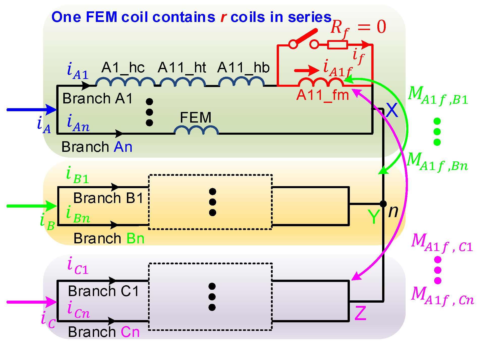
Figure 1. Circuit schematic of the studied SPM wind generators under an ITSC fault.
Energies 16 04723 g001
Figure 2. Cross-sectional view of the studied SPM wind generators with distributed single layer winding configuration.
Energies 16 04723 g002
Figure 3. A FE model of the studied SPM wind generators with the ITSC fault for inductance calculation.
Energies 16 04723 g003
Figure 4. Characteristics of inductances between No. A1 branch and other branches for the 500 kW SPM machine. (a) Analytical results, (b) FE results and (c) Relative errors between analytical and FE results.
Energies 16 04723 g004
Figure 5. Current in the faulty coil of the 3 MW SPM machine before and after a one-coil short-circuit fault.
Energies 16 04723 g005
Figure 6. Steady-state branch currents of (a) phase A and (b) phase C in the 3 MW SPM machine before and after the one-coil short-circuit fault. (Waveforms in the two time intervals 2.4 to 2.5 s and 3.8 to 4 s have been combined.)
Energies 16 04723 g006
Figure 7. Steady-state (a) d-axis and (b) q-axis currents of the 3 MW SPM machine before and after the one-coil short-circuit fault. (Waveforms in the two time intervals 2.4 to 2.5 s and 3.8 to 4 s have been combined.)
Energies 16 04723 g007
Figure 8. Normalized short-circuit current vs coil faulty turns ratio for different power-rating SPM machines using nonlinear inductances.
Energies 16 04723 g008
Figure 9. Normalized single-turn short-circuit current vs relative fault location for different power-rating SPM machines using nonlinear inductances.
Energies 16 04723 g009
Table 1. Key parameters of the studied SPM machines [28,30].
Rated power3 kW500 kW3 MW
Rated speed (rpm)1703215
Rated voltage (Vrms)690690690
Phase current (Arms)2.5438.22790
Series-parallel winding16S1P *7S7P *4S20P *
Series turns/coil522314
Numbers of slots/poles96/32294/98480/160
Rotor outer diameter (mm)426.42195.55000
Stack length (mm)1105501200
Airgap length (mm)22.155
*: rSnP such as 16S1P is used to represent the series-parallel winding configuration of the studied machines. It means r coils in series, n parallel branches.
Disclaimer/Publisher’s Note: The statements, opinions and data contained in all publications are solely those of the individual author(s) and contributor(s) and not of MDPI and/or the editor(s). MDPI and/or the editor(s) disclaim responsibility for any injury to people or property resulting from any ideas, methods, instructions or products referred to in the content.