1. Introduction
The increasing usage of renewable energy sources (RES) in the power system has raised concerns regarding its safe and stable operation. Most of this type of generation is connected to the system via small, distributed generation units, which are linked to the grid through voltage source converters (VSC). However, large-scale generation units, particularly photovoltaic and wind turbines, are becoming more prevalent in the energy market [
1]. Due to their non-inertial nature, these energy sources do not contribute naturally to the system’s angular and frequency stability, which can result in instability scenarios and blackouts. To address this, grid-forming (GFM) controls have been proposed for the VSC so that these energy sources, which are connected to the system by electronic converters, can also contribute to the system’s stability by providing virtual inertia.
The GFM converter is characterized as a converter that is controlled in a way where its behavior is similar to that of a voltage source with low output impedance. Power control is accomplished by emulating the synchronization principle of a real synchronous machine [
2]. A GFM control based on the direct emulation of the synchronous machine model is called a virtual synchronous generator (VSG). This can be realized through the application of high-order models, including a model of the electromagnetic behavior of the machine windings, as well as through low-order models, which apply only the swing equation for synchronization control and an external loop for voltage control [
3,
4,
5].
Several authors have recently studied the transient stability of the system in the presence of these converters. As RES participation increases, and the system’s equivalent inertia decreases, the system’s stability margin for large disturbances (such as three-phase short circuits) eventually reduces. This leads to increased vulnerability to collapse due to an imbalance between instantaneous generation and demand. Additionally, the VSG, which has a GFM characteristic based on a voltage source with low output impedance, can produce high-magnitude fault currents that may damage the converter during voltage sag or short circuit situations [
2]. Recent studies have demonstrated the contribution of VSGs to the power system’s transient angular stability. For example, in [
6], the Lyapunov direct method is used to investigate the transient stability of VSGs, while the effect of the model parameters of a low-order VSG on stability is analyzed. In [
7], the transient stability of multiple GFM schemes, including the VSG, is examined, and design rules are proposed to enhance transient stability. The stability of paralleled VSGs in islanded microgrids is analyzed in [
8]. In [
9], adaptive control is proposed to improve the transient stability of a high-order VSG. Furthermore, several proposals have been discussed to improve the VSG’s fault ride through (FRT). For instance, current saturation of the proportional integral (PI) controllers of the cascaded control loops [
10], virtual impedances to limit the converter reference voltage [
11], directly limiting the reference voltage in the GFM control structure [
12], and FRT enhancement via a model predictive control (MPC) [
13] are some of the main solutions proposed.
The current limitation of VSCs through a virtual impedance loop is discussed in [
14,
15,
16]. The proposed methods for fault current limiting through virtual impedance involve the use of additional loops in the control scheme of distributed generation (DG) inverters. This technique effectively suppresses fault current and subsequent oscillations during faults as well as in the post-fault restoration process. The application of this fault current limitation strategy is specifically considered for the VSG in [
17,
18,
19]. In [
18], the authors proposed a dynamic virtual impedance (DVI) to provide damping torque for a low-order VSG. The DVI aims to emulate the transient and subtransient reactance’s ability to provide damping and, consequently, to reduce the high damping coefficient normally used in low-order VSGs. A virtual resistance is considered for synchronous resonance damping in reference [
17], but the negative effect of the virtual resistance on the transient stability is also mentioned. Increasing the resistance value can improve system stability by reducing power oscillations, but it may also result in increased losses and reduced efficiency [
11]. On the other hand, a higher reactance value can enhance voltage regulation and reduce harmonic distortion, as mentioned in [
11]. In [
19], the authors presented design rules and different control strategies to optimize the output impedance of a VSG to improve fault current and large-disturbance stability. In [
20], the authors propose a strategy based on virtual impedance to improve the low-voltage ride through of a low-order model VSG, aiming to regulate the current of the VSG under transient and steady-state conditions.
The strategies proposed and discussed earlier are based on additional control loops to adaptively adjust the value of virtual resistance and reactance at the output of the converter. This article proposes the use of a VSG implemented using a high-order model, with algebraic equations that also model the electrical part of a synchronous generator (SG). The high-order model provides equations for calculating the armature voltage of the virtual generator with its output impedance. The novelty of this work lies in the adjustment of the virtual armature resistance directly in the high-order model to limit the current during faults. This reduces the complexity of the control by not having an extra control loop to reshape the converter output impedance. The resistance variation is performed only during system faults, while in steady-state operation, the VSG operates with its original value for the armature resistance parameter. The resistance variation was adopted instead of reactance due to its direct relationship with the damping of power oscillations in the system, as described in [
11]. By increasing the armature resistance, the VSG can provide more damping to the grid, which can help maintain the stability of the system during faults. An algorithm is designed to detect fault conditions, such as voltage sag and overcurrent, and the virtual resistance variation is implemented accordingly. As a result, the added resistance effectively limits the current during and after the fault, aiding in returning to steady-state operation.
The article is organized as follows: the structure of the implemented VSG is presented in
Section 2.
Section 3 presents in detail the current limiting strategy applied to the VSG presented in
Section 2.
Section 4 presents the system used for validation and discusses the results obtained in a hardware-in-the-loop (HIL) simulation platform. Finally,
Section 5 is dedicated to the conclusions.
2. The High-Order Virtual Synchronous Generator
The VSG, which is a control mechanism that imitates the behavior of an SG, is controlled by a mathematical model of the SG. This model consists of a set of differential and algebraic equations, and its order and complexity depend on the number of differential equations used. It is common in VSG topologies to use a low-order model, as described in the literature. In this case, only the machine swing equation is employed to control the inverter synchronization, while an external loop regulates the output voltage [
3,
4]. This article proposes the development of a VSG using a third-order machine model, which includes the swing equation as a second-order differential equation, as well as a differential equation corresponding to the quadrature-axis transient voltage [
21]. The swing equation is decomposed and presented in Equations (1) and (2) [
21]:
where
and
are mechanical and electrical powers, respectively,
is the mechanical speed,
is the rotor angle,
is the mechanical damping coefficient,
is the rotor inertia constant, and
is the time in seconds.
The transient voltage equation is shown in Equation (3) [
21]:
where
is the quadrature-axis open circuit transient time constant,
and
are the synchronous reactances in the direct and quadrature axis, respectively,
and
are the transient reactances in the direct and quadrature axis, respectively,
and
are the current components in the direct and quadrature axis, respectively,
is the machine armature resistance,
is the quadrature axis transient voltage, and
is the machine excitation voltage.
The model also has algebraic equations for calculating the electrical power
, presented in Equation (4), and equations for calculating the terminal voltages in the dq frame axis, shown in Equations (5) and (6) as
and
[
21]:
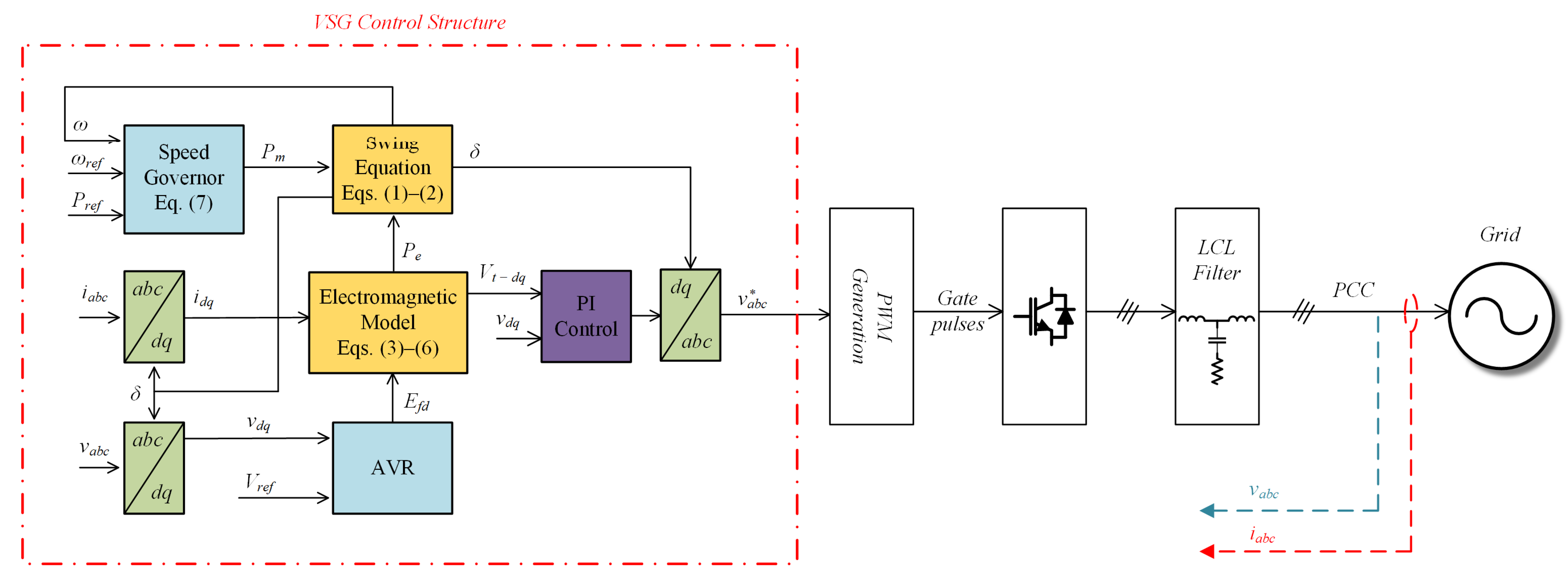
Figure 1 depicts the VSG control structure proposed in this paper. The measured three-phase voltages
and currents
at the point of common coupling (PCC) are transformed to the dq reference frame and fed into the machine model. The active power set-point
, the reference frequency
, and the reference voltage
are all control inputs.
The VSG speed governor is based on a P/f droop control and its characteristic equation is shown in Equation (7) [
21]:
where
is the frequency regulation droop coefficient.
The IEEE DC1A reference excitation system is used as an automatic voltage regulator (AVR) [
22] but with a simplified structure by removing the saturation and voltage transducer. The output terminal voltages calculated in Equations (5) and (6) are the inputs to a double PI control that adjusts the output voltage of the converter. The PI control loop outputs are the pulse-width modulation (PWM) voltage references in the dq frame that are transformed back to three-phase signals (
) before being used in the PWM switching signal generation.
In summary, the yellow blocks in
Figure 1 implement the machine model, while the blue blocks serve as auxiliary controls for adjusting the VSG’s voltage and frequency.
Transient Stability Analysis
Transient stability is a crucial aspect of power systems, as it determines the system’s ability to maintain synchronism in the event of a severe disturbance. The response of the system during such an event is characterized by significant variations in the rotor angles of the generators, which are influenced by the non-linear power–angle relationship [
23]. Although there have been extensive discussions on this type of stability in the literature, a detailed approach is beyond the scope of this work.
In general, several factors determine the transient stability of an SG connected to a system. These factors can be listed didactically when considering a simple grid, such as a single machine infinite bus (SMIB) system. In a three-phase SMIB system, stability analysis using the equal area criterion has shown that the fault CCT is directly related to factors such as generator loading, fault type and location, system reactances, voltage magnitudes in the system, and generator inertia [
24]. The CCT is the maximum duration of a fault before the system reaches an unstable equilibrium point, and its calculation for a SMIB system is shown in Equation (8) [
21]:
where
represents the machine’s critical angle and
the machine’s rotor angle in a pre-fault steady state.
Determining stability in a multi-machine system is more complex, although many of the factors that affect it remain the same. The difference lies in the interaction between the machines and their inertial contributions. To increase the total inertia of a system that experiences a percentage increase in RES compared to the total generation connected to it, a VSG is an option. A virtual inertia system is comprised of RES, short-term energy storage, and converters, which are controlled by a VSG algorithm. The DC-link capacitor stores the kinetic energy, which compensates for it. In this context, the energy stored in the capacitor is equivalent to the virtual rotational energy of the VSG.
However, the VSG proposed for this work and several other structures presented in the literature lack the inherent capacity to protect against fault overcurrent. As a result, the converter is exposed to destructive current levels, and it must be disconnected in these situations to avoid damage. This effectively prohibits the converter’s potential contribution in fault situations. Therefore, it is crucial to suggest alternatives to limit the fault current injection of VSGs to maintain their contribution to system stability.
3. Fault Ride through (FRT) Strategy Based on Virtual Armature Resistance
The main objective of this work is to use an FRT technique to limit the current of high-order VSGs during three-phase faults. The goal is to validate not only the effectiveness of limiting current injection during the fault but also the VSG contribution to the system’s transient stability. This will be investigated by comparing the CCT of the system with and without FRT control in a hybrid grid with a VSG operating in parallel to a conventional SG.
The adopted technique for limiting the fault current will consist of increasing the value of the virtual armature resistance in the high-order VSG model. The modification affects the model’s Equations (5) and (6), which are used to calculate the reference terminal voltage for switching the VSG. To better understand the true effect of adding virtual resistance, one can visualize the model as a voltage source behind impedance, as shown in
Figure 2 in an equivalent circuit representation. In
Figure 2,
and
are the grid impedance parameters,
is the grid voltage,
and
are the VSG armature impedance parameters,
is the VSG transient voltage, and
and
are the VSG output current and voltage, respectively.
The output current of the machine is directly proportional to the impedance of its armature, as shown in
Figure 2 and Equations (5) and (6). The current flowing through the machine windings is limited by increasing the value of
during transient operation. Increasing the virtual resistance parameter has the same effect for limiting the VSG’s current, in this case by lowering the reference voltages generated for switching by Equations (5) and (6). As the output current increases, the voltage sag in the virtual armature circuit increases, lowering the values of
and
.
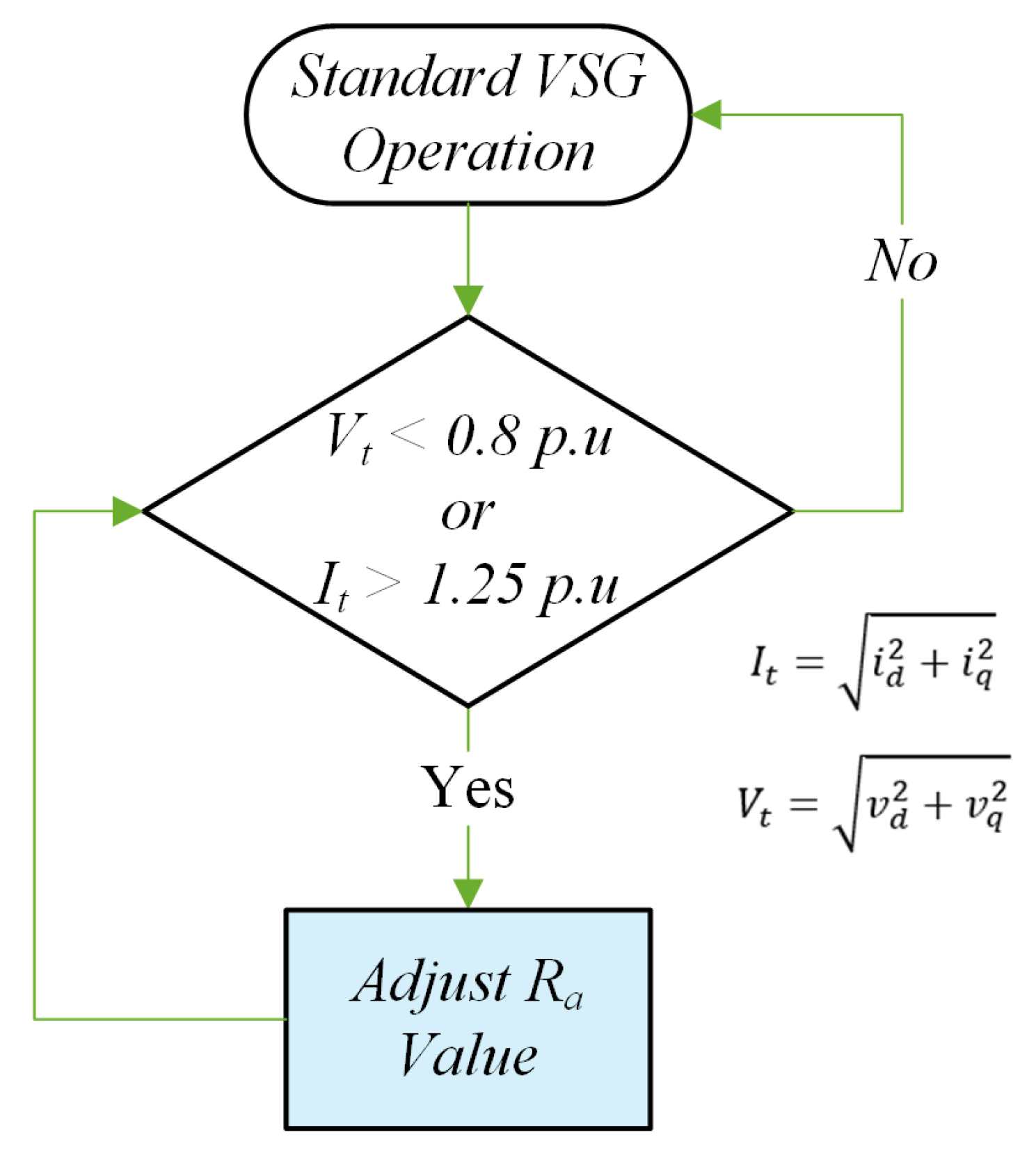
A fault detection algorithm is used to create the proposed virtual resistance variation. The algorithm adds resistance to the model if the voltage
and terminal current
levels of the VSG exceed certain limits. When a fault causes a voltage drop at the VSG terminals, the FRT control increases the resistance to limit the current during the fault. When the fault is cleared, the voltage rises, but the control continues to act in the post-fault period to limit the VSG’s return current. The FRT control resets the resistance value to its nominal value when both sensing parameters return to steady-state levels. Typically, the synchronous machine’s normal armature resistance value is so low that it is ignored. The resistance value used in the FRT strategy is comparable to the reactance in p.u The proposed FRT control algorithm is depicted in the flowchart in
Figure 3.
4. Case Studies
4.1. Case Description
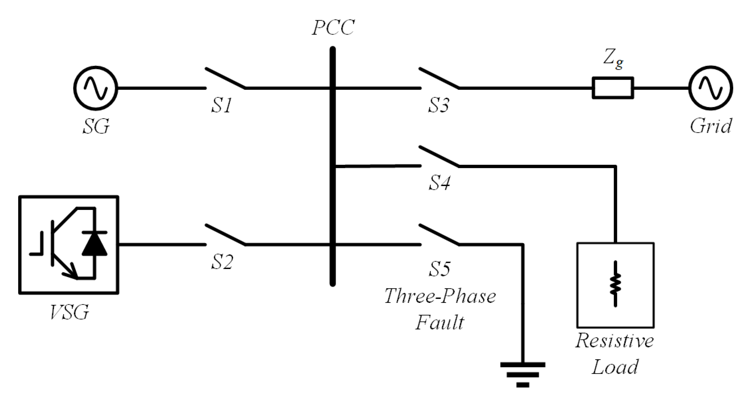
The system shown in
Figure 4 was used to validate the proposed FRT control. The studied VSG is connected in parallel to an SG and a PCC, which is connected to an infinite bus by a line impedance in the system depicted in
Figure 4. The SG’s speed governor and AVR are the same as those used in the VSG.
A three-phase fault is applied to the PCC to evaluate the proposed control. For a VSG islanding test, a constant impedance load is also connected to the PCC. Switches S1 to S5 allow the system to be configured for different scenarios. Using the Typhoon HIL 402 device, the converter and grid/load system will be simulated in real-time in the HIL environment. Texas Instruments’ digital signal processor TMSF28379D was used to implement the VSG control. A Yokogawa ScopeCorder DL350 was used to capture the VSG’s output voltage and current.
Figure 5 depicts the schematics for the test bench used to obtain the results.
Figure 6 shows the HIL test bench with its components in operation.
The TMSF28379D DSP is connected to the Typhoon HIL 402 device via an interface card in charge of routing the analog signals from the simulation to the DSP and the PWM signals from the DSP to the real-time simulation. In this simulation, six analog outputs from the HIL 402 were used for the three-phase voltage and current, while six digital inputs were used to receive the PWM signals generated by the control embedded in the TMSF28379D.
The proposed FRT control’s performance is evaluated using two metrics. The first metric is the control’s ability to limit the VSG current during the fault. The SG and VSG are connected to the PCC along with the infinite bus for this analysis via switches S1, S2, and S3, respectively. The active power set-points on both the VSG and the SG are set to 1.0 p.u Switch S5 is turned on for a set time to apply the fault to the PCC. The VSG output voltage and current curves are then analyzed for different values of virtual resistance added by the FRT control. Then, for a given fixed resistance adjustment, the system CCTs will be checked with and without the action of the FRT on the VSG.
Finally, a VSG islanding test is performed by disconnecting the synchronous generator (S1) and the infinite bus (S3) at the beginning of the fault. In this islanding scenario, the resistive load starts the test connected to the PCC through switch S4. The parameters used to simulate the model in the HIL test bench and the control system are given in
Table A1 of
Appendix A.
4.2. Current Limiting Results
In this case, the system was simulated with switches S1, S2, and S3 turned on. By activating switch S5, a three-phase fault is applied for 200 ms. This case was first simulated without the resistance adjustment to serve as a baseline and then for three different virtual resistance adjustment values: 0.5 p.u, 1.0 p.u, and 1.5 p.u.
The voltage and current graphs obtained are shown in
Figure 7,
Figure 8,
Figure 9 and
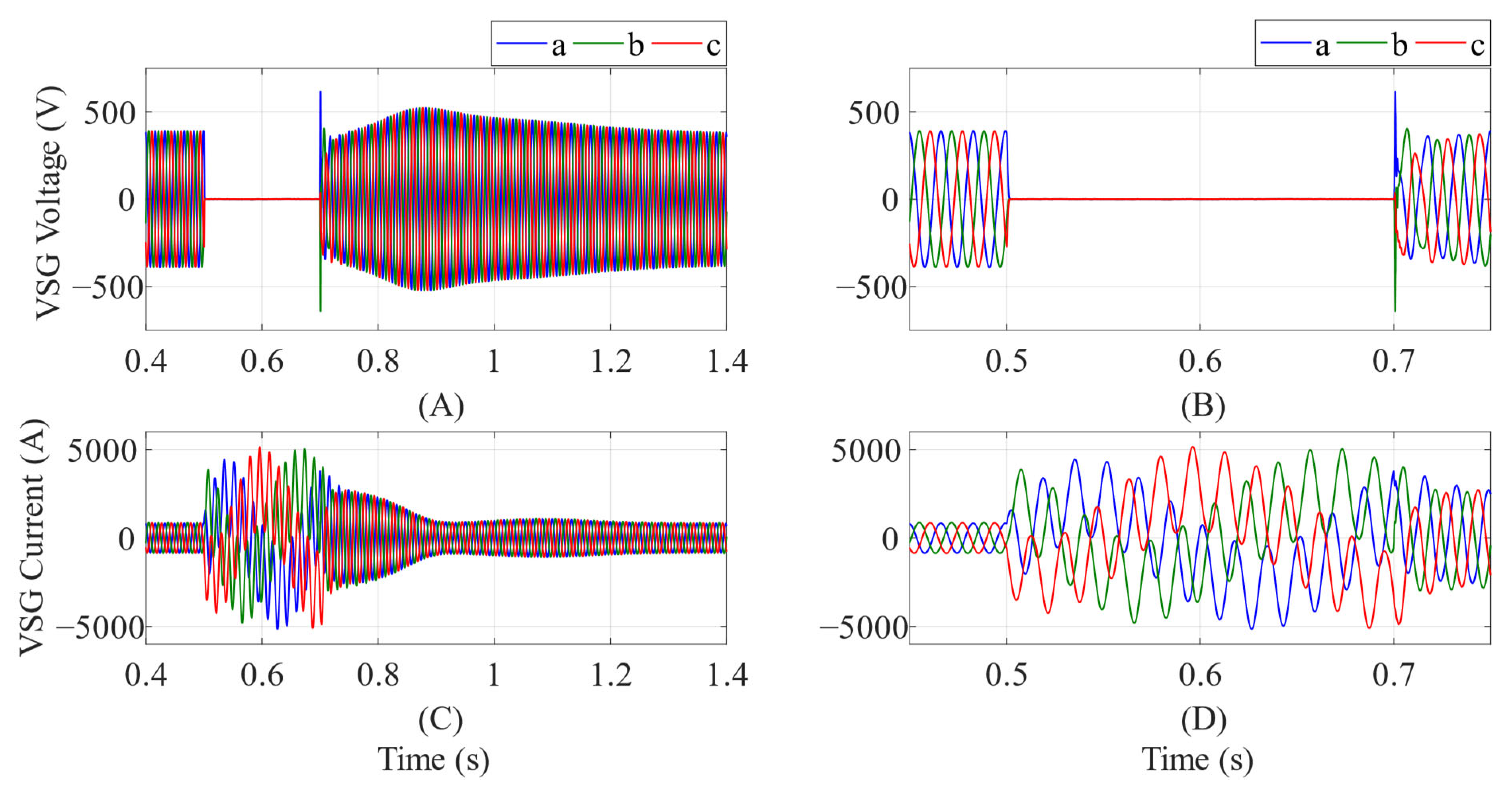
Figure 10. In all figures, subfigure (A) shows the voltage curve of the VSG for 1 s, subfigure (B) shows the voltage curve of the VSG with a zoom for the short-circuit instant from 0.5 s to 0.7 s, the subfigure (C) shows the current curve of the VSG for 1 s, and subfigure (D) shows the voltage curve of the VSG zoomed in for the short-circuit instant from 0.5 s to 0.7 s. The vertical scale for current in all scenarios was kept the same to highlight the control’s current-limiting feature. The fault was applied at 500 ms and cleared at 700 ms.
According to
Figure 7, the VSG peak current exceeds 5.0 kA during the fault and remains high for approximately 200 ms after the disturbance has ended. This maximum current level is more than five times the nominal peak current of the VSG, which was approximately 850 A pre-fault and would undoubtedly damage the inverter if it continued to operate with the fault.
From
Figure 8,
Figure 9 and
Figure 10 the effect of the proposed FRT technique on the VSG current limitation is shown.
Figure 8 shows that boosting the virtual resistance to 0.5 p.u reduces the peak current reached during the fault to 3.3 kA and also lowers the current levels during post-fault recovery. However, at this level, inverter operation is still unsafe. Therefore,
Figure 9 and
Figure 10 present results for higher values of virtual resistance.
Figure 9 shows that the added resistance of 1.0 p.u was able to limit the peak current during the fault to 1.9 kA, resulting in better post-fault recovery behavior. Finally,
Figure 10 depicts the result for a 1.5 p.u added resistance, with a maximum peak current of approximately 1.4 kA, a 64% increase over the VSG’s nominal current. The results show that the proposed FRT control is effective in limiting the increase in VSG current during a three-phase short circuit situation. It is expected that the VSG will be able to remain connected to the grid even in the event of a severe fault, thereby contributing to the stability of the electrical system.
4.3. Critical Clearing Time Results
In this case, it was determined whether the VSG continues to contribute to the system’s transient stability despite the presence of the FRT control limiting its fault current. The system was first simulated without the FRT control for reference and then with the proposed control included. For this, the resistance added to the model by the FRT control was fixed at 1.5 p.u., and the same scenario as in the previous case was simulated by varying the fault time until finding the CCT or finding the maximum fault time before the system reaches instability. The loading of the VSG and the SG was also changed through their set-points for a more comprehensive analysis. The VSG power was varied between 0.0 p.u and 1.0 p.u., and the power of the SG was varied between 0.2 p.u and 1.0 p.u., both in 0.2 p.u increments, to create a set of 60 simulation scenarios with 30 for each condition (with and without FRT control).
Table 1 and
Table 2 show the CCT results obtained. The reference CCTs of the SG operating alone can be obtained from scenarios with the VSG’s power set to zero.
For a graphical representation of the results, surface planes were plotted with the generator’s powers on the
x and
y-axis and the CCT on the
z-axis.
Figure 11 shows the planes.
It is possible to see that the CCT increases in all scenarios, with or without the FRT control in the VSG turned on. In other words, the VSG always contributes to increasing the CCT and, thus, the system’s transient stability margin. This demonstrates that the proposed FRT control not only limits the VSG fault currents to safe levels, but it also maintains its inertial contribution to the system even when the fault is active. However, the results show that the performance of the proposed FRT control affects this contribution. This behavior is to be expected, especially given the change in VSG behavior during the post-fault recovery period. The presence of a virtual resistance in the armature circuit alters the characteristic of the synchronous machine’s power-angle curve after fault clearing, resulting in this change in the stability margin. The only exception to this rule is when the VSG loading exceeds the SG. This effect is visible on the surfaces of
Figure 11 when the blue plane representing the scenario with the FRT control has higher CCT values in some scenarios where the power delivered by the VSG is greater than the power delivered by the SG.
The CCT was determined by repeating the simulations with different fault times until the characteristic of power oscillation indicative of transient instability was confirmed, as shown in
Figure 12 and
Figure 13. In all figures, subfigure (A) shows the voltage curve of the VSG for 1 s, subfigure (B) shows the voltage curve of the VSG with a zoom for the short-circuit instant from 0.5 s to 0.85 s, the subfigure (C) shows the current curve of the VSG for 1 s, and subfigure (D) shows the voltage curve of the VSG zoomed in for the short-circuit instant from 0.5 s to 0.85 s.
Figure 12 and
Figure 13 show simulations in which the generator and the VSG were at maximum load and for a fault extinction time of 350 ms. In both scenarios, it is possible to observe that the transient instability presents itself through post-fault power swings with or without FRT control.
4.4. Islanding Scenario
In all previous cases, the synchronous generator and the grid remained connected to the PCC during a fault so that an individual analysis of the VSG’s behavior could be performed. However, this is not a realistic operating scenario. In a real-world power system, carefully programmed protection elements would isolate the fault and protect the generator and feeder. A VSG without overcurrent protection, such as an FRT control strategy, would invariably be disconnected from the PCC, causing loads connected to the same PCC to lose power.
This final simulation case aims to demonstrate that the high-order VSG, in conjunction with the proposed FRT control, can survive the fault applied in the PCC and smoothly transition to island mode operation. The system is simulated with all switches turned on except the fault switch. A fault is applied by turning switch S5 on for 200 ms, and after 30 ms switches S1 and S3 are opened. The scenario is simulated for the VSG with and without the proposed FRT control. The results are shown in
Figure 14 and
Figure 15. In
Figure 14, subfigure (A) shows the voltage curve of the VSG for 1.6 s, subfigure (B) shows the voltage curve of the VSG with a zoom for the short-circuit instant from 0.5 s to 0.7 s, the subfigure (C) shows the current curve of the VSG for 1.6 s, and subfigure (D) shows the voltage curve of the VSG zoomed in for the short-circuit instant from 0.5 s to 0.7 s. In
Figure 15, subfigures (A) and (C) shows the voltage and current for 2.6 s while subfigures (B) and (D) shows the same time period as the subfigures (B) and (D) from
Figure 14.
After the fault is extinguished, the VSG could operate in island mode and feed the 300-kW load in both scenarios. However, without FRT control, the VSG is subject to high fault currents as shown in
Figure 14, which would prevent it from operating.
As illustrated in
Figure 15, the FRT control limits inverter current to safe levels and enables a smooth transition to an island operation mode.
5. Conclusions
This paper proposes a fault current limiting technique that adjusts the virtual armature resistance of high-order VSGs to improve their FRT ability. The aim of limiting the VSG’s fault current is to preserve its inertial contribution to the system’s transient angular stability. The primary contribution of this article lies in the way the adjustment control of virtual resistance was performed. The change is directly applied to the armature resistance parameter, which is an integral part of the synchronous machine model used to implement the VSG. Consequently, this adjustment does not increase the complexity of the VSG, as it eliminates the need for a separate control loop dedicated to the virtual impedance.
To evaluate the effectiveness of the proposed system, real-time simulations in hardware-in-the-loop were carried out. During a three-phase fault, the results demonstrated that increasing the resistance value led to a decrease in current until hitting diminishing returns. Without the proposed resistance adjustment, the peak value of the transient current reaches levels above 5 kA. By adjusting the resistance to 1.5 p.u, it was possible to limit the current to 1.4 kA, showing that the proposed control works. The CCT results show a reduction compared to the scenario without fault current limitation. For example, for the SG and VSG injecting 1.0 p.u of active power to the grid, the CCT without virtual resistance adjustment is 298 ms, while for the scenario with the proposed resistance adjustment the CCT is reduced to 285 ms. However, this CCT is still higher when compared to the case where only the SG is connected and operating with 1.0 p.u of power, which in this case is 253 ms. The results demonstrate the method’s effectiveness in reducing the VSG’s current during and after the fault’s extinction in the PCC while maintaining its contribution to the system’s transient stability with the presence of FRT control, albeit naturally diminished.
In an islanding scenario, the SG and grid are disconnected, leaving only the VSG to supply power to an active load after the fault. The proposed technique proves its ability to limit the islanding current transient by reducing it from 4 kA to 1.6 kA and smoothly transitioning the VSG to the island operating mode.


