Abstract
During the cold-start process of a PEMFC, the supply of air and hydrogen in the gas supply system has a great influence on the cold-start performance. The cold-start of a PEMFC is a complex nonlinear coupling process, and the traditional control strategy is not sensitive to the real-time characteristics of the system. Inspired by the strong perception and decision-making abilities of deep reinforcement learning, this paper proposes a cold-start control strategy for a gas supply system based on the MADDPG algorithm, and designs an air supply controller and a hydrogen supply controller based on this algorithm. The proposed strategy can optimize the control parameters of the gas supply system in real time according to the temperature rise rate of the stack during the cold-start process, the fluctuation of the OER, and the voltage output characteristics. After the strategy is trained offline according to the designed reward function, the detailed in-loop simulation experiment results are given and compared with the traditional control strategy for the gas supply system. From the results, it can be seen that the proposed MADDPG control strategy has a more effective coordination control effect.
1. Introduction
With the development of the new energy vehicle industry, PEMFC (Proton Exchange Membrane Fuel Cell) vehicles have gradually become the focus of major companies and researchers. Among the many fuel cells developed, the PEMFC has become one of the most suitable energy sources for new energy vehicles due to its high energy conversion rate, clean and environmentally friendly reaction products, and low operating temperature [1].
Despite the numerous advantages and wide applications of the PEMFC, however, it has not yet been fully commercialized and widely used in people’s daily lives. One of the main obstacles to the wide application of the PEMFC is the cold-start problem [2]. The cold-start process of the PEMFC, as the name suggests, refers to the process in which the PEMFC starts in a low temperature environment (usually below −10 °C) and the temperature of the stack gradually increases to above 0 °C. In the electrochemical reaction of the PEMFC, water is produced as the reaction product. However, in low temperature environments, water tends to condense into ice, which can hinder the gas diffusion layer and cover the catalyst layer, reducing the reaction activation area. Consequently, the electrochemical reaction may be interrupted, and the cold-start of the PEMFC may fail if the stack temperature does not reach 0 °C before the reaction activation area drops to 0 [3]. Therefore, to ensure the success of the PEMFC cold-start, the stack temperature must reach 0 °C before the electrochemical reaction stops.
In order to improve the cold-start performance of the PEMFC, many researchers around the world have conducted a great deal of relevant research. At present, the common cold-start strategies, including shutdown purge, electric heating, cooling water heating and other methods, are widely used. In recent years, some scientists have tried to make a breakthrough in materials. Due to the high latent heat storage capacity of phase change materials [4], Sasmito et al. [5] used them as a heat storage medium for the PEMFC and significantly improved the cold-start performance. In their study on electrical heating strategies, Li et al. [6] chose a heatable insulation material that encased the stack and preheated it before the cold-start process, which greatly improved the cold-start success rate, but also significantly increased the cold-start time. Li et al. [7] proposed inserting an electric heating wire into the cathode plate for local heating, which can also effectively improve the cold-start performance.
Although there have been many advances in cold-start research in recent years, most studies still focus on external heating methods. However, adding additional heating devices not only increases the volume, weight, and cost of the PEMFC, but also reduces the energy efficiency. Therefore, research on internal self-heating methods for the PEMFC is of great importance. Currently, there are three main types of self-heating strategies: (1) controlling the current density or voltage to heat the stack [8]; (2) reactant starvation method [9]; and (3) using mixtures of O/H, methanol, or ethanol to increase the stack temperature [10]. However, the improvement of the PEMFC cold-start performance by these methods is still limited, so further research on the PEMFC self-heating control strategies is essential. Since the operation of the PEMFC is a nonlinear coupled process with multiple inputs and outputs, which includes hydrogen and air supply, water and thermal management, temperature and humidity management, and is also affected by the hydrogen purging effect in the stack during the cold-start process, how to coordinate and control the factors affecting the cold-start performance of the PEMFC is a major challenge. In previous studies, researchers have developed many control methods:
- (1)
- Linear control methods: linear control methods have been developed for many years. Earlier methods included quadratic Gaussian controllers and multivariate quadratic controllers and, more recently linear parametric control methods have been developed. However, these methods have many drawbacks, so researchers have gradually turned to the study of nonlinear control methods [11].
- (2)
- Model-based control methods: model-based control methods can comprehensively simulate the controlled system, such as state-space predictive control methods. However, these methods have a limited scope because they cannot be used for nonlinear systems [12].
- (3)
- Adaptive control methods: adaptive control methods are characterized by high robustness and real-time performance and are widely used in control domain development. Recent research includes data-oriented adaptive control methods, parameter identification-based adaptive control methods, etc. [13].
- (4)
- PID control methods: various PID controllers have been developed, including neural network PID controllers, fuzzy PID controllers, etc. Due to their excellent robustness and real-time feedback performance, they have become a mainstream technology in the field of control engineering [14].
Although various control strategies for the PEMFC have been developed over the years, most of them are not sensitive to operating conditions. In recent years, many researchers have applied the neural network method in PEMFC research in areas such as energy management, remaining life prediction, and fault diagnosis. This method can sensitively reflect the operating condition of the stack and, thus, greatly improve the control effect. In the field of the PEMFC’s remaining lifetime prediction, Safa et al. [15] used a stacked autoencoder to obtain PEMFC degradation data online and predict the remaining lifetime in real time, with a prediction accuracy of over 90%. Ma et al. [16] first proposed the use of long short-term memory networks (LSTM) to predict the remaining lifetime of PEMFCs in order to solve the problems of gradient explosion and disappearance that occur when RNNs process PEMFC data. They conducted experiments with three different PEMFCs and eight different operating conditions, and the verification experiments showed that the remaining lifetime prediction was improved to different degrees under each operating condition. Based on the research of Ma et al., Zuo et al. [17] reduced the prediction error of the remaining lifetime of PEMFCs by improving the neural network model. In the field of PEMFC performance optimization, there have been remarkable research results in recent years. Khajeh-Hosseini-Dalasm et al. [18] combined neural networks with statistical methods for predicting and analyzing the performance of PEMFC catalyst layers for the first time and obtained optimal performance by analyzing the sensitivity factors of structural parameters through mean deviation and variance analysis of the trained data. Huo et al. [19] predicted the polarization curve of PEMFC membrane electrodes according to training data by optimizing the convolutional neural network (CNN) algorithm, which can reduce unnecessary experiments in the development of MEA. Yan et al. [20] used the bagging ensemble learning method to integrate the neural network model and constructed a new method for predicting PEMFC performance which achieved high prediction accuracy even with limited training data.
Reinforcement learning has been an important research direction in the field of artificial intelligence in recent years and has attracted the attention of many engineers. Unlike using neural networks as a data-processing tool, reinforcement learning can learn and optimize control strategies directly from data. The core idea of the algorithm comes from behaviorist psychology. The intelligent agent explores the external environment, updates its strategy based on feedback signals, and achieves the maximum cumulative reward, realizing model-free and end-to-end control, thus demonstrating its unique advantages in the control domain. Deep reinforcement learning combines the powerful perceptual capability of deep learning with the excellent decision-making capability of reinforcement learning, which can solve many complex and coupled environmental problems. In the field of PEMFC research, Lin et al. [21] proposed a data-driven neural controller with an automatic adaptive system based on the health state to study faults such as PEMFC channel overflow and membrane desiccation. Khadhraoui et al. [22] developed an energy management model for PEMFC vehicles and used reinforcement learning algorithms to optimize the efficiency of PEMFC vehicles in real time under operating conditions to significantly reduce hydrogen consumption per hundred kilometers of the vehicle while optimizing efficiency.
During the cold-start process of the PEMFC, much of the energy needed to warm up the cell is provided by the heat released during the internal electrochemical reactions. The PEMFC is a highly coupled and complex system, and the electrochemical reactions during the cold-start process are affected by various factors, such as the inflow velocity and humidity of the gas supply system and the ambient temperature. Therefore, the PEMFC is very sensitive to the operating conditions of the system, especially the gas supply, during the cold-start process. However, controlling the operating conditions in such a complex system is challenging, and the conventional adaptive control methods and PID control methods have their limitations in PEMFC control. To improve the control performance of the PEMFC during the cold-start process, this paper proposes a cold-start control strategy for the gas supply system based on the Multi-Agent Deep Deterministic Policy Gradient (MADDPG) algorithm. The DDPG algorithm is considered a non-model method due to its fast response and precise control capabilities, and has been extensively researched in recent years [23,24]. Unlike traditional control methods, DDPG integrates both deep learning and reinforcement learning capabilities and is able to develop a strategy by interacting sufficiently with the environment without having to adapt the model to a nonlinear system [25,26]. During the cold-start process, the inflow rates of the anode and cathode affect each other and interact, and DDPG cannot effectively control both operating conditions. Therefore, in this study, based on DDPG, the MADDPG algorithm is used to simultaneously control the oxygen and hydrogen inflow rates, and designs an air supply controller and a hydrogen supply controller based on MADDPG. The research results show that the air supply system controller improved by MADDPG is more sensitive to the real-time state of the stack and can effectively reduce the probability of stack startup failure.
The innovations of this paper are as follows:
- (1)
- Unlike traditional PEMFC gas supply system control strategies, this paper presents a control strategy based on the MADDPG algorithm and designs corresponding air and hydrogen supply controllers. As a gas supply system control strategy, MADDPG provides feedback on various stack states during the PEMFC cold-start process and optimizes the gas supply system operating parameters in real time, effectively improving the PEMFC cold-start performance.
- (2)
- This study is the first to apply Deep Reinforcement Learning to the PEMFC cold-start research. It improves the control method of such a complex coupled nonlinear system in PEMFC cold-start and opens new avenues for research in this field.
2. PEMFC Cold-Start Model
2.1. Framework of the Model
This study was performed by simulation experiments. Therefore, a three-dimensional multiphysics simulation model based on the cold-start mechanism of PEMFC was established in COMSOL Multiphysics 6.0 numerical simulation software.
The whole model includes a PEMFC stack, an air compressor, a hydrogen storage tank, a controller, a humidifier, a radiator, and a load. The schematic diagram of the model can be seen in Figure 1.
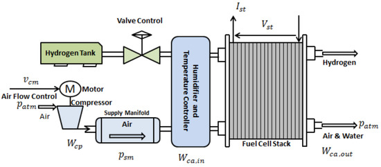
Figure 1.
Schematic diagram of cold-start system for the PEMFC.
The system’s working principle is as follows:
During the cold-start of the PEMFC, the load is supplied with a constant current while the air compressor compresses the air. The compressed air flows into the cathode of the stack and the hydrogen from the storage tank flows through the humidifier into the anode of the stack. After internal transfer, the hydrogen decomposes into hydrogen ions as it passes through the proton exchange membrane and reacts with the air in the cathode to form water, releasing the heat of reaction and gradually increasing the temperature of the stack.
To validate the effectiveness of the established three-dimensional COMSOL model, this study conducted mesh validation and solution algorithm settings for the model, with specific details as follows:
- (1)
- Mesh validation
We employed a three-dimensional, unstructured mesh consisting of tetrahedral elements due to its ability to capture complex geometries and boundary layer features. The initial mesh was generated with a focus on the key regions, such as the gas diffusion layers (GDLs), catalyst layers (CLs), and proton exchange membrane (PEM), where the physical and chemical processes are intricate. We locally refined the mesh in these areas to achieve higher accuracy in the simulation results.
To verify the mesh independence, we conducted simulations using three different mesh sizes: coarse, medium, and fine. The total number of elements for each mesh configuration was 1.5 million, 3 million, and 6 million, respectively. We compared the output results, such as current density and cell voltage, and observed that the differences between the medium and fine mesh simulations were less than 1%, indicating that the mesh was sufficiently refined. Consequently, we selected the medium mesh for our subsequent simulations to balance computational cost and accuracy.
- (2)
- Solution algorithm settings
The PEMFC model involves the coupling of multiple physics, including electric current transport, gas diffusion, and proton conduction. Thus, we employed an iterative solver, specifically the Generalized Minimal Residual (GMRES) method, to address the nonlinear problems.
For the nonlinear solver, we adjusted the Newton’s method convergence criteria, setting the relative tolerance to and the maximum number of iterations to 50. Additionally, we utilized an incomplete LU (ILU) preconditioner for the linear solver to improve the solution speed.
In the case of transient simulations, we adopted the Backward Differentiation Formula (BDF) adaptive time-stepping method. We set the initial time step to s, with a minimum of and a maximum of . The BDF method helped us to balance the solution accuracy and computational time by automatically adjusting the time step based on the solution’s temporal behavior.
By optimizing the mesh validation and solution algorithm settings, we ensured accurate and reliable results for our PEMFC model in COMSOL Multiphysics. Moreover, model validation was performed in this study based on the experimental conditions reported in reference [27], using the same model size parameters. The specific cold-start model parameters are listed in Table 1. During the validation process, simulations were performed under three different operating conditions with current densities of , respectively. The validation results are shown in Figure 2.

Table 1.
Geometric structure and size parameters of the PEMFC cold-start system.
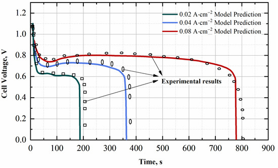
Figure 2.
The validation results of the PEMFC cold-start model.
From Figure 2, it can be seen that the fuel cell stack voltage fluctuations simulated by the model under different operating conditions agree well with the experimental results. This shows that the developed model can effectively simulate the actual process of cold-start of a PEMFC.
2.2. Assumptions
- (1)
- All gases are considered ideal.
- (2)
- Water produced by electrochemical reactions initially exists as membrane-bound water.
- (3)
- Heat and mass transfer in the direction of stack thickness are neglected, with diffusion being the primary transfer mode.
- (4)
- Changes in internal pressure of the stack are ignored.
- (5)
- Gravity effects are not considered.
- (6)
- Ice formed by saturation of membrane-bound water in the cathode and anode catalyst layers is entirely present in the pores.
- (7)
- The physical parameters of each layer are concentrated at the center position of each layer.
2.3. Boundary Conditions
2.3.1. Electromotive Force Boundary Condition
In this study, the following assumptions are made:
- (1)
- The initial inlet gas is dry gas;
- (2)
- The initial voltage is
- (3)
- The initial water content in the electrolyte membrane and catalyst layer is .
Considering the activation loss of the stack during the cold-start process, the potential of the cathode and the anode can be defined as follows:
where is reversible voltage, is cell voltage, and is total voltage loss. Additionally, reversible voltage can be expressed as:
where are the inlet partial pressures of hydrogen and oxygen, respectively, and is the operating temperature.
2.3.2. Mass Boundary Condition
The mass flow rates at the anode and cathode of the stack can be defined as:
where , are the average density of the inlet gas mixture at the anode and cathode. , are the stoichiometric ratios at the anode and cathode; is the reference current density; is the effective surface area of the catalyst layer (CL); is Faraday’s constant; , are the molar concentrations of hydrogen and oxygen; represent the molar mass of hydrogen and oxygen; , are the relative humidity at the anode and cathode; is the saturation pressure; is the gas constant; and , are the inlet temperatures at the anode and the cathode.
2.3.3. Heat Transfer Boundary Conditions
At standard atmospheric pressure, the heat transfer rate between the PEMFC and the external environment can be expressed as follows:
where is the heat transfer coefficient at the outer surface of the cell; is the surface area of the outer surface of the cell; is the surrounding temperature; and is the temperature at the outer surface of the cell.
3. Control Strategy of Gas Supply System Based on MADDPG
3.1. Deep Reinforcement Learning
Deep Reinforcement Learning (DRL) is a model-free end-to-end perception and control system that combines the strong perception capabilities of Deep Learning with the strong decision-making capabilities of Reinforcement Learning. The overall learning process can be summarized as follows:
- (1)
- At each successive time step, the agent interacts with the environment and perceives its state features through deep learning.
- (2)
- Based on the expected reward, the value function of the current state and action is evaluated, and the current state is mapped to an action by a certain strategy.
- (3)
- The environment responds to the issued action and proceeds to the next time step.
- (4)
- The above process is repeated in a loop.
3.2. Common DRL Algorithms
3.2.1. Deep Q-Learning Network
The deep q-learning network (DQN) is a commonly used value-based Deep Reinforcement Learning method. It integrates neural networks into the classical Q-learning algorithm, and aims to exploit the powerful adaptability of neural networks to gradually approach the target Q-value through the estimated Q-value that the network outputs [28].
The update method of the algorithm is as follows:
The loss function can be expressed as follows:
3.2.2. Actor-Critic
The principle of the Actor-Critic (AC) algorithm is that the actor generates a set of actions by exploring the environment and then selects an action based on the action probability function; the critic evaluates the actor’s actions; the actor optimizes the action probability function based on the critic’s evaluation and finally guides the agent to select the optimal action [29].
The AC algorithm uses temporal difference error as the evaluation point, and the update method for the actor’s policy function is:
where is the temporal difference error and is the eligibility trace of the state.
The critic updates the network parameters based on the mean squared error between the estimated action value and the actual action value, and the loss function is:
3.2.3. Deep Deterministic Policy Gradient
The DDPG is a deterministic algorithm that combines the ideas of the DQN and AC algorithms. The DDPG algorithm has a network structure consisting of a critic module and an actor module containing four neural networks. The critic module updates the network parameters using the temporal difference error and copies periodically to the target network. The actor module updates the network parameters using the DPG algorithm and selects actions to act on the environment based on the output of its policy network [24].
The update method for the DDPG policy is as follows:
where is the expected return of taking action in state under the policy .
The loss function of DDPG is:
The DDPG algorithm has better stability compared to the DQN and AC algorithms, and is capable of handling continuous action space tasks.
3.3. Controller Design Based on MADDPG
In the cold-start of a PEMFC, the key to successful cold-start is to increase the stack temperature above 0 °C before the stack reaction sites are completely covered with ice. Current research is mainly focused on external heating (i.e., adding auxiliary heaters to the fuel cell system) during the cold-start process. However, the heat released by the electrochemical reactions during the cold-start process is the primary heat source for heating the stack. External heating can only improve the performance of the fuel cell during the cold-start process to a limited extent. Therefore, improving the fuel cell’s self-heating may be more helpful in enhancing its cold-start performance.
During the cold-start process, the intensity of electrochemical reactions is very sensitive to the working environment of the fuel cell. Changes in parameters such as the air and hydrogen flow rates supplied to the fuel cell system, the humidity of the supplied air, and the water content of the membrane can affect the progress of the electrochemical reactions. Therefore, real-time optimization of the PEMFC cold-start operating conditions is particularly important.
This study focuses on optimizing the control strategy of the gas supply system and proposes a MADDPG algorithm that can dynamically adjust the gas supply rate according to the fuel cell condition during the cold-start process. MADDPG is an extension of DDPG in multi-agent tasks, and its basic idea is centralized learning and decentralized execution, which can solve the problem that the traditional DDPG algorithm cannot learn in multi-agent environments [30].
This framework consists of two intelligent controllers—an air supply controller and a hydrogen supply controller—which control the speed of the PEMFC air compressor and the opening of the hydrogen supply valve, respectively. The control diagram is shown in Figure 3.
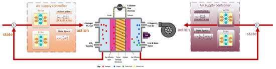
Figure 3.
Controller diagram based on MADDPG.
3.3.1. Air Supply Controller
- (1)
- Oxygen excess ratio
The air supply to the PEMFC directly affects the course of the electrochemical reaction. The excess oxygen ratio (OER) is a parameter that reflects the relationship between the flow rate of cathode oxygen injection and the flow rate of oxygen consumption in the electrochemical reaction, and its formula is as follows:
Studies have shown that too high or too low OER are not conducive to the progress of the electrochemical reaction [31]. Figure 4 shows the optimal OER at different load currents:
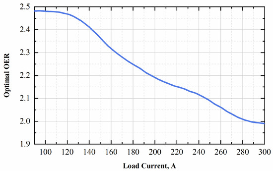
Figure 4.
Optimal OER at different load currents.
Since the air flow consumption is uncertain during the electrochemical reaction at different stages of the cold-start process, the speed of the air compressor must be adjusted to regulate the supplied air flow based on the optimal OER and the variation of the air consumption flow according to the real-time state of the stack.
The cathode oxygen injection flow rate can be expressed as follows:
where is the oxygen injection flow rate, is the mass fraction of oxygen in the air, is the speed of the air compressor, and is the gas inlet flux of the air compressor.
- (2)
- Air supply controller
The air supply controller regulates the air flow into the PEMFC by controlling the voltage of the PEMFC air compressor, the input air contains oxygen, nitrogen, and carbon dioxide. The control interval is 0.1 s, and the control objective is to achieve a higher temperature rise rate and output power for the PEMFC while reducing the hydrogen consumption of the anode.
The action space of the controller is:
State space:
Reward function: The reward function of the air supply controller is related to the operating characteristics of the fuel cell in the current state, including the hydrogen injection flow rate of the anode, the temperature rise rate of the fuel cell, the volume fraction of ice, and the output power:
where are respective weight coefficients; is the temperature rise rate of the stack; is the volume fraction of ice; is the rated power of the stack; and is the flow rate of hydrogen gas injection.
3.3.2. Hydrogen Supply Controller
The hydrogen supply controller regulates the flow of hydrogen into the PEMFC by directly controlling the opening of the valve in the hydrogen storage tube of the PEMFC. The control interval is 0.1 s, and the aim of the control is to achieve a higher temperature rise rate and higher output power of the PEMFC. The hydrogen flow rate can be expressed as follows:
where is the maximum output flow rate of the hydrogen storage tank; is the opening of valve; and is the maximum opening of valve.
The action space can be defined as:
State space:
Reward function: Similar to the air supply controller, the reward function of the hydrogen supply controller is related to the operating characteristics of the fuel cell in the current state, including the fuel cell temperature rise rate, the volume fraction of ice, and the output power:
where are weighting coefficients for their respective terms; is the temperature rise rate of the fuel cell; represents the volume fraction of ice; and is the rated power of the fuel cell.
3.4. Framework of MADDPG Algorithms
The cold-start process of a PEMFC based on the MADDPG control algorithm is a mutually coordinated and influential process. Figure 5 shows the framework of the MADDPG algorithm.
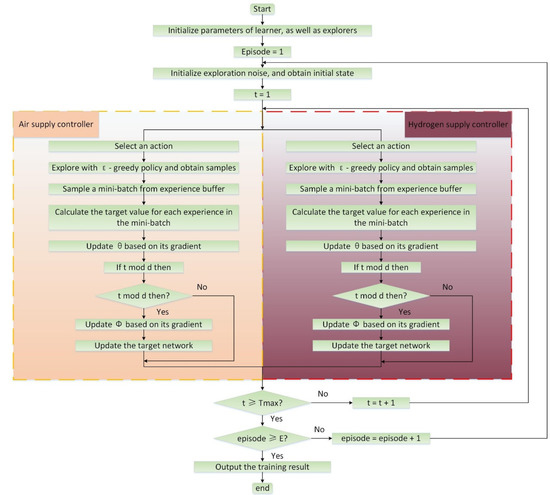
Figure 5.
The framework of the MADDPG algorithm.
From Figure 5, it can be seen that, after the necessary cold-start preparations (such as shutdown purging and auxiliary heating), the cold-start begins. Both the air compressor and the hydrogen storage tank supply the PEMFC with gas in a certain initial state. The anodic hydrogen is decomposed into hydrogen ions which pass through the electrolyte membrane into the cathodic electrochemical reaction zone and react with oxygen. The stack receives external heating heat and electrochemical reaction heat simultaneously, gradually increasing its temperature. The PEMFC sensor simultaneously receives signals for air and hydrogen flow rate, stack temperature, load power, and ice volume fraction, and relays them as current stack state signals to the air supply controller and hydrogen supply controller. The “Actor” and “Critic” neural networks of the two controllers receive the signals and issue actions based on their respective control and reward functions. The air compressor and hydrogen storage tank control systems receive the output action signals and respond to them, resulting in a new set of PEMFC operating characteristic signals. This training process is repeated, continuously improving the control strategy based on the control function and the reward function of the MADDPG algorithm, achieving real-time optimization of the gas supply system during the cold-start process.
The following Algorithm 1 is the pseudocode of the MADDPG control strategy:
| Algorithm 1: Multi-Agent Deep Deterministic Policy Gradient. |
| Initialize critic networks for each agent Initialize actor networks for each agent Initialize target critic networks and target actor networks for each agent Initialize replay buffer for to do Reset environment for to do for to do Observe state Choose action from the Ornstein–Uhlenbeck process Take action and observe reward and next state Store transition in replay buffer end for Sample a random minibatch of transitions from replay buffer for to do Update critic network parameters using: Update actor network parameters using policy gradient: Update target critic and actor networks: end for end for end for |
4. Simulation
4.1. Offline Training
In this study, a combined simulation approach utilizing COMSOL Multiphysics and Simulink is employed during the offline training process. The COMSOL Multiphysics model is utilized to simulate the cold-start procedure of the PEMFC, which serves as a component of the reinforcement learning environment within the Simulink reinforcement learning training framework. Simulink is used to construct the reinforcement learning training framework, which includes components such as air supply controller, hydrogen supply controller, COMSOL Multiphysics reinforcement learning environment, state space, action space, and reward function.
During the cold-start training simulation of the PEMFC, a constant current approach is adopted for the simulation, and the current loading method is as follows:
where is the time of cold-start, and is the current density of constant current loading.
Table 2 gives the parameters adopted in the PEMFC cold-start model.
Table 2.
Parameters of the PEMFC stack model.
In this study, two NVIDIA RTX3090 GPU servers are used for training the MADDPG control algorithm. The related training parameters are listed in Table 3, the maximum number of training rounds is 500, and the training interval for each round is . The simulation software packages are MATLAB/Simulink (R2022a) and COMSOL Multiphysics.
Table 3.
Hyper parameters setting of the MADDPG algorithm.
4.2. Online Application
In order to illustrate the effectiveness of the MADDPG-based algorithm, this study uses the trained MADDPG control strategy (hereafter referred to as Strategy 1) for online simulation, and compares it with the most commonly used PID strategy in the PEMFC control domain (hereafter referred to as Strategy 2).
- (1)
- Strategy 1: In Strategy 1, this study uses air supply and hydrogen supply controllers based on the MADDPG control strategy to control the gas supply system. The specific control methodology can be found in Section 3.4.
- (2)
- Strategy 2: The PID control method used in this strategy is currently the most widely used approach in the PEMFC control domain. It offers advantages such as a simple structure and strong processing capability [32]. The PID control strategy can be modeled as follows:
In this equation, represents the error between the actual value and the reference value ; is the control signal; is the proportional gain for adjusting system accuracy; is the integral gain for eliminating steady-state errors; and is the derivative gain for improving the system’s dynamic characteristics.
During the simulation process of the PID control strategy, an initial control parameter is given, with and . By receiving the state signals fed back from the fuel cell stack, the control parameters are adjusted to achieve real-time control effects.
It is discussed from the following three parts: the first part compares the time required for the successful cold-start of Strategy 1 and Strategy 2 at different starting temperatures; the second part compares the fluctuation of OER in the stack gas supply system under two strategies at a starting temperature of −20 °C; and the third part discusses the changes of stack voltage and ice volume fraction during the cold-start process of Strategy 1 and Strategy 2 at different starting temperatures.
4.2.1. Cold-Start Time
The most direct way to evaluate the cold-start performance of the PEMFC is to evaluate the time required for a successful cold-start. The time required for a successful cold-start is the duration required for the PEMFC temperature to go from the starting temperature to 0 °C. Figure 6 shows the stack temperature rise curves for cold-start with Strategy 1 and Strategy 2 at the starting temperatures of −20 °C and −25 °C, respectively. In Figure 7, the temperature rise rate curves of two different strategies during the cold-start process are shown.
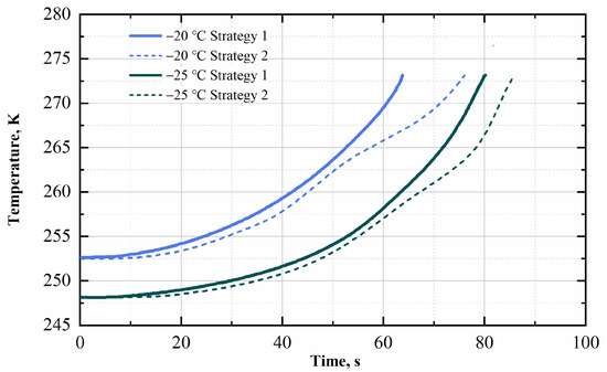
Figure 6.
The temperature of the stack.
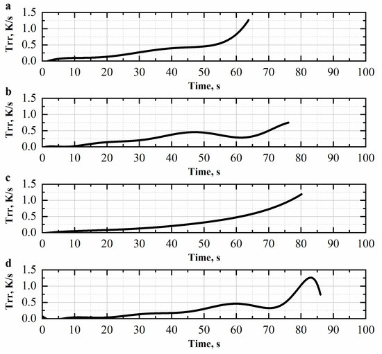
Figure 7.
The temperature rise rate curve of (a) Strategy 1 at the start-up temperature of −20 °C; (b) Strategy 2 at the start-up temperature of −20 °C; (c) Strategy 1 at the start-up temperature of −25 °C; (d) Strategy 2 at the start-up temperature of −25 °C.
From the cold-start temperature rise curve shown in Figure 6, we can intuitively see that—whether Strategy 1 or Strategy 2 is used—starting a cold-start process at a lower temperature requires a longer time for a successful cold-start. This is because, to raise the stack temperature to 0 °C, the lower the starting temperature, the more energy is required for heating and, correspondingly, more time is needed. On the other hand, unlike the conventional PID control strategy, the trained MADDPG control strategy can find suitable gas supply parameters at each stage of the cold-start process, regardless of the starting temperature of −20 °C or −25 °C, so that the stack temperature increases gradually and smoothly. However, due to the poor coordination of the gas supply system in Strategy 2, there are periodic fluctuations in the temperature rise, which is unfavorable for the PEMFC cold-start process. During the whole cold-start process at the same starting temperature, Strategy 1 has a better coordinated control effect compared to Strategy 2. As a result, the stack temperature is always higher with Strategy 1 than with Strategy 2. At the same time, as the cold-start process progresses, the temperature rise rate of the stack also increases, which can be easily seen in Figure 7. However, for the cold-start method with the traditional PID control strategy, the time required for a successful start under the same starting temperature conditions is 6–20% longer than that for the MADDPG control strategy, which intuitively reflects the superiority of the cold-start method with the MADDPG control strategy.
Next, this study investigates the other side of the cold-start temperature rise (temperature rise rate of cold-start).
Figure 7a,b show the temperature rise rate curves of Strategy 1 and Strategy 2 at a starting temperature of −20 °C, while Figure 7c,d show the temperature rise rate curves of Strategy 1 and Strategy 2 at a starting temperature of −25 °C. According to Figure 7, under the two start-up temperatures, the temperature rise rates of Strategy 1 and Strategy 2 have roughly the same trend. The temperature rise rate of Strategy 1 shows a smooth gradual increase because the MADDPG control strategy can always actively find better air supply parameters based on the real-time state feedback of the stack; this allows the electrochemical reactions within the stack to occur in a well-coordinated environment, leading to a more stable reaction process. On the other hand, the temperature rise rate for Strategy 2 exhibits continuous fluctuations, with the amplitude of these fluctuations gradually increasing over time. Although the fluctuations may not seem severe when considering the entire process, and can still result in a gradual increase in the stack temperature, they often hinder the full progression of electrochemical reactions within the stack, ultimately extending the overall cold-start process. Thus, when compared with the temperature rise rate changes observed in Strategy 1, it becomes apparent that the PID control strategy employed in Strategy 2 is unable to effectively adjust the operating parameters of the gas supply system based on the PEMFC cold-start state at each stage.
Overall, the MADDPG control strategy proposed in this study can effectively shorten the time required for cold-start.
4.2.2. OER
During the cold-start process of the PEMFC, the oxygen content in the PEMFC can no longer meet the requirements of the electrochemical reaction due to the low temperature, and the cold-start process of the stack is significantly slowed down at this time. Therefore, the value of OER should be within a reasonable range to ensure the stable and reliable performance of the PEMFC cold-start. A value of OER that is too high or too low may cause the cold-start to fail. The PEMFC reference OER under different load conditions is shown in Figure 4. The following discussion focuses on the changes of OER under Strategy 1 and Strategy 2 in the actual cold-start process.
Figure 8 shows the OER curves during the cold-start process with Strategy 1 and Strategy 2 at a starting temperature of −20 °C.
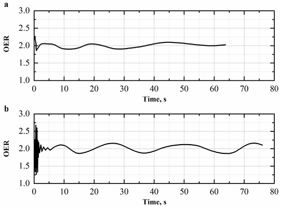
Figure 8.
The OER of (a) Strategy 1 and (b) Strategy 2.
As can be seen in Figure 8a, an initial gas supply system parameter is set at the beginning of a cold-start procedure, and the MADDPG control strategy can quickly stabilize OER within the reference range, avoiding large fluctuations. This shows that the gas supply system can quickly adjust the two gas controllers so that they operate in a coordinated manner based on system feedback, including the stack temperature rise rate and the intake flow rates of the hydrogen or air supply controller. In this range, the electrochemical reactions can be fully carried out during the cold-start process of the PEMFC. In Figure 8b, OER fluctuates significantly at the beginning of the cold-start when using the traditional PID control strategy, and it takes much longer than Strategy 1 for the OER fluctuations to stabilize within a relative amplitude. This indicates that the PID control system requires continuous trial and error after initializing the gas supply parameters to slowly establish a suitable operating condition for the gas supply based on the system feedback. It also shows that the air supply system and the hydrogen supply system cannot work well together during this trial-and-error process.
On the other hand, the amplitudes of OER fluctuations in Strategy 1 are about 50% smaller than those in Strategy 2 when the cold-start process is stable, which shows that Strategy 1 has higher stability.
4.2.3. Voltage and Ice Volume Fraction
During the cold-start process of the PEMFC based on constant current mode, the voltage and ice volume fraction in the stack are important parameters reflecting the state of the stack and the cold-start performance. Under normal circumstances, when the cold-start progresses to a certain stage, the voltage of the stack gradually tends to a stable value, and if the voltage suddenly drops to 0, it means that the electrochemical reaction stops and the cold-start fails. The lower the voltage of the stack, the more likely it is that the cold-start will fail. During the cold-start process, the reaction water produced by the electrochemical reaction continuously condenses into ice. To achieve a successful cold-start, the stack temperature must be increased to above 0 °C before the ice completely covers the electrochemical reaction region. In other words: When the ice volume fraction reaches 1, it means the failure of the cold-start. Therefore, the rate of increase of the ice volume fraction in the stack is also an important parameter reflecting the cold-start state of the stack.
Based on the above theories, Strategy 1 and Strategy 2 are used in this study at a starting temperature of −20 °C and −25 °C, respectively.
The behavior of stress and ice volume fraction during the cold-start process is investigated. The results for the two starting temperatures are shown in Figure 9 and Figure 10.
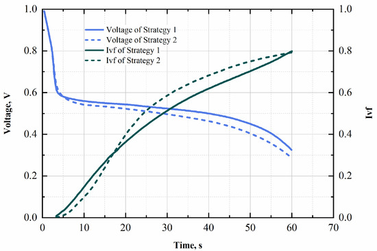
Figure 9.
Voltage and Ivf of stack at start-up temperature of −20 ℃.
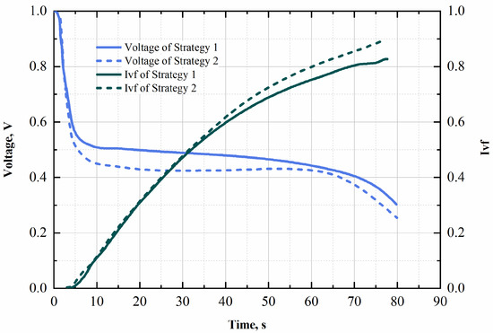
Figure 10.
Voltage and Ivf of stack at start-up temperature of −25 ℃.
From the experimental results in the two environments, in the initial stage of cold-start, the low temperature in the stack causes water to precipitate in the proton exchange membrane, blocking the reaction channel and reducing the supply of reactants, resulting in a sharp drop in the stack voltage. Both Figure 9 and Figure 10 show that the voltage drop is larger for Strategy 2, indicating that Strategy 2 has no obvious feedback on the starting state of the stack in the initial stage of cold-start and fails to increase the hydrogen supply. In contrast, Strategy 1, with its powerful implementation and control capabilities, responds immediately to the lack of reactants in the electrochemical reaction and effectively reduces the voltage drop. When the voltage stabilizes, the stack voltage in Strategy 2 for cold-start remains consistently lower than that in Strategy 1, resulting in a higher probability of cold-start failures.
Regarding the ice volume fraction in the stack, both Strategy 1 and Strategy 2 show a gradually decreasing rate of increase as the cold-start process progresses and the stack temperature increases. However, overall, the ice volume fraction increases faster for Strategy 2 than for Strategy 1. At the end of the cold-start, the ice volume fraction is higher for Strategy 2 than for Strategy 1, reflecting the higher probability of cold-start failure for Strategy 2 compared to Strategy 1.
Combining the above changes in stack voltage and ice volume fraction, it can be concluded that, by using the MADDPG control strategy proposed in this study for cold-start, the probability of cold-start failure is lower than with the traditional PID method.
5. Conclusions
In summary, in this study, the MADDPG algorithm was used to improve the gas supply system of the PEMFC by developing an air supply controller and a hydrogen supply controller. These two controllers can adjust the gas supply parameters in real time according to the temperature rise rate, voltage change, and air and hydrogen flow rates of the PEMFC stack during the cold-start process. The research results show that, compared with conventional PEMFC gas supply system control strategies, the MADDPG-based gas supply system control strategy can significantly improve the cold-start efficiency and effectively reduce the probability of cold-start failure.
Furthermore, this study applies Deep Reinforcement Learning, which is known for its strong perceptual and decision-making capabilities, to PEMFC cold-start research and provides new insights for research in this field. This work demonstrates the potential of advanced machine learning algorithms such as MADDPG in the optimization and control of complex systems such as PEMFCs. Future research can further explore the potential of other deep reinforcement learning algorithms and their applications in various aspects of PEMFC operation and optimization.
Author Contributions
Software, L.P.; Investigation, Y.G.; Resources, T.Z.; Writing—original draft, L.P.; Supervision, T.Z.; Project administration, Y.G. All authors have read and agreed to the published version of the manuscript.
Funding
This research is supported by the National Natural Science Foundation of China (Grant No.22279091).
Data Availability Statement
Not applicable.
Conflicts of Interest
The authors declare no conflict of interest.
Nomenclature
| PEMFC | Proton exchange membrane fuel cell |
| MADDPG | Multi-agent deep deterministic policy gradient |
| DDPG | Deep deterministic policy gradient |
| DQN | Deep q-learning network |
| AC | Actor-Critic |
| PID | Proportional–Integral–Derivative |
| OER | Oxygen excess ratio |
| Ivf | Ice volume fraction |
| GDL | Gas diffusion layer |
| CL | Catalyst layer |
| Trr | Temperature rise rate |
References
- Kim, D.J.; Jo, M.J.; Nam, S.Y. A review of polymer–nanocomposite electrolyte membranes for fuel cell application. J. Ind. Eng. Chem. 2015, 21, 36–52. [Google Scholar] [CrossRef]
- Luo, Y.; Jiao, K. Cold start of proton exchange membrane fuel cell. Prog. Energy Combust. Sci. 2018, 64, 29–61. [Google Scholar] [CrossRef]
- Li, L.; Wang, S.; Yue, L.; Wang, G. Cold-start icing characteristics of proton-exchange membrane fuel cells. Int. J. Hydrogen Energy 2019, 44, 12033–12042. [Google Scholar] [CrossRef]
- Zalba, B.; Marín, J.M.; Cabeza, L.F.; Mehling, H. Review on thermal energy storage with phase change: Materials, heat transfer analysis and applications. Appl. Therm. Eng. 2003, 23, 251–283. [Google Scholar] [CrossRef]
- Sasmito, A.P.; Shamim, T.; Mujumdar, A.S. Passive thermal management for PEM fuel cell stack under cold weather condition using phase change materials (PCM). Appl. Therm. Eng. 2013, 58, 615–625. [Google Scholar] [CrossRef]
- Li, Y.; Xu, S.; Yang, Z.; Li, Y. Experiment and simulation study on cold start of automotive PEMFC. In Proceedings of the 2011 International Conference on Electric Information and Control Engineering, Wuhan, China, 15–17 April 2011. [Google Scholar]
- Li, L.J.; Wang, S.X.; Yue, L.K.; Wang, G.Z. Cold-start method for proton-exchange membrane fuel cells based on locally heating the cathode. Appl. Energy 2019, 254, 113716. [Google Scholar] [CrossRef]
- Jiang, F.M.; Wang, C.-Y. Potentiostatic Start-Up of PEMFCs from Subzero Temperatures. J. Electrochem. Soc. 2008, 155, B743–B751. [Google Scholar] [CrossRef]
- Chen, H.C.; Zhao, X.; Zhang, T.; Pei, P.C. The reactant starvation of the proton exchange membrane fuel cells for vehicular applications: A review. Energy Convers. Manag. 2019, 182, 282–298. [Google Scholar] [CrossRef]
- Sabharwal, M.; Büchi, F.N.; Nagashima, S.; Marone, F.; Eller, J. Investigation of the transient freeze start behavior of polymer electrolyte fuel cells. J. Power Sources 2021, 489, 229447. [Google Scholar] [CrossRef]
- Bianchi, F.D.; Kunusch, C.; Ocampo-Martinez, C.; Sanchez-Pena, R.S. A Gain-Scheduled LPV Control for Oxygen Stoichiometry Regulation in PEM Fuel Cell Systems. IEEE Trans. Control Syst. Technol. 2014, 22, 1837–1844. [Google Scholar] [CrossRef]
- Guo, A.; Chen, W.R.; Liu, Z.X.; Li, Q.; Zhang, J.F. Temperature model and predictive control for fuel cells in switcher locomotive. In Proceedings of the 2016 35th Chinese Control Conference (CCC), Chengdu, China, 27–29 July 2016; pp. 4235–4240. [Google Scholar] [CrossRef]
- Sun, L.; Shen, J.; Hua, Q.; Lee, K.Y. Data-driven oxygen excess ratio control for proton exchange membrane fuel cell. Appl. Energy 2018, 231, 866–875. [Google Scholar] [CrossRef]
- Zhao, D.; Li, F.; Ma, R.; Zhao, G.; Huangfu, Y. An Unknown Input Nonlinear Observer Based Fractional Order PID Control of Fuel Cell Air Supply System. IEEE Trans. Ind. Appl. 2020, 56, 5523–5532. [Google Scholar] [CrossRef]
- Meraghni, S.; Terrissa, L.S.; Yue, M.; Ma, J.; Jemei, S.; Zerhouni, N. A data-driven digital-twin prognostics method for proton exchange membrane fuel cell remaining useful life prediction. Int. J. Hydrogen Energy 2021, 46, 2555–2564. [Google Scholar] [CrossRef]
- Ma, R.; Yang, T.; Breaz, E.; Li, Z.; Briois, P.; Gao, F. Data-driven proton exchange membrane fuel cell degradation predication through deep learning method. Appl. Energy 2018, 231, 102–115. [Google Scholar] [CrossRef]
- Zuo, J.; Lv, H.; Zhou, D.; Xue, Q.; Jin, L.; Zhou, W.; Yang, D.; Zhang, C. Deep learning based prognostic framework towards proton exchange membrane fuel cell for automotive application. Appl. Energy 2021, 281, 115937. [Google Scholar] [CrossRef]
- Khajeh-Hosseini-Dalasm, N.; Ahadian, S.; Fushinobu, K.; Okazaki, K.; Kawazoe, Y. Prediction and analysis of the cathode catalyst layer performance of proton exchange membrane fuel cells using artificial neural network and statistical methods. J. Power Sources 2011, 196, 3750–3756. [Google Scholar] [CrossRef]
- Huo, W.; Li, W.; Zhang, Z.; Sun, C.; Zhou, F.; Gong, G. Performance prediction of proton-exchange membrane fuel cell based on convolutional neural network and random forest feature selection. Energy Convers. Manag. 2021, 243, 114367. [Google Scholar] [CrossRef]
- Yan, F.; Li, W.; Yang, W.; He, Y. Prediction of fuel cell performance based on Bagging neural network ensemble model. Sci. Sin. Technol. 2019, 49, 391–401. [Google Scholar] [CrossRef]
- Lin-Kwong-Chon, C.; Damour, C.; Benne, M.; Kadjo, J.-J.A.; Grondin-Pérez, B. Adaptive neural control of PEMFC system based on data-driven and reinforcement learning approaches. Control Eng. Pract. 2022, 120, 105022. [Google Scholar] [CrossRef]
- Khadhraoui, A.; Selmi, T.; Cherif, A. Energy Management and Performance Evaluation of Fuel Cell Battery Based Electric Vehicle. Int. J. Comput. Sci. Net. 2022, 22, 37–44. [Google Scholar]
- Qi, X. Rotor resistance and excitation inductance estimation of an induction motor using deep-Q-learning algorithm. Eng. Appl. Artif. Intell. 2018, 72, 67–79. [Google Scholar] [CrossRef]
- Lillicrap, T.P.; Hunt, J.J.; Pritzel, A.; Heess, N.; Erez, T.; Tassa, Y.; Silver, D.; Wierstra, D. Continuous Control with Deep Reinforcement Learning. arXiv 2015, arXiv:1509.02971. [Google Scholar]
- Chen, P.; He, Z.; Chen, C.; Xu, J. Control Strategy of Speed Servo Systems Based on Deep Reinforcement Learning. Algorithms 2018, 11, 65. [Google Scholar] [CrossRef]
- Zhu, M.; Wang, X.; Wang, Y. Human-like autonomous car-following model with deep reinforcement learning. Transp. Res. Part C Emerg. Technol. 2018, 97, 348–368. [Google Scholar] [CrossRef]
- Tabe, Y.; Saito, M.; Fukui, K.; Chikahisa, T. Cold start characteristics and freezing mechanism dependence on start-up temperature in a polymer electrolyte membrane fuel cell. J. Power Sources 2012, 208, 366–373. [Google Scholar] [CrossRef]
- Hu, Y.; Li, W.; Xu, K.; Zahid, T.; Qin, F.; Li, C. Energy Management Strategy for a Hybrid Electric Vehicle Based on Deep Reinforcement Learning. Appl. Sci. 2018, 8, 187. [Google Scholar] [CrossRef]
- Xi, L.; Wu, J.; Xu, Y.; Sun, H. Automatic Generation Control Based on Multiple Neural Networks With Actor-Critic Strategy. IEEE Trans. Neural Netw. Learn. Syst. 2021, 32, 2483–2493. [Google Scholar] [CrossRef]
- Peng, H.; Shen, X. Multi-Agent Reinforcement Learning Based Resource Management in MEC- and UAV-Assisted Vehicular Networks. IEEE J. Sel. Areas Commun. 2021, 39, 131–141. [Google Scholar] [CrossRef]
- Zhu, Y.; Zou, J.; Li, S.; Peng, C. An adaptive sliding mode observer based near-optimal OER tracking control approach for PEMFC under dynamic operation condition. Int. J. Hydrogen Energy 2022, 47, 1157–1171. [Google Scholar] [CrossRef]
- Chen, J.; Zhan, Y.D.; Guo, Y.G.; Zhu, J.G.; Li, L.; Liang, B. Fuzzy Adaptive PI Decoupling Control for Gas Supply System of Proton Exchange Membrane Fuel Cell. In Proceedings of the 2018 21st International Conference on Electrical Machines and Systems (ICEMS), Jeju, Republic of Korea, 7–10 October 2018; pp. 1145–1150. [Google Scholar] [CrossRef]
Disclaimer/Publisher’s Note: The statements, opinions and data contained in all publications are solely those of the individual author(s) and contributor(s) and not of MDPI and/or the editor(s). MDPI and/or the editor(s) disclaim responsibility for any injury to people or property resulting from any ideas, methods, instructions or products referred to in the content. |
© 2023 by the authors. Licensee MDPI, Basel, Switzerland. This article is an open access article distributed under the terms and conditions of the Creative Commons Attribution (CC BY) license (https://creativecommons.org/licenses/by/4.0/).