Article

Analysis and Optimization Strategy of Active Power Dynamic Response for VSG under a Weak Grid

1
Guangxi Special Equipment Inspection and Research Institute, Nanning 530200, China
2
Key Laboratory of Advanced Manufacturing and Automation Technology, Guilin University of Technology, Guilin 541004, China
*
Author to whom correspondence should be addressed.
Energies 2023, 16(12), 4593; https://doi.org/10.3390/en16124593
Submission received: 22 May 2023 / Revised: 7 June 2023 / Accepted: 7 June 2023 / Published: 8 June 2023

Abstract

:
A virtual synchronous generator (VSG) has a good adaptability to the weak grid but its grid-connected active power (GCAP) has the problem of a slow dynamic response under the active power command step. An optimization strategy of the GCAP dynamic response for the VSG based on the virtual negative impedance combined with the active power transient damping control algorithm is proposed in this paper. The optimization strategy first uses the virtual negative impedance control method to reduce the VSG equivalent output impedance and the GCAP dynamic response time of the VSG. Then, the transient damping as well as the inhibition ability of the GCAP dynamic oscillation for the VSG are enhanced by the active power transient damping control algorithm. The Matlab/Simulink simulation software is used to study the GCAP dynamic response performances of the VSG in the condition of the active power command step, and the experimental test platform of a VSG grid-connected system is established. The simulation and experimental results jointly verify the feasibility and superiority of the proposed strategy in improving the GCAP dynamic response characteristics of the VSG under a weak grid.

1. Introduction

To solve the energy crisis and environmental problems, the large-scale grid-connection of wind, photovoltaic, and other renewable energy sources (RESs) via power electronic converters has become an important technical feature for the new power-electronic-based power system in recent years [1,2]. Since high-penetration RESs typically have high volatility, intermittency, as well as uncertainty, the stability of power grids is becoming more and more prominent. To ensure their steady integration into the grid, the adoption of two-way regulation is necessary on the power generation and load sides, requiring high flexibility and reliability in power supply and balance for the power system [3]. Currently, power electronic converters in renewable energy generations generally adopt a grid-following control structure based on vector currents, which are essentially current sources that require voltage plus frequency support from the voltage sources in the power grid to guarantee that they run stably [4,5]. As much renewable energy is supplied to the power grid, the proportion of the synchronous generator (SG) in the power system gradually decreases while the power grid strength weakens, presenting a serious challenge to the stable operation of power electronic converters connected to the power grid [6].
In view of this, grid-forming control technology via power electronic converters represented by a virtual synchronous generator (VSG) has emerged [7,8,9]. The VSG tunes the power electronic converters into a controllable voltage source by referring to the SG rotor motion equation and synchronizing the power electronic converters by controlling its own output power rather than sampling the external voltage of the power grid. As such, the VSG can operate in both the stand-alone and grid-connected modes, which is naturally adaptable for a weak grid [10,11]. With these advantages, the VSG has gained widespread attention in the industry for its research, application, as well as promotion in the new power-electronic-based power system. It is noteworthy that while the VSG shows good operational stability under a weak grid, its grid-connected active power (GCAP) has the disadvantages of dynamic oscillation and a slow dynamic response speed, and its output frequency has overshoot under its active power command step [12,13].
For this, it has been pointed out that the VSG’s control framework is derived from the physical SG model, which simulates the transient electromechanical features of the SG. In addition to introducing dynamic SG stability into the VSG grid-connected system, there is the potential for power dynamic oscillations [14]. A virtual impedance control method combined with a virtual power system stabilizer is proposed to improve the equivalent damping of a grid-connected VSG system in [15], but the performance of the active power dynamic response under the active power command step is not given. A transient damping control method based on the active power first order differential compensation is suggested in [16], which enhances the active power dynamic response of the VSG under the active power command step but the high-frequency harmonic signals caused by differential operations may affect the system stability. A control strategy based on the band-pass damped power feedback is put forth for the VSG in [17], which eliminates the high-frequency disturbance signals introduced by the differential operations but increases the number of the order of the control system to the fourth order and makes the parameter tuning more challenging. It is proposed in [18] that the VSG can use the lead-lag compensation link of active power to improve its equivalence damping, which lowers the control order to the third order but makes the parameter design of the system more difficult. In [19], a transient damping strategy for the VSG is based on the active differential feedback compensation and active differential feedforward compensation, and it also provides the parameter design process to reduce the control system to a typical second-order system. In [20], an optimization strategy of the GCAP dynamic response based on the active differential correction of the fractional order is proposed for the VSG, and the order of the grid-connected VSG system is lower than the second order, which has the advantage of a simple parameter design but still requires differential operation.
As opposed to the above control strategies using differential operation, two VSG transient power oscillation suppression methods based on the active transient feedforward compensation and active transient feedback compensation without the active power differential operations are proposed in [21] but at the risk of the output frequency overshoot in the third-order control system. It is proposed in [22] that the transient electromagnetic power compensation link can be used to enhance transient damping of the grid-connected VSG system, and a detailed step-down scheme and parameter design guidelines for a third-order system are analyzed, but there is also the disadvantage of the output frequency overshoot. A transient damping algorithm based on the active power command feedforward is proposed in [23], and the grid-connected VSG system is set to the second order, which facilitates the design of control parameters but is vulnerable to the output frequency overshoot. In addition, although these studies have achieved some results in suppressing the GCAP dynamic oscillation in the grid-connected VSG system, there is little analysis on the performance of the active power dynamic response and the optimization of the dynamic response speed of the active power when the VSG is incorporated into a weak grid.
To summarize the existing VSG active power dynamic response optimization methods, they have limitations such as differential operation, complex parameter design, slow dynamic response, and output frequency overshoot. To address these issues, this paper further proposes an optimization strategy of the GCAP dynamic response based on the virtual negative impedance combined with the active power transient damping (VNIAPTD) control algorithm for the VSG (hereafter referred to as VNIAPTD-VSG). Herein, the low response speed of the GCAP and the overshoot of output frequency are solved, and it is endowed with strong damping characteristics to improve the VSG’s dynamic responses.
Compared with the typical VSG (TVSG), the proposed VNIAPTD-VSG significantly improves the active power dynamic response characteristics, akin to the existing strategies of the VSG transient power oscillation suppression. Compared with the existing strategies of the VSG transient power oscillation suppression, the proposed VNIAPTD-VSG control strategy addresses the issue of the low dynamic response speed of the GCAP based on the virtual negative impedance, and then the overshoots and dynamic oscillations of the GCAP and output frequency are solved by using the active power transient damping control algorithm. The key contributions made in this paper and their significance are summarized below.
(1)
The small signal model of the GCAP closed-loop system of the VSG is established when the VSG is incorporated into a weak grid. Accordingly, it reflects that the dynamic oscillation amplitude of GCAP decreases with the increase of the short circuit ratio (SCR) but the GCAP dynamic response speed slows down yet the output frequency overshoot increases under the active power command step.
(2)
The proposed control method builds a novel mechanism for improving transient damping for the grid-connected VSG system and breaks through the limitation of simulating the SG. Therefore, the tradeoff of multiple control objectives is avoided and the inherent control contradictions of the VSG are fundamentally solved, thus, improving the dynamic response performances of the VSG as well as greatly simplifying the controller design.
(3)
The proposed VNIAPTD control algorithm is simple, intuitive, does not use differential operation, and is easy to be implemented in engineering. As such, the dynamic response performances of the GCAP as well as the output frequency for the VSG can be significantly improved simultaneously when the VSG is incorporated into a weak grid.
The rest of the paper is organized as follows: In Section 2, the small signal model and the dynamic response characteristics of the TVSG under a weak grid are presented. In Section 3, the VNIAPTD-VSG control strategy is proposed and its parameter design process is given. Simulation and experimental results are presented in Section 4. Finally, the conclusions are drawn in Section 5. The nomenclature for all symbols used in this article is listed in the Nomenclature.

2. Small Signal Model and Dynamic Response Characteristics of the TVSG

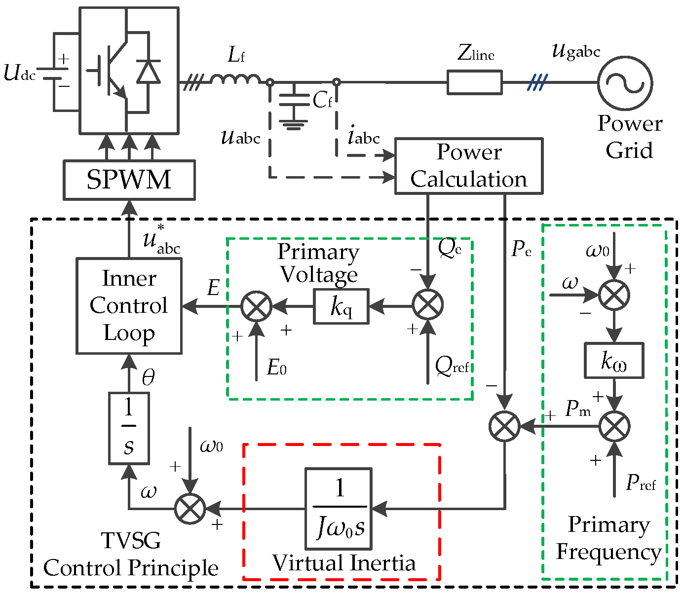
2.1. Control Principle of the TVSG

Figure 1 depicts the basic circuit topology and control strategy block diagram of a grid-connected TVSG system [24].
Therein, Udc is the DC bus voltage, Lf and Cf are the AC filter inductor and AC filter capacitor, Zline is the line equivalent connection impedance between the TVSG and power grid, u abc * and uabc are the output three-phase voltage command and output three-phase voltage of the TVSG, iabc is the grid-connected three-phase current of the TVSG, ugabc is the grid three-phase voltage. The TVSG control principle mainly consists of power calculation, primary frequency modulation, primary voltage regulation, a virtual inertia control link, and in inner control loop. The inner control loop can adopt the commonly used cascaded voltage and current controller to acquire better control performance and flexibility [25].
By mimicking the rotor motion equation of the SG, the swing equation of the TVSG can be described as follows [26]:
P ref P e = J ω 0 d ω d t + K ω ( ω ω 0 ) ,
where Pref and Pe are the active power command and output electromagnetic power of the TVSG, respectively; Pe is approximate to the GCAP if the line loss of Zline is not considered; J is the virtual inertia; ω0 and ω are the rated angular frequency and output angular frequency, respectively; and kω is the primary frequency modulation coefficient.
By simulating the excitation regulator of the SG, the reactive power-voltage regulation equation of the TVSG can be described as follows:
E = E 0 + k q Q ref Q e ,
where kq is the primary voltage modulation coefficient; E0 and E are the rated voltage amplitude and output voltage amplitude, respectively; Qref and Q are the reactive power command and grid-connected reactive power (GCRP), respectively. Therefore, the TVSG control strategy accomplishes the control of the GCAP and GCRP by adjusting the phase and amplitude of the output voltage, respectively. It is worth pointing out that the GCAP and GCRP of the TVSG can be decoupled under the condition that the Zline is inductive [25], and this paper mainly focuses on the dynamic response optimizations of the GCAP and the output frequency for the TVSG under a weak grid, as such, the GCRP-voltage regulation and inner control loop of the TVSG will not be discussed further.

2.2. Small Signal Model of TVSG

In order to analyze the dynamic response characteristics of the GCAP and the output frequency for the TVSG, it is necessary to build a small signal model of the TVSG. Figure 2 depicts the simplified power transmission model of a grid-connected TVSG system [27]. To simplify the system model, the total equivalent line resistance R contained in Zline is ignored, and X is used to represent the total equivalent line inductance of Zline. Based on the power transfer theory, the Pe of TVSG can then be established as:
P e = 3 U g E 2 X δ = 3 U g E ( ω ω g ) 2 X s ,
where Ug and ωg are the voltage amplitude and angular frequency of the power grid, respectively. Thus, the small signal model of a grid-connected TVSG system can be obtained by combining Equations (1) and (3), as described in detail in Figure 3.
According to the small signal model of a grid-connected TVSG system shown in Figure 3, the GCAP closed loop transfer function of the TVSG can be obtained as follows:
G P _ T ( s ) = Δ P e Δ P ref Δ ω g = 0 = 1.5 U g E J ω 0 X s 2 + k ω X s + 1.5 U g E ,
where the subscript “T” or the later “V” are applied to declare that the function or variable is definitely used for the TVSG or VNIAPTD-VSG. According to Equation (4), it can be found that GP_T(s) is a typical second-order control system, whose characteristic function can be written by
J ω 0 X s 2 + k ω X s + 1.5 U g E = 0 ,
where the natural oscillation angular frequency ωn and the damping ratio ζ of the TVSG can be given by
ω n = 1.5 U g E / ( J ω 0 X )   ζ = k ω 2 X / ( 1.5 U g E J ω 0 ) ,
Moreover, the closed-loop transfer function of the TVSG from the active power command disturbance to the output angular frequency according to Figure 3 can be obtained as follows:
G ω _ T ( s ) = Δ ω Δ P ref Δ ω g = 0 = X s J ω 0 X s 2 + k ω X s + 1.5 U g E ,
It can be seen from Equation (7) that Gω_T(s) is a typical second-order control system with a zero, and the natural oscillation angular frequency ωn of the system and the damping ratio ζ can also be given by Equation (6). According to Equation (6), the values of ζ and ωn decrease with the increase of J, which means the greater the dynamic oscillation amplitude and the longer the dynamic response time of Pe or ω under the Pref step disturbance. Meanwhile, the increasing value of X will increase ζ and decrease ωn, i.e., when the TVSG is integrated into a weak grid with a greater equivalent line inductance X, the dynamic oscillation amplitude of Pe or ω will be smaller and the longer the dynamic response time of Pe or ω will take.

2.3. Dynamic Response Characteristics of the TVSG under a Weak Grid

To verify the validity of the above theoretical analysis results, the main parameters of a 100kVA-TVSG in Table 1 are selected [28], and the value of ζ corresponding to different values of J and X can be calculated by using Equation (6), as described in detail in Figure 4.
It can be seen from Figure 4 that J and X determine the value of ζ. On the one hand, ζ varies inversely with J. When X is fixed, the increasing value of J will decrease ζ, leading to the dynamic oscillation amplitude, settling time and the overshoot of Pe or ω when the Pref of the TVSG is disturbed; On the other hand, ζ is proportional to X. When J is fixed, the increasing value of X will increase ζ, and the value of ζ is more sensitive to the change of X. Therefore, a larger X will further help to reduce the dynamic oscillation degree of Pe or ω.
Figure 5a,b show the bode diagrams of ΔPePref and ΔωPref for a grid-connected TVSG system with different values of ζ, respectively, which indicates the dynamic response characteristics of Pe and ω under the Pref disturbance.
As explained before, GP_T(s) is a typical second-order control system. Hence, as shown in Figure 5a, if the ζ is too small, e.g., ζ < 0.3, the bode diagram will exist a resonance peak before the cutting frequency, illustrating that a dynamic oscillation at the resonance frequency will occur. By increasing the value of ζ, the resonance peak will be eliminated gradually, so the overshoot of the Pref step response will be suppressed. However, the increase in the value of ζ also reduces the system control bandwidth, meaning a slower dynamic response speed. Therefore, the adjustment of the ζ for a grid-connected TVSG system must take into account both the overshoot suppression ability and dynamic response speed. In general, it is recommended to choose the value of ζ in the interval of [0.707, 1] [12].
Similarly, it can be seen from Figure 5b that the bode diagram of Gω_T(s) appears at the resonance peak near the damped natural frequency, implying that the ω dynamic response waveform in the time domain will exit overshoot or dynamic oscillation under the Pref step disturbance. With the increase of the value of ζ, the resonance peak decreases but cannot be eliminated completely, indicating that the ω overshoot in the time domain cannot be restrained thoroughly.
In addition, the strength and weakness characteristics of the grid can usually be characterized by the SCR [29] and are given by
SCR = U N 2 P N 1 Z line = U N 2 P N 1 X ,
where UN is the rated voltage of the power grid and PN is the rated active power of the TVSG. The grid with 2 < SCR < 3 (corresponding to 0.481 Ω < |Zline| = X < 0.722 Ω based on the main parameters in Table 1) is usually defined as a weak grid, while the grid with SCR < 2 (corresponding to |Zline| = X > 0.722 Ω) is defined as an extremely weak grid. Combining the main parameters in Table 1 with Equations (4) and (7), the step response curves of Pe and output angular frequency deviation ∆ω of the TVSG under different SCR conditions can be obtained, as shown in Figure 6a,b, respectively.
As can be seen from Figure 6a, when the SCR decreases, the overshoot and dynamic oscillation amplitude of Pe decreases but the dynamic response speed of Pe slows down. This implies that a small SCR is beneficial to improve the GCAP dynamic response characteristics and reduce the active power overshoot and oscillation amplitude but it decreases the GCAP dynamic response speed. As can be seen from Figure 6b, when SCR decreases, the dynamic oscillation degree of ∆ω decreases but the overshot of ∆ω increases. In general, decreasing the SCR will decrease the GCAP dynamic response speed and increase the overshot of ∆ω under the Pref step disturbance when the TVSG is operating and connected to a weak grid. Therefore, there is an urgent need to research optimization control strategies to improve the dynamic response performances of the GCAP and output angular frequency for the TVSG under a weak grid.

3. VNIAPTD-VSG Control Strategy

3.1. Virtual Negative Impedance Control Algorithm

In order to solve the problem that the Pe dynamic response speed is slow under a disturbance of Pref when the TVSG is integrated into a weak grid, the virtual negative impedance control algorithm is first used to reduce the total equivalent line inductance X of the grid-connected TVSG system so as to increase the Pe dynamic response speed.
Figure 7 gives the control structure diagram of the virtual impedance control algorithm [30]. Therein, Rv is the virtual resistance; Xv is the virtual inductance; eabc is the three-phase voltage command of the TVSG; e abc * is the TVSG three-phase voltage command after introducing the virtual impedance control algorithm.
According to Figure 1 and Figure 6, the mathematical expression for ugabc can be given by:
u gabc = u abc i abc Z line = G C ( s ) ( e abc i abc Z v ) i abc Z line ,
where Zv = Rv + jXv is the virtual impedance, GC(s) is the equivalent gain of the inner control loop, and GC(s) = 1 under a steady-state condition. Equation (9) can be equivalent to
u gabc = e abc i abc [ R v + s ( X + X v ) ] ,
It is worth pointing out that the iabc differential operation link included in Equation (10) will introduce high-frequency harmonic signals, which lowers the operating stability of the grid-connected TVSG system. As such, in this paper, the fundamental virtual impedance is directly simulated using Equation (11) in the dq coordinate system, so as to avoid the differential operation of iabc.
E d * E q * = E d E q R v i d i q + ω 0 L v i q i d ,
where Lv is the virtual negative inductor. The equivalent implementation of the virtual fundamental impedance algorithm in the dq coordinate system can be obtained from Equation (11), as shown in Figure 8 [31].
Figure 8a shows the integral control structure, whereas Figure 8b shows the inner control loop. Therein, Ed = E is the d axis output voltage amplitude, Eq = 0 is the q axis output voltage amplitude, E d * is the d axis output voltage amplitude command, E q * is the q axis output voltage amplitude command. In the inductive line (|Zline| = X) conditions, introducing only the virtual negative inductance can reduce the equivalent line inductance of the grid-connected TVSG system, hence set Rv = 0. From Equation (11), if the TVSG is connected to an extremely weak grid with SCR = 1 (X = 1.44 Ω), the corresponding ωn = 5.66 rad/s, ζ = 0.45, which can directly reduce its line equivalent inductance Xeq from 1.44 Ω to 0.48 Ω (Xeq = X + ω0Lv = 0.48 Ω) by selecting Lv = −3.1 mH, which is equivalent to increasing the SCR from 1 to 3, and the corresponding ω n = 9.8 rad / s > ω n , ζ = 0.26 < ζ .
Based on the above theoretical analysis, it can be found from Figure 6 that the virtual negative impedance algorithm can reduce the equivalent line reactance X of the grid-connected TVSG system and increase the Pe dynamic response speed ( ω n > ω n ) but intensify the dynamic oscillation degrees of Pe and ω ( ζ < ζ ).

3.2. Active Power Transient Damping (APTD) Control Algorithm

To solve the intensification of the dynamic oscillation amplitude of Pe and the dynamic oscillation degree of ω for the TVSG with the virtual negative impedance control algorithm, the APTD control algorithm is proposed to enhance the transient damping of the grid-connected TVSG system and restrain the dynamic oscillations of Pe and ω. The small signal model of the grid-connected VNIAPTD-VSG system is shown in Figure 9a, where A and B are the dynamic compensation coefficient and proportional compensation coefficient of APTD, respectively.
According to the small signal model of the grid-connected VNIAPTD-VSG system shown in Figure 9a, the GCAP closed loop transfer function of VNIAPTD-VSG can be obtained as follows:
G P _ V ( s ) = Δ P e Δ P ref Δ ω g = 0 = 1.5 U g E A s + 1.5 U g E ( 1 + B ) J ω 0 X eq s 2 + ( X eq k ω + 1.5 U g E A ) s + 1.5 U g E ( 1 + B ) ,
By comparing Equations (4) and (12), it is not difficult to find that GP_V(s) has an additional differential term in the numerator compared with GP_T(s), which introduces a zero to the grid-connected VNIAPTD-VSG system. The differential term can help to improve the Pe dynamic response speed and predict the occurrence of the dynamic oscillation and overshoot of Pe in advance and produce an appropriate reaction in time to stop the tendencies to large dynamic oscillation and overshoot. It is worth pointing out that although it benefits from the differential term in GP_V(s), the actual APTD algorithm does not need to carry out differential operation by introducing the equivalent small signal model of the grid-connected VNIAPTD-VSG system as shown in Figure 9b, and as such, the instability risk that may be brought by the differential term is avoided.
According to Equation (12), it can be found that GP_V(s) is also a second-order control system, whose characteristic function can be written by
J ω 0 X eq s 2 + ( X eq k ω + 1.5 U g E A ) s + 1.5 U g E ( 1 + B ) = 0 ,
where the natural oscillation angular frequency ωn1 and the damping ratio ζ1 of VNIAPTD-VSG can be given by
ω n 1 = 1.5 U g E ( 1 + B ) / J ω 0 X eq , ζ 1 = 1.5 U g E A + X eq k ω 2 1.5 U g E ( 1 + B ) J ω 0 X eq ,
By comparing Equations (6) and (14), it can be seen that the VNIAPTD-VSG can select a larger natural oscillation angular frequency by increasing the value of B and obtain a larger damping ratio by increasing the value of A compared to the TVSG. Therefore, once J, X, and kω are set, the natural oscillation angular frequency of the TVSG will be fixed, while the role of A in the VNIAPTD-VSG is the same as that of kω in the TVSG damping control. Hence, A can be used as the additional damping coefficient of the VNIAPTD-VSG, which means that adjusting A can make a desirable regulation of the damping ratio ζ1 for VNIAPTD-VSG.
Moreover, the closed-loop transfer function of the VNIAPTD-VSG from the active power command disturbance to the output angular frequency according to Figure 9a can be obtained as follows:
G ω _ V ( s ) = Δ ω Δ P ref Δ ω g = 0 = X eq s J ω 0 X eq s 2 + ( X eq k ω + 1.5 U g E A ) s + 1.5 U g E ( 1 + B ) ,
It can be seen from Equation (15) that Gω_V(s) is also a second-order control system with a zero, and the natural oscillation angular frequency ωn1 and the damping ratio ζ1 of the system can also be given by Equation (14). According to Equation (14), ωn1 increases with the increasing B, i.e., the larger the value of B, the more rapid the dynamic response speed of the system. Therefore, a larger B must be chosen to increase the dynamic response speed of Pe when the VNIAPTD-VSG is connected to a weak grid. Conversely, ζ1 decreases as B increases, i.e., the larger the value of B, the lower the damping capacity of the Pe dynamic oscillation will be. Furthermore, increasing the value of A has no effect on the value of ωn1 and the dynamic response speed of the grid-connected VNIAPTD-VSG system but it can effectively compensate for the reduction of ζ1 caused by the increase of B. Therefore, the Pe dynamic response speed of the grid-connected VNIAPTD-VSG system is improved by adjusting the value of B first, and the ability of the system to suppress the Pe dynamic oscillation is then enhanced by tuning the value of A in this paper.
Given that, when A = 0, the root locus of the grid-connected VNIAPTD-VSG system during the increase of B from 0 to 25 (step of 0.5) can be obtained by using Equation (13), as shown in detail in Figure 10a. According to Figure 10a, it is not difficult to find that the value of ωn1 increases significantly with the increase of B in the interval of B ∈ [0, 10] but the value of ωn1 increases slowly with the increase of B in the interval of B ∈ (10, 25), indicating that the ability to improve the Pe dynamic response speed is weak. At the same time, the value of ζ1 continues to decrease with the increase of B in the interval of B ∈ (10, 25), which will have an adverse effect on the suppression ability of the Pe dynamic oscillation. In order to weigh the dynamic response speed and its dynamic oscillation suppression ability of Pe, set B = 10 in this paper, and then ωn1 = 32.5 rad/s, which is roughly equal to 3.3 times ω n .
Likewise, when B = 10, the root locus of the grid-connected VNIAPTD-VSG system during the increase of A from 0 to 3 (step of 0.05) can be obtained by using Equation (13), as described in detail in Figure 10b.
According to Figure 10b, it is easy to find that as A is gradually increased, a pair of conjugate poles of the system gradually move away from the imaginary axis and approach the real axis, and both of them fall on the negative real axis when A ≥ 0.7, i.e., the system transitions from the underdamped state to the overdamped one; the dominant poles of the system approach the origin rapidly as A is increased when A ∈ [0.7, 2], and the damping of the system increases rapidly; whereas A ∈ (2, 3) as A continues to increase, the damping of the system does not increase significantly, and one of the poles will gradually move closer to the origin which will threaten the operational stability of the grid-connected VNIAPTD-VSG system; thus, A = 2 is fixed in this paper, corresponding to ζ1 = 3.03, which is roughly equal to 11.7 times ζ to compensate effectively for the decrease in the damping ratio ζ1 as a result of the increase in B.
Similarly, Figure 11a,b show the bode diagrams of ΔPePref for the grid-connected VNIAPTD-VSG system with different values of ωn1 and ζ1, respectively, which indicates the dynamic response characteristics of Pe following a Pref disturbance. As explained before, GP_V(s) is also a second-order control system and can select a larger ωn1 just by increasing the value of B compared with GP_T(s). Hence, it can be seen from Figure 11a that the increase of the value of ωn1 improves the control bandwidth of the gird-connected VNIAPTD-VSG system, indicating a faster Pe dynamic response speed. However, the increase of the value of ωn1 also increases the resonance peak, illustrating that a Pe dynamic oscillation at the resonance frequency will occur. Thus, VNIAPTD-VSG needs to increase the value of A to increase the value of ζ1, so as to improve the suppression ability of the Pe dynamic oscillation.
As explained before, increasing the value of A has no effect on the value of ωn1 and can enhance the ability of the grid-connected VNIAPTD-VSG system to suppress the Pe dynamic oscillation. Hence, it can be seen from Figure 11b that the resonance peak in the bode diagrams will be eliminated gradually by increasing the value of ζ1 (B = 10, ωn1 = 33 rad/s), so the overshoot of the Pref step response will be suppressed. As opposed to the TVSG, increasing the value of ζ1 will have no effect on the bandwidth of the VNIAPTD-VSG, that is, it will not reduce the Pe dynamic response speed.
In conclusion, enlarging the values of ωn1 and ζ1 of the grid-connected VNIAPTD-VSG system can make both the dynamic response speed and the overshoot suppression ability of Pe approximate to the desirable response performances simultaneously. Therefore, for the VNIAPTD-VSG, larger values of ωn1 and ζ1, viz., and larger values of B and A are required. The VNIAPTD-VSG can solve the inherent contradiction between the overshoot suppression ability and dynamic response speed of Pe, thus, the VNIAPTD-VSG can obtain better Pe overshoot suppression ability and faster Pe dynamic response speed compared to the TVSG.
Figure 12a,b show the bode diagrams of ΔωPref for the grid-connected VNIAPTD-VSG system with different values of ωn1 and ζ1, respectively, which indicates the dynamic response characteristics of ω under a Pref step disturbance.
It can be seen from Figure 12a that the increase in the value of ωn1 improves the control bandwidth of the grid-connected VNIAPTD-VSG system, indicating a faster ω dynamic response speed. However, the increase of the value of ωn1 does not affect the resonance peak, which indicates that a ω dynamic oscillation at the resonance frequency will still occur. Therefore, the VNIAPTD-VSG needs to increase the value of A to increase the value of ζ1, so as to improve the suppression ability of the ω dynamic oscillation. As explained before, increasing the value of A has no effect on the value of ωn1 and can enhance the ability of the grid-connected VNIAPTD-VSG system to suppress the ω dynamic oscillation. Hence, it can be seen from Figure 12b that the resonance peak in the bode diagrams will be eliminated gradually by increasing the value of ζ1 (B = 10, ωn1 = 33 rad/s), which illustrates that the ω overshoot under the Pref disturbance will be suppressed effectively.
In conclusion, enlarging the values of ωn1 and ζ1 of the grid-connected VNIAPTD-VSG system can make both the dynamic response speed and overshoot suppression ability of ω get close to the desirable response performances simultaneously. Thus, for the VNIAPTD-VSG, larger values of ωn1 and ζ1, i.e., larger values of B and A, are required. VNIAPTD-VSG can solve the inherent contradiction between the dynamic response speed and overshoot suppression ability of ω, thus, the VNIAPTD-VSG can obtain a better ω dynamic oscillation suppression ability and shorter ω regulation time compared to the TVSG.
In summary, the proposed VNIAPTD-VSG can solve the inherent contradiction between the control objectives of Pe and ω under the Pref step disturbance when the TVSG is connected to a weak grid according to the above theoretical analyses, indicating that the VNIAPTD-VSG can obtain desirable dynamic response performances of Pe and ω simultaneously, i.e., fast Pe dynamic response speed without overshoot or oscillation and yet with a small ω overshoot amplitude.

4. Simulation and Experimental Verifications

4.1. Simulation Results and Analysis

In order to verify the feasibility of the proposed VNIAPTD-VSG control strategy in optimizing the dynamic response performances of the GCAP and output angular frequency for the TVSG under a weak grid, a grid-connected 100kVA-TVSG simulation model in Figure 1 is established by using Matlab2016a/Simulink simulation software. In the simulations, A = 2 and B = 10 are selected, and X = 1.44 Ω (corresponding to SCR = 1) is set directly to simulate an operation scenario where the 100kVA-TVSG is incorporated into an extremely weak grid, and the other control parameters and main circuit parameters are shown in Table 1. The simulation conditions are set as follows: at the initial moment, 100kVA-TVSG is connected to an extremely weak grid with SCR = 1 and the GCAP is 20 kW, while its Pref jumps from 20 kW to 60 kW at 4 s.
The purpose of this subsection is to validate the difference in the dynamic response performances of the Pe and output frequency f between the TVSG and VNIAPTD-VSG in the weak grid scenario, as well as the effect of the virtual negative impedance and the VNIAPTD control algorithm on the dynamic responses of Pe and f through simulation. The comparative simulation results of Pe and f are given in Figure 13 when different control strategies are applied to the 100kVA-TVSG.
Figure 13a shows the Pe dynamic response curves, whereas Figure 13b shows the f dynamic response curves. From Figure 13a, it can be seen that the overshoot and dynamic oscillation amplitude of Pe are small but that the dynamic response time is long because the TVSG (Lv = 0) without the virtual negative impedance algorithm has a large ζ = 0.45 but a small ωn = 5.66 rad/s when it is incorporated into an extremely weak grid with SCR = 1. When the virtual negative impedance algorithm (Lv = −3.1 mH) is applied to the TVSG, the equivalent SCR of the grid increases from 1 to 3, correspondingly ωn increases from 5.66 rad/s to 9.8 rad/s but ζ decreases from 0.45 to 0.26, magnifying the dynamic response speed, overshot, and dynamic oscillation amplitude of Pe. When the proposed VNIAPTD control algorithm is applied to the VNIAPTD-VSG, the ζ1 of the VNIAPTD-VSG is 3.03 times larger than 0.45, and the ωn1 of the VNIAPTD-VSG is equal to 32.5 rad/s higher than 9.8 rad/s, which in turn can eliminate the overshot and dynamic oscillation of Pe while increasing the dynamic response speed of Pe.
From Figure 13b, it can be seen that the f dynamic response has an obvious overshoot phenomenon with an overshoot amplitude of 0.21 Hz when TVSG (Lv = 0) is integrated into an extremely weak grid with SCR = 1. The overshoot amplitude of f can be reduced from 0.21 Hz to 0.15 Hz by the virtual negative impedance algorithm (Lv = −3.1 mH) but the dynamic oscillation of f increases, which may threaten the stable operation of the grid-connected TVSG system. Compared to the TVSG, the VNIAPTD-VSG has a smaller f overshoot amplitude and no dynamic oscillation in the dynamic response process without affecting the rate of change of frequency (RoCoF). As such, the dynamic response performances of Pe and f for the VNIAPTD-VSG under the Pref step disturbance are superior to that of the TVSG under a weak grid.

4.2. Experimental Results and Analysis

To further validate the effectiveness of the VNIAPTD-VSG control algorithm proposed in the paper, three-phase 100kVA-VSG prototypes were tested in a microgrid experiment platform [32], with the main control parameters and detailed circuit parameters shown in Table 1. In the experiments, each 100kVA-VSG was controlled by an independent DSP TMS320F28335, which implemented the proposed control algorithms, as presented in the previous sections. Figure 14a,b show the structure diagram and photographs of the complete microgrid experiment platform, respectively. Figure 14c shows a 100kVA-VSG in the test process.
In the experiments, Lv = −2.1 mH was selected and the other parameters were selected in the same way as the simulation parameters in Section 4.1. The experimental conditions were set as follows: at the initial moment, 100kVA-TVSG was connected to an extremely weak grid with SCR = 1 and the GCAP was 20 kW, while its Pref jumped from 20 kW to 60 kW at 4.5 s. The comparative experimental results of Pe and f are given in Figure 15 when different control strategies were applied to the 100kVA-TVSG. Figure 15a shows the Pe dynamic response curves, whereas Figure 15b shows the f dynamic response curves.
From Figure 15a, it can be seen that when the 100kVA-TVSG is incorporated into an extremely weak grid with SCR = 1, the virtual negative impedance algorithm (Lv = −2.1 mH) can effectively improve the dynamic response speed of Pe but it increases the overshot and dynamic oscillation amplitude of Pe. Compared to the TVSG, the VNIAPTD-VSG first uses the virtual negative impedance algorithm to enhance the dynamic response speed of Pe and then uses the active power transient damping algorithm to improve the dynamic oscillation suppression capability of Pe, i.e., the former can effectively solve the problems of the slow dynamic response speed, overshot, and dynamic oscillation of Pe exiting in the latter, which can correspond to Figure 13a.
It can be seen from Figure 15b that the TVSG has a large overshoot amplitude of 0.2 Hz in its f dynamic response when it is integrated into an extremely weak grid with SCR = 1. The overshoot amplitude of f can be reduced from 0.2 Hz to 0.17 Hz by the virtual negative impedance algorithm (Lv = −2.1 mH), but the dynamic oscillation of f increases. Compared to the TVSG, the VNIAPTD-VSG has no f dynamic oscillation and a smaller f overshoot amplitude of 0.06 Hz without affecting the RoCoF, which means that the VNIAPTD-VSG has a better dynamic response performance at its f, which can correspond to Figure 13b. This implies that the dynamic response performances of Pe and f for the VNIAPTD-VSG under the Pref step disturbance are superior to that of the TVSG under a weak grid. Moreover, the f overshoot amplitude of the VNIAPTD-VSG with Lv = −3.1mH (corresponding to SCR = 3) in Figure 13b is smaller than that of the VNIAPTD-VSG with Lv = −2.1mH (corresponding to SCR = 1.85) in Figure 15b according to the theoretical analysis results in Figure 6b.
The above simulation and experimental results demonstrate the conclusions obtained from the previous theoretical analysis and verify the superior dynamic response performances of the VNIAPTD-VSG compared with the TVSG. The main reason for these advantages is that the proposed VNIAPTD-VSG fundamentally solves the three inherent contradictions among the different control objectives of the TVSG. Finally, these advantages of the VNIAPTD-VSG under the weak grid conditions and the corresponding main reasons are shown in Table 2.

5. Conclusions

In order to solve the inherent contradiction between the control objectives of Pe and f under the Pref step disturbance when the TVSG is connected to a weak grid, an optimization strategy of the GCAP dynamic response for the TVSG based on the VNIAPTD control algorithm is proposed in this paper. Through the theoretical analysis, mathematical modeling, and parameter design, as well as through simulation and experiment verifications, the following conclusions are drawn:
(1)
When the TVSG is connected to a weak grid, the dynamic oscillation amplitude of Pe decreases with SCR but its Pe dynamic response speed slows down, yet its f overshoot amplitude increases under the Pref step disturbance.
(2)
Although the control strategy based on the virtual negative impedance algorithm can reduce the equivalent line inductance of the grid-connected TVSG system and the Pe dynamic response time, it can increase the Pe dynamic oscillation amplitude and the f dynamic oscillation degree under a disturbance of Pref when the TVSG is operating and connected to a weak grid.
(3)
The proposed VNIAPTD-VSG can solve the inherent contradiction between the overshoot suppression ability and dynamic response speed of Pe, thereby obtaining a better Pe overshoot suppression ability and faster Pe dynamic response speed compared with the TVSG. The VNIAPTD-VSG can solve the inherent contradiction among the overshoot suppression ability, RoCoF, and dynamic response speed of f, thereby obtaining a better f dynamic oscillation suppression ability and shorter f regulation time without affecting the RoCoF compared to the TVSG. The VNIAPTD-VSG can solve the inherent contradiction between the control objectives of Pe and f, thereby achieving desirable dynamic response performances of Pe and f simultaneously.

Author Contributions

Conceptualization, R.S. and C.L.; methodology, R.S.; validation, R.S. and C.L.; formal analysis, R.S.; investigation, R.S. and C.L.; writing—original draft preparation, C.L.; writing—review and editing, R.S. and J.H.; supervision, J.H. and C.J.; project administration, R.S. and C.J. All authors have read and agreed to the published version of the manuscript.

Funding

This research was funded by the Guangxi Natural Science Foundation of China under grant numbers 2020GXNSFBA297124 and 2021GXNSFAA220038, and the Guangxi Key Research and Development Project of China under grant number 2021AB03043.

Data Availability Statement

Contained within the text and cited references.

Acknowledgments

This work was supported by the Automation Department of the College of Mechanical and Control Engineering at Guilin University of Technology.

Conflicts of Interest

The authors declare no conflict of interest.

Nomenclature

The following abbreviations are used in this manuscript:
Pref, QrefCommand of active power and reactive power
Pe, QeGrid-connected active power and grid-connected reactive power
JVirtual inertia
ω0, ωRated angular frequency and output angular frequency
fOutput frequency
XCircuit equivalent reactance
kωPrimary frequency modulation coefficient
kqPrimary voltage modulation coefficient
E0, ERated voltage amplitude and output voltage amplitude
Ug, ωgGrid voltage amplitude and gird angular frequency
ωn, ωn1Natural oscillation angular frequency
ζ, ζ1Damping ratio
Rv, XvVirtual resistance and virtual inductance
LvVirtual negative inductor
ADynamic compensation coefficient of APTD
BProportional compensation coefficient of APTD
RESsRenewable energy sources
SGSynchronous generator
VSGVirtual synchronous generator
GCAPGrid-connected active power
GCRPGrid-connected reactive power
APTDActive power transient damping
VNIAPTDVirtual negative impedance combined with the active power transient damping
TVSGTypical VSG
VNIAPTD-VSGVSG with VNIAPTD control algorithm
SCRShort circuit ratio

References

  1. Liu, Y.Q.; Chen, L.X.; Han, X.Q. The key problem analysis on the alternative new energy under the energy transition. Proc. CSEE 2022, 42, 515–523. [Google Scholar]
  2. Zhong, Q.C. Power-electronics-enabled autonomous power systems: Architecture and technical routes. IEEE Trans. Ind. Electron. 2017, 64, 5907–5918. [Google Scholar] [CrossRef]
  3. Yuan, X.M.; Zhang, M.Q.; Chi, Y.N.; Ju, P. Basic challenges of and technical roadmap to power-electronized power system dynamics issues. Proc. CSEE 2022, 42, 1904–1916. [Google Scholar]
  4. Wang, X.F.; Taul, M.G.; Wu, H.; Liao, Y.C.; Blaabjerg, F.; Harnefors, L. Grid-synchronization stability of converter- based resources—An overview. IEEE Open J. Ind. Appl. 2020, 1, 115–134. [Google Scholar] [CrossRef]
  5. Wang, X.F.; Blaabjerg, F. Harmonic stability in power electronic-based power systems: Concept, modeling, and analysis. IEEE Trans. Smart Grid 2019, 10, 2858–2870. [Google Scholar] [CrossRef] [Green Version]
  6. Laaksonen, H. Improvement of power system frequency stability with universal grid-forming battery energy storages. IEEE Access 2023, 11, 10826–10841. [Google Scholar] [CrossRef]
  7. Chen, S.M.; Sun, Y.; Han, H.; Fu, S.Q.; Luo, S.H.; Shi, G.Z. A modified VSG control scheme with virtual resistance to enhance both small-signal stability and transient synchronization stability. IEEE Trans. Power Electron. 2023, 38, 6005–6014. [Google Scholar] [CrossRef]
  8. Lu, S.; Zhu, Y.; Dong, L.; Na, G.; Hao, Y.; Zhang, G.; Zhang, W.; Cheng, S.; Yang, J.; Sui, Y. Small-signal stability research of grid-connected virtual synchronous generators. Energies 2022, 15, 7158. [Google Scholar] [CrossRef]
  9. Sang, W.; Guo, W.; Dai, S.; Tian, C.; Yu, S.; Teng, Y. Virtual synchronous generator, a comprehensive overview. Energies 2022, 15, 6148. [Google Scholar] [CrossRef]
  10. Sun, P.; Yao, J.; Zhao, Y.; Fang, X.; Cao, J.Y. Stability assessment and damping optimization control of multiple grid connected virtual synchronous generators. IEEE Trans. Energy Convers. 2021, 36, 3555–3567. [Google Scholar] [CrossRef]
  11. Wu, G.T.; He, Y.Y.; Zhang, H.; Wang, X.H.; Pan, D.H.; Ruan, X.B.; Yao, C. Passivity-based stability analysis and generic controller design for grid-forming inverter. IEEE Trans. Power Electron. 2023, 38, 5832–5843. [Google Scholar] [CrossRef]
  12. Li, M.X.; Yu, P.; Hu, W.H.; Wang, Y.; Shu, S.R.; Zhang, Z.Y.; Blaabjerg, F. Phase feedforward damping control method for virtual synchronous generators. IEEE Trans. Power Electron. 2022, 37, 9790–9806. [Google Scholar] [CrossRef]
  13. Fang, J.Y.; Lin, P.F.; Li, H.C.; Yang, Y.H.; Tang, Y. An improved virtual inertia control for three-phase voltage source converters connected to a weak grid. IEEE Trans. Power Electron. 2019, 34, 8660–8670. [Google Scholar] [CrossRef] [Green Version]
  14. Rathnayake, D.B.; Me, S.P.; Razzaghi, R.; Bahrani, B. H∞-based control design for grid-forming inverters with enhanced damping and virtual inertia. IEEE J. Emerg. Sel. Top. Power Electron. 2023, 11, 2311–2325. [Google Scholar] [CrossRef]
  15. Liu, H.; Yang, B.; Xu, S.; Du, M.J.; Lu, S. Universal virtual synchronous generator based on extended virtual inertia to enhance power and frequency response. Energies 2023, 16, 2983. [Google Scholar] [CrossRef]
  16. Xu, H.Z.; Yu, C.Z.; Liu, C.; Wang, Q.L.; Zhang, X. An improved virtual inertia algorithm of virtual synchronous generator. J. Mod. Power Syst. Clean Energy 2020, 8, 377–386. [Google Scholar] [CrossRef]
  17. Li, M.X.; Wang, Y.; Xu, N.Y.; Niu, R.G.; Lei, W.J. Control strategy of virtual synchronous generator based on band-pass damped power feedback. Trans. China Electrotech. Soc. 2018, 33, 2176–2185. [Google Scholar]
  18. Shuai, Z.K.; Huang, W.; Shen, Z.J.; Luo, A.; Tian, Z. Active power oscillation and suppression techniques between two parallel synchronverters during load fluctuations. IEEE Trans. Power Electron. 2020, 35, 4127–4142. [Google Scholar] [CrossRef]
  19. Jiang, J.Y.; Wang, W.; Tang, F.; Wu, X.Z.; Yang, Z.W. d-axis current differential feedforward control for improving the dynamic characteristic of energy storage virtual synchronous generator. Power Syst. Tech. 2022, 46, 2510–2523. [Google Scholar]
  20. Zhang, Y.N.; Zhou, X.M. Virtual synchronous generator control technology with fractional virtual inertia for grid-connected inverters. Control Dec. 2021, 36, 463–468. [Google Scholar]
  21. Lan, Z.; Long, Y.; Zeng, J.H.; Tu, C.M.; Xiao, F. Transient power oscillation suppression strategy of virtual synchronous generator considering overshoot. Auto. Elect. Power Syst. 2022, 46, 131–141. [Google Scholar]
  22. Lan, Z.; Long, Y.; Zeng, J.H.; Lv, Z.P.; He, D. VSG control strategy introducing transient electromagnetic power compensation. Power Syst. Tech. 2022, 46, 1421–1429. [Google Scholar]
  23. Yu, Y.; Chaudhary, S.K.; Tinajero, G.D.; Xu, L.N.; Bakar, N.; Vasquez, J.C.; Guerrero, J.M. A reference-feedforward-based damping method for virtual synchronous generator control. IEEE Trans. Power Electron. 2022, 37, 7566–7571. [Google Scholar] [CrossRef]
  24. Li, M.; Zhang, X.; Guo, Z.X.; Wang, J.L.; Wang, Y.; Li, F.; Zhao, W. The control strategy for the grid-connected inverter through impedance reshaping in q-axis and its stability analysis under a weak grid. IEEE J. Emerg. Sel. Top. Power Electron. 2021, 9, 3229–3242. [Google Scholar] [CrossRef]
  25. Arco, S.D.; Suul, J.A.; Fosso, O.B. A virtual synchronous machine implementation for distributed control of power converters in SmartGrids. Elect. Power Syst. Res. 2015, 122, 180–197. [Google Scholar]
  26. Liu, J.; Miura, Y.; Ise, T. Comparison of dynamic characteristics between virtual synchronous generator and droop control in inverter-based distributed denerators. IEEE Trans. Power Electron. 2016, 31, 3600–3611. [Google Scholar] [CrossRef]
  27. Liu, J.; Miura, Y.; Bevrani, H.; Ise, T. A unified modeling method of virtual synchronous generator for multi-operation-mode analyses. IEEE J. Emerg. Sel. Topics Power Electron. 2021, 9, 2394–2409. [Google Scholar] [CrossRef]
  28. Shi, R.L.; Zhang, X.; Hu, C.; Xu, H.Z.; Gu, J.; Cao, W. Self-tuning virtual synchronous generator control for improving frequency stability in autonomous photovoltaic-diesel microgrids. J. Mod. Power Syst. Clean Energy 2018, 6, 482–494. [Google Scholar] [CrossRef] [Green Version]
  29. Li, M.; Zhang, X.; Guo, Z.X.; Pan, H.L.; Ma, M.Y.; Zhao, W. Impedance adaptive dual-mode control of grid-connected inverters with large fluctuation of SCR and its stability analysis based on D-partition method. IEEE Trans. Power Electron. 2021, 36, 14420–14435. [Google Scholar] [CrossRef]
  30. Huang, L.B.; Xin, H.H.; Yuan, H.; Wang, G.Z.; Ju, P. Damping effect of virtual synchronous machines provided by a dynamical virtual impedance. IEEE Trans. Energy Conver. 2021, 36, 570–573. [Google Scholar] [CrossRef]
  31. Ren, M.W.; Li, T.; Shi, K.; Xu, P.F.; Sun, Y.X. Coordinated control strategy of virtual synchronous generator based on adaptive moment of inertia and virtual impedance. IEEE J. Emerg. Sel. Topics Cir. Syst. 2021, 11, 99–110. [Google Scholar] [CrossRef]
  32. Shi, R.L.; Zhang, X. VSG-based dynamic frequency support control for autonomous PV-diesel microgrids. Energies 2018, 11, 1814–1829. [Google Scholar] [CrossRef] [Green Version]
Figure 1. Block diagram of a grid-connected TVSG system.
Energies 16 04593 g001
Figure 2. Simplified power transmission model of a grid-connected TVSG system.
Energies 16 04593 g002
Figure 3. Small signal model of a grid-connected TVSG system.
Energies 16 04593 g003
Figure 4. The ζ values corresponding to different J and X.
Energies 16 04593 g004
Figure 5. Bode diagrams of a grid-connected TVSG system with different values of ζ: (a) GCAP responses under the Pref disturbance (ΔPePref); (b) output frequency responses under the Pref disturbance (ΔωPref).
Energies 16 04593 g005
Figure 6. Step response curves under different SCR conditions: (a) Pe, (b) ∆ω.
Energies 16 04593 g006
Figure 7. Control block diagram of the virtual impedance control algorithm.
Energies 16 04593 g007
Figure 8. Virtual fundamental impedance algorithm in dq coordinate system: (a) integral control structure; (b) inner control loop.
Energies 16 04593 g008
Figure 9. Small signal model of the grid-connected VNIAPTD-VSG system: (a) original model; (b) equivalent model.
Energies 16 04593 g009aEnergies 16 04593 g009b
Figure 10. Root locus of the grid-connected VNIAPTD-VSG system: (a) A = 0, B ∈ [0, 25]; (b) B = 10, A ∈ [0, 3].
Energies 16 04593 g010
Figure 11. Bode diagrams of GCAP responses under the Pref disturbance (ΔPePref) for the grid-connected VNIAPTD-VSG system: (a) change the value of ωn1; (b) change the value of ζ1.
Energies 16 04593 g011
Figure 12. Bode diagrams of output angular frequency responses under the Pref disturbance (ΔωPref) for the grid-connected VNIAPTD-VSG system: (a) change the value of ωn1; (b) change the value of ζ1.
Energies 16 04593 g012
Figure 13. Comparative simulation results of the TVSG and VNIAPTD-VSG when the Pref steps from 20 kW to 60 kW at 4 s: (a) Pe dynamic response curves, (b) f dynamic response curves.
Energies 16 04593 g013
Figure 14. Microgrid experiment platform: (a) structure diagram, (b) photograph, (c) a 100kVA-VSG prototype.
Energies 16 04593 g014
Figure 15. Comparative experimental results of the TVSG and VNIAPTD-VSG when the Pref steps from 20 kW to 60 kW at 4.5 s: (a) Pe dynamic response curves, (b) f dynamic response curves.
Energies 16 04593 g015
Table 1. The main parameters of a 100kVA-TVSG.
SymbolParameterValue
E0Rated voltage amplitude311 V
UdcDC bus voltage700 V
ω0Rated angular frequency314.15 rad/s
JVirtual inertia10 kg·m2
kqPrimary voltage regulation coefficient1.4 × 10−4 V/var
kωPrimary frequency modulation coefficient15,915.5 J/rad
LfFilter inductance50.6 mH
CfFilter capacitor270 uF
fsSampling frequency5 kHz
Table 2. Advantages of the proposed VNIAPTD-VSG compared with the TVSG.
NumbersAdvantagesReasons
1VNIAPTD-VSG can obtain better Pe overshoot suppression ability and faster Pe dynamic response speed compared with TVSG.VNIAPTD-VSG can solve the inherent contradiction between the overshoot suppression ability and dynamic response speed of Pe.
2VNIAPTD-VSG can obtain better f dynamic oscillation suppression ability and shorter f regulation time without affecting RoCoF compared with TVSG.VNIAPTD-VSG can solve the inherent contradiction among the overshoot suppression ability, RoCoF and dynamic response speed of f.
3VNIAPTD-VSG can obtain desirable dynamic response performances of Pe and f simultaneously, i.e., fast Pe dynamic response speed without overshoot or oscillation yet small f overshoot amplitude without affecting RoCoF.VNIAPTD-VSG can solve the inherent contradiction between the control objectives of Pe and f under the Pref step disturbance when TVSG is connected to a weak grid.
Disclaimer/Publisher’s Note: The statements, opinions and data contained in all publications are solely those of the individual author(s) and contributor(s) and not of MDPI and/or the editor(s). MDPI and/or the editor(s) disclaim responsibility for any injury to people or property resulting from any ideas, methods, instructions or products referred to in the content.

