Article

Optimizing Energy Harvesting: A Gain-Scheduled Braking System for Electric Vehicles with Enhanced State of Charge and Efficiency

by
Anith Khairunnisa Ghazali
1,
Mohd Khair Hassan
2,*,
Mohd Amran Mohd Radzi
2 and
Azizan As’arry
3
1
Faculty of Engineering & Technology, Multimedia University, Bukit Beruang 75450, Melaka, Malaysia
2
Department of Electrical and Electronic Engineering, Faculty of Engineering, University Putra Malaysia, Serdang 43400, Selangor, Malaysia
3
Department of Mechanical and Manufacturing Engineering, Faculty of Engineering, University Putra Malaysia, Serdang 43400, Selangor, Malaysia
*
Author to whom correspondence should be addressed.
Energies 2023, 16(12), 4561; https://doi.org/10.3390/en16124561
Submission received: 18 April 2023 / Revised: 31 May 2023 / Accepted: 1 June 2023 / Published: 7 June 2023

Abstract

:
Recycling braking energy is crucial in increasing the overall energy efficiency of an electric vehicle. Regenerative braking system (RBS) technology makes a significant contribution, but it is quite challenging to design an optimal braking force distribution while ensuring vehicle stability and battery health. In this study, a parallel-distribution braking system that transfers as much energy as possible from the wheel to the battery was investigated. An integrated braking force distribution with gain-scheduling super-twisting sliding mode control (GSTSMC) was proposed to capture the maximum kinetic energy during braking and convert it into electrical energy. Parallel friction and regenerative braking ratios dominate the design of the braking component, which is based on the speed of the vehicle. A GSTSMC was implemented and incorporated into the vehicle dynamics model developed in the ADVISOR environment. Simulation was utilized to rigorously validate the efficacy of the proposed control strategy, ensuring its potential to perform optimally in practical applications. Consideration was given to the vehicle’s slip ratio on dry asphalt to maintain vehicle stability. Simulation results were used to validate the performance of the proposed design in terms of the state of charge (SOC), transmitted energy, motor efficiency, battery temperature, and slip ratio. Based on the results, the proposed control strategy is capable of increasing the SOC value to 54%, overall efficiency to 25.98%, energy transmitted to 14.27%, and energy loss to 87 kJ while considering the vehicle’s speed-tracking ability, battery temperature, and stability.

1. Introduction

Due to the shortage of resources and environmental problems, electric vehicle development has become a trend in an effort to replace conventional internal combustion engine vehicles [1]. However, the most critical problem of electric vehicles is their limitation in driving range. Therefore, regenerative braking has been introduced to overcome this problem. A regenerative braking system (RBS) is an energy recovery system that converts kinetic energy to electrical or mechanical energy. During deceleration, the vehicle slows down, and kinetic energy is released in the form of heat. Throughout the braking process, the captured kinetic and potential energy are transformed into electrical energy and stored in an energy storage system, such as a battery or a super-capacitor. Regenerative braking is an effective approach that improves vehicle performance, such as range and efficiency, especially in heavy stop-and-go traffic conditions or city driving due to frequent braking [2]. According to [3,4], one-third to one-half of energy is consumed during braking in urban driving. Another finding by [5] determined that there is about 50% or more driving energy lost during braking in urban conditions and 20% in suburban conditions. Consequently, if the wasted energy is successfully recovered, driving mileage may increase by 10% to 30%. Driving range is a vital issue for electric vehicles which depends on several factors such as driving style, weather, and desired comfort. The New European Driving Cycle (NEDC) is used to represent a start-stop drive cycle. Designing an effective braking system would be a good approach to solve this limitation. Even though the Worldwide Harmonized Light Vehicles Test Procedure (WLTP) was introduced as a more accurate testing procedure than the NEDC, but the transition to WLTP is not fully complete in some regions. As a result, many vehicles on the road were tested under the NEDC. Researching EV driving patterns using NEDC allows for standardized testing and comparison while providing insights into the behaviour of existing EVs. It is important to note that as EV technology advances and the transition to WLTP becomes more widespread, researchers are likely to shift towards using WLTP for their studies to capture the most up-to-date and accurate driving patterns and energy consumption data for EVs.
The braking system is a crucial part of a vehicle system. Even though most electric vehicles are equipped with regenerative braking, mechanical braking is still needed to guarantee braking performance [6]. A conventional braking system consists of braking components and braking strategies. Nowadays, the RBS is also included in electric vehicles [7]. The main objective of this research is to achieve better braking performance and higher braking efficiency.
There are two types of RBSs: hydraulic RBS and electric RBS. A hydraulic RBS uses fluid as a working medium. During braking, kinetic energy drives the pump to transfer itself from a low-pressure reservoir to a high-pressure accumulator. Meanwhile, for cruising conditions, the fluid in the high-pressure accumulator drives the motor connected to a drive shaft. Another type of RBS is the electric RBS, which converts kinetic energy to electric energy, which is then stored in a battery. The energy stored in the battery is used to drive the motor connected to the drive shaft [8]. There are two contributions in this paper. First, gain scheduling is introduced with GSTSMC as a controller for regenerative braking that improves performance in terms of slip ratio, energy recovery, and overall efficiency. Second, this paper introduced an integrated braking distribution to improve regenerative braking.
This paper is organised into five sections. Section 1 introduces the research work and research background. Section 2 presents related research for regenerative braking control. The methodology for designing the SMC controller and parallel regenerative braking is described in Section 3. Section 4 presents the results of the RBS simulations and discusses the output of various parameters, such as energy transmitted, motor efficiency, overall efficiency, and state of charge (SOC). Finally, Section 5 summarises the work and makes recommendations for future work based on the findings.

2. Related Work

Zhi-Feng Bai et al.’s research introduced the H robust controller for the regenerative braking of electric vehicles. The researchers proposed a controller that could make a good combination of regenerative braking and mechanical-friction braking to minimise the effect of disturbance. Based on the comparable result between H robust control and the proportional-integral derivative (PID) controller, the proposed controller could save more energy and provide a good combination of regenerative braking and mechanical-friction braking [9].
Palanivel et al. proposed a fuzzy logic control, which was used in a three-phase brushless direct current (BLDC) motor to control the four-quadrant operations with no power loss. The execution of the two controllers was analysed based on different control system parameters, such as maximum overshoot, rise time, and settling time, with respect to the simulation results. For the same operating conditions, the control concept employing a fuzzy-tuned PID controller demonstrated better speed regulation and performance than the conventional PID controller [10].
Hao Zhang et al. developed a fuzzy logic control strategy that ensures braking safety and stability by distributing regenerative and friction braking forces reasonably during braking. It enables the motor’s regenerative braking characteristic to be used as much as possible, allowing more kinetic energy to be converted into electric energy and stored in the battery. Based on the findings, the proposed control strategy could recover more braking energy than the ADVISOR’s strategy [11].
Peng Mei et al. developed a novel sliding mode control (SMC) scheme with a fuzzy logic control for energy management in electric vehicles with regenerative braking. A simulation study was performed to validate the proposed controller’s performance and torque distribution strategy. Based on the results, this method effectively allocated hydraulic and motor braking torque, resulting in improved energy recovery and stability [12].
Canciello et al. developed a power transfer optimisation-focused alternative energy management strategy for aeronautical applications. The study used a sliding manifold (SHG)-based high-gain control approach, which resulted in continuous control with robustness properties comparable to classical SMC [13].
The control strategy for energy management onboard the innovative electric aircraft concept was proposed to reduce generator size and onboard weight by utilising battery packs as supplemental energy sources. Sliding mode control was used as the low-level control in the composition of the two-layer controller. Rigorous stability tools based on the theory of SMC and common Lyapunov functions were presented for both controllers, and satisfactory results were obtained [14].
Chu developed an observer-based gain-scheduling path-following control for time-delayed autonomous electric cars. The algorithm schedules the observer and controller gains based on the actual longitudinal velocity. The controller design’s necessary requirements are defined in terms of a series of linear matrix inequalities. Finally, numerical simulations are used to demonstrate the efficacy and superiority of the new method over the existing method. The superiority and efficacy of the proposed controller over other controllers based on simulation results and a thorough evaluation were verified [15].
Allagui proposed a new hybrid fuzzy PID gain-scheduling algorithm parameter with a tuning value A. This tuning parameter enables the elimination of certain shortcomings, such as oscillations in robot motion curvature. The developed platform improved the process of design modifications and contributed to a solution of the motion control problem in terms of evaluating the designed control algorithm in its attainment of the desired output motion characteristics. Based on the outcome, sufficient and robust results in path tracking were produced, confirming the benefit of the combined fuzzy and PID control strategy [16].
According to previous work, the majority of researchers only considered a few parameters in their research output. Therefore, this study focused on the development of super-twisting sliding mode control (STSMC) for electric vehicles with an appropriate braking force distribution to monitor several important parameters, such as energy transmitted, motor efficiency, overall efficiency, battery temperature, and the slip ratio. Therefore, this research introduced GSTSMC control to improve regenerative braking and the maximum energy transmitted. In addition, the proposed controller can track the input driving cycle and ensure better performance.

3. Methodology

3.1. Vehicle Dynamics

The vehicle dynamics model of a vehicle during deceleration is based on the movement’s resistance force, including aerodynamic resistance, rolling resistance, and gradient resistance. Typical vehicle dynamics can be determined by assuming that [17,18]:
  • Vehicle mass is distributed equally on each wheel.
  • Lateral, yawing, pitch, and roll dynamics are omitted.
Aerodynamic resistance is a force in which the oncoming air applies to a moving body. The equation can be expressed as:
F a = 0.5 ρ C d A f ( Δ V ) 2
where Cd is the coefficient of air resistance, Af is the windward area, ρ is the air density, Δ V is the difference in speed between the vehicle and the air, and α is the road surface’s angle of inclination. Rolling resistance is caused by the energy lost from tire deformation and adhesion to the surface [19]. The tire rolling resistance can be calculated using the following equation:
F r = m g C r cos α
where Cr is the coefficient of rolling resistance, and m is the total weight. Next, gradient resistance appears due to the component of gravity. When a vehicle goes up or down a slope, the weight component is always directed downward. A weight component operates in the opposite direction of motion and is proportional to the road surface’s angle of inclination. The equation for gradient resistance is formulated below [20]:
F g = m g sin α

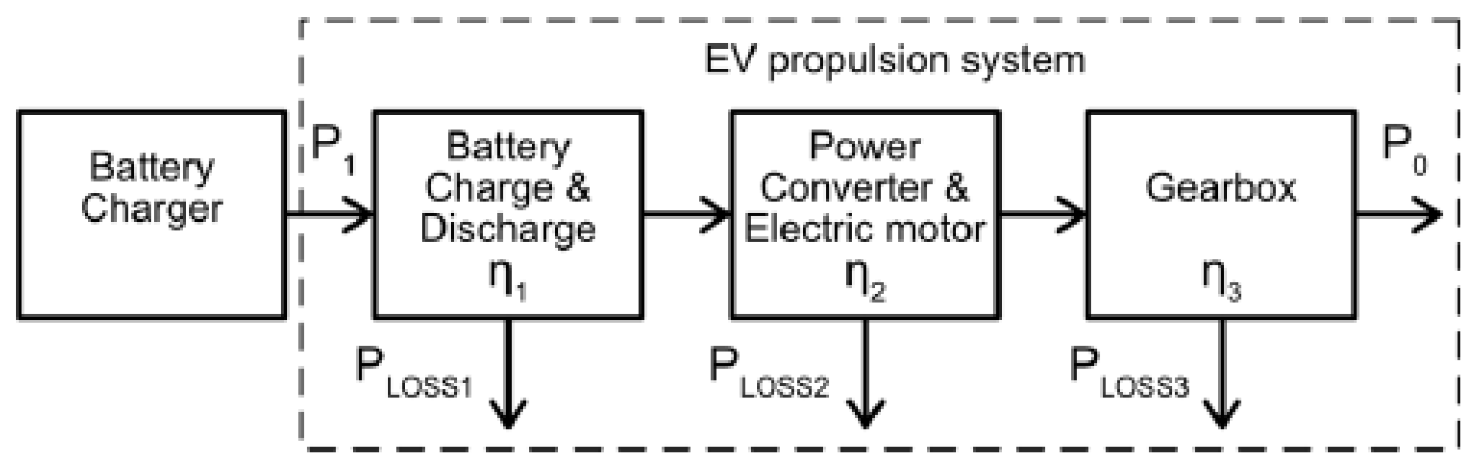
3.2. Overall Efficiency

The overall efficiency of an EV involves the efficiency of the battery, the power converter and the output of the electric motor, and the efficiency of the gearbox [21,22]. Figure 1 demonstrates the overall efficiency of the EV propulsion system and the efficiency equation is expressed in Equation (4).
Overall   efficiency   EV = P 0 P 1 = P 0 P 0 + P l o s s = η 1 η 2 η 3
where:
  • P1 = Input power
  • P0 = Output power
  • Ploss1 = Power losses in battery
  • Ploss2 = Power losses in converter and electric motor
  • Ploss3 = Power losses in gear box
  • η 1 = Battery efficiency
  • η 2 = Power converter and electric motor efficiency
  • η 3 = Gearbox efficiency.

3.3. Driving Cycle

The driving cycle is a speed–time graph produced by different countries to calculate vehicle exhaust emissions and energy consumption. This research used three continuous cycles of NEDC as shown in Table 1 for robustness purposes. This driving cycle is a combination of the Urban Driving Cycle and Extra-Urban Driving Cycle. For one cycle, the simulation time is 1184 s, with a maximum speed of 120 km/h and an average speed of 33.21 km/h. Figure 2 shows the NEDC driving pattern for three complete cycles.
Even though the Worldwide Harmonized Light Vehicles Test Procedure (WLTP) was introduced as a more accurate testing procedure than the NEDC, but the transition to WLTP is not fully complete in some regions. As a result, many vehicles on the road were tested under the NEDC. Researching EV driving patterns using NEDC allows for standardized testing and comparison while providing insights into the behaviour of existing EVs. It’s important to note that as EV technology advances and the transition to WLTP becomes more widespread, researchers are likely to shift towards using WLTP for their studies to capture the most up-to-date and accurate driving patterns and energy consumption data for EVs.

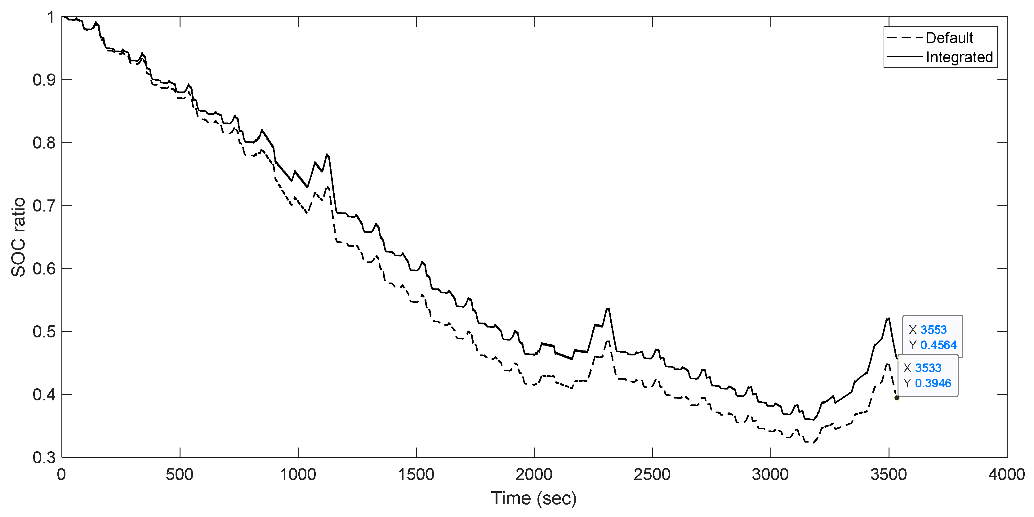
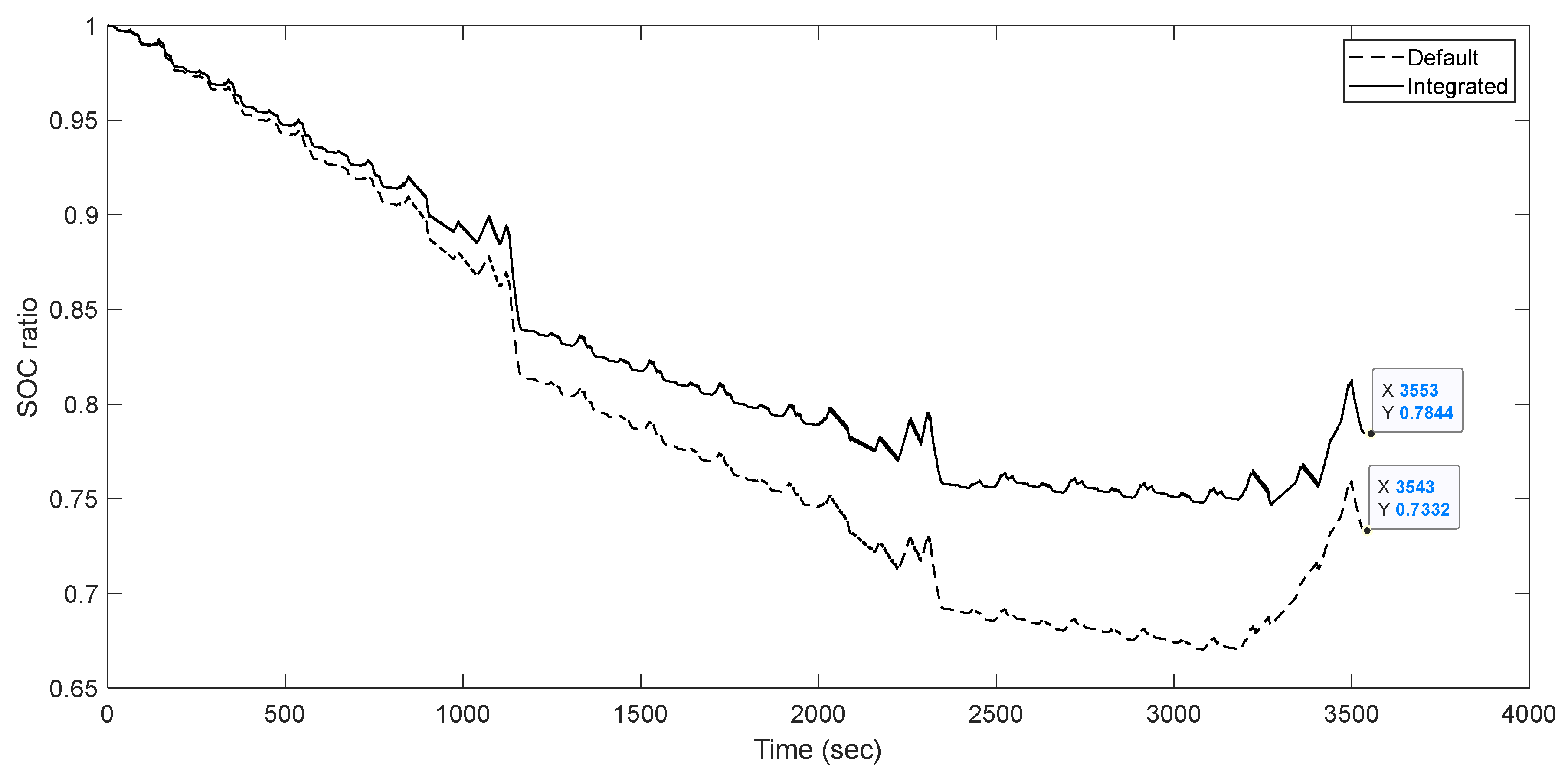
3.4. State of Charge

Battery safety can be guaranteed by keeping the battery’s SOC between 20% and 80% of maximum charge current. At a high SOC, the batteries are not allowed to be charged due to battery safety purposes. Therefore, the regenerative braking ratio should be reduced, and mechanical braking should be applied. When the value of the SOC drops to the middle range where the battery can be charged, then regenerative braking is increased to a certain level [23]. Next, when the SOC of the battery is at a lower level, the inner resistance of the battery increases to a high value, and it is inappropriate for the battery to be charged [24]. Discharging and charging processes for lithium-ion battery are formulated as follows:
Discharging formula ( i * > 0 );
f 1 ( i t , i * , i ) = E 0 K 0 ( Q Q i t ) i * K 0 ( Q Q i t ) i t + A 0 · exp ( B 0 · i t )
Charging formula ( i * < 0 );
f 1 ( i t , i * , i ) = E 0 K 0 ( Q i t + 0.1 Q ) i * K 0 ( Q Q i t ) i t + A 0 · exp ( B 0 · i t )
where E0 is constant voltage (V), A0 is the exponential voltage (V), B0 is the exponential capacity (Ah)−1, K0 is the polarisation resistance (Ω), i is the battery’s current (A), it is the extraction capacity (Ah), and i* is the low-frequency dynamic current (A). The SOC is used to indicate the remaining capacity of the battery, and it is the ratio of the remaining capacity of the battery to its total capacity [25,26].
S O C = Q r e s Q = 1 Q u s e d Q
where Qres represents the remaining battery capacity, Q is the total capacity, and Qused is the battery capacity that has been used. For a fully charged battery (100%), the SOC is equal to 1, while the SOC is equal to 0 for a depleted battery [13]. During high SOC, the charging should be limited to avoid overcharging. When the SOC drops below 80%, the battery accommodates high current. Therefore, when the SOC is higher than 0.8, appropriate regenerative braking is necessary to prevent the battery from overcharging.

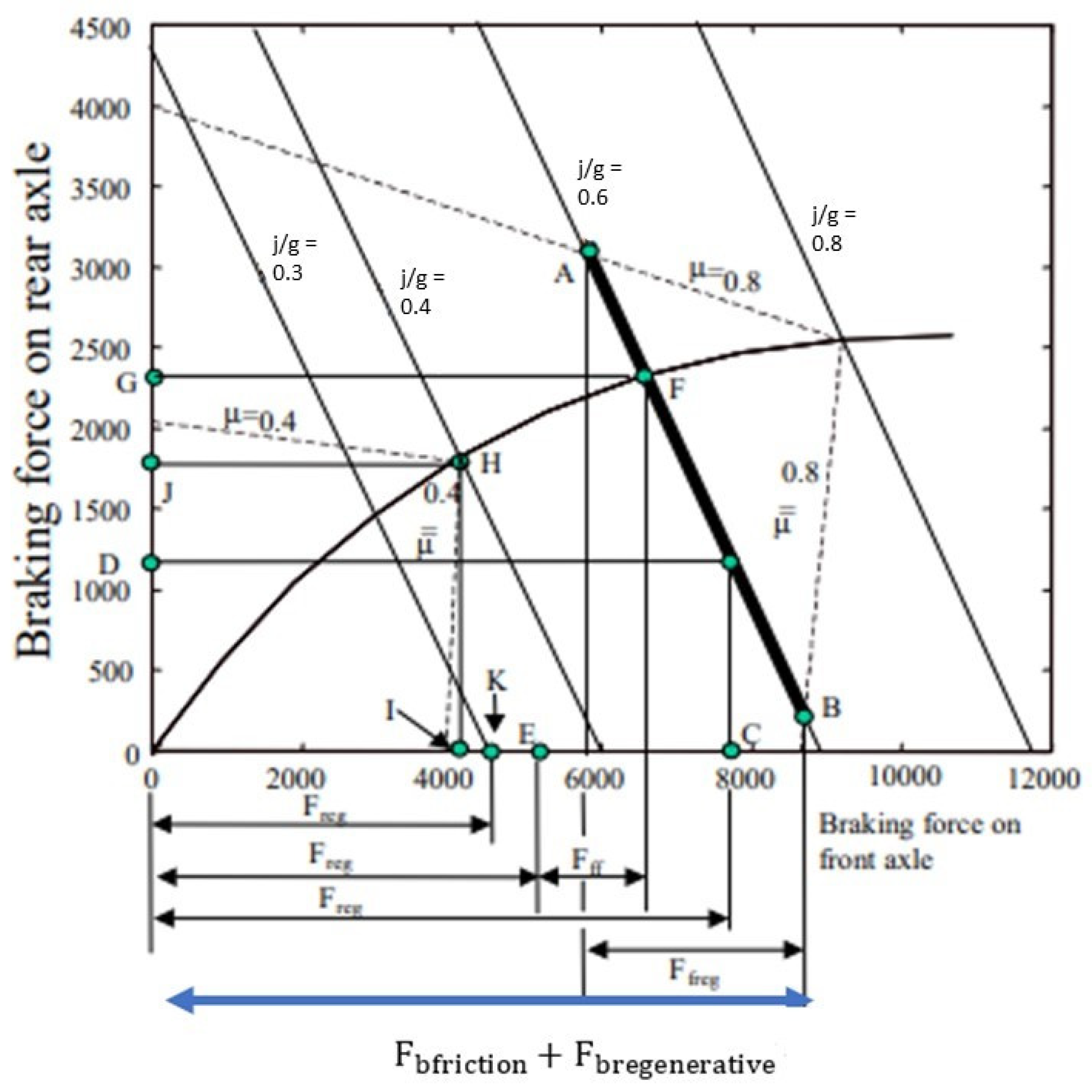
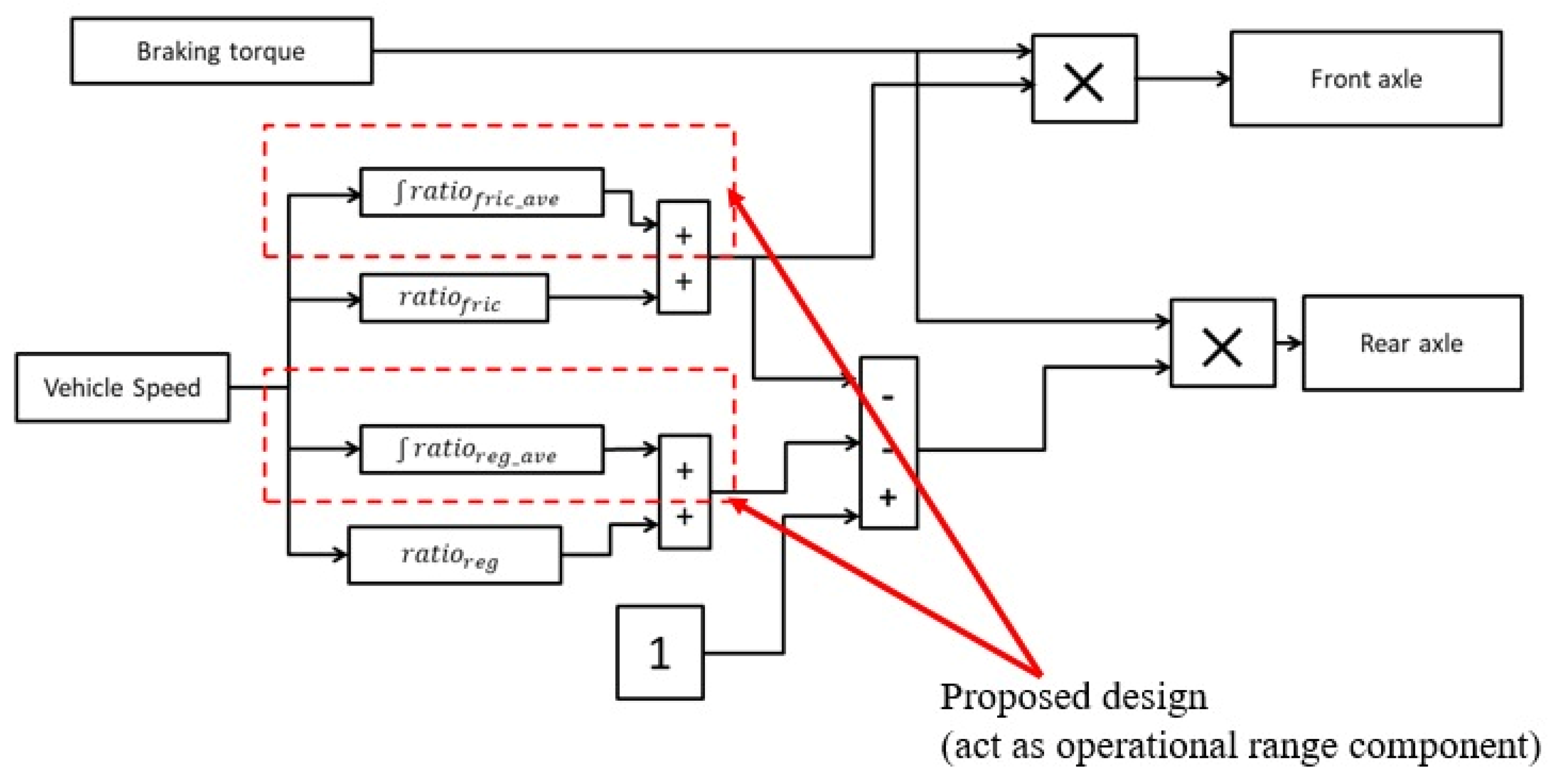
3.5. Braking Force Distribution
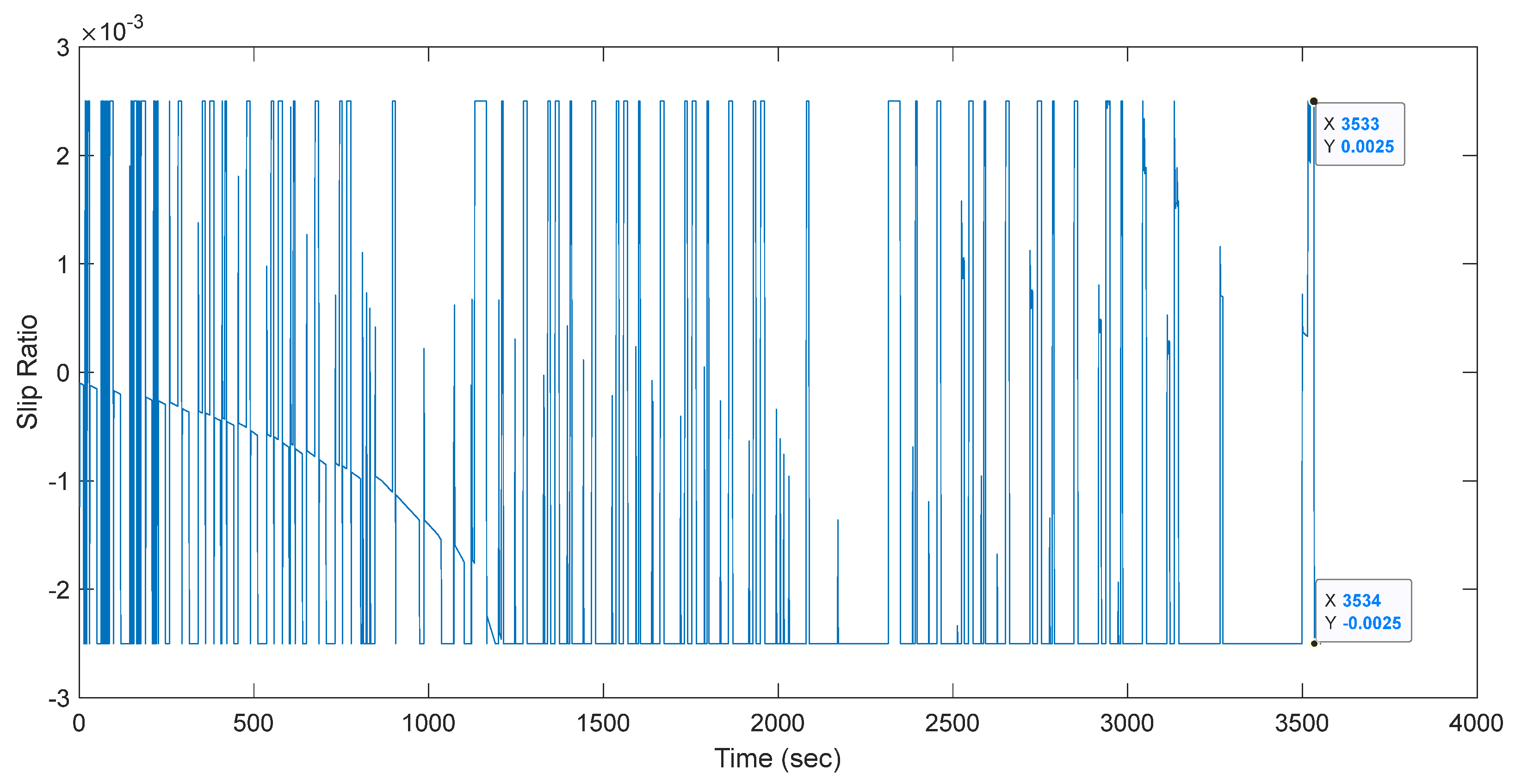
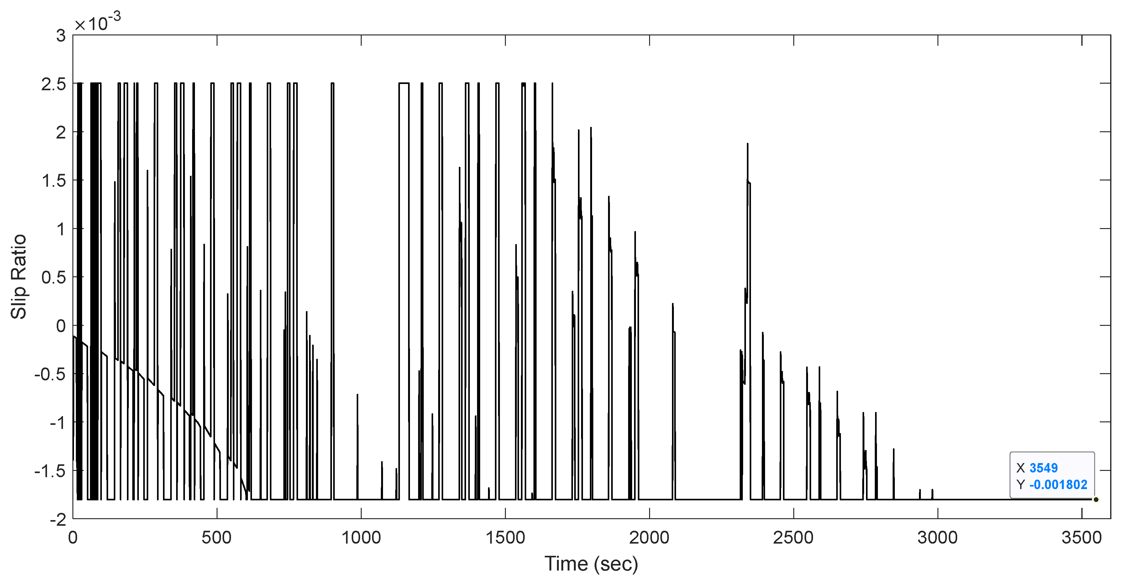
There are three types of conventional regenerative braking: braking with optimal driver’s feel, braking with optimal energy recovery, and parallel braking. The first strategy, which is braking with optimal driver’s feel, consists of a braking controller that controls the amount of braking force through the front and rear wheels. The main objective of this strategy is to minimise stopping distance and optimise the driver’s feel so that the regenerated energy can be increased [17]. When deceleration is less than a certain range, regenerative braking will only be applied on the rear axle. When the commanded deceleration increases, the braking force tracks the curve that represents the ideal force distribution. Moreover, to produce maximum energy recovery, the electric motor should be controlled properly. Another type of braking distribution is braking with optimal energy recovery. The concept of this strategy is to capture braking energy as much as possible under the condition that it satisfies the braking force demanded for a given deceleration.
Figure 3 illustrates that the distribution between the front and rear axles may vary in a certain range by satisfying F b f r i c t i o n + F b r e g e n e r a t i v e = m j where m is vehicle mass and j indicates the deceleration of the vehicle. This method needs an appropriate controller to meet the desired deceleration force distribution on the ideal braking curve to improve energy recovery [27].
Regenerative braking and mechanical braking that work together are collectively known as parallel braking. Mechanical braking force operates on the front and rear axles, while regenerative force is only effective on the front axle. Parallel braking is explained in Figure 4. It illustrates the operating principle, which applies regenerative braking only to the rear wheels. The parallel braking system employs conventional mechanical braking with a fixed front-to-rear brake force distribution. Regenerative braking adds additional braking force to the rear wheels, resulting in the distribution curve of the total braking force. The front and rear mechanical braking forces are proportional to the hydraulic pressure in the master cylinder. As the available regenerative braking force is a function of motor speed and almost no kinetic energy can be recovered at a low motor speed, the regenerative braking force at high vehicle decelerations is designed to be zero in order to maintain braking balance. Regenerative braking is effective when the required deceleration is less than this deceleration [28]. This research considers high vehicle deceleration at j/g = 0.83, as illustrated in Figure 4 below.
The parallel braking strategy distributes the braking force for regenerative and friction braking in relation to vehicle speed [29]. The regenerative braking force increases according to the speed. At a lower speed, only mechanical braking takes over for safety reasons. However, this method needs modifications to control regenerative braking according to motor speed and vehicle deceleration. Figure 5 shows the ADVISOR braking force distribution ratio.
The distribution between the front and rear axles is illustrated in Figure 6.
The total braking torque can be determined as follows [30]:
T t o t = T f r i c + T r e g
where Ttot is the total braking torque request, Tfric is the friction braking force of the front and rear axles, and Treg is the regenerative braking force of the rear axle.
T r = T r f r i c + T r r e g
The distribution for friction and regenerative braking at the rear axle can be expressed as:
T r g e n = T r · r a t i o r e g
T r f r i c = T r · ( 1 r a t i o f r i c r a t i o r e g )
where Tr_fric and Tr_reg represent the friction braking torque requested for friction and regenerative braking of the rear axle, respectively, and ratiofric and ratioreg denote the braking distribution coefficient for friction and regenerative braking, respectively.
Braking force distribution based on vehicle speed has fixed parameters, which lead to a less efficient braking distribution. A proper approach is needed to make the motor work in a high-efficiency region in order to increase travel distance and reduce electrical energy loss. This research introduced an integrated braking distribution by developing an average speed braking force distribution, as illustrated in Figure 7. The average braking force distribution was designed by considering the highest ratio of the regenerative braking coefficient at the most frequent speed level for the NEDC. Hence, the average braking force will act as the operating range for the optimisation of the default braking distribution.

3.6. Slip Ratio

Road adhesion is very low on slippery road surfaces. The optimal slip is not constant but varies along different roads. The tire–road contact condition can be determined with Equation (12), where µ is the friction coefficient, λ is the slip ratio, Fd is tire–road friction, and Fz is the wheel’s normal force.
µ ( λ ) = F d F z
The optimal longitudinal slip ratio at maximum adhesion is about 20% for any road adhesion coefficient. Therefore, the road adhesion could be set at a constant value of around 0.2 [31]. The slip ratio describes the difference between the wheel speed and the vehicle as formulated in Equation (13), where λ ,   λ d ,   ω , R, and V are the slip ratio, ideal slip ratio, wheel rotational speed, wheel radius, and vehicle longitudinal speed, respectively.
Λ = V ω R V ,           V 0
λ ˙ = V ˙ ( 1 λ ) R ω ˙ V = V ˙ V   λ + V ˙ V R ω ˙ V 0
V ˙ V   λ = f ( λ )
Let:
V ˙ V R ω ˙ V = u
Let | V ˙ V | < ρ where ρ is the upper limit of | V ˙ V | , thus:
λ ˙ = f ( λ ) + u
Tracking the error of the slip ratio yields the following equation:
e ˙ = λ d ˙ + λ ˙
Let the control laws, u and u 1 , for the slip ratio be set as follows:
u 1 = λ d ˙ + k e + ρ | e | e
u 1 = u
where k > 0 is positive constant, thus:
V ˙ V R ω ˙ V = λ d ˙ + k e + ρ | e | e
Lyapunov stability can be expressed as follows [32]:
V ( e ) = 1 2 e 2
V ˙ ( e ) = e e ˙ = k e 2 f ( λ ) e ρ | e | < k e 2 < 0
Based on Equation (24), it can be concluded that the system is stable when V ˙ ( e ) = 0 . Figure 8 shows the relationship between the friction coefficient and the slip ratio, where an increase in slip ratio may increase the adhesion coefficient until the maximum effective point d μ d λ = 0 is achieved, which is the point of optimal operation corresponding to the optimum slip ratio and maximum friction coefficient. In addition, λ < λ o p t is defined as a stable region, whereas λ > λ o p t is defined as an unstable region.

3.7. Sliding Mode Control

A sliding mode can offer many advantages, such as finite time convergence and robustness against uncertainties, making it a potential approach for mechanical systems. However, conventional SMC produces undesired chattering that may cause high-frequency dynamics and instability [32,33], as shown in Figure 9, where the error shown is the slip ratio’s error.
A typical form of the sliding surface is as follows, where x 1 is the reference speed and x 1 d is the actual speed.
e ( t ) = x 1 ( t ) x 1 d e ˙ = x 2 ( t ) }
The sliding surface is selected as follows:
S = e ˙ ( t ) + ν e ( t )
Substituting Equation (24) into Equation (25) yields the following:
S = e ˙ ( t ) + ν e ( t ) S = x 2 ( t ) + ν ( x 2 ( t ) x 1 d )
The time derivative when x 1 d is constant:
S ˙ ( t ) = x ˙ 2 ( t ) + ν x 1 ˙ ( t )
The conventional super-twisting algorithm control law can be expressed as:
u ( t ) = ν | S | 0.5 s g n ( S ) + θ
θ ˙ ( t ) = W s g n ( S )
where v and W are positive constants, while θ is the original discontinuous input from conventional SMC [34,35,36,37,38,39,40]. Traditional STSMC can be improved by adding gain scheduling for optimization to provide a faster response to the desired sliding surface and reduce steady-state error. The GSTSMC design is shown in Figure 10.
Therefore, the gain scheduling defined as K and the algorithm control law can be expressed as:
u ( t ) = K ( ν | S | 0.5 s g n ( S ) ) + θ
θ ˙ ( t ) = W s g n ( S )
The parameters of the controlled closed-loop system have been manually tuned ( v = 100 and W = 110) to achieve the best possible performance and remain unchanged for all scenarios to be performed. The Lyapunov stability method was followed as in [35]. Also available in [36,37] are references to the current state of the art regarding sliding mode control applications in power electronics.

4. Results and Discussion

This section discusses the efficiency of the proposed GSTSMC integrated with the overall efficiency, motor efficiency, distance, energy transmitted, vehicle speed, battery temperature, slip ratio, and SOC. Table 2 summarises the data for the default and integrated braking force distributions. The energy transmitted in the integrated design improved by 10.8%, and the energy loss during driving was reduced by 15 kJ.
Firstly, several different cases of NEDC were applied to validate the integrated regenerative braking control algorithm. The first case compared the default braking force with the integrated braking system without implementing any controller, as shown in Figure 11. The final SOC for the default braking force distribution (in the dotted line) is 0.3376, while for the integrated ratio (in the black line), the final SOC is 0.352, resulting in an SOC improvement of 2.5%.
Table 3 summarises the results and displays the efficiency of the braking system with conventional STSMC. The overall efficiency increased by 12.48%, the transmitted energy improved by 1.28%, and the energy loss during driving was reduced by 6606 kJ. In addition, there were no changes in distance, which means that the conventional STSMC could achieve three complete cycles of NEDC as requested.
Figure 12 demonstrates the NEDC driving cycle. There are a few points that undershoot by about 3 km/h and need further control law adjustment. Figure 13 shows that the operating temperature is 47 °C, and the slip ratio in Figure 14 is still within a stable region, which is less than 0.2 for a dry asphalt surface.
Figure 15 illustrates the SOC pattern with STSMC, and the improvement is 7.7%. Even though the final SOC of STSMC resulted in a higher ratio, the decrease in the SOC during driving is quite high. Therefore, some modifications to the SMC are needed to overcome this problem.
Figure 16 shows that the vehicle speed could track the requested speed better than conventional STSMC. Thus, it is proven that the GSTSMC is capable of eliminating the undershoot in conventional STSMC. Furthermore, the battery temperature is within the ideal working operation, which is 33.75 °C, as presented in Figure 17, and it is better than conventional STSMC.
Figure 18 illustrates that the vehicle slip ratio is maintained at less than 0.2 for stable conditions. Table 4 shows the performance of the GSTSMC. The overall efficiency achieved a significant improvement of 25.98%, the energy transmitted increased by 14.27%, and the energy loss was reduced by 87 kJ. According to the simulation results of the GSTSMC, the SOC could be saved by 0.7332 with the default braking strategy and improved to 0.78 with the integrated braking strategy. Furthermore, this design yielded a 6.4% improvement in SOC, as shown in Figure 19. In our analysis, it has been observed that a negative slip ratio occurs during braking or over-revving situations, where the actual rotational speed of the tire deviates from the theoretical speed. This negative slip ratio indicates either tire slippage or faster-than-expected rotation. Similarly, previous research has found that during severe deceleration, the tire rotates less than it would without slip, resulting in a consistently negative slip ratio for deceleration.
Based on the results in Table 2 and Table 3, the effectiveness of GSTSMC can be verified. Figure 20 summarises the comparison of the SOC curves of three braking force distributions. The dotted line represents the default braking control strategy with a final SOC of 0.3375. Meanwhile, the thick black line represents the SOC after the implementation of conventional STSMC, with a final SOC of 0.3941. The thin black line represents the results of the GSTSMC. The final SOC of GSTSMC is 0.7846, and it is still under the regenerative range (0.1–0.9), and thus gives a total improvement of 54%. As a result, if GSTSMC is adopted, more SOC will be saved.

5. Conclusions

This research proposed a RBS using integrated braking force distribution with GSTSMC, which was tested and verified in ADVISOR 2.0 software. Based on the simulation results in Table 3, it is proven that the GSTSMC with the proposed strategy has excellent control performance and good energy recovery. In order to improve the energy efficiency of electric vehicles, several parameters (i.e., overall efficiency, energy transmitted, energy loss during driving, and the SOC of the battery) have been considered. From the simulation results, the proposed control strategy could improve the SOC by 54%, overall efficiency by 25.98%, energy transmitted by 14.27%, and energy loss by 87 kJ with the consideration of the vehicle’s speed-tracking ability, battery temperature, and stability.

Author Contributions

Validation, M.A.M.R. and A.A.; formal analysis, A.K.G.; investigation, A.K.G.; writing—original draft, A.K.G.; writing—review and editing, M.K.H.; supervision, M.K.H. All authors have read and agreed to the published version of the manuscript.

Funding

This research received no external funding.

Data Availability Statement

The data that support the findings of this study are available from the corresponding author upon reasonable request.

Acknowledgments

The authors sincerely acknowledge Universiti Putra Malaysia (UPM) for the facility provided.

Conflicts of Interest

No potential conflict of interest was reported by the authors.

References

  1. Kuntanapreeda, S. Traction control of electric vehicles using sliding-mode controller with tractive force observer. Int. J. Veh. Technol. 2014, 2014, 829097. [Google Scholar] [CrossRef] [Green Version]
  2. Fajri, P.; Lee, S.; Prabhala, V.A.K.; Ferdowsi, M. Modeling and Integration of Electric Vehicle Regenerative and Friction Braking for Motor/Dynamometer Test Bench Emulation. IEEE Trans. Veh. Technol. 2016, 65, 4264–4273. [Google Scholar] [CrossRef]
  3. Kumar, C.S.N.; Subramanian, S.C. Cooperative control of regenerative braking and friction braking for a hybrid electric vehicle. Proc. Inst. Mech. Eng. Part D J. Automob. Eng. 2016, 230, 103–116. [Google Scholar] [CrossRef]
  4. Khorsravinia, K.; Hassan, M.K.; Rahman, R.Z.A.; Al-Haddad, S.A.R. Integrated OBD-II and mobile application for electric vehicle (EV) monitoring system. In Proceedings of the 2017 IEEE 2nd International Conference on Automatic Control and Intelligent System, Kota Kinabalu, Malaysia, 21 October 2017; Volume 2017, pp. 202–206. [Google Scholar] [CrossRef]
  5. Chen, J.; Liu, K.; Lan, F.; Liu, M. Braking Stability-Oriented Regenerative Braking Control Strategy of Twin Motor 4WD Electric Vehicle. DEStech Trans. Eng. Technol. Res. 2017, 2017, 58–65. [Google Scholar] [CrossRef] [PubMed] [Green Version]
  6. Lv, C.; Zhang, J.; Li, Y.; Yuan, Y. Regenerative Braking Control Algorithm for an Electrified Vehicle Equipped with a by-Wire brake System; SAE International: Warrendale, PA, USA, 2014; Volume 1. [Google Scholar] [CrossRef]
  7. Zheng, L.; Shi, Z.; Luo, Y.; Kang, J. A Study of Energy Recovery System during Braking for Electric Vehicle. In 2016 6th International Conference on Applied Science, Engineering and Technology; Atlantis Press: Amsterdam, The Netherlands, 2016; pp. 8–13. [Google Scholar] [CrossRef] [Green Version]
  8. Shewate, S.; Kumbhalkar, M.A.; Sonawane, Y.; Salunkhe, T.; Savant, S. Modelling And Simulation of Regenerative Braking System for Light Commercial Vehicle—A Review. IOSR J. Mech. Civ. Eng. 2018, 8, 52–56. [Google Scholar]
  9. Bai, Z.F.; Li, S.X.; Cao, B.G. H∞ Control Applied to Electric Torque Control for Regenerative Braking of an Electric Vehicle. J. Appl. Sci. 2005, 5, 1103–1107. [Google Scholar] [CrossRef] [Green Version]
  10. Palanivel, P.; Alemayehu, H.; Chandramouli, B.; Hiremath, R. Design and Analysis of BLDC Motor Drive Based on Fuzzy-PID Controller. Int. J. Electr. Eng. Technol. 2020, 11, 281–290. [Google Scholar] [CrossRef]
  11. Zhang, H.; Xu, G.; Li, W.; Zhou, M. Fuzzy logic control in regenerative braking system for electric vehicle. In Proceedings of the 2012 IEEE International Conference on Information and Automation, Shenyang, China, 6–8 June 2012; pp. 588–591. [Google Scholar] [CrossRef]
  12. Mei, P.; Yang, S.; Xu, B.; Sun, K. A Fuzzy Sliding-Mode Control for Regenerative Braking System of Electric Vehicle. In Proceedings of the 2021 7th International Conference on Control, Automation and Robotics (ICCAR), Singapore, 23–26 April 2021; pp. 397–401. [Google Scholar] [CrossRef]
  13. Canciello, G.; Russo, A.; Guida, B.; Cavallo, A. Supervisory Control for Energy Storage System Onboard Aircraft. In Proceedings of the 2018 IEEE International Conference on Environment and Electrical Engineering and 2018 IEEE Industrial and Commercial Power Systems Europe (EEEIC/I&CPS Europe), Palermo, Italy, 12–15 June 2018; pp. 1–6. [Google Scholar] [CrossRef]
  14. Cavallo, A.; Canciello, G.; Russo, A. Supervised Energy Management in Advanced Aircraft Applications. In Proceedings of the 2018 European Control Conference (ECC), Limassol, Cyprus, 12–15 June 2018; pp. 2769–2774. [Google Scholar] [CrossRef]
  15. Chu, S.; Xie, Z.; Wong, P.K.; Li, P.; Li, W.; Zhao, J. Observer-based gain scheduling path following control for autonomous electric vehicles subject to time delay. Veh. Syst. Dyn. 2022, 60, 1602–1626. [Google Scholar] [CrossRef]
  16. Allagui, N.Y.; Salem, F.A.; Aljuaid, A.M. Artificial Fuzzy-PID Gain Scheduling Algorithm Design for Motion Control in Differential Drive Mobile Robotic Platforms. Comput. Intell. Neurosci. 2021, 2021, 5542888. [Google Scholar] [CrossRef]
  17. Mehrdad, E.; Yimin, G.; Sebastian, E.G.; Ali, E. Modern Electric, Hybrid Electric, and Fuel Cell Vehicles; CRC Press: Boca Raton, FL, USA, 2005. [Google Scholar]
  18. Nam, K.; Hori, Y.; Lee, C. Wheel slip control for improving traction-ability and energy efficiency of a personal electric vehicle. Energies 2015, 8, 6820–6840. [Google Scholar] [CrossRef] [Green Version]
  19. Eckert, J.J.; Silva, L.C.A.; Costa, E.S.; Santiciolli, F.M.; Dedini, F.G.; Corrêa, F.C. Electric vehicle drivetrain optimisation. IET Electr. Syst. Transp. 2017, 7, 32–40. [Google Scholar] [CrossRef]
  20. Yamsani, A. Gradeability for Automobiles. IOSR J. Mech. Civ. Eng. 2014, 11, 35–41. [Google Scholar] [CrossRef]
  21. Niksa, Ć.; Damir, V.; Vraži, M. Overall Efficiency in Electric Road Vehicles. Safety Eng. 2011, 8, 51–56. [Google Scholar] [CrossRef]
  22. Josef, B.; Zvolský, T. Experimental study of electric vehicle gearbox efficiency. In MATEC Web of Conferences; EDP Sciences: Les Ulis, France, 2018; Volume 4, p. 02004. [Google Scholar]
  23. Rajendran, S.; Spurgeon, S.; Tsampardoukas, G.; Hampson, R. Intelligent Sliding Mode Scheme for Regenerative Braking Control. IFAC PapersOnLine 2018, 51, 334–339. [Google Scholar] [CrossRef]
  24. Zhang, Z.; Xu, G.; Li, W.; Zheng, L. Regenerative Braking for Electric Vehicle based on Fuzzy Logic Control Strategy. In Proceedings of the 2010 2nd International Conference on Mechanical and Electronics Engineering, Kyoto, Japan, 1–3 August 2010; Volume 1, pp. 319–323. [Google Scholar] [CrossRef]
  25. Anowar, M.H.; Roy, P. A Modified Incremental Conductance Based Photovoltaic MPPT Charge Controller. In Proceedings of the 2019 International Conference on Electrical, Computer and Communication Engineering (ECCE), Cox’sBazar, Bangladesh, 7–9 February 2019. [Google Scholar] [CrossRef]
  26. Vyroubal, P.; Maxa, J.; Kazda, T. Simulation of the behavior of the lithium ion battery. Adv. Mil. Technol. 2014, 9, 107–115. [Google Scholar]
  27. Gao, Y.; Chen, L.; Ehsani, M. Investigation of the Effectiveness of Regenerative Braking for EV and HEV. SAE Trans. 2018, 108, 3184–3190. [Google Scholar]
  28. Sangtarash, F.; Esfahanian, V.; Nehzati, H.; Haddadi, S.; Bavanpour, M.A.; Haghpanah, B. Effect of Different Regenerative Braking Strategies on Braking Performance and Fuel Economy in a Hybrid Electric Bus Employing CRUISE Vehicle Simulation. SAE Int. J. Fuels Lubr. 2009, 1, 828–837. [Google Scholar] [CrossRef] [Green Version]
  29. Guo, J.; Wang, J.; Cao, B. Regenerative braking strategy for electric vehicles. In Proceedings of the 2009 IEEE Intelligent Vehicles Symposium, Xi’an, China, 3–5 June 2009; pp. 864–868. [Google Scholar] [CrossRef]
  30. Zhao, X. Braking torque distribution for hybrid electric vehicles based on nonlinear disturbance observer. Proc. Inst. Mech. Eng. Part D J. Automob. Eng. 2019, 233, 3327–3341. [Google Scholar] [CrossRef]
  31. Xu, G.; Xu, K.; Zheng, C.; Zhang, X.; Zahid, T. Fully Electrified Regenerative Braking Control for Deep Energy Recovery and Maintaining Safety of Electric Vehicles. IEEE Trans. Veh. Technol. 2016, 65, 1186–1198. [Google Scholar] [CrossRef]
  32. Zhao, Y.; Zhang, J.; Li, C.; He, C. Sliding Mode Control Algorithm for Regenerative Braking of an Electric Bus with a Pneumatic Anti-lock Braking System. In IOP Conference Series: Materials Science and Engineering; IOP Publishing: Bristol, UK, 2019. [Google Scholar] [CrossRef]
  33. Zheng, Y.; Liu, J.; Liu, X.; Fang, D.; Wu, L. Adaptive Second-Order Sliding Mode Control Design for a Class of Nonlinear Systems with Unknown Input. Math. Probl. Eng. 2015, 2015, 319495. [Google Scholar] [CrossRef] [Green Version]
  34. Heng, C.T.; Jamaludin, Z.; Hashim, A.Y.B.; Rafan, N.A.; Abdullah, L.; Salleh, M.R.; Arep, H. Desing and Analysis of Super Twisting Sliding Mode Control for Machine Tools. J. Teknol. 2016, 3, 25–29. [Google Scholar]
  35. Kruse, O.; Mukhamejanova, A.; Mercorelli, P. Super-Twisting Sliding Mode Control for Differential Steering Systems in Vehicular Yaw Tracking Motion. Electronics 2022, 11, 1330. [Google Scholar] [CrossRef]
  36. Fallaha, C.J.; Saad, M.; Kanaan, H.Y.; Al-Haddad, K. Sliding-mode robot control with exponential reaching law. IEEE Trans. Ind. Electron. 2011, 58, 600–610. [Google Scholar] [CrossRef]
  37. Ghazali, A.K.; Hassan, M.K.; Radzi, M.A.M.; As’arry, A. Electric vehicle with sliding mode control super-twisting control strategy. J. Phys. Conf. Ser. 2020, 1432, 012023. [Google Scholar] [CrossRef]
  38. Alkharasani, B.A.; Hassan, M.K.; Akmeliawati, R.; Zafira, R.; Ahmed, S.A. PID-sliding surface based sliding mode controller for anti-lock braking system of electric vehicle. Adv. Sci. Lett. 2016, 22, 2734–2737. [Google Scholar] [CrossRef] [Green Version]
  39. Ghazali, A.K.; Hassan, M.K.; Radzi, M.A.M.; As’arry, A. Integrated braking force distribution for electric vehicle regenerative braking system. Pertanika J. Sci. Technol. 2020, 28, 173–182. [Google Scholar] [CrossRef]
  40. Ghazali, A.K.; Hassan, M.K.; Mohd Radzi, M.A.; As’arry, A. Sliding mode control optimization method using fuzzy-gain scheduling for rgenerative braking system. J. Adv. Res. Dyn. Control Syst. 2020, 12, 1504–1509. [Google Scholar] [CrossRef]
Figure 1. Individual components of the EV propulsion system’s efficiency [22].
Energies 16 04561 g001
Figure 2. Three complete cycles of NEDC.
Energies 16 04561 g002
Figure 3. Optimal braking energy recovery.
Energies 16 04561 g003
Figure 4. Parallel braking distribution.
Energies 16 04561 g004
Figure 5. ADVISOR braking force distribution.
Energies 16 04561 g005
Figure 6. Braking force distribution based on speed.
Energies 16 04561 g006
Figure 7. Integrated braking force distribution.
Energies 16 04561 g007
Figure 8. Slip ratio curve.
Energies 16 04561 g008
Figure 9. Sliding mode control surface.
Energies 16 04561 g009
Figure 10. Super-twisting SMC with gain scheduling.
Energies 16 04561 g010
Figure 11. SOC without controller.
Energies 16 04561 g011
Figure 12. Vehicle speed of conventional STSMC.
Energies 16 04561 g012
Figure 13. Battery temperature of conventional STSMC.
Energies 16 04561 g013
Figure 14. Slip ratio of conventional STSMC.
Energies 16 04561 g014
Figure 15. SOC performance for conventional STSMC.
Energies 16 04561 g015
Figure 16. Vehicle speed of GSTSMC.
Energies 16 04561 g016
Figure 17. Battery temperature of GSTSMC.
Energies 16 04561 g017
Figure 18. Slip ratio of GSTSMC.
Energies 16 04561 g018
Figure 19. SOC of GSTSMC.
Energies 16 04561 g019
Figure 20. Comparison of integrated braking force distribution.
Energies 16 04561 g020
Table 1. NEDC characteristics.
ParametersValue
Distance10.93 km
Maximum speed120 km/h
Average speed33.21 km/h
Maximum acceleration1.06 m/s2
Maximum deceleration−1.39 m/s2
Number of stops13
Table 2. Comparison between default and integrated braking force distributions (without controller).
ParametersDefaultIntegratedImprovement
Overall efficiency0.4330.433-
Motor efficiency0.80.8-
Distance (km)32.832.8-
Energy transmitted (kJ)4573506910.8%
Energy loss during driving (kJ)2550253515 kJ
Table 3. Conventional STSMC performance.
ParametersDefaultIntegratedImprovement
Overall efficiency0.4850.54612.58%
Motor efficiency0.830.83-
Distance (km)3333-
Energy transmitted (kJ)119 × 105121 × 1051.68%
Energy loss during driving (kJ)72,81366,2076606 kJ
Table 4. GSTSMC performance.
ParametersDefaultIntegratedImprovement
Overall efficiency0.740.8312.16%
Motor efficiency0.860.86-
Distance (km)32.632.6-
Energy transmitted (kJ)4977568714.27%
Energy loss during driving (kJ)2770285787 kJ
Disclaimer/Publisher’s Note: The statements, opinions and data contained in all publications are solely those of the individual author(s) and contributor(s) and not of MDPI and/or the editor(s). MDPI and/or the editor(s) disclaim responsibility for any injury to people or property resulting from any ideas, methods, instructions or products referred to in the content.

