Article

Experimental Study on the Preparation of Hydrogen-Rich Gas by Gasifying of Traditional Chinese Medicine Residue in a DFB Based on Calcium Looping

Shandong Provincial Key Laboratory of Biomass Gasification Technology, Energy Institute, Qilu University of Technology (Shandong Academy of Sciences), Jinan 250014, China
*
Author to whom correspondence should be addressed.
Energies 2023, 16(11), 4434; https://doi.org/10.3390/en16114434
Submission received: 23 April 2023 / Revised: 26 May 2023 / Accepted: 28 May 2023 / Published: 31 May 2023
(This article belongs to the Special Issue Solid Looping Process for Low Carbon Energy)

Abstract

:
Using traditional Chinese medicine residue biomass as the raw material and industrial limestone as a carbon absorbent, this paper investigates the production of hydrogen-rich synthesis gas in a pilot-scale calcium looping dual fluidized bed (DFB) system. The study focuses on analyzing the distribution characteristics of temperature and pressure, as well as the operation and control methods of the DFB system. The effects of reaction temperature, material layer height (residence time), water vapor/biomass ratio (S/B), and calcium/carbon molar ratio (Ca/C) on gasification products are examined. The experimental results demonstrate that as the temperature (600–700 °C), S/B ratio (0.5–1.5), Ca/C ratio (0–0.6), and other parameters increase, the gas composition shows a gradual increase in the volume content of H2, a gradual decrease in the volume content of CO, and an initial increase and subsequent decrease in the volume content of CH4. Within the range of operating conditions in this study, the optimal conditions for producing hydrogen-rich gas are 700 °C, an S/B ratio of 1.5, and a Ca/C ratio of 0.6. Furthermore, increasing the height of the material layer in the gasification furnace (residence time) enhances the absorption of CO2 by the calcium absorbents, thus promoting an increase in the volume content of H2 and the carbon conversion rate in the gas.

1. Introduction

DFB technology and the classic two-step chemical chain reaction process are mutually compatible, making the chemical chain reactor predominantly a cyclic dual bed structure. DFB gasification technology allows for the separation of pyrolysis gasification and semi-coke combustion of solid fuels (such as coal, biomass, etc.). It utilizes high-temperature circulating bed materials to provide heat for the gasifier, producing medium-to-high calorific value fuel gas without the need for pure oxygen or oxygen-rich gasification agents. Extensive research has been conducted on this technology [1]. Chemical chain technology involves the participation of solid-phase carrier materials carrying target substances (such as hydrogen, nitrogen, carbon, oxygen, etc.) in corresponding gas–solid reactions [2]. In 2001, Chalmers University of Technology in Sweden successfully operated the world’s first reaction device based on the chemical chain combustion process using gas fuel methane [3], demonstrating the feasibility of this technology. Subsequently, chemical chain technology has gained significant attention, and research institutions worldwide have constructed chemical chain reactors of various types and scales [4,5,6,7,8,9,10]. The commonly studied carrier materials are oxygen carriers and carbon carriers. Carbon carrier chemical chains are primarily employed for capturing carbon dioxide or enhancing hydrogen production by adsorbing carbon dioxide through carbon carriers [11,12,13,14,15].
Currently, research on chemical chain carrier materials primarily focuses on two strategies: (1) Utilizing natural ores as carrier materials and integrating them with other related industries to achieve synergistic energy and production processes. For instance, the calcification chain process can be combined with cement production by using deactivated carbon carriers in the calcification chain process for cement production or utilizing the substantial heat generated in cement production to regenerate carbon carriers [16]. Similarly, the iron-based chemical chain process can be integrated with iron and steel metallurgy production by utilizing slag from iron and steel production as an oxygen carrier in the chemical chain process [17]; (2) Enhancing the reaction activity of natural ores by incorporating additives to obtain improved and stable carrier materials. Density functional theory (DFT), molecular modeling-assisted experimental verification, and other methods are employed to gain a deeper understanding of the microscopic properties of materials. These insights assist in reverse designing the artificial preparation of carrier materials with durable performance, stable structure, and high cost-efficiency [18,19,20].
The advancement of the hydrogen energy industry has created vast application opportunities for hydrogen production through biomass gasification based on calcium looping technology, thus driving its development. Key factors influencing the hydrogen production process from calcium-based chemical chain biomass gasification include temperature, residence time, S/B, and Ca/C, among others. However, in a DFB system, parameters such as the gasification reaction temperature and residence time of the raw material cannot be directly controlled; instead, they are achieved by adjusting the circulation rate of bed materials and the height of the gasification furnace material layer through primary air, return air, and other means. The DFB system operates as an intricately interactive and coupled system of various processes, making it challenging to independently adjust a single parameter. This study focuses on investigating the operation and regulation characteristics of a pilot-scale DFB system. Additionally, it employs inexpensive and readily available industrial limestone as a carbon absorber to explore the hydrogen production characteristics and influencing factors of calcium-based chemical chain biomass gasification. The ultimate goal is to further promote the industrialization and development of DFB biomass gasification technology for the synthesis of hydrogen-rich syngas in the calcium looping process.

2. Materials and Methods

2.1. Physical Model

The DFB gasification process typically comprises three main processes: pyrolysis, gasification, and combustion. Based on the primary reactions involved, the entire DFB system can be divided into four distinct regions: I, II, III, and IV (refer to Figure 1) [21,22,23]. Ideally, each region is responsible for accomplishing the corresponding reactions described below [24,25,26].
Zone I, also known as the raw material layer, is situated in the middle section of the gasification furnace reaction zone. Within this region, biomass raw materials are subjected to heating and drying by high-temperature circulating bed materials. Simultaneously, the biomass undergoes pyrolysis reactions, leading to the production of pyrolysis gas, semi-coke, and tar.
The reaction equation is as follows:
Biomass → Char + Tar + Gases (CO, H2, CH4, CO2, H2O, CnHm)
Zone II is positioned in the lower section of the raw material layer, where the semi-coke reacts with the gasification agent (air or water vapor) as follows:
2C + O2 → 2CO
C + H2O → CO + H2
Zone III is situated above the raw material layer. Within this region, the primary reactions encompass gas component transformation and tar cracking, which can be summarized as follows:
CO + H2O → CO2 + H2
Tar → CO + H2 + CO2 + CH4 + CnHm
Zone IV is located in the combustion furnace, where semi-coke and air undergo combustion reactions:
C + O2 → CO2

2.2. Experimental Device

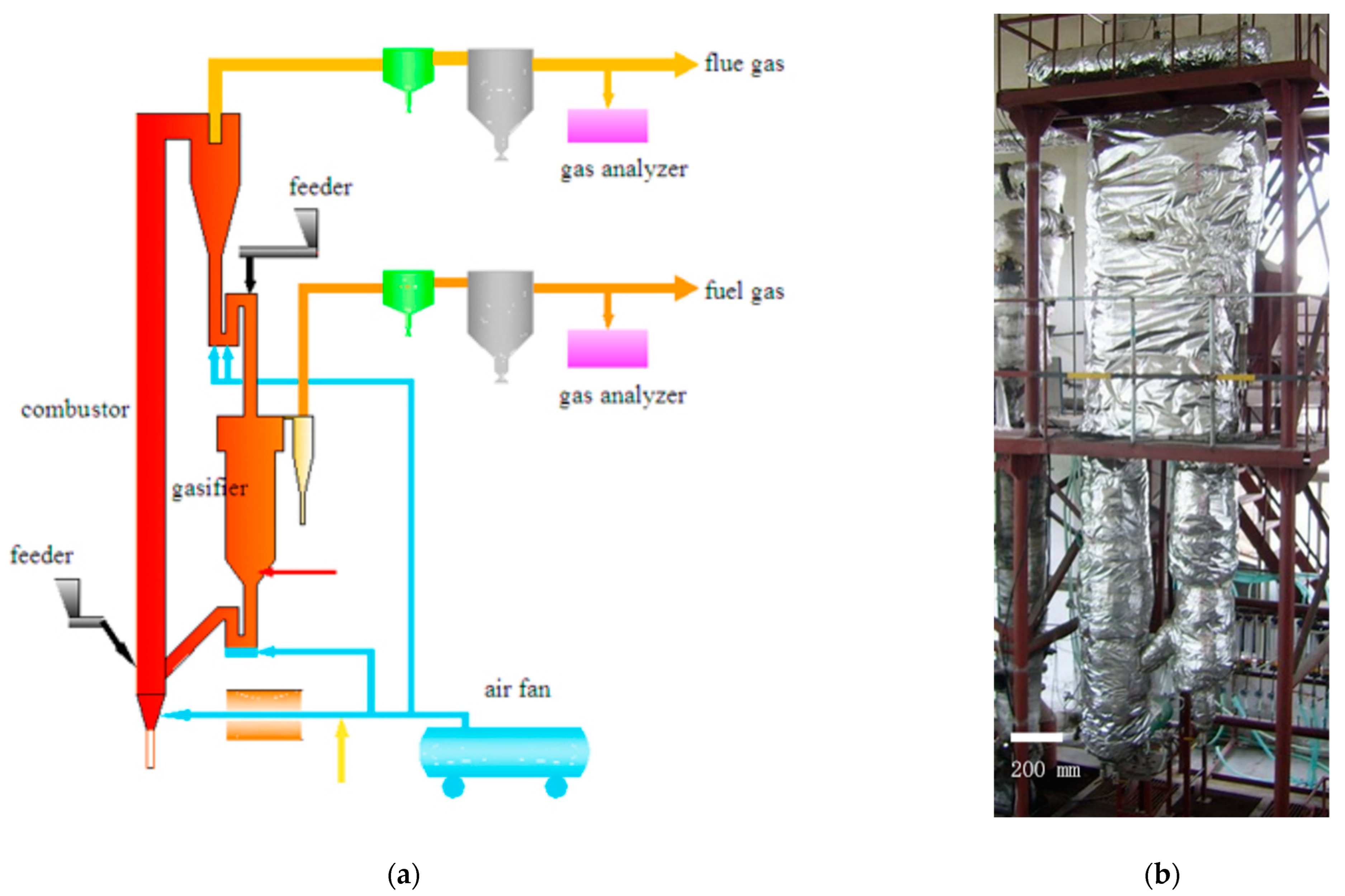
The DFB gasification system diagram and physical image are illustrated in Figure 2a,b, respectively. The combustion furnace measures 3000 mm in height and has an inner diameter of 100 mm. The gasifier, on the other hand, has a height of 1500 mm and an inner diameter of 200 mm. Both the combustion furnace and the gasifier are connected through two return feeders, namely the upper and lower feeders. Feeding ports are present on the upper part of the combustion furnace and the gasification furnace. The DFB reactor is constructed using a heat-resistant alloy, Cr25Ni20, and is covered with aluminum silicate fiber insulation. The gas analyzer model is Gasboard-3100P. CO, CO2, and CH4 are measured using NDIR (Non-Dispersive Infrared) technology, H2 is measured using TCD (Thermal Conductivity Detector) technology, and O2 is measured using electrochemical methods. The gas analyzer is arranged in the tail flue.
The temperature measurement points, pressure measurement points, and feeding port positions for the combustion furnace are presented in Table 1. Similarly, Table 2 displays the temperature measurement points, pressure measurement points, feeding ports, and gasification agent inlet positions for the gasifier.
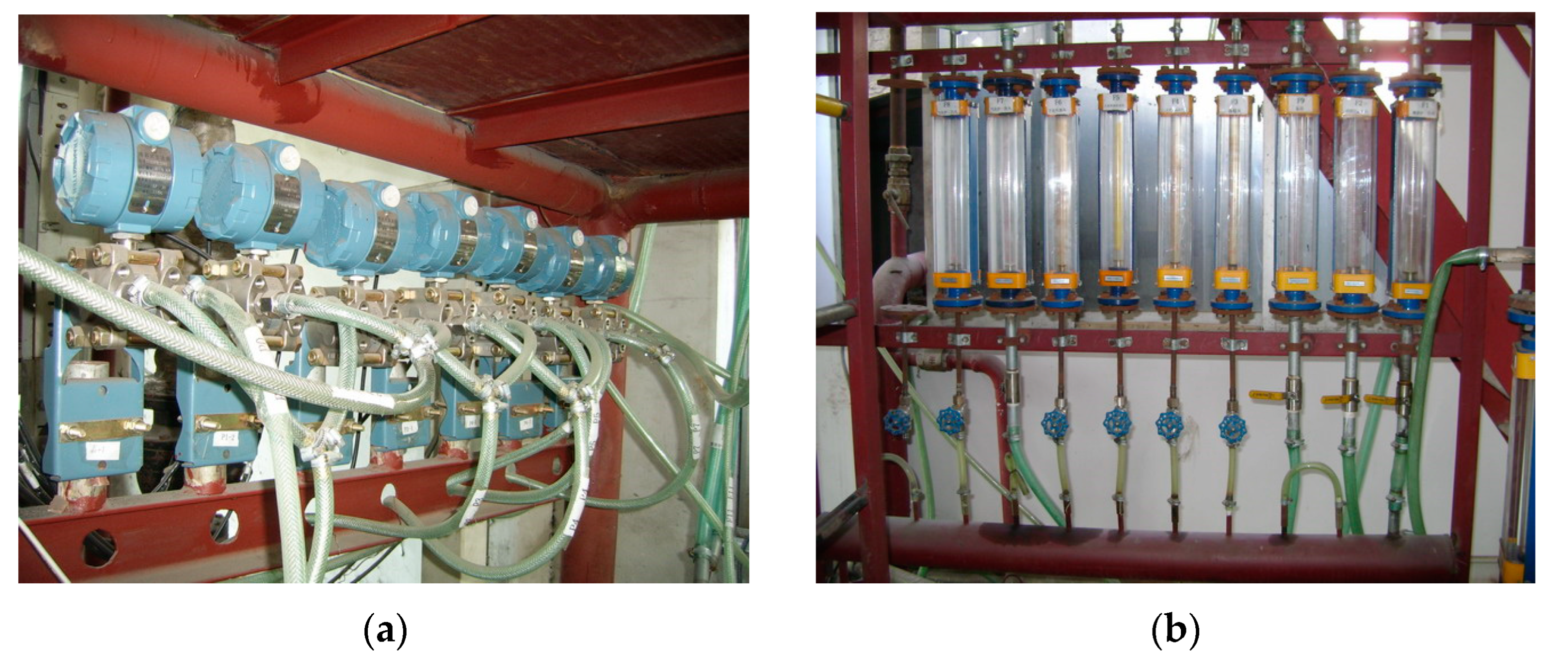
The temperature is measured using a K-type thermocouple with a tolerance/error tolerance of ±0.75; the differential pressure signals are measured and transmitted through pressure transmitters (Figure 3a). The frequency regulator controls the feeding motor’s frequency. All measurement results are converted into standard electrical signals and inputted into a computer for real-time data collection, display, and recording. The air volumes are measured using a rotameter (Figure 3b) and recorded manually.

2.3. Raw Materials

The biomass raw materials utilized in this study were Chinese herb residues (CHR) sourced from a pharmaceutical company in Shandong Province. The initial moisture content of the CHR was approximately 70%. Following natural drying, crushing, and screening, particles with an average size of about 5 mm and a moisture content of about 5% were selected as the experimental raw materials. The air-dried basis properties of the material are presented in Table 3.

3. Results and Discussion

3.1. Temperature and Pressure Characteristics of DFB

3.1.1. Temperature Characteristics

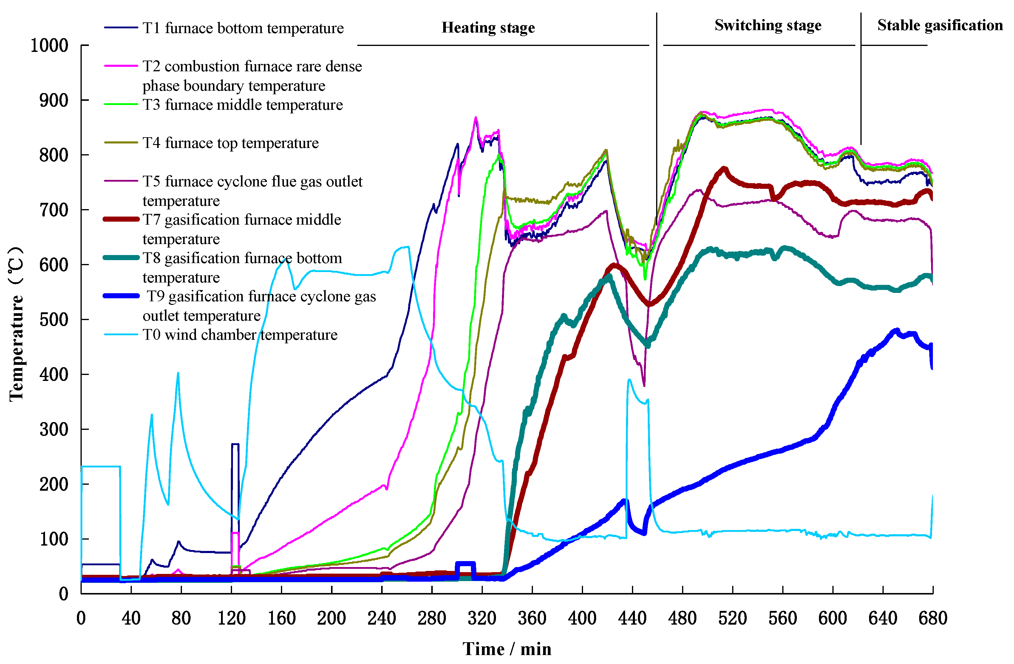
The experimental process consists of four stages, as follows: (1) Combustion furnace heating stage: The dense phase zone of the combustion furnace is heated by the hot flue gas from the natural gas burner. The temperature gradually rises to 400 °C, and the fuel quantity increases with the temperature until the average temperature of the combustion furnace reaches 800 °C and stabilizes. (2) Gasifier heating stage: The upper loop seal’s loose air and fluidized air are activated, allowing high-temperature bed material to enter the gasifier and heat it up. Simultaneously, the lower loop seal’s loose air and fluidized air are activated to return the bed material from the gasifier to the combustion furnace, thus establishing bed material circulation. The gasifier temperature increases to above 600 °C and stabilizes. (3) Transition from combustion to gasification: Biomass raw materials are gradually fed into the gasifier through a feeder while the fuel feed volume in the combustion furnace gradually decreases. This gradual adjustment facilitates the transition from a combustion state to a gasification state. (4) Stable gasification stage: The gasification agent (air or water vapor) continuously flows into the gasification furnace, and air continuously flows into the combustion furnace. Within the gasifier, biomass raw materials react with the gasification agents to produce gas and semi-coke. The semi-coke enters the combustion furnace to heat the circulating bed material, while the high-temperature circulating bed material enters the gasifier to provide the necessary energy for gasification. Throughout this stage, the system’s temperature, pressure, and gas composition remain stable. Figure 4 depicts the temperature variation curve of the system.
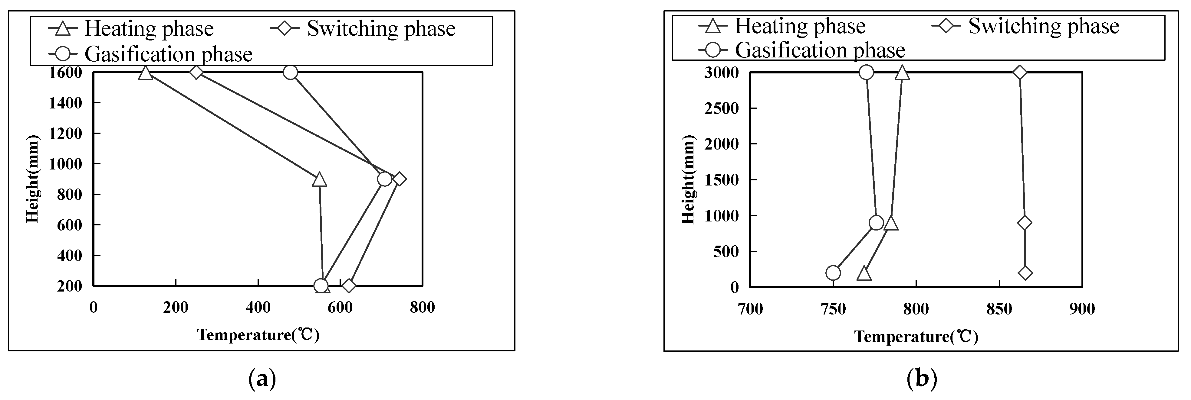
As depicted in Figure 4 and Figure 5a, the temperature distribution within the gasifier during gasification follows the pattern: T7 > T8 > T9. The maximum temperature difference observed during stable operation exceeds 200 °C, which can be attributed to the gasifier’s operational characteristics. The middle section of the gasifier serves as the high-temperature bed material mixing area, functioning as the primary gasification reaction zone. The bottom section, on the other hand, is another significant area for gasification reactions. Here, biomass particles absorb heat and undergo pyrolysis during the settling process, leading to a lower temperature at the bottom. The top section represents the gas phase zone, which exhibits a lower temperature due to heat dissipation and secondary cracking. In contrast, the combustion furnace demonstrates a uniform temperature distribution along its height direction. In the combustion state, the temperature difference between the bottom and top of the combustion furnace is 28 °C. During gasification, the temperature difference between the top and bottom of the combustion furnace reduces to 17 °C, as illustrated in Figure 5b. This uniform temperature distribution can be attributed to the utilization of a circulating fluidized bed combustion method in the combustion furnace, along with a high circulation rate (with a calculated circulation rate of over 40 under gasification conditions). Consequently, the concentration of circulating bed material within the furnace remains significantly high.

3.1.2. Pressure Variation Characteristics

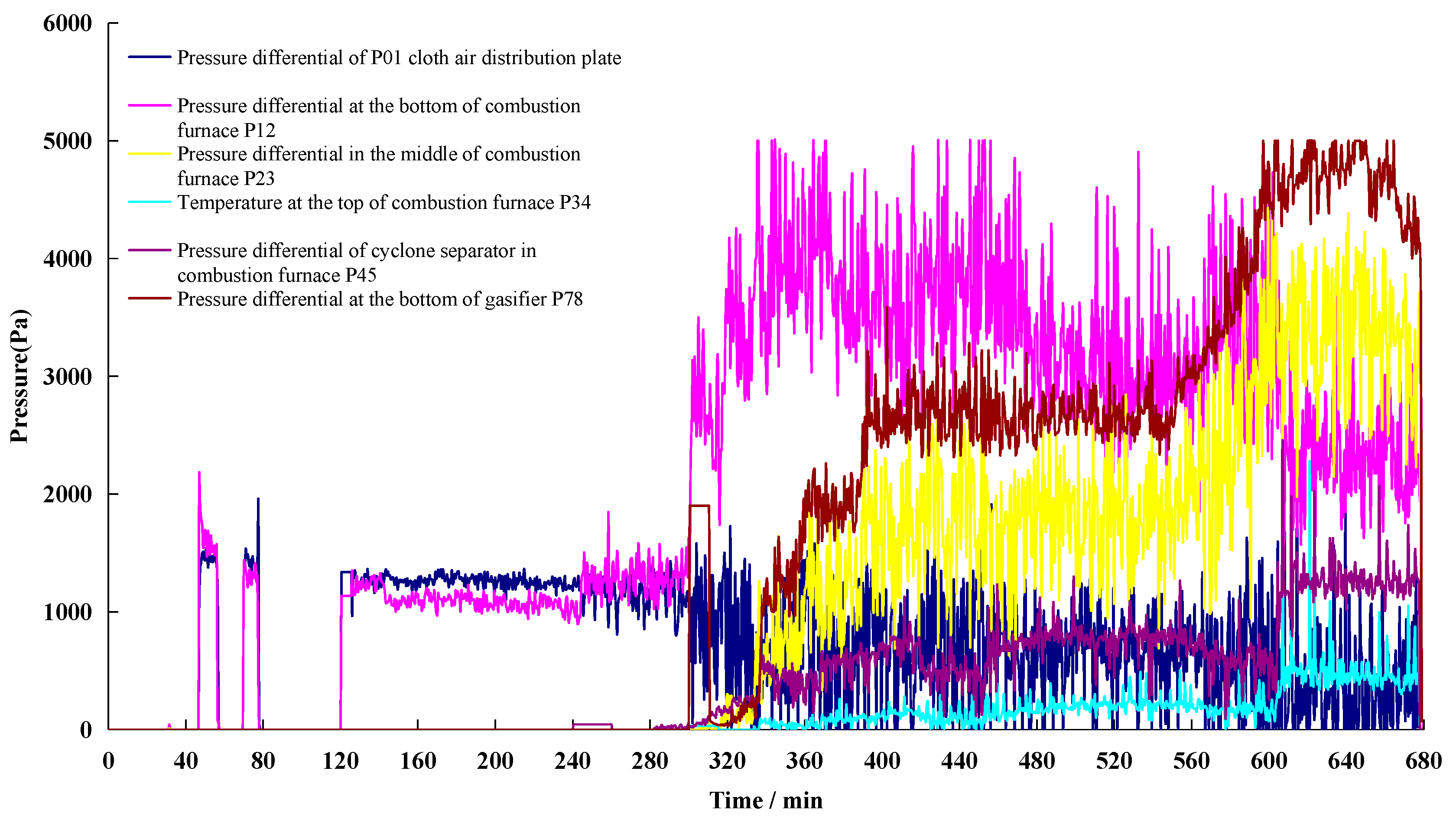
Figure 6 illustrates the variation curve of pressure difference at different positions during the heating, switching, and gasification processes in the DFB system. Pressure difference is a crucial parameter for assessing the operational status of a DFB system. It reflects important factors that influence gasification characteristics, such as the fluidized state of the combustion and gasification furnaces, bed material circulation, and material layer height. The DFB system exhibits distinct pressure distribution characteristics during different operational stages. During the heating stage, as the air volume increases, the bed material in the combustion furnace transitions from a critical fluidized state to a circulating fluidized state, resulting in a sudden increase in pressure difference (P12) in the dense phase zone of the combustion furnace. The gradual increase in pressure difference (P34) at the top of the combustion furnace indicates a corresponding increase in the amount of circulating bed material, which influences the temperature of the gasifier; in the subsequent stages, the pressure difference (P12) in the dense phase area of the combustion furnace abruptly decreases, while the pressure difference in the middle of the combustion furnace (P23), the pressure difference at the top of the combustion furnace (P34), and the pressure difference in the gasification furnace (P78) experience a sudden increase. This indicates that the combustion furnace enters a rapid fluidized transition state, and the material layer in the gasification furnace increases. By adjusting the wind speed, the height of the material layer inside the gasifier can be modified, which is reflected in the pressure difference (P78). The height of the gasification furnace material layer directly influences the residence time of biomass in the gasification furnace, which subsequently affects the characteristics of the gasification products. The height of the gasification furnace material layer can be adjusted by the air volume of the lower return feeder and is reflected by the pressure difference (P78). The distribution patterns of gas composition, cold gas efficiency (CGE) (Equation (7)), and carbon conversion rate (Equation (8)) were investigated in gasification furnaces with material layer heights of 100 mm, 200 mm, and 400 mm, operating at a temperature of 650 °C, Ca/C ratio of 0.4, and S/B ratio of 1. The findings are depicted in Figure 7 [27,28,29]. The experimental results demonstrate that the height of the gasification furnace material layer has a significant impact on the gas composition, CGE, and carbon conversion rate. Increasing the height of the material layer in the gasification furnace (thus extending the residence time) positively influences the volume content of H2 and the carbon conversion rate in the gas. This can be attributed to the longer residence time for raw material gasification and increased contact time between the gas and calcium absorbent, which enhances carbon capture.
CGE = LHV   of   product   gas   [ kJ kg ] LHV   of   fuel   feedstock   fed   into   the   system   [ kJ kg ]
C conversion ( % ) = Gasified   carbon   in   the   product   gas   [ g ] Carbon   of   feedstock   fed   into   the   system   [ g ]
where LHV represents the lower heating value.

3.2. Gasification Performance of DFB

This section focuses on examining the impact of gasifier temperature, S/B ratio, and Ca/C ratio parameters on the characteristics of producing hydrogen-rich syngas through the gasification of traditional Chinese medicine residue in the calcification chain.

3.2.1. Influence of Temperature

Gasification temperature is a critical factor that significantly impacts the efficiency and effectiveness of biomass gasification processes. In this study, traditional Chinese medicine residue was employed as the raw material, while industrial limestone served as the bed material. The experimental conditions included a Ca/C ratio of 0.4 and an S/B ratio of 1.
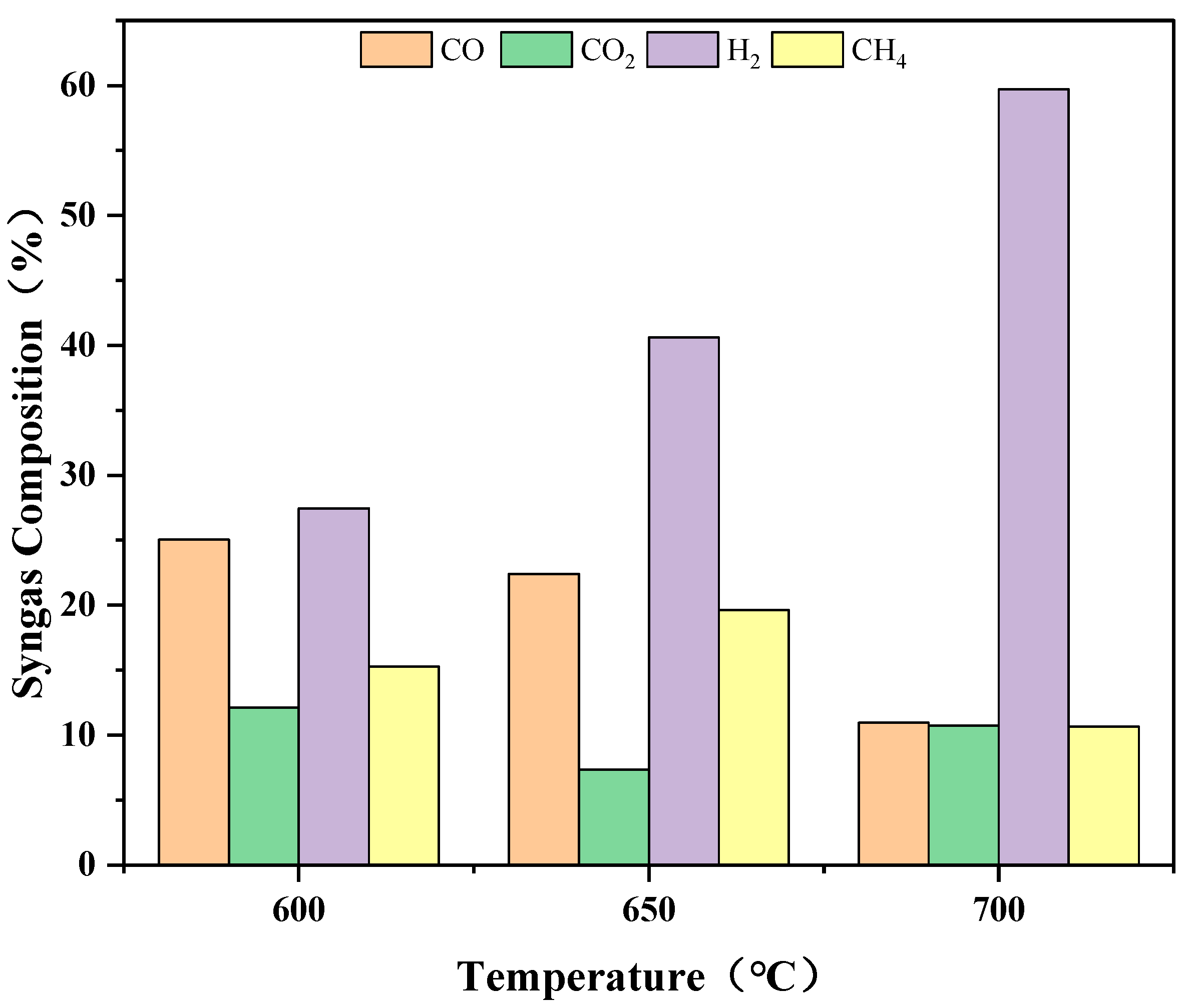
The impact of temperature on biomass gasification products is illustrated in Figure 8, where the gasifier’s middle temperature (T7) is set at 600 °C, 650 °C, or 700 °C. The results demonstrate significant variations in gas composition with temperature changes. Firstly, the volume fraction of H2 in the gas increases notably with temperature, rising from 27.45% at 600 °C to 59.7% at 700 °C. This increase can be attributed to the breaking of hydrocarbon bonds in organic macromolecules as the temperature rises, resulting in a higher concentration of volatile components. Secondly, the volume fraction of CO2 initially decreases and then increases with increasing temperature, ranging from 12.14% at 600 °C to 10.74% at 700 °C. The initial decrease may be attributed to the absorption of a considerable amount of CO2 by calcium oxide, which promotes the progress of the water–gas shift reaction and methane reforming reaction, leading to increased H2 production. As the temperature continues to rise, the reaction rate between calcium oxide and CO2 is impeded, resulting in a slower increase in the volume fraction of CO2. Thirdly, the volume fraction of CO gradually decreases with temperature, ranging from 25.03% at 600 °C to 10.95% at 700 °C. The presence of calcium oxide facilitates the significant reduction in CO’s volume fraction as it is consumed in the water–gas shift reaction. Lastly, the volume fraction of CH4 initially increases and then decreases with temperature, ranging from 15.27% at 600 °C to 10.65% at 700 °C. The increase in CH4 concentration is primarily attributed to the pyrolysis of biomass raw materials and tar cracking, as their generation rate in the reactor surpasses that of the methane reforming reaction. The reaction system inside the gasifier is the coupling and equilibrium of various reaction subsystems, such as tar cracking reaction, water gas shift reaction, and methane generation and reforming reaction, and is influenced by the chemical reaction rate. Thus, a perfect explanation for experimental phenomena is not easy. The increase in CO2 at 650 °C to 700 °C may be influenced by chemical reaction kinetics factors.
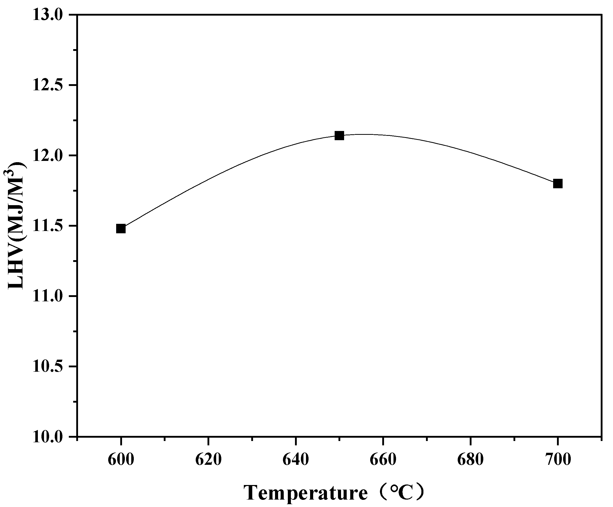
The calorific value of the gas exhibits a characteristic trend with temperature variations, as depicted in Figure 9. It follows an initial increase and then a decrease pattern as the temperature rises. The range of relatively high calorific values is observed between 640 °C and 660 °C. This behavior can be attributed to the changes in gas composition at different temperatures. Between 600 °C and 650 °C, the volume fraction of CO decreases while the fractions of H2 and CH4 continue to increase. This shift in gas composition leads to an overall increase in the total gas calorific value. In this temperature range, the increase in H2 content, combined with CH4, contributes significantly to the higher calorific value of the gas. However, as the temperature exceeds 650 °C, both the CH4 and CO fractions start to decrease while the H2 content continues to increase. It is important to note that CH4 is a gas with a high calorific value, and its presence significantly influences the overall calorific value of the gas. Consequently, after surpassing 660 °C, the total calorific value of the gas begins to decline due to the decrease in the CH4 fraction.

3.2.2. The Effect of S/B

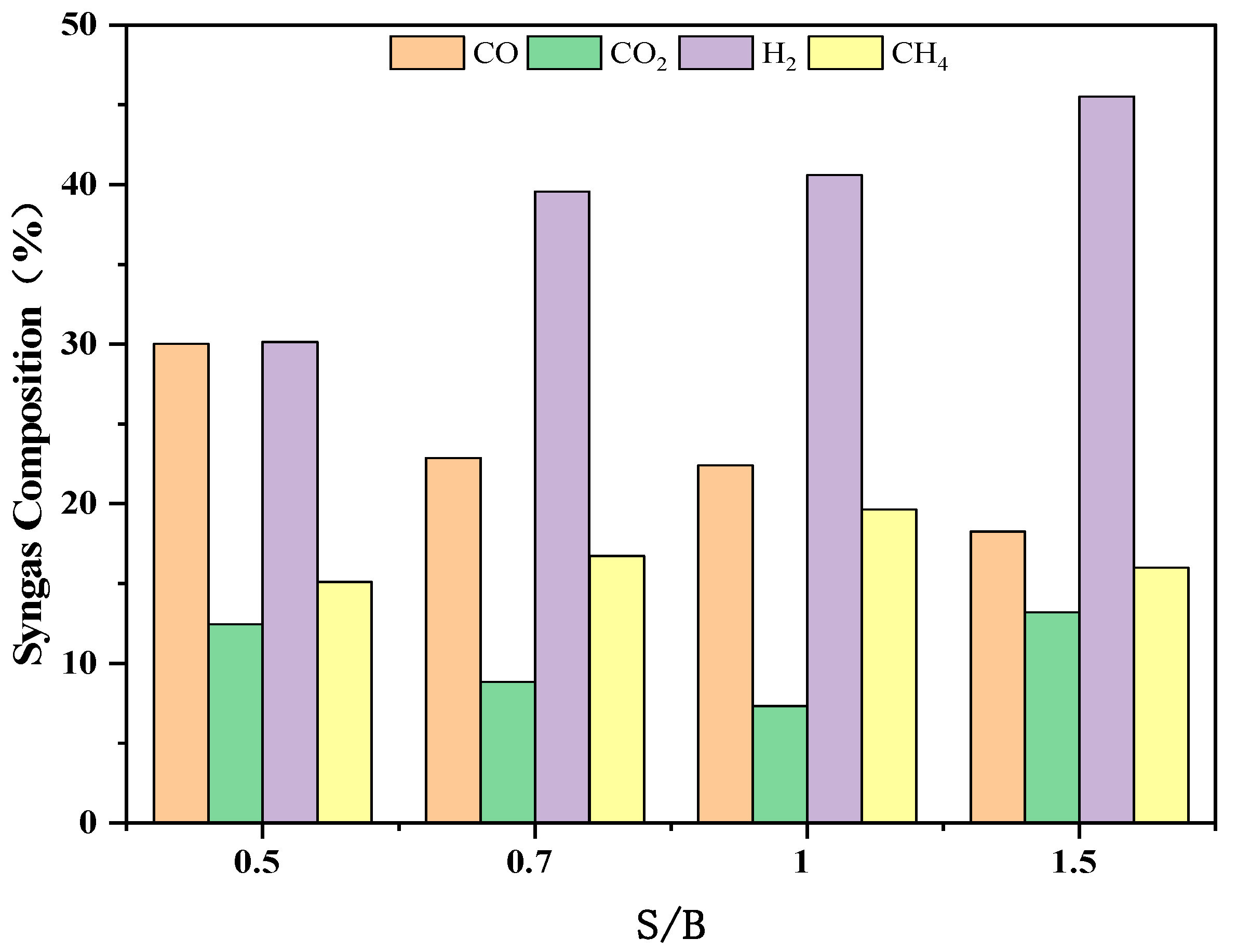
The addition of gasification agents plays a crucial role in influencing gas production, as they directly react with biomass pyrolysis gas and semi-coke. Different types of gasification agents, such as air, water vapor, and oxygen, can be used. In this experiment, the gasification temperature in the fluidized bed was maintained at 650 °C, and the Ca/C ratio was 0.4. By varying the amount of added water vapor, the impact of S/B ratios ranging from 0.5 to 1.5 on biomass gasification products was investigated.
Figure 10 illustrates the results of this study. As the S/B ratio increases from 0.5 to 1.5, the volume fraction of H2 continues to rise, ranging from 30.14% to 45.51%. In contrast, the volume fraction of CO gradually decreases with increasing S/B, declining from 30.04% to 18.27%. The volume fraction of CO2 exhibits an initial decrease followed by an increase as S/B increases, ranging from 12.46% to 13.19%. Similarly, the volume fraction of CH4 initially increases and then decreases with increasing S/B, reaching a peak value of 16.01% when S/B is at its highest (1.5).
These results can be explained by the role of water vapor in promoting the water–gas shift reaction and its interaction with carbon and CO. With an increase in the S/B ratio, the concentration of H2 in the gas gradually increases while the volume fraction of CO decreases. This is due to the reaction between CO and water vapor, which generates H2 and CO2. The rate of CO generation is lower than its consumption rate, resulting in a decrease in its volume fraction as the water vapor flow rate increases. When the S/B ratio increases from 0.5 to 1, the CO2 generated by the water–gas shift reaction is absorbed by CaO in the reactor, leading to a gradual decrease in the volume fraction of CO2. However, once the adsorption capacity of CaO reaches saturation, the volume fraction of CO2 starts to increase.

3.2.3. The Effect of Ca/C

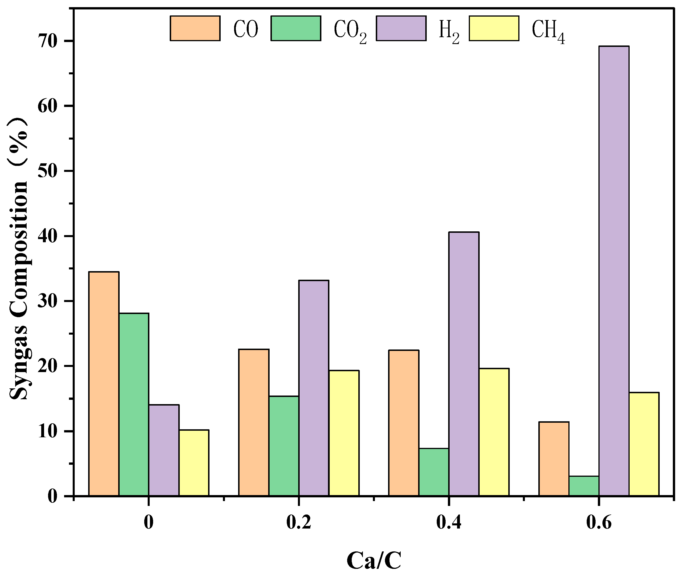
To investigate the influence of industrial limestone on gas composition, experiments were conducted at a temperature of 650 °C with a fixed S/B ratio of 1. Different Ca/C molar ratios of 0, 0.2, 0.4, and 0.6 were used. The results are presented in Figure 11. As the Ca/C ratio increases from 0 to 0.4, the volume fraction of H2 increases from 14.06% to 40.6%. Furthermore, as the Ca/C ratio further increases from 0.4 to 0.6, the volume fraction of H2 continues to rise, reaching 69.17%. Conversely, the volume fraction of CO gradually decreases with the increase in the Ca/C ratio. When Ca/C is 0, the volume fraction of CO2 is 28.12%. However, as Ca/C increases from 0 to 0.6, the volume fraction of CO2 decreases significantly to 3.08%. Regarding CH4, its volume fraction initially increases from 10.19% (Ca/C = 0) to 19.64% (Ca/C = 0.4) and then slightly decreases to approximately 15% (Ca/C = 0.6). These results align with the findings of Bishnu et al. [30], who investigated the impact of CaO on gas composition and gas yield. They observed that the removal of carbon dioxide by CaO reduces its partial pressure, leading to the promotion of the water–gas shift reaction and ultimately improving hydrogen yield.

4. Conclusions

This study aims to develop a cost-effective and efficient calcium-based DFB biomass hydrogen production technology for industrial-scale implementation. The experimental investigation focuses on examining the effects of temperature, S/B ratio, and Ca/C ratio on hydrogen production characteristics using industrial limestone, which is readily available and economical as a carbon absorber. The control of air flow in the system enables the adjustment of reaction temperature and residence time of the raw materials, allowing for optimization of the gasification process. By manipulating operating parameters such as the S/B ratio and the Ca/C ratio, an effective technical process for biomass gasification hydrogen production is established. This process yields hydrogen-rich synthesis gas with a high-volume fraction of approximately 70% H2. Moreover, the composition of the synthesis gas can be flexibly adjusted within a wide range by modifying process parameters, facilitating its suitability for diverse downstream applications.
The stable and reliable operation of the experimental system provides a feasibility verification for large-scale industrial hydrogen production from biomass using cost-effective industrial limestone as a raw material in the calcification chain DFB. This research paves the way for the potential realization of commercial-scale biomass hydrogen production, offering an environmentally friendly and economically viable pathway for hydrogen production.

Author Contributions

Conceptualization, L.Y. and X.F.; methodology, L.Y. and X.F.; validation, X.Z., L.Y. and X.F.; formal analysis, X.Z. and L.Y.; investigation, X.Z. and L.Y.; resources, X.Z. and L.Y.; data curation, X.Z. and L.Y.; writing—original draft preparation, X.Z.; writing—review and editing, X.L.; visualization, X.Z.; supervision, X.L.; project administration, L.Y.; funding acquisition, L.Y. All authors have read and agreed to the published version of the manuscript.

Funding

This research was funded by Shandong Provincial Natural Science Foundation (grant number: ZR2020KE042).

Data Availability Statement

Not applicable.

Acknowledgments

Authors appreciate the copyright holder: © Elsevier B.V.

Conflicts of Interest

The authors declare no conflict of interest. The funders had no role in the design of the study, in the collection, analyses, or interpretation of data, in the writing of the manuscript, or in the decision to publish the results.

References

  1. Song, G.; Lü, Q.; Qi, L. Experimental Research on Coal Gasification Characteristics in Single and Dual Circulating Fluidized Beds. Proc. CSEE 2009, 29, 24–29. [Google Scholar]
  2. Zhu, X.; Imtiaz, Q.; Donat, F.; Müller, C.R.; Li, F. Chemical looping beyond combustion—A perspective. Energy Environ. Sci. 2020, 13, 772–804. [Google Scholar] [CrossRef]
  3. Anders, L.; Leckner, B.; Mattisson, T. A fluidized-bed combustion process with inherent CO2 separation; application of chemical-looping combustion. Chem. Eng. Sci. 2001, 56, 3101–3113. [Google Scholar]
  4. Siddig, A.; Wang, W.; Abdalazeez, A. A brief review for chemical looping combustion as a promising CO2 capture technology: Fundamentals and progress. Sci. Total Environ. 2021, 764, 142892. [Google Scholar]
  5. Alalwan, H.A.; Alminshid, A.H. CO2 capturing methods: Chemical looping combustion (CLC) as a promising technique. Sci. Total Environ. 2021, 788, 147850. [Google Scholar] [CrossRef] [PubMed]
  6. Nguyen, N.M.; Alobaid, F.; Dieringer, P.; Epple, B. Biomass-based chemical looping gasification: Overview and recent developments. Appl. Sci. 2021, 11, 7069. [Google Scholar] [CrossRef]
  7. Lin, Y.; Wang, H.; Wang, Y.; Huo, R.; Huang, Z.; Liu, M.; Wei, G.; Zhao, Z.; Li, H.; Fang, Y. Review of biomass chemical looping gasification in China. Energy Fuels 2020, 34, 7847–7862. [Google Scholar] [CrossRef]
  8. Goel, A.; Moghaddam, E.M.; Liu, W.; He, C.; Konttinen, J. Biomass chemical looping gasification for high-quality syngas: A critical review and technological outlooks. Energy Convers. Manag. 2022, 268, 116020. [Google Scholar] [CrossRef]
  9. Samprón, I.; de Diego, L.F.; García-Labiano, F.; Izquierdo, M.T.; Adánez, A.A.J. Biomass Chemical Looping Gasification of pine wood using a synthetic Fe2O3/Al2O3 oxygen carrier in a continuous unit. Bioresour. Technol. 2020, 316, 123908. [Google Scholar] [CrossRef]
  10. Hu, Q.; Shen, Y.; Chew, J.W.; Ge, T.; Wang, C.-H. Chemical looping gasification of biomass with Fe2O3/CaO as the oxygen carrier for hydrogen-enriched syngas production. Chem. Eng. J. 2020, 379, 122346. [Google Scholar] [CrossRef]
  11. Abanades, J.C.; Murillo, E.; Fernandez, J.R.; Grasa, G.; Martínez, I. New CO2 capture process for hydrogen production combining Ca and Cu chemical loops. Environ. Sci. Technol. 2010, 44, 6901–6904. [Google Scholar] [CrossRef] [PubMed]
  12. Di Giuliano, A.; Gallucci, K. Sorption enhanced steam methane reforming based on nickel and calcium looping: A review. Chem. Eng. Process.-Process Intensif. 2018, 130, 240–252. [Google Scholar] [CrossRef]
  13. Weimer, T.; Berger, R.; Hawthorne, C.; Abanades, J.C. Lime enhanced gasification of solid fuels: Examination of a process for simultaneous hydrogen production and CO2 capture. Fuel 2008, 87, 1678–1686. [Google Scholar] [CrossRef]
  14. Connell, D.P.; Lewandowski, D.A.; Ramkumar, S.; Phalak, N.; Statnick, R.M.; Fan, L.-S. Process simulation and economic analysis of the Calcium Looping Process (CLP) for hydrogen and electricity production from coal and natural gas. Fuel 2013, 105, 383–396. [Google Scholar] [CrossRef]
  15. Lin, S.-Y.; Suzuki, Y.; Hatano, H.; Harada, M. Developing an innovative method, HyPr-RING, to produce hydrogen from hydrocarbons. Energy Convers. Manag. 2002, 43, 1283–1290. [Google Scholar] [CrossRef]
  16. Dean, C.C.; Blamey, J.; Florin, N.H.; Al-Jeboori, M.J.; Fennell, P.S. The calcium looping cycle for CO2 capture from power generation, cement manufacture and hydrogen production. Chem. Eng. Res. Des. 2011, 89, 836–855. [Google Scholar] [CrossRef]
  17. Bahzad, H.; Katayama, K.; Boot-Handford, M.E.; Dowell, N.M.; Shah, N.; Fennell, P.S. Iron-based chemical-looping technology for decarbonising iron and steel production. Int. J. Greenh. Gas Control 2019, 91, 102766. [Google Scholar] [CrossRef]
  18. Zhang, C.; Li, Y.; Chu, Z.; Fang, Y. Thermodynamic analysis of integrated sorption-enhanced staged-gasification of biomass and in-situ CO2 utilization by methane reforming process based on calcium looping. Energy Convers. Manag. 2023, 278, 116710. [Google Scholar] [CrossRef]
  19. Zhang, C.; Li, Y.; He, Z.; Zhao, J.; Wang, D. Microtubular Fe/Mn-promoted CaO-Ca12Al14O33 bifunctional material for H2 production from sorption enhanced water gas shift. Appl. Catal. B Environ. 2022, 314, 121474. [Google Scholar] [CrossRef]
  20. Yan, X.; Li, Y.; Ma, X.; Bian, Z.; Zhao, J.; Wang, Z. CeO2-modified CaO/Ca12Al14O33 bi-functional material for CO2 capture and H2 production in sorption-enhanced steam gasification of biomass. Energy 2020, 192, 116664. [Google Scholar] [CrossRef]
  21. Stanger, L.; Schirrer, A.; Benedikt, F.; Bartik, A.; Jankovic, S.; Müller, S.; Kozek, M. Dynamic modeling of DFB steam gasification for control design. Energy 2023, 265, 126378. [Google Scholar] [CrossRef]
  22. Mauerhofer, A.M.; Fuchs, J.; Müller, S.; Benedikt, F.; Schmid, J.C.; Hofbauer, H. CO2 gasification in a DFB reactor system: Impact on the product gas composition. Fuel 2019, 253, 1605–1616. [Google Scholar] [CrossRef]
  23. Yu, J.; Wang, S.; Luo, K.; Li, D.; Fan, J. Study of biomass gasification in an industrial-scale dual circulating fluidized bed (DCFB) using the Eulerian-Lagrangian method. Particuology 2023, 83, 156–168. [Google Scholar] [CrossRef]
  24. Fuchs, J.; Schmid, J.C.; Müller, S.; Hofbauer, H. DFB gasification of biomass with selective carbon dioxide removal and limestone as bed material: A review. Renew. Sustain. Energy Rev. 2019, 107, 212–231. [Google Scholar] [CrossRef]
  25. Yaghoubi, E.; Xiong, Q.; Doranehgard, M.H.; Yeganeh, M.M.; Shahriari, G.; Bidabadi, M. The effect of different operational parameters on hydrogen rich syngas production from biomass gasification in a DFB gasifier. Chem. Eng. Process.-Process Intensif. 2018, 126, 210–221. [Google Scholar] [CrossRef]
  26. Sun, H.; Bao, G.; Yang, S.; Hu, J.; Wang, H. Numerical study of the biomass gasification process in an industrial-scale DFB gasifier with 8MWth input. Renew. Energy 2023, 211, 681–696. [Google Scholar] [CrossRef]
  27. Wang, F.; Zhou, W.; Chen, S.; Duan, L.; Xiang, W. Investigations on biomass gasification of compact-fast DFB calcium looping. J. Clean. Prod. 2023, 405, 137065. [Google Scholar] [CrossRef]
  28. Hanchate, N.; Ramani, S.; Mathpati, C.S.; Dalvi, V.H. Biomass gasification using DFB gasification systems: A review. J. Clean. Prod. 2021, 280, 123148. [Google Scholar] [CrossRef]
  29. Karl, J.; Pröll, T. Steam gasification of biomass in DFB gasifiers: A review. Renew. Sustain. Energy Rev. 2018, 98, 64–78. [Google Scholar] [CrossRef]
  30. Bishnu, A.; Dutta, A.; Basu, P. An investigation into steam gasification of biomass for hydrogen enriched gas production in presence of CaO. Int. J. Hydrog. Energy 2010, 35, 1582–1589. [Google Scholar]
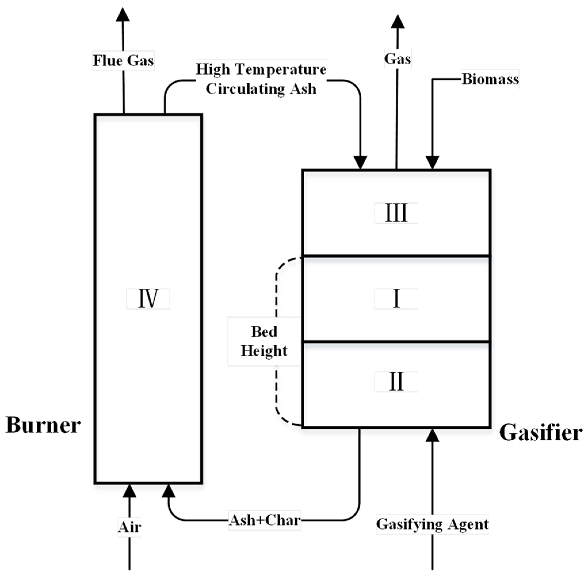
Figure 1. The diagram of reaction zones of a dual fluidized bed system.
Energies 16 04434 g001
Figure 2. (a) Schematic layout of dual fluidized bed system; (b) the physical image.
Energies 16 04434 g002
Figure 3. (a) Differential pressure transmitter image; (b) flow meter image.
Energies 16 04434 g003
Figure 4. The temperature variation curve of the system.
Energies 16 04434 g004
Figure 5. (a) Operating temperature of gasifier; (b) operating temperature of combustion furnace.
Energies 16 04434 g005
Figure 6. Pressure difference variation curve.
Energies 16 04434 g006
Figure 7. (a) Effect of bed material height on gas composition; (b) effect of bed material height on cold gas efficiency and carbon conversion rate.
Energies 16 04434 g007
Figure 8. Curve of the influence of temperature on gas composition.
Energies 16 04434 g008
Figure 9. Effect of gasification temperature on gas calorific value.
Energies 16 04434 g009
Figure 10. Effect of S/B on gas composition.
Energies 16 04434 g010
Figure 11. Effect of Ca/C on gas composition.
Energies 16 04434 g011
Table 1. Temperature measurement points, pressure measurement points, and feeding port positions of the combustion furnace.
TitleSymbolPosition (Air Distribution Plate Distance/mm)
Air chamber temperatureT0−40
Dense phase zone temperatureT1200
Temperature at the boundary of the lean and dense phase zone in the combustion furnaceT2700
Middle part temperatureT31500
Middle part temperatureT42950
Pressure of chamberP0−40
Bottom pressure of combustion furnaceP1200
Middle pressure of combustion furnaceP21500
Top pressure of combustion furnaceP32950
inlet 400
Table 2. Temperature measurement points, pressure measurement points, feeding port and air inlet positions of the gasifier.
TitleSymbolPosition (Air Distribution Plate Distance/mm)
Bottom temperature T8255
Middle temperatureT7800
Top temperature T91600
Bottom temperature P8255
Middle pressureP7800
Top pressureP61600
Bottom inlet 100
Top inlet 1650
Table 3. Ultimate and proximate analysis of the CHR (air-dried basis).
ProjectValueMethodInstrument
Moisture5.45Industrial methods of coal analysisscale (GB1302)
drying oven (102A)
Ash10.14
Volatiles67.34scale (GB1302)
Fixed Carbon17.07muffle (RJM-1.8-10)
Lower Heating Value (LHV) (kJ/kg)Heat Value15,300Method for determination of calorific value of coalCalorimeter (AC-350 USA)
Ultimate Analysis
(wt%)
C42.31Methods for determination of carbon and hydrogen in coalTQ-3 type C and H element analyzer
H6.01
S0.25Method for determination of total sulfur in coalCLS-1 Coulomb sulfur meter
N3.23Method for elemental analysis of coalChemical titrator
O32.61Method for determination of oxygen in coalFlash Smart
Disclaimer/Publisher’s Note: The statements, opinions and data contained in all publications are solely those of the individual author(s) and contributor(s) and not of MDPI and/or the editor(s). MDPI and/or the editor(s) disclaim responsibility for any injury to people or property resulting from any ideas, methods, instructions or products referred to in the content.