Assessment and Commissioning of Electrical Substation Grid Testbed with a Real-Time Simulator and Protective Relays/Power Meters in the Loop
Abstract
1. Introduction
2. Materials and Calculations
2.1. Electrical and Communication Diagram in the Testbed
2.2. Theory and Calculations
2.2.1. Voltage and Current Gains for the RTS
2.2.2. Inverse Time Overcurrent Protection
2.2.3. Current and Voltage Measured Percentage Errors
2.3. Simulation Environment and RT-LAB Project
3. Methodology
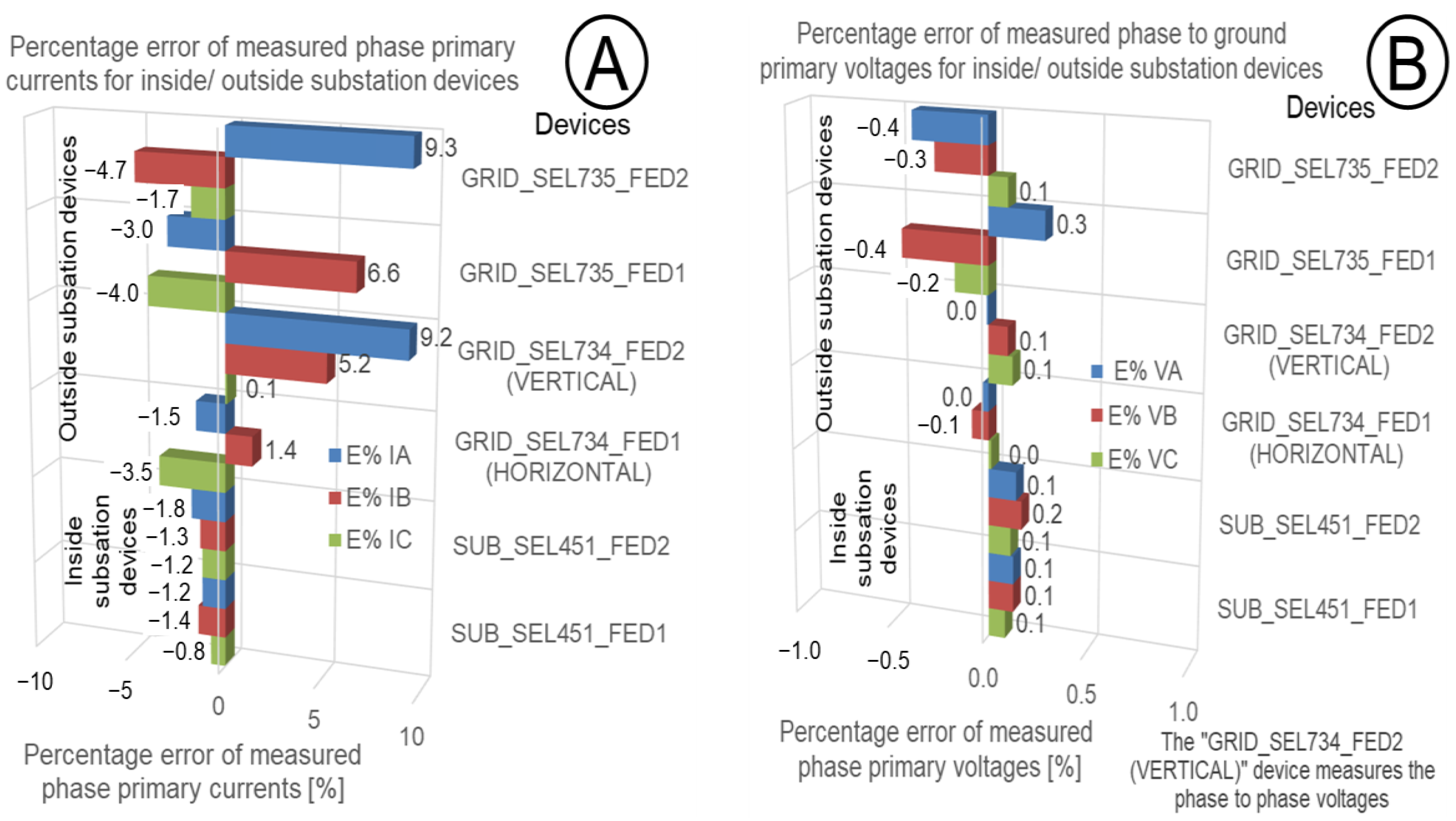
3.1. Commission of Current and Voltage Signals for Power System Applications
3.2. Commissioning of the Phase Voltage Polarity and Balanced Power System
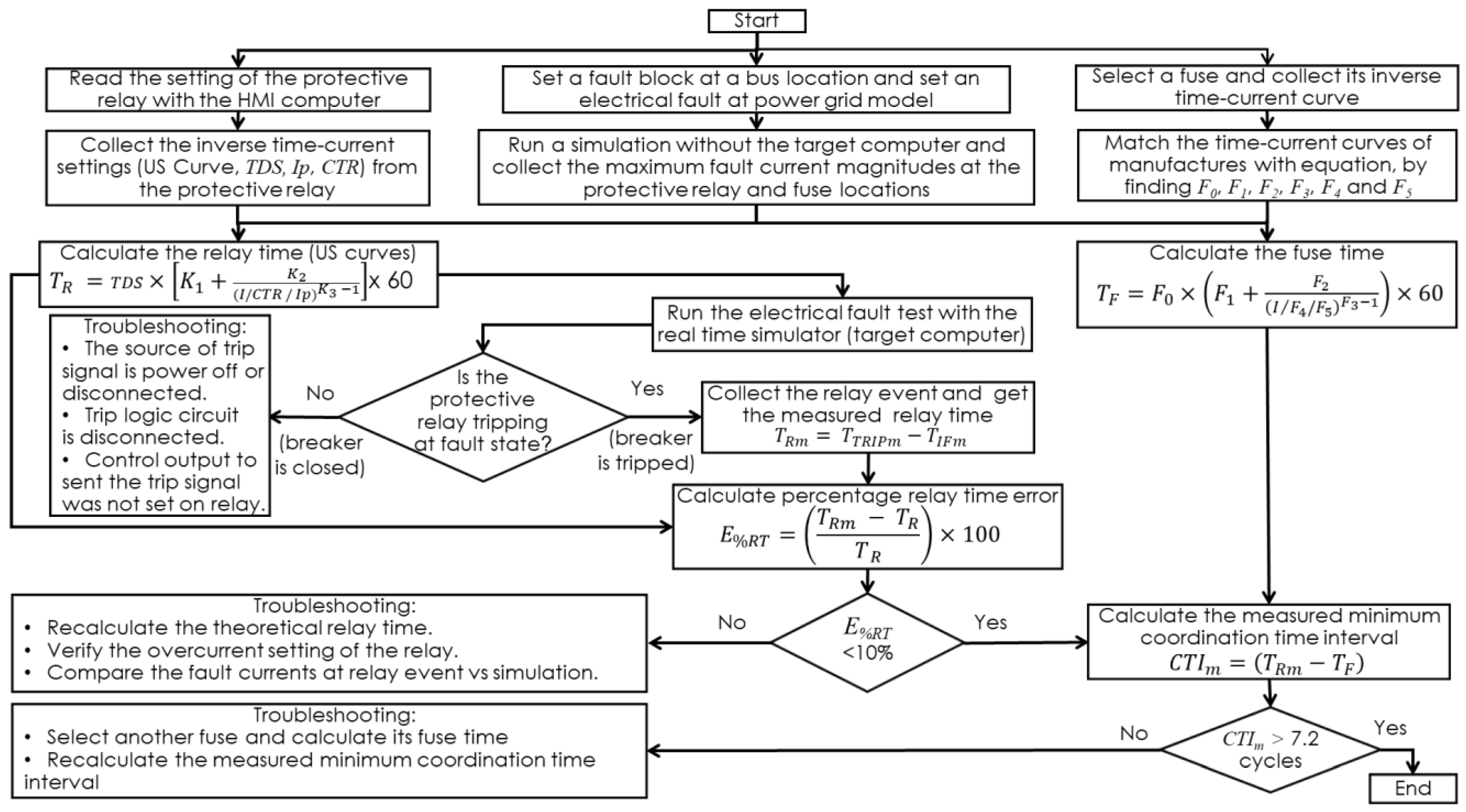
3.3. Commission of the Protective Relay Time, Selectivity Coordination, and Breaker Operation
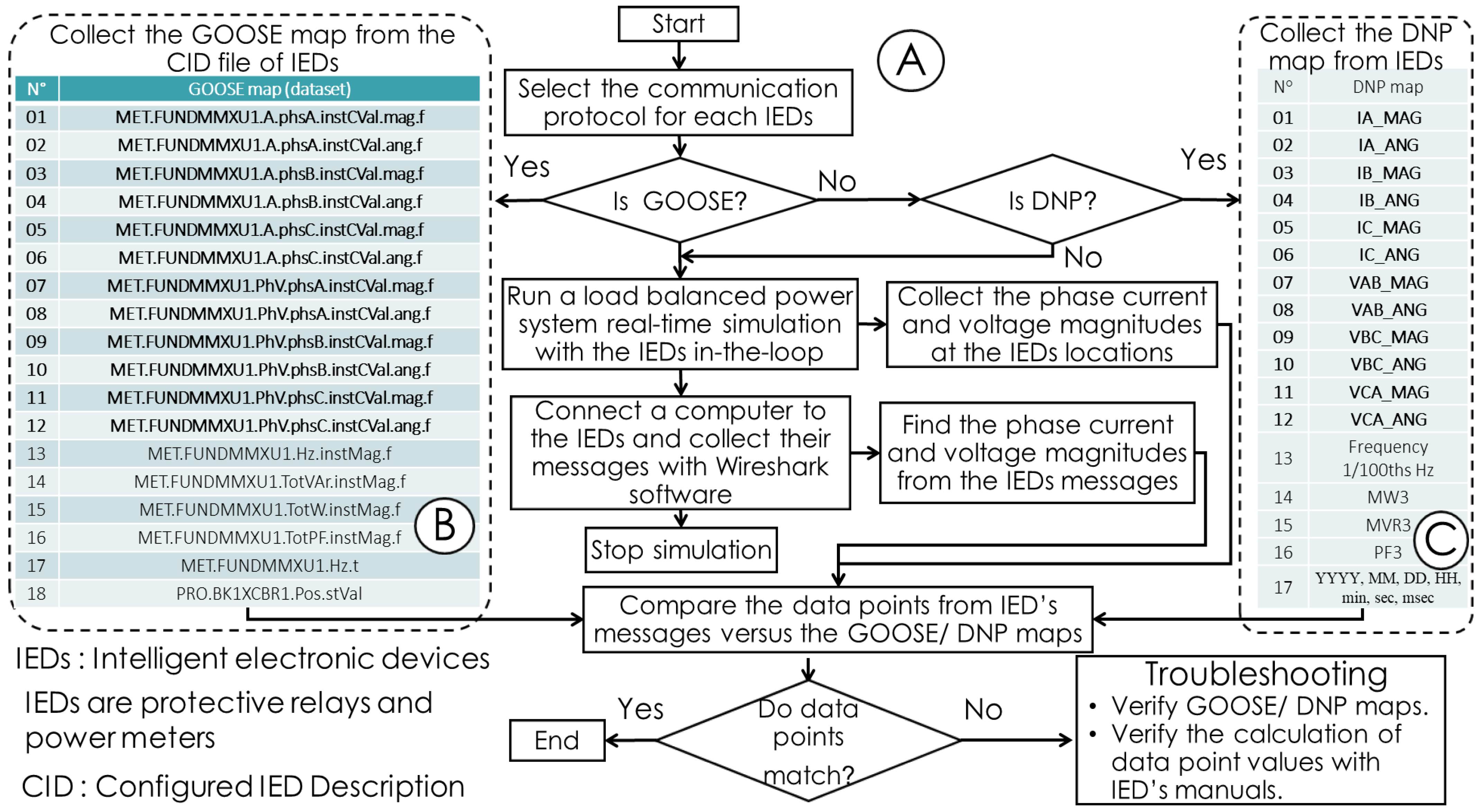
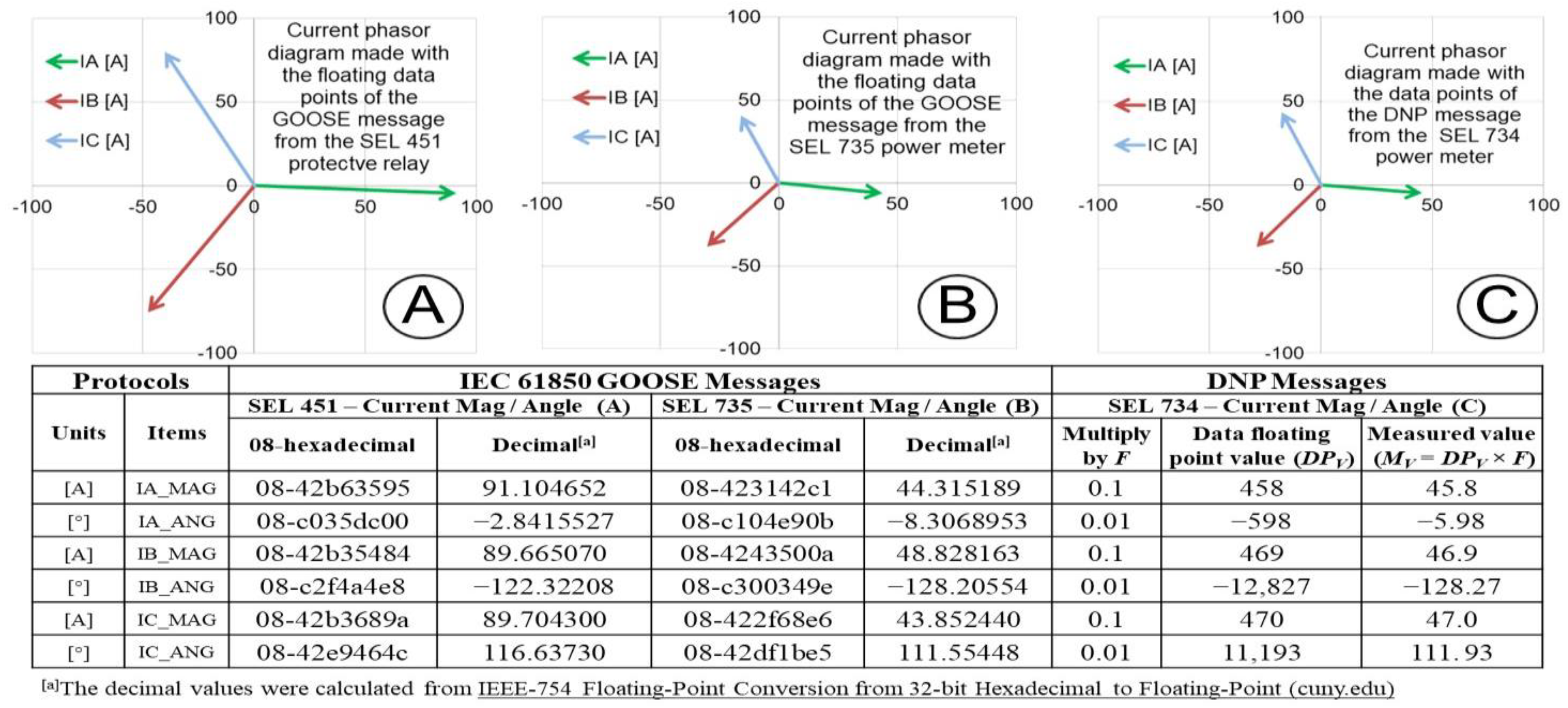
3.4. Commissioning of the Data Points for Protocols and Time Source
3.5. Technical and Economic Aspects of Commissioning a Real Electrical Substation versus an ESGT
4. Results
5. Discussion
- Number of IEDs: the number of power meters and protective relays that can be wired with the real-time simulator will be limited by the number of available analog and digital cards on the system. The actual system can connect a maximum number of teen IEDs in the loop. However, adding extra expansion boxes can increase the number of IEDs in the loop.
- Sampling frequency: protective relays and power meters have a sampling frequency. The sampling frequency of a signal should be at least twice the bandwidth of the signal to avoid aliasing at measuring the analog signals [13]. Therefore, IEDs with high sampling frequencies can measure and consequently assess algorithms for high harmonics scenarios, such as electrical faults and operation of inverter-based systems with DERs [11].
- Low-voltage interface vs. amplifiers: power meters and protective relays should be connected to the low-voltage level interface instead of using current and voltage amplifiers that have low cutoff frequencies. Sometimes, current and voltage scaling factors are not provided by IED’ manufactures, and the low-voltage level interface is not an option. However, the current and voltage scaling factors and unknown pinouts of low-voltage interfaces for IEDs can be obtained by a practical method [35].
- MATLAB/Simulink models: power system models in MATLAB/Simulink are a great tool to use with power systems testbeds in laboratories. However, these power system models are based on a simulation program that has been developed, and they can have some capabilities and limitations [37]. However, the broad use of MATLAB/Simulink have increased, and the power systems model have been continually being improved by students, professors, and researchers.
6. Conclusions
Author Contributions
Funding
Data Availability Statement
Conflicts of Interest
Nomenclature
| Abbreviations | |
| CGG | cyber-grid guard |
| CID | configured IED description |
| CTI | coordination time interval |
| DERs | distributed energy resources |
| DLT | distributed ledger technology |
| DNP | distributed network protocol |
| ESGT | electrical substation grid testbed |
| GOOSE | generic object oriented substation event |
| HIL | hardware in the loop |
| IEDs | intelligent electronic devices |
| ITC | inverse time current |
| LL | line to line |
| LLG | line to line ground |
| RTS | real-time simulator |
| SEL | Schweitzer Engineering Laboratories |
| SLG | single line to ground |
| 3LG | Three lines to ground |
| Symbols | |
| CAF | current amplifier factor (A/V) |
| CGMETER | current gain in the RTS for the power meter |
| CGRELAY | current gain in the RTS for protective relay |
| CSF | current scaling factor of protective relay (A/V) |
| CTR | current transformer ratio |
| CTRMETER | current transformer ratio of the power meter |
| CTRRELAY | current transformer ratio of the protective relay |
| CTI | calculated CTI between backup (relay) and primary (fuse) protective devices (cycles) |
| CTIm | ceasured CTI between backup (relay) and primary (fuse) protective devices (cycles) |
| E% In | Percentage error of the measured phase n currents |
| E%RT | percentage relay time error |
| E% Vn | percentage error for measured phase n voltages F0, F1, F2, F3, F4, and F5: Curve constants for the fuses |
| GADJ n | phase n current or voltage adjusted gains in the RTS for the IEDs |
| GCALC n | phase n current or voltage calculated gains in the RTS for the IED |
| I | primary input current (A) |
| In HMI | phase n currents collected from the IEDs’ HMI (A) |
| In RTS | phase n currents collected from the RTS (A) |
| IP | relay current pickup setting (A) |
| K1, K2, and K3 | curve constants for the U3 Very ITC curves |
| M | multiple of pickup current |
| M RTS n | phase n measured current (A), or voltage (V) from the RTS |
| M HMI n | phase n measured current (A), or voltage (V) from the HMI’s IEDs |
| n | phase A, B, or C |
| PTRMETER | potential transformer ratio of the power meter |
| PTRRELAY | potential transformer ratio of the protective relay |
| TDS | time dial setting (s) |
| TF | calculated clearing time of fuse (cycles) |
| TIFm | measured initial fault state time (cycles) |
| TR | calculated time of the relay (cycles) |
| TRm | measured relay time (cycles) |
| TTRIPm | measured relay trip time (cycles) |
| VAF | voltage amplifier factor (V/V) |
| VGMETER | voltage gain in the RTS for the power meter |
| VGRELAY | voltage gain in the RTS for the protective relay |
| Vn HMI | phase n voltages collected from the IEDs’ HMI (V) |
| Vn RTS | phase n voltages collected from the RTS (V) |
| VSF | voltage scaling factor of the protective relay (V/V) |
References
- Atwa, O.S.E. Practical Power System and Protective Relays Commissioning; Academic Press: Cambridge, MA, USA, 2019. [Google Scholar]
- C37.233-2009; IEEE Guide for Power System Protection Testing. IEEE Std.: Piscataway, NJ, USA, 2009.
- Understanding the Commissioning Process for Utility Systems. ComRent Load Bank Solutions. 2017. Available online: https://www.tdworld.com/resources/white-papers/whitepaper/20969596/understanding-the-commissioning-process-for-utility-systems (accessed on 17 May 2023).
- 1547.1-2020; IEEE Standard Conformance Test Procedures for Equipment Interconnecting Distributed Energy Resources with Electric Power Systems and Associated Interfaces. IEEE Std.: Piscataway, NJ, USA, 2020.
- Jing, S.; Huang, Q.; Wu, J.; Zhen, W. A Novel Whole-View Test Approach for Onsite Commissioning in Smart Substation. IEEE Trans. Power Deliv. 2013, 28, 1715–1722. [Google Scholar] [CrossRef]
- Johansen, P. Substation Monitoring and Control, Part 1: Capacitive Voltage Measurement. Substation Control, Jomitek. Available online: http://jomitek.dk/downloads/Substation%20monitoring%20and%20control.pdf (accessed on 17 May 2023).
- Donolo, M.A.; Centeno, V.A. Accuracy Limits for Synchro Phasor Measurements and the IEEE Standard. IEEE Trans. Power Deliv. 2008, 23, 504–505. [Google Scholar] [CrossRef]
- C37.118.2-2011; IEEE Standard for Synchro phasor Data Transfer for Power Systems. IEEE Std.: Piscataway, NJ, USA, 2011.
- Lu, J.; Zhao, X.; Yamada, S. Harmonic Balance Finite Element Method: Applications in Nonlinear Electromagnetics and Power Systems; IEEE Press: Piscataway, NJ, USA; John Wiley & Sons Singapore Pte Ltd: Hoboken, NJ, USA, 2016. [Google Scholar]
- Chicco, G.; Schlabbach, J.; Spertino, F. Experimental assessment of the waveform distortion in grid-connected photovoltaic installations. Sol. Energy 2009, 83, 1026–1039. [Google Scholar] [CrossRef]
- Piesciorovsky, E.C.; Karnowski, T. Variable frequency response testbed to validate protective relays up to 20 kHz. Electr. Power Syst. Res. 2021, 194, 107071. [Google Scholar] [CrossRef]
- Das, S. Sub-Nyquist rate ADC sampling in digital relays and PMUs: Advantages and challenges. In Proceedings of the 6th IEEE International Conference on Power Systems, New Delhi, India, 4–6 March 2016; pp. 1–6. [Google Scholar]
- 242-2001; IEEE Recommended Practice for Protection and Coordination of Industrial and Commercial Power Systems. IEEE Std.: Piscataway, NJ, USA, 2001.
- F6000 Family of Power System Simulators User Guide, Doble Engineering Company, 2001, 72A-1589 Rev. C. Available online: http://userequip.com/files/specs/5394/F6000%20User%20Guide.pdf (accessed on 17 May 2023).
- Faruque, M.O.; Strasser, T.; Lauss, G.; Jalili-Marandi, V.; Forsyth, P.; Dufour, C.; Dinavahi, V.; Monti, A.; Kotsampopoulos, P.; Martinez, J.A.; et al. Real-Time Simulation Technologies for Power Systems Design, Testing, and Analysis. IEEE Power Energy Technol. Syst. J. 2015, 2, 63–73. [Google Scholar] [CrossRef]
- Menghal, P.M.; Laxmi, A.J. Real time simulation: Recent progress & challenges. In Proceedings of the International Conference on Power, Signals, Controls and Computation (EPSCICON), Thrissur, India, 3–6 January 2012; pp. 1–6. [Google Scholar]
- Dufour, C.; Mahseredjian, J.; Bélanger, J. A combined state-space nodal method for the simulation of power system transients. IEEE Trans. Power Deliv. 2011, 26, 928–935. [Google Scholar] [CrossRef]
- Pak, L.-F.; Faruque, M.; Nie, X.; Dinavahi, V. A Versatile Cluster-Based Real-Time Digital Simulator for Power Engineering Research. IEEE Trans. Power Syst. 2006, 21, 455–465. [Google Scholar] [CrossRef]
- Dufour, C.; Bélanger, J. A PC-based real-time parallel simulator of electric systems and drives. In Proceedings of the Parallel Computing in Electrical Engineering (PARELEC), Dresden, Germany, 7–10 September 2004; pp. 105–113. [Google Scholar]
- Faruque, M.O.; Dinavahi, V. An advanced PC-cluster based real time simulator for power electronics and drives. In Proceedings of the IEEE international symposium on industrial electronics (ISIE), Montreal, QC, Canada, 9–13 July 2006; pp. 2579–2584. [Google Scholar]
- Hahn, A.; Ashok, A.; Sridhar, S.; Govindarasu, M. Cyber-Physical Security Testbeds: Architecture, Application, and Evaluation for Smart Grid. IEEE Trans. Smart Grid 2013, 4, 847–855. [Google Scholar] [CrossRef]
- Oyewumi, I.A.; Jillepalli, A.A.; Richardson, P.; Ashrafuzzaman, M.; Johnson, B.K.; Chakhchoukh, Y.; Haney, M.A.; Sheldon, F.T.; de Leon, D.C. ISAAC: The Idaho CPS Smart Grid Cybersecurity Testbed. In Proceedings of the IEEE Texas Power and Energy Conference, College Station, TX, USA, 7–8 February 2019; pp. 1–6. [Google Scholar]
- Yang, Y.; Jiang, H.T.; McLaughlin, K.; Gao, L.; Yuan, Y.; Huang, W.; Sezer, S. Cybersecurity Test-Bed for IEC 61850 based Smart Substations. In Proceedings of the IEEE Power & Energy Society General Meeting, Denver, CO, USA, 26–30 July 2015; pp. 1–5. [Google Scholar]
- Jurišić, G.; Havelka, J.; Capuder, T.; Sučić, S. Laboratory Test Bed for Analyzing Fault-Detection Reaction Times of Protection Relays in Different Substation Topologies. Energies 2018, 11, 2482. [Google Scholar] [CrossRef][Green Version]
- Edvard, C. Six Common Bus Configurations in Substations Up to 354 Kv. Electrical Engineering Portal. 18 March 2019. Available online: https://electrical-engineering-portal.com/bus-configurations-substations-345-kv (accessed on 17 May 2023).
- Piesciorovsky, E.; Hink, R.B.; Werth, A.; Hahn, G.; Richards, J.; Lee, A.; Polsky, Y. Assessment of the Electrical Substation Grid Testbed with Inside/Outside Devices and Distributed Ledger Technology; ORNL/TM-2022/1840; Oak Ridge National Laboratory: Oak Ridge, TN, USA, 2022. [Google Scholar]
- SEL-451-5 Protection, Automation, and Bay Control System and SEL-400 Series Relays Instruction Manual, Schweitzer Engineering Laboratories Inc. Available online: https://selinc.com/products/451/docs/ (accessed on 17 May 2023).
- Piesciorovsky, E.C.; Schulz, N.N. Comparison of non-real-time and real-time simulators with relays in-the-loop for adaptive overcurrent protection. Electr. Power Syst. Res. 2017, 143, 657–668. [Google Scholar] [CrossRef]
- SEL-735 Power Quality and Revenue Meter Instruction Manual, Schweitzer Engineering Laboratories Inc. Available online: https://selinc.com/products/735/docs/ (accessed on 17 May 2023).
- SEL-734 Advanced Metering System Instruction Manual, Schweitzer Engineering Laboratories Inc. Available online: https://selinc.com/products/734/docs/ (accessed on 17 May 2023).
- OP8120 Modular Signal Conditioning Chassis User Manual, OPAL RT Technologies. Available online: https://www.opal-rt.com/resource-center/document/?resource=L00161_0342 (accessed on 17 May 2023).
- TCC Number 170-6-2 (Excel), Positrol Fuse Links, S&C “T” Speed, Total Clearing. Available online: https://www.sandc.com/en/contact-us/time-current-characteristic-curves/ (accessed on 17 May 2023).
- Bowen, J. Substation commissioning and turnover planning. IEEE Ind. Appl. Mag. 2000, 6, 8–22. [Google Scholar] [CrossRef]
- Ruiz, D.; Stephens, R.; Gaynor, P.; Wilson, J. Design, Startup, and Commissioning of a 230 kV–13.8 kV Substation. In Proceedings of the 2006 Record of Conference Papers—IEEE Industry Applications Society 53rd Annual Petroleum and Chemical Industry Conference, Philadelphia, PA, USA, 11–15 September 2006; pp. 1–9. [Google Scholar]
- Piesciorovsky, E.C.; Smith, T.; Mukherjee, S.K.; Marshall, M.W. A generic method for interfacing IEDs using low voltage interfaces to real-time simulators with hardware in the loop. Electr. Power Syst. Res. 2021, 199, 107431. [Google Scholar] [CrossRef]
- 7228 Operator’s Manual, Single-Channel Industrial Amplifier for Demanding, High-Power Systems, AE TECHRON, 97-8004188_08-31-2020. Available online: https://aetechron.com/pdf/7228_OperatorManual.pdf (accessed on 17 May 2023).
- Martins, L.S.; Costa, D.; Martins, J.F.; Pires, V.F. Modeling for computer simulation as a tool for the teaching of transient power systems. In Proceedings of the 2009 International Conference on Power Engineering, Energy and Electrical Drives, Lisbon, Portugal, 18–20 March 2009; pp. 629–634. [Google Scholar]
- El Kalam, A.A.; Outchakoucht, A.; Es-Samaali, H. Emergence-based access control: New approach to secure the Internet of Things. In Proceedings of the 1st International Conference on Digital Tools & Uses Congress, Paris, France, 3–5 October 2018; pp. 1–11. [Google Scholar]
- Fragkos, G.; Johnson, J.; Tsiropoulou, E.E. Dynamic Role-Based Access Control Policy for Smart Grid Applications: An Offline Deep Reinforcement Learning Approach. IEEE Trans. Human-Machine Syst. 2022, 52, 761–773. [Google Scholar] [CrossRef]
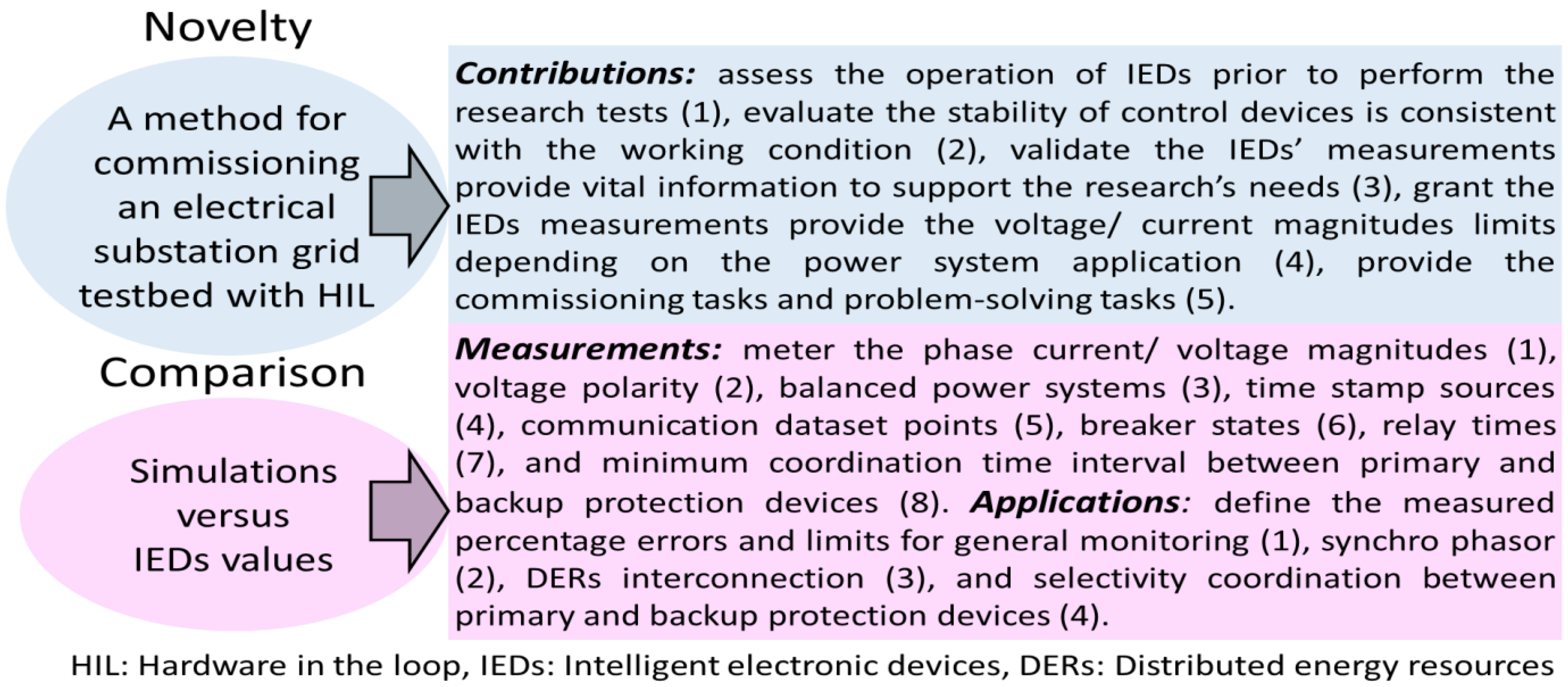


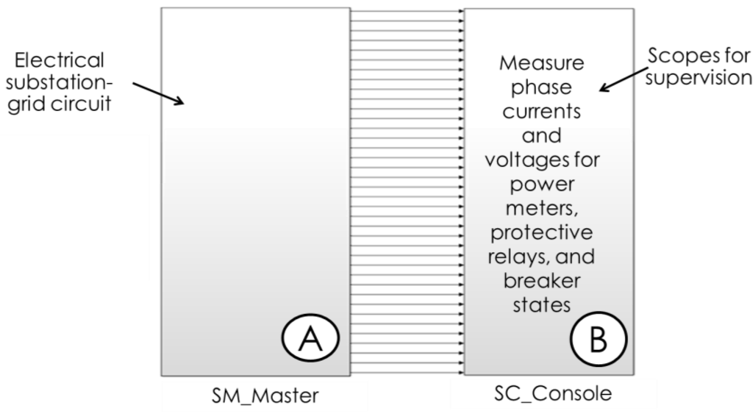
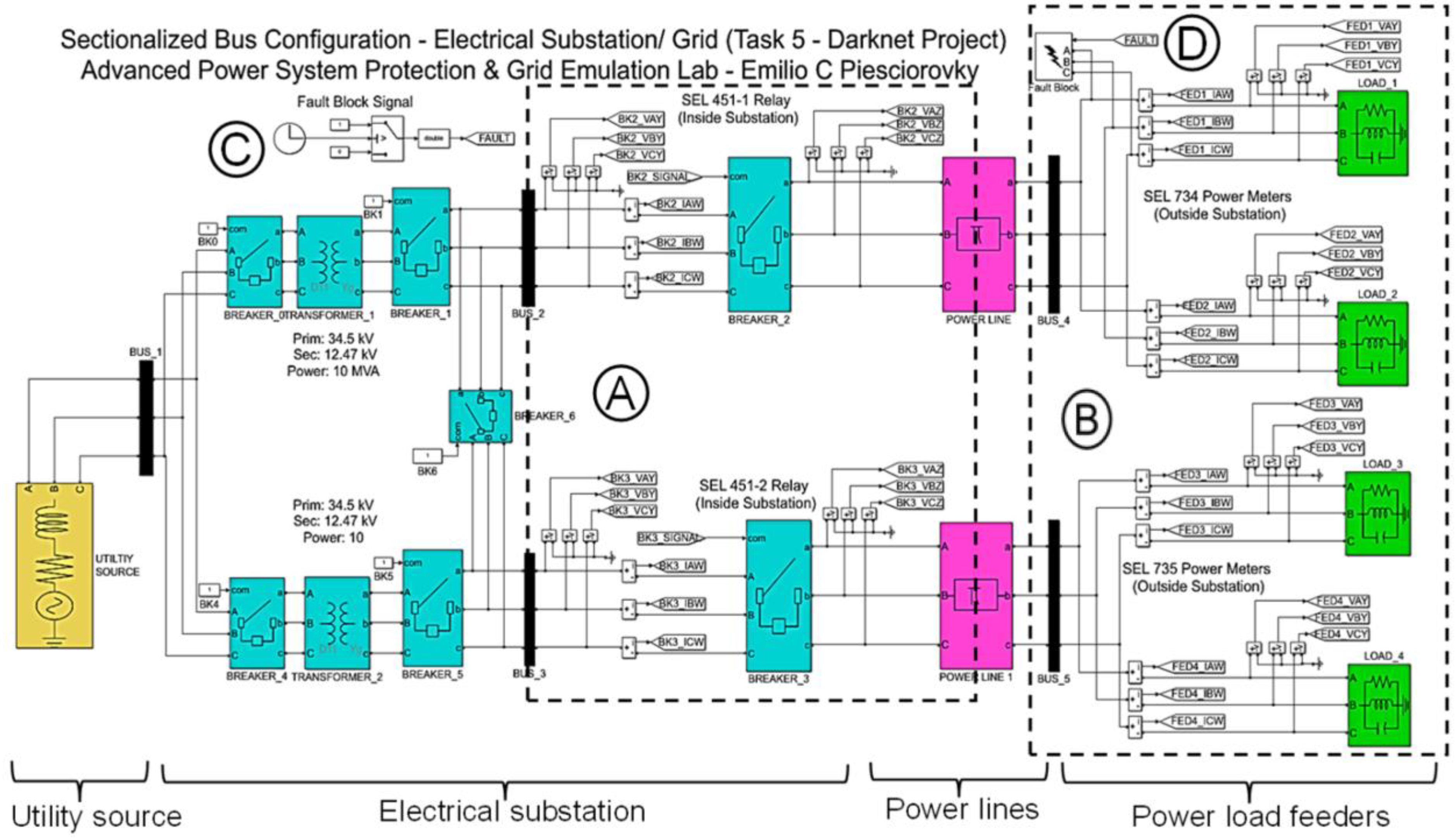

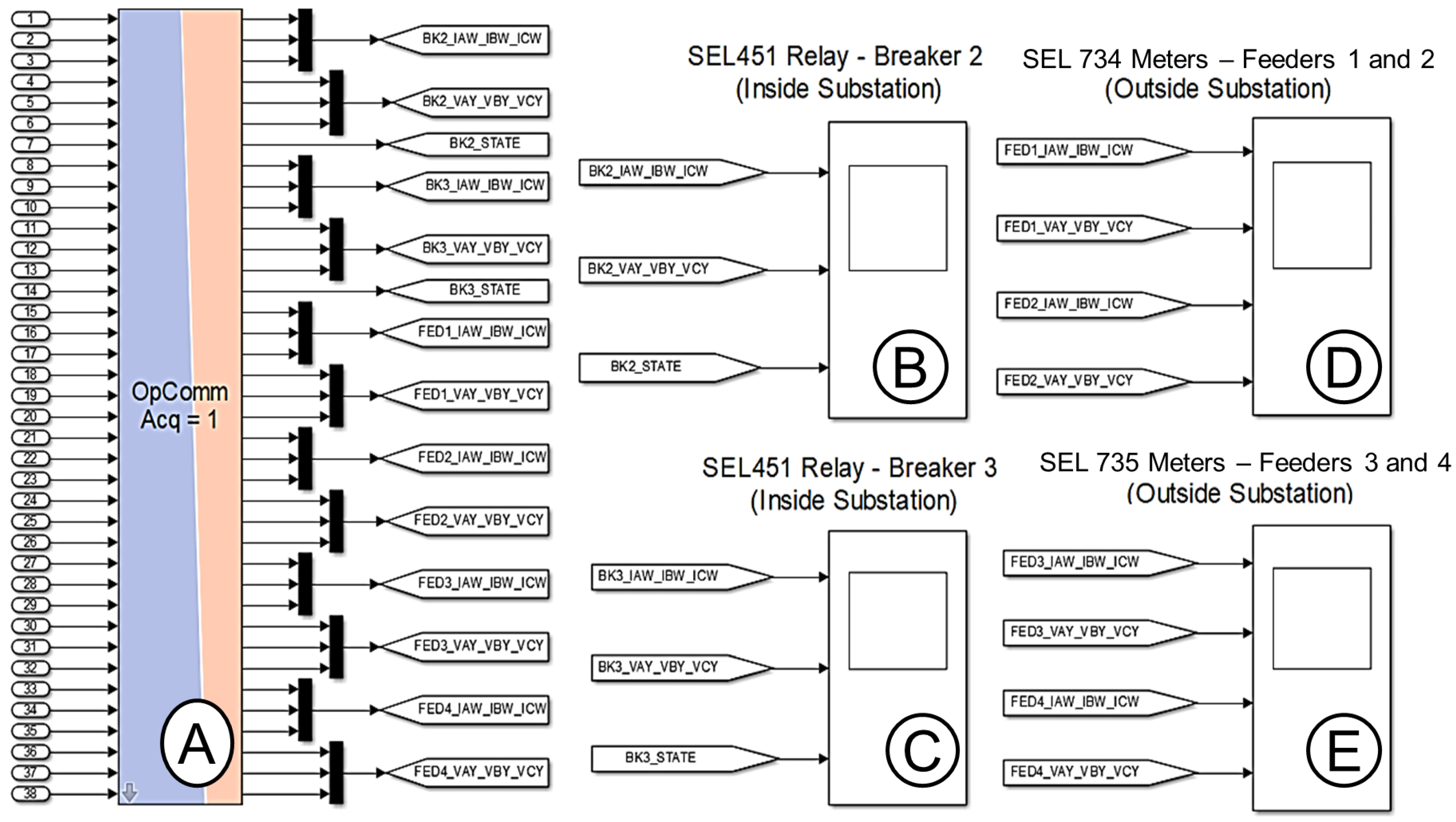







| Type of Simulation | Measurement Applications at Electrical Substations and Power Grids | Percentage Error and Minimum CTI Limits | |
|---|---|---|---|
| Power flow analysis | Voltage, current, frequency, real and reactive power, and so on | General monitoring [6] | 5% |
| Synchro phasor [7,8] | 1% * | ||
| Interconnecting DERs [4] | 1% | ||
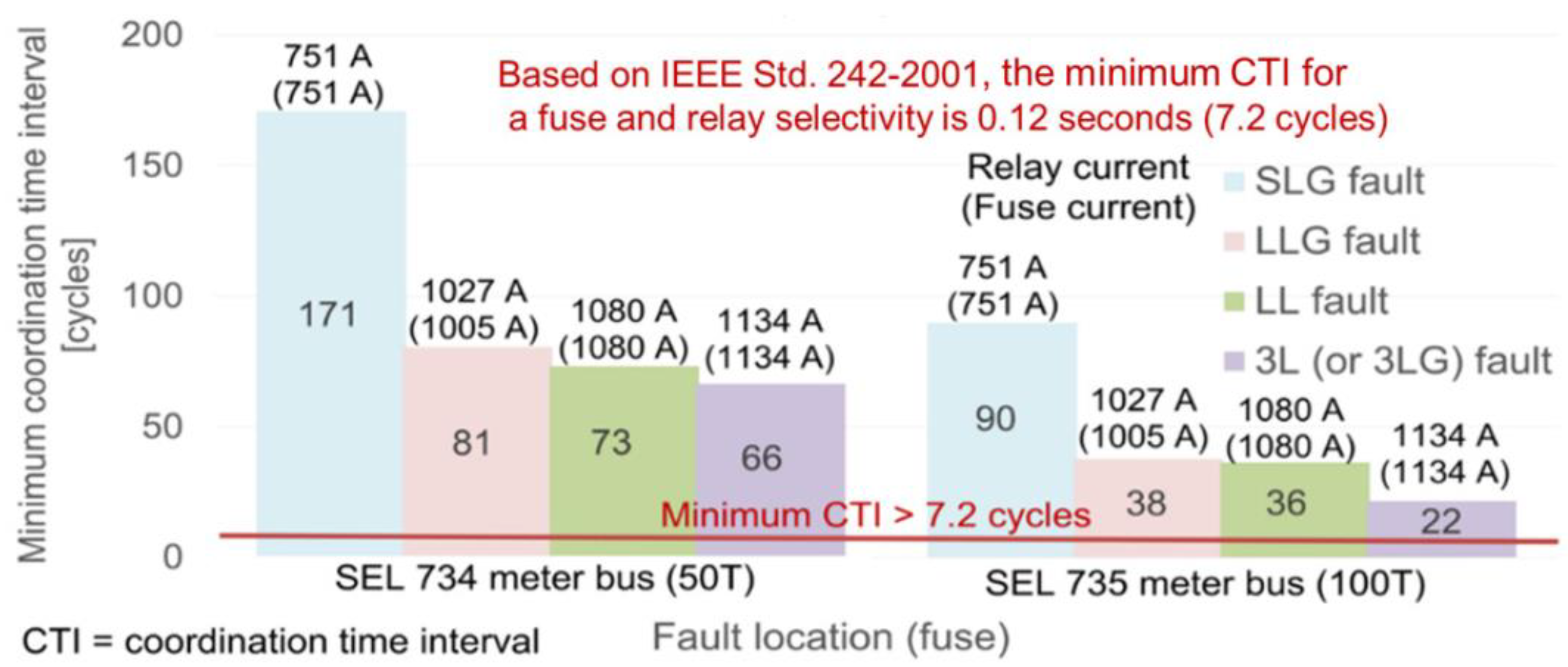
| Electrical fault analysis (transient event states) | Selectivity between primary and backup overcurrent protection devices | Primary fuse and backup relay [13] | 7.2 cycles ** |
| Primary and backup relays [13] | 12.2 cycles ** | ||
| Software | Solver (Powergui Block) | |||
|---|---|---|---|---|
| Real-Time Simulator | Power System Model | Simulation Type | Sample Time [μs] | Frequency [Hz] |
| RT-LAB | MATLAB/Simulink | Discrete | 50 | 60 |
| Power Flow Simulations | Areas | Commissioning Tasks | Problem-Solving Tasks |
| Analog signals | Compare the measured current and voltage magnitudes of the HMI’s relays and meters versus the simulations. | Adjust current/voltage gains. Adjust setting of CTs or PTs at relays and/or meters. | |
| Compare the measured phase sequence of voltages and currents of the HMI’s relays and meters versus simulations. | Connect the positive, negative, and/or ground wires of analog signals for the meters, relays, amplifiers, and RTS. | ||
| Observe the measured sinusoidal shape of currents and voltages from meter displays. | Adjust current/voltage gains. | ||
| Breakers | Close and trip the breakers from the HMI or push buttons of the protective relays. | Measure the trip–close signal voltage levels. Revise the trip–close logic circuit. | |
| Time source | Compare the measured time stamps of protective relays and meters at device displays versus the digital clock. | Connect the correct IRIG-B cable to the meters and protective relays. | |
| Messages | Compare the measured Wireshark data set points for the IEC 61850 and DNP messages versus the data set maps set on the IEDs. | Revise and set the downloaded dataset maps of meters and protective relays. | |
| Electrical Fault Simulations | Breakers | Observe that the breaker was tripped by the protective relay at the electrical fault tests. | Revise the logic circuit, voltage source, and/or control output’s relay setting for the trip signals. |
| Overcurrent relay settings | Collect the relay event for the electrical fault test to compare the measured and calculated relay times. | Revise the overcurrent settings of the protective relays. Revise the calculated relay time with the inverse current–time curves. | |
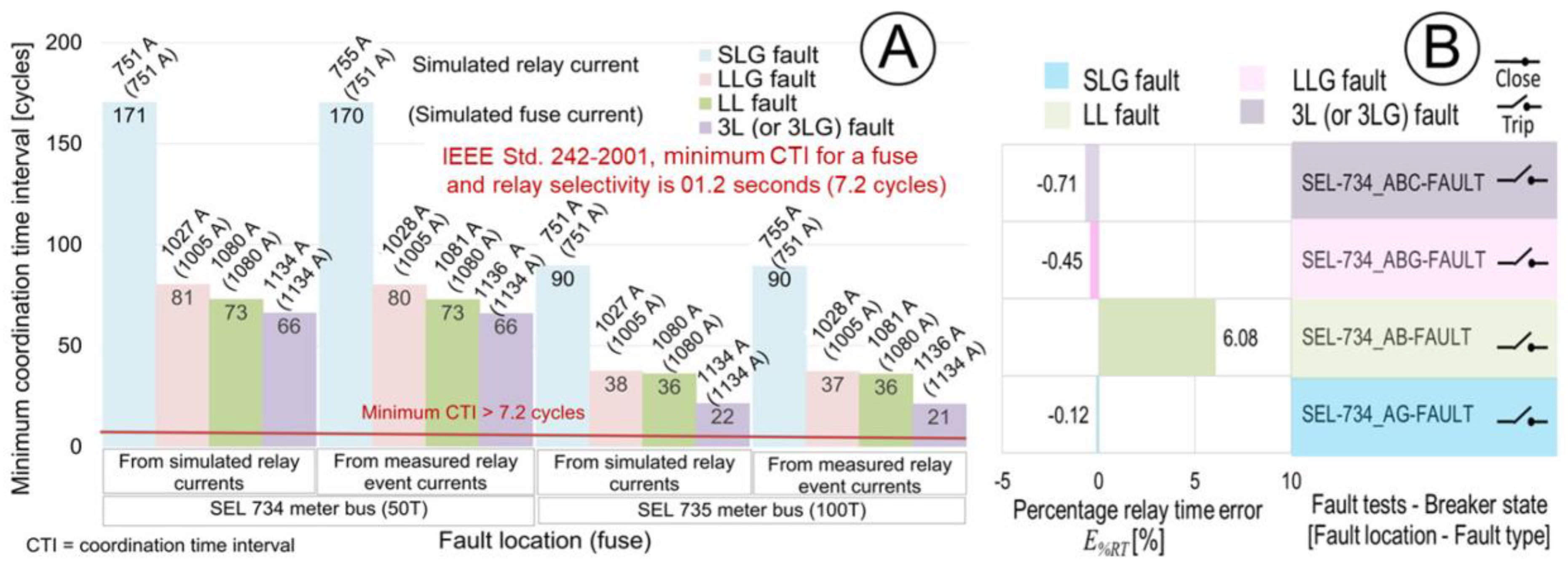
| Selectivity coordination | Verify that the primary protective devices trip faster than the backup protective devices for maximum fault current, minimum CTI > 7.2 cycles (relay-fuse), and minimum CTI > 12 cycles (relay-relay). | Recalculate the theoretical relay time. Confirm the overcurrent settings of the protective relays. Compare the fault currents at the relay event versus simulation. |
Disclaimer/Publisher’s Note: The statements, opinions and data contained in all publications are solely those of the individual author(s) and contributor(s) and not of MDPI and/or the editor(s). MDPI and/or the editor(s) disclaim responsibility for any injury to people or property resulting from any ideas, methods, instructions or products referred to in the content. |
© 2023 by the authors. Licensee MDPI, Basel, Switzerland. This article is an open access article distributed under the terms and conditions of the Creative Commons Attribution (CC BY) license (https://creativecommons.org/licenses/by/4.0/).
Share and Cite
Piesciorovsky, E.C.; Borges Hink, R.; Werth, A.; Hahn, G.; Lee, A.; Polsky, Y. Assessment and Commissioning of Electrical Substation Grid Testbed with a Real-Time Simulator and Protective Relays/Power Meters in the Loop. Energies 2023, 16, 4407. https://doi.org/10.3390/en16114407
Piesciorovsky EC, Borges Hink R, Werth A, Hahn G, Lee A, Polsky Y. Assessment and Commissioning of Electrical Substation Grid Testbed with a Real-Time Simulator and Protective Relays/Power Meters in the Loop. Energies. 2023; 16(11):4407. https://doi.org/10.3390/en16114407
Chicago/Turabian StylePiesciorovsky, Emilio C., Raymond Borges Hink, Aaron Werth, Gary Hahn, Annabelle Lee, and Yarom Polsky. 2023. "Assessment and Commissioning of Electrical Substation Grid Testbed with a Real-Time Simulator and Protective Relays/Power Meters in the Loop" Energies 16, no. 11: 4407. https://doi.org/10.3390/en16114407
APA StylePiesciorovsky, E. C., Borges Hink, R., Werth, A., Hahn, G., Lee, A., & Polsky, Y. (2023). Assessment and Commissioning of Electrical Substation Grid Testbed with a Real-Time Simulator and Protective Relays/Power Meters in the Loop. Energies, 16(11), 4407. https://doi.org/10.3390/en16114407


