Article

Hybrid Driving Training and Particle Swarm Optimization Algorithm-Based Optimal Control for Performance Improvement of Microgrids

1
The Higher Institute for Engineering and Technology Fifth Settlement, Cairo 11823, Egypt
2
Electrical Power & Machines Department, Faculty of Engineering, Ain Shams University, Cairo 11517, Egypt
3
Faculty of Engineering & Technology, Future University in Egypt, Cairo 11835, Egypt
4
Electrical Engineering Department, College of Engineering, King Saud University, Riyadh 11421, Saudi Arabia
5
School of Electrical and Electronic Engineering, Huazhong University of Science and Technology, Wuhan 430074, China
*
Author to whom correspondence should be addressed.
Energies 2023, 16(11), 4355; https://doi.org/10.3390/en16114355
Submission received: 23 April 2023 / Revised: 19 May 2023 / Accepted: 25 May 2023 / Published: 26 May 2023
(This article belongs to the Special Issue Intelligent Decentralized Energy Management in Microgrids II)

Abstract

:
This paper discusses the importance of microgrids in power systems and introduces a new method for enhancing their performance by improving the transient voltage response in the face of disturbances. The method involves using a hybrid optimization approach that combines driving training-based and particle swarm optimization techniques (HDTPS). This hybrid approach is used to fine-tune the system’s cascaded control scheme parameters, based on proportional–integral–accelerator (PIA) and proportional–integral controllers. The optimization problem is formulated using a central composite response surface methodology (CCRSM) to create an objective function. To validate the suggested control methodology, PSCAD/EMTDC software is used to carry out the simulations. The simulations explore various scenarios wherein the microgrid is transformed into an islanded system and is subjected to various types of faults and load changes. A comparison was made between the two proposed optimized controllers. The simulation results demonstrate the effectiveness of using a PIA-optimized controller; it improved the microgrid performance and greatly enhanced the voltage profile. In addition, the two controllers’ gains were optimized using only PSO to ensure that the outcomes of the HDTPS model demonstrated the same results. Finally, a comparison was made between the two optimization techniques (HDTPS and PSO); the results show a better impact when using the HDTPS model for controller optimization.

1. Introduction

Nowadays, microgrids comprising distributed energy generation (DEG), fed by sustainable energy resources, play an important role in power systems. The microgrids’ main role is to address the increasing growth of energy demand due to the depletion of conventional power sources; they are used to overcome the environmental effects of fossil fuel usage, such as by decreasing the greenhouse effect. Moreover, the DEG enhances the voltage profile and reduces power losses. However, many challenges, such as dynamic stability and robustness, face the expansion of microgrid utilization due to the distributed energy resources connected to it [1]. There are two modes of operation of the microgrid: the grid mode and the autonomous mode. The grid mode occurs when the DEG is connected to the main network through a point of common coupling (PCC). In this mode, the voltage and frequency of the DEGs are the same as those of the network, and each DEG in the microgrid controls its real and imaginary power components, utilizing the d-q current control technique [2,3]. Conversely, in the autonomous mode, the controllers of the microgrid regulate the voltage and frequency to maintain a balance between supply and demand. The control strategies required in the autonomous mode are complex, to ensure operational reliability and satisfactory performance under various operational conditions.
Several techniques have been proposed in the literature for controlling DEG systems while in an autonomous operation mode. Current control techniques, such as droop characteristics, are used for multiple DEG units [4,5]. A novel perspective on the various dynamic responses of the two basic microgrid controls, single-and multi-loop droop control, is demonstrated by the authors of [6]. In [7], a droop-controlled system with a static compensator has been designed to enhance microgrid power quality. V/f controllers can be utilized in the DEG autonomous mode, as demonstrated by the authors of [8]. Nowadays, the implementation of artificial intelligence techniques to improve the control and operation of microgrids is often utilized [9,10]. In [11], a robust control methodology for power factor correction for the DEG, using a combination of real and reactive power component controllers, is presented. Although the use of PI and PIA controllers in power systems is widespread, due to their stability, they are also sensitive to variations in system parameters and nonlinearity. To address these issues, several techniques have been employed for fine-tuning the controllers or designing them for various power system applications. For instance, in [12], genetic and particle swarm optimization (PSO) algorithms are utilized to regulate the frequency of a microgrid and optimize the static compensator operation. Moreover, the authors of [13] propose the use of the chaotic crow search algorithm for microgrid performance enhancement. The adaptive Widrow–Hoff technique has been applied to enhance microgrid performance by adapting the PI controller constants online [14]. A hybrid optimization technique, including the PSO and cuttlefish algorithms, is suggested in [15] for finding the PIA controller’s optimal gain values. In [16], the authors investigate the application of fractional-order PID and proportional integrator derivative algorithms in hybrid nuclear and sustainable energy systems. In [17], an artificial bee colony optimization algorithm is used to adjust the controller parameters to meet the system performance criteria. In addition, a secondary load frequency control based on fractional order PID is proposed; the fractional PID controller gain values are tuned using cohort intelligence-based optimization. The performance of the PI-tuned fractional order PID regulator is compared to that of the conventional PID controller, which is tuned using the genetic and PSO algorithms for various scenarios on single- and dual-control-area microgrid systems. Furthermore, in [18], the authors study the load frequency control for two microgrids connected by a tie-line. Various optimization algorithms, including the moth flame, firefly, and ant lion algorithms, are utilized to design controllers because of their dynamic response. In [19], a hierarchical droop-free control scheme is proposed for an inverter-based AC microgrid that can be adapted for use in other control schemes. This methodology applies droop-controlled microgrids and sharing power mismatches concurrently, for regulating the frequency and voltage. Moreover, the authors of [20] present an enhanced PI distributed control scheme to regulate the frequency and voltage of a droop-controlled microgrid and share the power mismatch among distributed generation units that periodically share information with their neighboring units via a communication network. In [21], a wind-side converter is used with a PI controller to generate PWM pulses, while the PV-side converter is controlled by a grey wolf-optimized PI controller, which has a better transient reaction. The battery is connected to a bidirectional converter and artificial neural networks regulate the duty ratio for the converter. Through a three-phase inverter that is managed using DQ theory, the generated electricity is connected to the grid. Another study [22] addresses load frequency control in a multi-microgrid consisting of two microgrids connected by a tie-line, using a mathematical model based on the use of green energy sources with multiple load perturbations. In [23], the authors propose a new hybrid optimization approach using Garra Rufa fish optimization and isolation forest soft computing to optimize controller parameters in an isolated test microgrid. A novel supervisory control approach based on model predictive control and using a stochastic optimization model, with an objective function comprising combined cost-based and system-based components, is presented in [24]. The goal of the authors of [25] is to enhance the stability of the voltage and overall power quality in AC-DC microgrid systems. To achieve this objective, intelligent fuzzy controllers such as fuzzy-PI and fuzzy-PID current controllers will be utilized, along with the inclusion of a distribution static synchronous compensator to enable the network-based control of multiple DEGs, which provides a reliable link between the utility system and the microgrid. The integration of a small-scale power grid, consisting of several renewable energy plants, with the main power grid is achieved through a supervisory control approach. The small-scale grid is operated using a micro-grid concept, which allows for the coordinated control of renewable energy plants [26]. The methodology and control mechanisms suggested in [27,28] align various power systems using the current-voltage phase angle without requiring access to a common connection point, even if there are issues with voltage quality. If there are disruptions to the grid voltage, the instantaneous phase angle is remotely estimated and then transmitted with varying accuracy, which is influenced by the voltage disturbances and the synchronization algorithm’s data transmission rate. The studies highlight how voltage disturbances affect the remote synchronization approach and the synchronized power converter’s output current shape in a microgrid. In order to identify the neighborhood’s best MG to assist other systems in times of need, the authors of [29,30] adopted particle swarm optimization and heuristic-based optimization approaches. It is proposed that multiple MGs can be coordinated by the control scheme suggested in [31] by optimizing their use of renewable energy. Nevertheless, because all these control methods rely on communication, the system’s dependability is still compromised. In [5,32,33,34], the authors suggest a method for managing distributed energy coordination based on droop control. The limitation of this control is in the ongoing power exchange between the two MGs, which causes extra power loss. To deal with this problem, an updated control approach has been put forth in other studies [35,36,37,38]. In this approach, the power flow between two MGs only occurs when they are operating at a certain threshold.
It is crucial to remember that each optimization technique has its own advantages and disadvantages, as previously mentioned. All optimization issues cannot be successfully solved by a single optimization procedure. For a more accurate and reliable solution, recent research has tended to present hybrid optimization methodologies. The authors of this paper were inspired by significant advancements in evolutionary computational techniques to develop a new optimization method for improving microgrid performance through the design of a PIA controller. This paper’s principal contribution to the literature is to propose a new application of the HDTPS for enhancing the performance of inverter-based DEG systems, specifically using a vector-cascaded control technique. The proposed HDTPS optimization technique is used to fine-tune the PIA and PI controllers’ parameters. The CCRSM defines the optimization problem’s objective function, which is the maximization of the minimum terminal voltage for the three DEGs. The simulation results implemented by the PSCAD/EMTDC environment are then used to validate the suggested control method. System conversion from the networking mode to the autonomous mode is explored, after which the microgrid is subjected to symmetrical faults, unsymmetrical faults, and load variation. A comparison is made between the two controllers to test their impact on microgrid performance. Afterward, the two controllers’ gains are reoptimized using only the PSO method, to validate the previous outcomes. The primary contributions of this research work are listed below:
  • Improving the microgrid’s performance by optimizing the PI and PIA gains to improve the voltage profile and the system stability.
  • Introducing driving training-based optimization (DTBO), a relatively new optimization method. This is used along with particle swarm optimization (PSO) in a hybrid approach toward maximizing the terminal voltages of various distributed energy generation (DEG) systems located in the microgrid model by optimizing the controller gain values.
  • The proposed PIA controller is compared with the traditional PI controller.
  • The optimization problem is formulated using a central composite response surface methodology (CCRSM), which generates an objective function in every case.
There are eight sections in this article. Section 1 introduces the research topic under study, Section 2 demonstrates the system modeling in detail, Section 3 proposes the controllers and the control strategy used in this study, Section 4 illustrates the modeling stage, Section 5 presents the optimization technique used, Section 6 outlines the simulation results, and Section 7 offers a discussion of the findings. Finally, Section 8 provides our conclusions.

2. System Modeling

In this section, the modeled system is highlighted in detail. The current study focuses on a microgrid with specifications listed in Table 1. The microgrid is modeled and simulated using PSCAD/EMTDC [39]. It consists of 3 distinct DEGs that are powered by a constant DC source. Figure 1 depicts the DC source’s connection to a two-level pulse-width modulator inverter. In order to improve the inverter’s output waveform quality, a series filter has been incorporated. The DEG is connected to the power system using a delta/Y transformer and a series R-L transmission line. A parallel R-L-C model represents a three-phase local load linked to a common coupling point. The inverter is linked to a snubber circuit for suppressing voltage transients and includes six IGBTs connected to antiparallel diodes.

3. Controllers and the Control Strategy

In this section, the PI and PIA controllers are discussed in detail. In addition, the inverter-based cascaded vector control strategy is highlighted.

3.1. Proportional Integral Controller

The PI controller is popular in industrial applications because of its stability and straightforward implementation. Its mathematical representation is given in Equation (1). In this paper, the HDTPS optimization technique is proposed to determine the optimal values for the PI controller’s proportional and integral gains, kp and ki:
T s = k p + k i s
where kp is the PI controller’s proportional gain and ki is the PI controller’s integral gain.

3.2. The Proportional-Integral Accelerator Controller

PIA controllers are the same as PIDA (proportional, integral, derivative, and acceleration) controllers but have the derivative gain set to zero [40]. The PIA controller is more desirable than other controllers because it can react promptly and smoothly. This is achieved by adding an acceleration element to the typical PI controller. Equation (2) provides the mathematical expression for the controller:
T s = k p + k i s + k a × s 2 ( s + a ) ( s + b )
where ka is the PIA controller acceleration gain, and a and b are the accelerator controller constants.

3.3. The Control Strategy

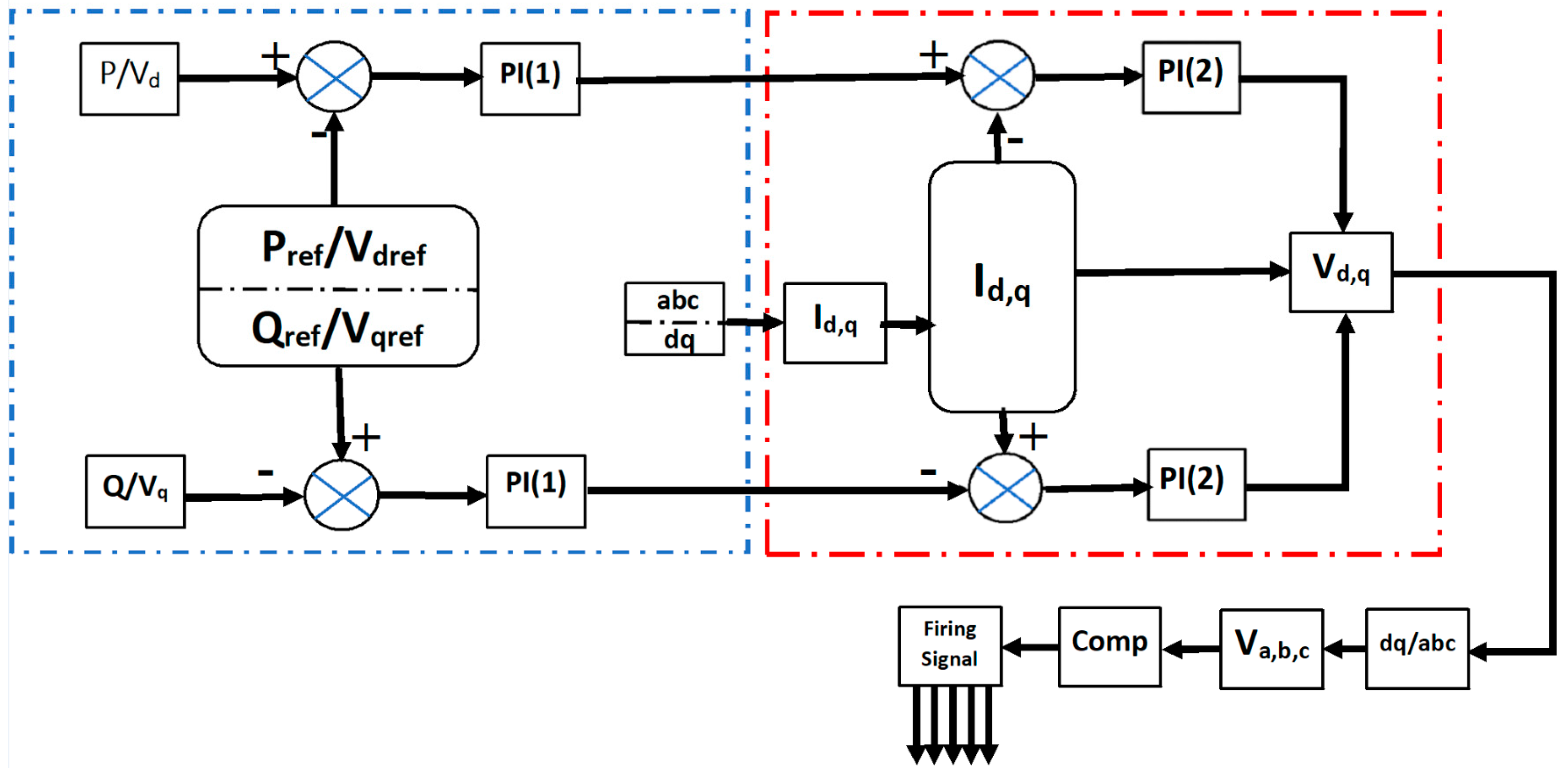
The systems for both controllers employ an inverter-based cascaded vector control strategy that utilizes two control loops. In the network-connected mode, the internal loop regulates the direct and quadrature axis current constituents (Id, Iq), while the external loop regulates the real and imaginary powers (P, Q) to maintain a constant terminal voltage and frequency. The conversion between the stationary frame and the d-q frame is obtained by the use of a phase-locked loop (PLL). In the island mode, the d and q axis terminal voltages (Vd, Vq) are controlled by the external PI controller loop, while the Id and Iq currents are managed by the inner loop. The (a, b, and c) reference voltage frames are obtained by converting the Vdn and Vqn outputs of the cascaded control. A triangular wave carrier with a frequency of 1980 Hz is compared to these voltages to establish the inverter firing signal for the IGBT switches. Figure 2 illustrates the cascaded vector control method for both network-connected and autonomous modes.
Here, Id and Iq represent the direct and quadrature axis components of the inverter current, Vd and Vq represent the terminal voltage d and q axis components, Vdref and Vqref represent the direct and quadrature axis components of the reference voltage, and Vdn and Vqn are the d and q axis constituents of the actual converter output produced by the cascaded control.

4. Modeling Stage

In this paper, the authors use the central composite response surface methodology (CCRSM) to model the PI and PIA controllers. The CCRSM method is a statistical tool that can be utilized for analyzing and modeling power systems [41,42]. It involves modeling the relationship between response and design variables, using a fitting technique. In this research, a PSCAD/EMTDC simulated system was employed to establish a CCRSM model for each scenario. The minimum terminal voltage provides the CCRSM inputs. A second-order response surface model can then be created using the CCRSM technique. The MINITAB software package has been utilized to implement the CCRSM model [43,44].

4.1. Variables and Levels Selection

In this study, the design variables for PIA controllers (1) and (2) are chosen as (kpi), (tii), (kai), (ai), and (bi), while for PI controllers (1) and (2), only the (kpi) and (tii) constants are selected as the design variables. The design is categorized into three levels: level (1) indicates the lowest value, level (2) indicates a mean value, and level (3) indicates the highest value of the design variable. Table 2 and Table 3 provide the variables’ magnitudes and levels. These levels are obtained initially via trial and error by running the PSCAD model and finding a suitable range where the system is stable for both the suggested controllers.

4.2. PSCAD/EMTDC Program Calculation

The computations in the PSCAD application are then run for each simulation. Table 4 and Table 5 list the minimum terminal voltage Vt values for the microgrid when the PI and PIA controllers are subject to a ‘three lines to ground’ fault, respectively. This scenario is chosen for use in the system design because it is a worst-case scenario that may occur in the power system; thus, the outcomes can be used for other scenarios.

4.3. Central Composite Response Surface Empirical Target Determination

At this stage, the system is modeled on the MINITAB package to obtain a second-order polynomial function in the case of system exposure to three phases with a ground fault; the objective function is the maximization of the minimum terminal voltages. Equations (8) and (9) represent the polynomial functions obtained from the CCRSM model for the PI and PIA controllers, respectively [14]:
V t i = c 1 + c 2 k p 1 + c 3 t i 1 + c 4 k p 2 + c 5 k i 2 + c 6 k p 1 2 + c 7 t i 1 2 + c 8 k p 2 2 + c 9 t i 2 2 + c 10 k p 1 t i 1 + c 11 k p 1 k p 2 + c 12 k p 1 t i 2 + c 13 k p 2 t i 1 + c 14 t i 1 t i 2 + c 15 k p 2 t i 2
V t i = c 1 + c 2 k p i 1 + c 3 t i 1 + c 4 k a i 1 + c 5 a i 1 + c 6 b i 1 + c 7 k p i 2 + c 8 t i 2 + c 9 k a i 2 + c 10 a i 2 + c 11 b i 2 + c 12 k p i 1 2 + c 13 t i 1 2 + c 14 k a i 1 2 + c 15 a i 1 2 + c 16 b i 1 2 + c 17 k p i 2 2 + c 18 t i 2 2 + c 19 k a i 2 2 + c 20 a i 2 2 + c 21 b i 2 2 + c 22 k p i 1 t i 1 + c 23 k p i 1 k a i 1 + c 24 k p i 1 a i 1 + c 25 k p i 1 k p i 2 + c 26 k p i 1 k a i 2 + c 27 k p i 1 a i 2 + c 28 k p i 1 b i 2 + c 29 t i 1 k a i 1 + c 30 t i 1 a i 1 + c 31 t i 1 k p i 2
where i = 1, 2, 3 and c1, c2…, c11 represent the polynomial function equation constants extracted from the CCRSM for each controller, as shown in Table 6 and Table 7.

5. Optimizing Stage

5.1. Driving Training-Based Optimization (DTBO)

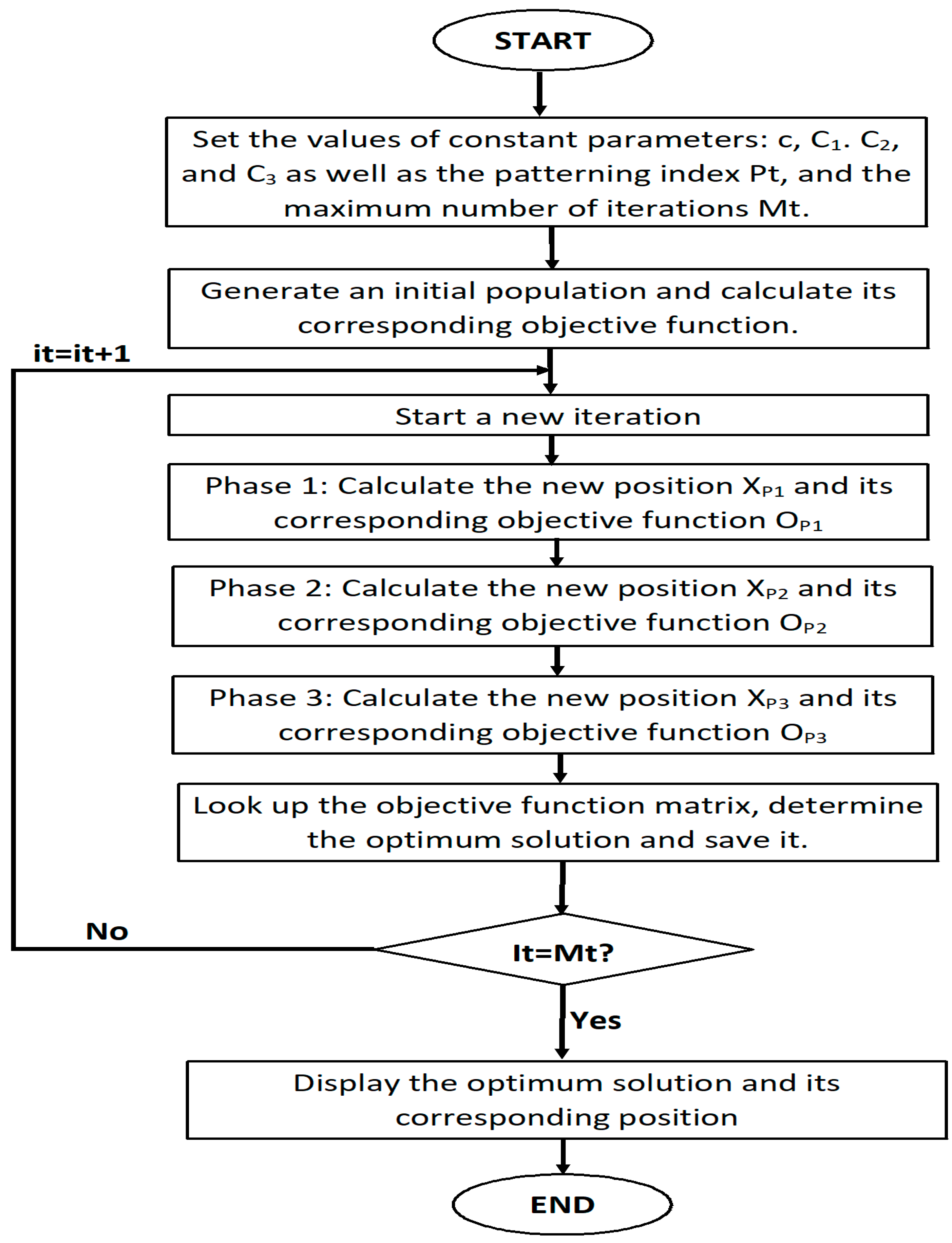
Driving training-based optimization (DTBO) represents a new metaheuristic algorithm that is based on imitating human actions when learning to drive [45,46,47,48,49,50,51]. Finding the optimum solution comprises three update phases based on exploration and exploitation. The first update phase of the DTBO algorithm is based on the trainee driver’s selection of the driving instructor and subsequent training in driving under the chosen teacher (exploration). The equation for updating the position of the candidate solution is calculated using Equation (3):
X P 1 , i = x p 1 , i + c · ( d i C 1 · x p 1 , i ) O d , i < O P 1 , i x p 1 , i + c · ( x p 1 , i d i ) O t h e r w i s e
where XP1,i is the new position for the ith candidate solution for the first phase, xp1,i is the previous position for the ith candidate solution for the first phase, di is the ith dimension of the driving instructor’s matrix, Od,i is the objective function value of the driving matrix for phase 1, OP1,i is the objective function value of the previous position for phase 1, C1 is a number randomly selected from the set of [1,2], and c is a random number in the interval [0, 1].
In the second phase, the trainee driver imitates the instructor, trying to mimic all the instructor’s actions and driving techniques. The members of the DTBO algorithm are moved to a different position inside the search space, enhancing the DTBO’s exploratory power. The position-updating equations for phase 2 are given in Equations (4)–(6):
P t = 0.01 + 0.9 ( 1 i t M t )
X P 2 , i = P t · x p 2 , i + 1 P t · d i
X i = X P 2 , i ,   O d , i < O P 2 , i x p 2 , i , O t h e r w i s e
where XP2,i is the new position for the ith candidate solution for the second phase, xp2,i is the previous position for the ith candidate solution for the second phase, Pt is the patterning index, it is the current iteration, Mt is the maximum number of iterations, Od,i is the objective function value of the driving matrix for phase 2, and OP2,i is the objective function value of the previous position for phase 2.
Finally, the third stage relies on each student driver’s personal practice in order to strengthen and improve their driving abilities. In this phase, each student driver aims to grow even closer to his or her best level of abilities (exploitation). Equation (9) provides the position update for phase 3, while the flow chart for DTBO is given in Figure 3:
X P 3 , i = x p 3 , i + 1 2 C 2 · C 3 · 1 i t M t · x p 3 , i
where XP3,i is the new position of the ith candidate solution for the third phase, xp3,i is the previous position of the ith candidate solution for the third phase, C2 is the random real number in the interval [0, 1], and C3 is the constant, set to 0.05.

5.2. HDTPS

It is important to note that every optimization method has its own limitations and strengths. No single optimization algorithm can effectively solve all optimization problems. As a result, recent research has trended toward using hybrid optimization approaches, for a more precise and dependable solution. PSO is one of the most widely used algorithms in hybrid optimization, which is why this paper proposes a hybrid approach combining the PSO and DTBO algorithms. First, PSO is utilized to determine the appropriate range when searching for optimal control gains. Then, the DTBO is used to identify more precise values within the range found by PSO, leading to an improved voltage profile for the microgrid.
In this paper, the optimization process is carried out using the HDTPS technique. The optimized gains for both controllers are obtained in the case of a ‘three lines to ground’ fault. The gains for the mentioned scenario are taken as gains in the case where running the other scenarios as the ‘three lines to ground’ fault is the worst fault that could occur in the power system. The optimization is carried out again, using PSO for validation of the results obtained from the HDTPS optimization technique. The maximum number of iterations, as well as the population size, is set to 100. These settings are fixed for both the PSO and hybrid simulations. The optimized PI and PIA controllers’ constants that were obtained via the two optimization techniques are listed in Table 8.

6. Simulation Results

The model was simulated using the PSCAD/EMTDC package. At t = 2 s, the grid switched to an autonomous mode; at t = 5 s, the system was subjected to either symmetrical or unsymmetrical faults or load variation. The symmetrical and unsymmetrical faults were sustained for 0.09 s before clearance. Load variability was caused by inserting a shunt resistor, after which the load reached 152 Ω.

6.1. Controller Performance Comparison Using HDTPS and PSO

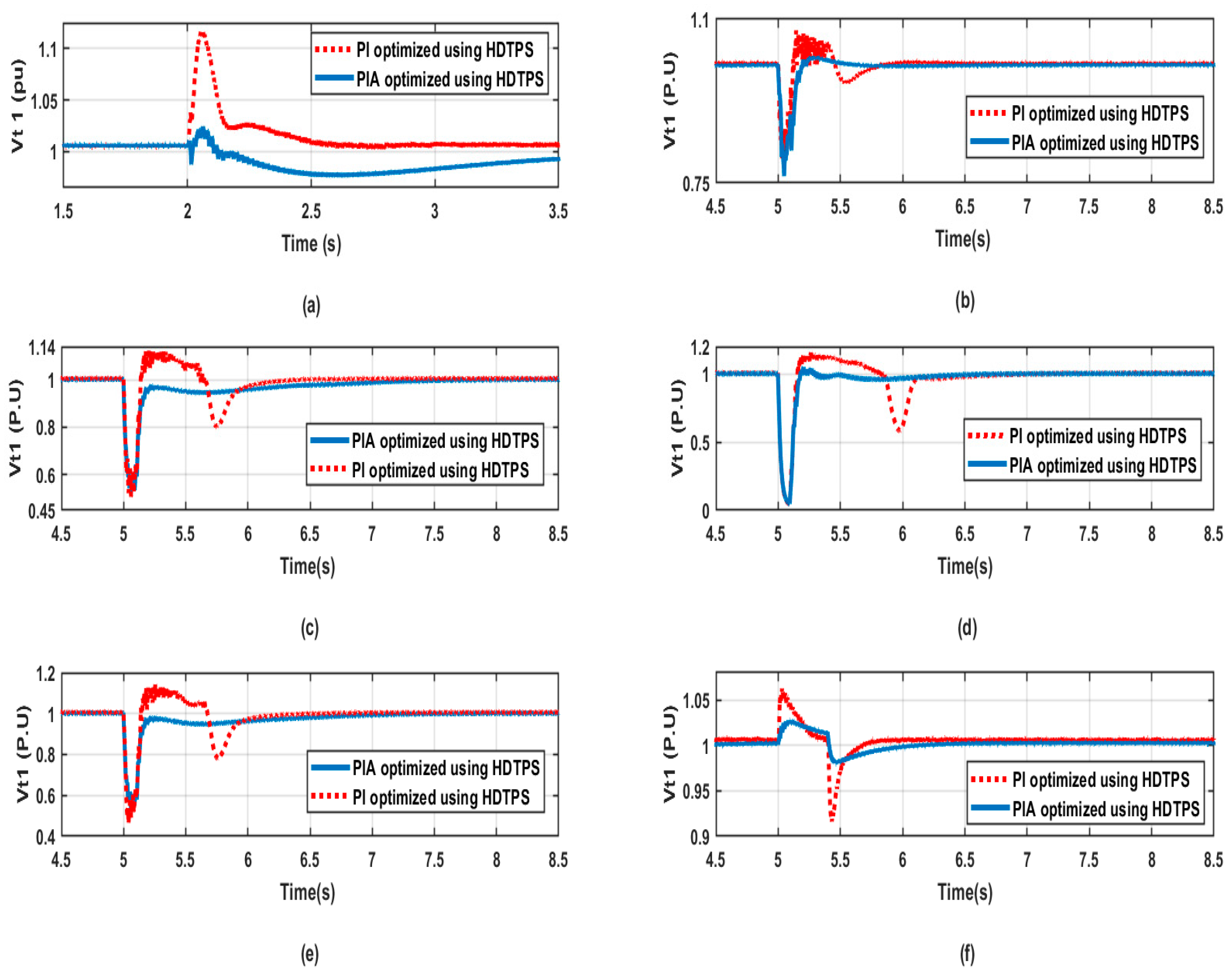
A comparison was made between the PI and PIA controllers by subjecting the system to various suggested scenarios: system transformation from the grid mode to the island mode, subjecting the system to different symmetrical and unsymmetrical faults, and load variability. Figure 4 illustrates the output terminal voltages for the PI and PIA controllers, optimized by using a hybrid technique for the DEG1.
Clearly, the PIA controller outperformed the PI controller, as demonstrated by the significantly improved voltage profile of the microgrid. The optimized PIA controller produced superior results compared to the optimized PI controller, particularly in the case of a three-line fault, where it exhibited a smaller undershoot and overshoot. Moreover, the PI controller sustained a longer transient period compared to the PIA. Overall, the PIA controller improved the settling time, maximum overshoot, and minimum undershoot, resulting in a better microgrid voltage profile. The same results were obtained for the other two DEGs.
As an example, in the case of system transformation from the grid mode to the islanded mode, the maximum percentage overshoot decreased by around 90% when using the PIA controller. With the ‘single line to ground fault’ occurrence, the maximum percentage overshoot decreased by around 90%. As can be seen in the other fault scenarios, another undershoot occurred when using the PI controller, and the transient period was sustained for longer periods.
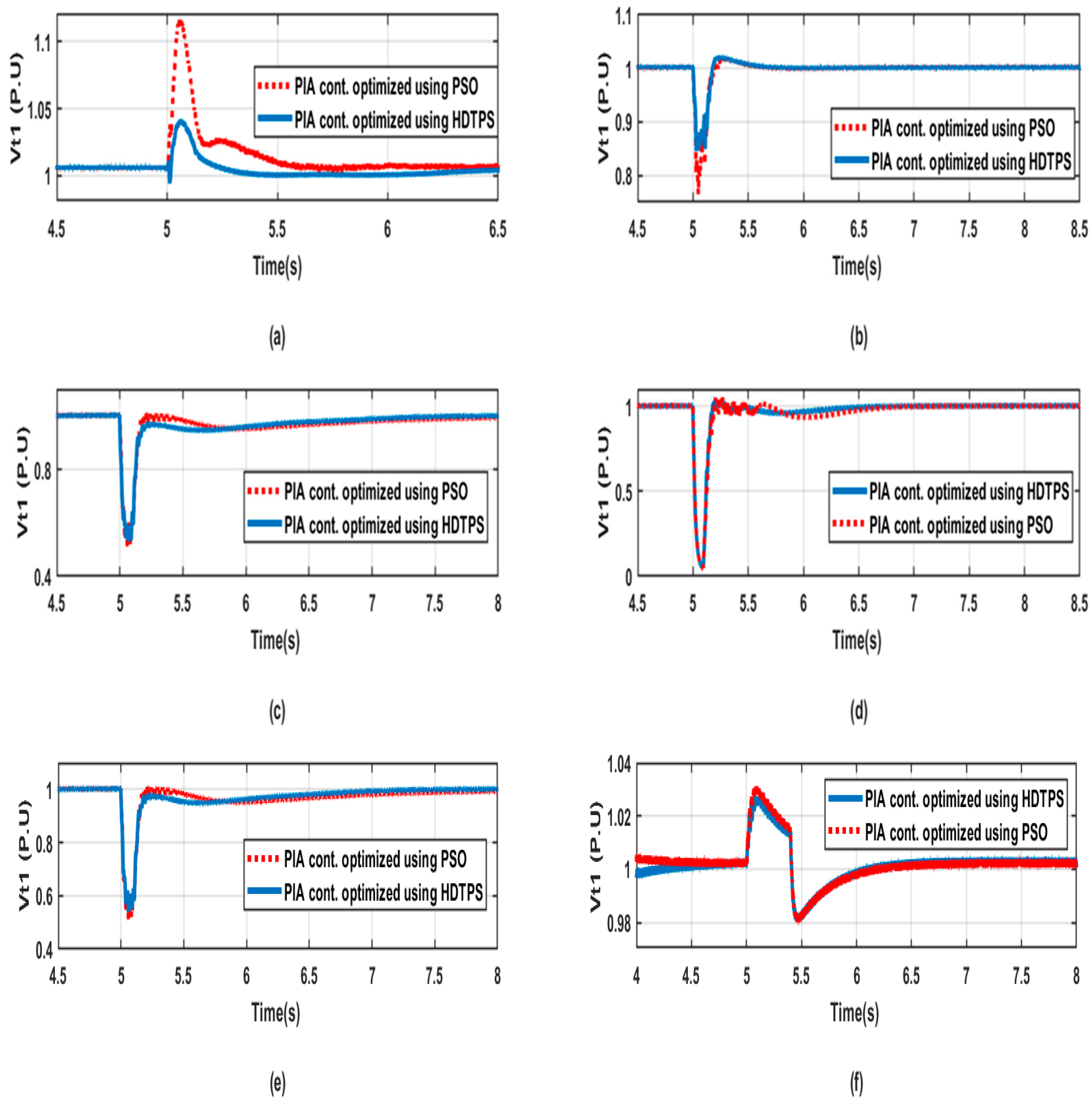
The simulations were carried out again for the purposes of comparing both controllers by optimizing their constants using only PSO, to validate the previous results from the hybrid methodology. The primary benefits of the PSO algorithm can be summed up as follows: easy implementation, robustness regarding control parameters, and computational efficiency in comparison to both mathematical algorithms and other metaheuristic optimization methods. The simulation results are shown in Figure 5 for all the suggested scenarios for DEG1.
Using the PSO technique, the optimized PIA controller showed a better voltage profile than that obtained from the optimized PI controller for the three DEGs. This means that the same results were obtained from both the hybrid and PSO methodologies, as is obvious from Figure 5. The same outcomes also occurred for DEG 2 and DEG 3.
As an example, in the case of a system transformation from grid mode to island mode, the maximum percentage overshoot decreased by around 90% when using the PIA controller. In the case of the ‘single line to ground’ fault occurrence, the minimum percentage overshoot decreased by about 80%, whereas the maximum percentage overshoot decreased by around 90%. As can be seen in the other fault cases, another undershoot occurred when using the PI controller, and the transient period was sustained for longer periods.
The improved voltage profile of the microgrid in all the studied scenarios shows that optimization using PSO, in the case of both controllers, was proven to offer better performance in terms of the PIA controller. As an example, when dealing with three-line faults using the optimized PIA controller, it provides a lower undershoot and overshoot, a shorter transient period, and a shorter settling time, compared to the optimized PI controller.

6.2. Optimization Technique Comparison (HDTPS and PSO)

In this section, a comparison is made between the two optimization techniques of HDTPS and PSO, as applied to the PIA controller to study the effectiveness of both techniques on controller operation in various scenarios. The results for the three DEGs are shown in Figure 6.
It is obvious from Figure 6 that the HDTPS technique improves the PIA controller’s operation. The optimized PIA controller, which used the HDTPS, significantly improved the voltage profile of the microgrid compared to when optimized using the PSO only. As an example, in the case of the system transformation from grid mode to island mode, the maximum percentage overshoot decreased by around 90% when using the HDTPS technique. In the case of the ‘single line to ground’ fault occurrence, the minimum percentage overshoot decreased by about 80%.
When the previously suggested scenarios were applied to the microgrid, the PIA controller optimized using HDTPS demonstrated a smaller undershoot and overshoot. Moreover, the transient period was sustained for a shorter time than in the other optimized technique. Overall, the HDTPS improved the voltage profile greatly in all the studied scenarios.

7. Discussion

After comparing the simulation results obtained from the PSCAD/EMTDC program, it was obvious that the PIA controller performed better than the PI controller in terms of the microgrid’s voltage profile, as shown by the results. Specifically, the optimized PIA controller outperformed the optimized PI controller, especially during a three-line fault, where it exhibited a smaller undershoot and overshoot. Additionally, the PIA controller has a shorter transient period compared to the PI controller. Overall, the PIA controller produces a better microgrid voltage profile by improving the settling time, maximum overshoot, and minimum undershoot.
To confirm the previous results that were obtained using the hybrid methodology, simulations were conducted again for both controllers by optimizing their constants, while using only the PSO algorithm. The PSO algorithm has several advantages, including its ease of implementation, robustness to control parameters, and computational efficiency compared to mathematical algorithms and other metaheuristic optimization methods. The results showed that the PIA controller that was optimized using the PSO technique produced a better voltage profile than the optimized PI controller. This indicates that the same results were obtained from both the hybrid and PSO methodologies.
Finally, on comparing the HDTPS and PSO methodologies in terms of PIA performance, HDTPS showed a better result than PSO in terms of enhancing the microgrid’s performance.

8. Conclusions

This article presents a new methodology to improve the performance of inverter-based distributed energy generation (DEG) systems and the microgrid’s voltage profile and stability by combining two optimization techniques, namely, the hybrid driving training-based and particle swarm optimization (HDTPS) approaches. In this approach, a vector-cascaded control scheme inverter was the utilized methodology. The hybrid DBTO and PSO algorithms were employed to optimize the parameters of the proportional–integral–adaptive (PIA) and the proportional–integral (PI) controllers. The optimization objective function was defined using a central composite response surface methodology (CCRSM). The efficiency of the suggested control method was evaluated using simulations conducted in the PSCAD/EMTDC environment. The simulation scenario involves a transformation of the system from a network-connected to an autonomous mode, and the microgrid is subjected to various fault conditions, including symmetrical and unsymmetrical faults and load variations. The results demonstrate the superior performance of the optimized PIA controller compared to the optimized PI controller, in terms of microgrid voltage profile enhancement. Moreover, the optimization was carried out again using only the PSO for validation of the outcomes of the HDTPS model, and the same results were obtained. Finally, a comparison was made between the two optimization techniques (the HDTPS and the PSO); the results show a better impact from using the HDTPS algorithm for optimizing the controller.

Author Contributions

D.A.Z., M.A.S. and H.M.H.: conceptualization and methodology; D.A.Z. and M.A.S.: validation and formal analysis; M.A. and Z.U.: investigation, visualization, and editing; H.M.H.: review and supervision. All authors have read and agreed to the published version of the manuscript.

Funding

This work was supported by King Saud University, Riyadh, Saudi Arabia.

Data Availability Statement

Not applicable.

Acknowledgments

This work was supported by the Researchers Supporting Project number (RSP2023R467), King Saud University, Riyadh, Saudi Arabia.

Conflicts of Interest

The authors declare no conflict of interest.

References

  1. Muqeet, H.A.; Javed, H.; Akhter, M.N.; Shahzad, M.; Munir, H.M.; Nadeem, M.U.; Bukhari, S.S.; Huba, M. Sustainable Solutions for Advanced Energy Management System of Campus Microgrids: Model Opportunities and Future Challenges. Sensors 2022, 22, 2345. [Google Scholar] [CrossRef] [PubMed]
  2. Zaki, D.A.; Hasanien, H.M.; El-Amary, N.H.; Abdelaziz, A.Y. Performance Enhancement of an Inverter-Based Decentralized energy generation System Using Evaporation Rate Based Water Cycle Algorithm. In Proceedings of the IEEE Conference on Power Electronics and Renewable Energy (CPERE), Aswan, Egypt, 23–25 October 2019; pp. 270–277. [Google Scholar]
  3. Liu, X.; Zhang, P.; Deng, X.; Sun, D. Hierarchical overvoltage predictive control scheme for a DFIG-based wind farm. Electr. Power Syst. Res. 2023, 217, 109172. [Google Scholar] [CrossRef]
  4. Chakraborty, A.; Maity, T. Integrated control algorithm for fast and accurate detection of the voltage sag with low voltage ride-through (LVRT) enhancement for doubly-fed induction generator (DFIG) based wind turbines. Control. Eng. Pract. 2023, 131, 105393. [Google Scholar] [CrossRef]
  5. Zolfaghari, M.; Gharehpetian, G.B.; Shafie-khah, M.; Catalão, J.P. Comprehensive review on the strategies for controlling the interconnection of AC and DC microgrids. Int. J. Electr. Power Energy Syst. 2022, 136, 107742. [Google Scholar] [CrossRef]
  6. Du, W.; Chen, Z.; Schneider, K.P.; Lasseter, R.H.; Nandanoori, S.P.; Tuffner, F.K.; Kundu, S. A Comparative Study of Two Widely Used Grid-Forming Droop Controls on Microgrid Small-Signal Stability. IEEE J. Emerg. Sel. Top. Power Electron. 2020, 8, 963–975. [Google Scholar] [CrossRef]
  7. Tan, K.H.; Li, M.Y.; Weng, X.Y. Droop Controlled Microgrid with DSTATCOM for Reactive Power Compensation and Power Quality Improvement. IEEE Access 2022, 10, 121602–121614. [Google Scholar] [CrossRef]
  8. Benadli, R.; Khiari, B.; Memni, M.; Bjaoui, M.; Sellami, A. An Improved Super-Twisting Sliding Mode Control for Standalone Hybrid Wind/Photovoltaic/Fuel Cell System Based on Energy Management of Battery/Hydrogen. J. Sol. Energy Eng. 2022, 144, 031003. [Google Scholar] [CrossRef]
  9. Trivedi, R.; Khadem, S. Implementation of artificial intelligence techniques in microgrid control environment: Current progress and future scopes. Energy AI 2022, 2, 100147. [Google Scholar] [CrossRef]
  10. Zaki, D.A.; Hasanien, H.M.; El-Amary, N.H.; Abdelaziz, A.Y. Tuning PI controllers for optimal migrogrid operation based on Artificial Neural Network. In Proceedings of the IEEE Conference on Power Electronics and Renewable Energy (CPERE), Aswan, Egypt, 23–25 October 2019; pp. 371–378. [Google Scholar]
  11. Sindi, H.F.; Alghamdi, S.; Rawa, M.; Omar, A.I.; Elmetwaly, A.H. Robust control of adaptive power quality compensator in Multi-Microgrids for power quality enhancement using puzzle optimization algorithm. Ain Shams Eng. J. 2022, 17, 102047. [Google Scholar] [CrossRef]
  12. Saxena, N.K.; Gao, W.D.; Kumar, A.; Mekhilef, S.; Gupta, V. Frequency regulation for microgrid using genetic algorithm and particle swarm optimization tuned STATCOM. Int. J. Circuit Theory Appl. 2022, 50, 3231–3250. [Google Scholar] [CrossRef]
  13. Guha, D.; Roy, P.K.; Banerjee, S. Performance evolution of different controllers for frequency regulation of a hybrid energy power system employing chaotic crow search algorithm. ISA Trans. 2022, 120, 128–146. [Google Scholar] [CrossRef] [PubMed]
  14. Rostom, D.Z.; Hasanien, H.M.; El Amary, N.H.; Abdelaziz, A.Y. Adaptive PI Control Strategy for Microgrid Performance Enhancement. Int. J. Energy Conv. 2019, 7. [Google Scholar] [CrossRef]
  15. Nagaraja, Y.; Devaraju, T.; Sankar, A.M.; Narasimhulu, V. PV and Wind Energy Conversion Exploration based on Grid Integrated Hybrid Generation Using the Cuttlefish Algorithm. Eng. Technol. Appl. Sci. Res. 2022, 12, 9670–9675. [Google Scholar] [CrossRef]
  16. Hasan, R.; Masud, M.S.; Haque, N.; Abdussami, M.R. Frequency control of nuclear-renewable hybrid energy systems using optimal PID and FOPID controllers. Heliyon 2022, 8, e11770. [Google Scholar] [CrossRef]
  17. Jagatheesan, K.; Shah, P.; Sekhar, R. Fractional Order PiλDµ Controller for Microgrid Power System Using Cohort Intelligence Optimization. Results Control. Optim. 2023, 11, 100218. [Google Scholar]
  18. Miret, J.; Balestrassi, P.P.; Camacho, A.; Guzmán, R.; Castilla, M. Optimal tuning of the control parameters of an inverter-based microgrid using the methodology of design of experiments. IET Power Electron. 2020, 13, 3651–3660. [Google Scholar] [CrossRef]
  19. Rey, J.M.; Vergara, P.P.; Castilla, M.; Camacho, A.; Velasco, M.; Martí, P. Droop-free hierarchical control strategy for inverter-based AC microgrids. IET Power Electron. 2020, 13, 1403–1415. [Google Scholar] [CrossRef]
  20. Zhang, Y.; Mohammadpour, S.A.; Wang, L.; Mohammadi-Ivatloo, B. Enhanced PI control and adaptive gain tuning schemes for distributed secondary control of an islanded microgrid. IET Renew. Power Gener. 2021, 15, 854–864. [Google Scholar] [CrossRef]
  21. Kavitha, P.; Karuvelam, P. A highly efficient optimized pi controller fed sepic converter for hybrid renewable sources based microgrid system. Microprocess. Microsyst. 2023, 16, 104797. [Google Scholar] [CrossRef]
  22. Gope, S.; Reddy, G.H.; Singh, K.M. Frequency regulation analysis for renewable bio generated autonomous multi-microgrid using moth flame optimized fractional order controller. Mater. Today Proc. 2022, 80, 753–761. [Google Scholar] [CrossRef]
  23. Jaber, A.S.; Abdulbari, H.A.; Shalash, N.A.; Abdalla, A.N. Garra Rufa-inspired optimization technique. Int. J. Intell. Syst. 2020, 35, 1831–1856. [Google Scholar] [CrossRef]
  24. Mansoorhoseini, P.; Mozafari, B.; Mohammadi, S. Islanded AC/DC microgrids supervisory control: A novel stochastic optimization approach. Electr. Power Syst. Res. 2022, 209, 108028. [Google Scholar] [CrossRef]
  25. Nafeh, A.A.; Heikal, A.; El-Sehiemy, R.A.; Salem, W.A. Intelligent fuzzy-based controllers for voltage stability enhancement of AC-DC micro-grid with D-STATCOM. Alex. Eng. J. 2022, 61, 2260–2293. [Google Scholar] [CrossRef]
  26. Anuraj, U.; Hameed, S.H.; Arunprakash, N.; Sajeeva, J.; Thanihaichelvan, T.; Kokulavasan, T.; Rajan, R.; Yuvaraj, M.; Thananjeyan, S.; Ahilan, K.; et al. Micro-grid Concept for Coordinated Control of Renewable Energy Power Plants and a Way to Integrate with Main Grid. In Proceedings of the 7th International Conference on Environment Friendly Energies and Applications (EFEA), Bagatelle Moka MU, Mauritius, 14–16 December 2022; pp. 1–6. [Google Scholar]
  27. Litwin, M.; Zieliński, D.; Styński, S. Remote synchronization of the microgrid to the utility grid without access to point of common coupling in the presence of disturbances. IEEE Access 2022, 10, 27819–27831. [Google Scholar] [CrossRef]
  28. Kaur, A.; Kaushal, J.; Basak, P. A review on microgrid central controller. Renew. Sustain. Energy Rev. 2016, 55, 338–345. [Google Scholar] [CrossRef]
  29. Arefi, A.; Shahnia, F. Tertiary controller-based optimal voltage and frequency management technique for multi-microgrid systems of large remote towns. IEEE Trans. Smart Grid 2018, 9, 5962–5974. [Google Scholar] [CrossRef]
  30. Shahnia, F.; Arefi, A. Defining the suitable adjacent microgrids to form a temporary system of coupled microgrids. In Proceedings of the IEEE Region 10 Conference, Singapore, 22–26 November 2016; pp. 1216–1219. [Google Scholar]
  31. Wu, P.; Huang, W.; Tai, N.; Liang, S. A novel design of architecture and control for multiple microgrids with hybrid AC/DC connection. Appl. Energy 2018, 210, 1002–1016. [Google Scholar] [CrossRef]
  32. Zhang, H.; Zhou, J.; Sun, Q.; Guerrero, J.M.; Ma, D. Data-driven control for interlinked AC/DC microgrids via model-free adaptive control and dual-droop control. IEEE Trans. Smart Grid 2017, 8, 557–571. [Google Scholar] [CrossRef]
  33. Nabatirad, M.; Razzaghi, R.; Bahrani, B. Autonomous power balance in hybrid AC/DC microgrids. Int. J. Electr. Power Energy Syst. 2023, 146, 108752. [Google Scholar] [CrossRef]
  34. Yu, H.; Niu, S.; Shao, Z.; Jian, L. A scalable and reconfigurable hybrid AC/DC microgrid clustering architecture with decentralized control for coordinated operation. Int. J. Electr. Power Energy Syst. 2022, 135, 107476. [Google Scholar] [CrossRef]
  35. Aryani, D.R.; Adi, F.S.; Kim, J.S.; Song, H. An improved model-based interlink converter control design in hybrid AC/DC microgrids. Energy Rep. 2022, 8, 520–531. [Google Scholar] [CrossRef]
  36. Li, S.; Li, Y.; Li, T. An autonomous flexible power management for hybrid AC/DC microgrid with multiple subgrids under the asymmetric AC side faults. Int. J. Electr. Power Energy Syst. 2022, 142, 107985. [Google Scholar] [CrossRef]
  37. Jithin, S.; Rajeev, T. Novel adaptive power management strategy for hybrid AC/DC microgrids with hybrid energy storage systems. J. Power Electron. 2022, 10, 1–3. [Google Scholar]
  38. Kamal, F.; Chowdhury, B. Model predictive control and optimization of networked microgrids. Int. J. Electr. Power Energy Syst. 2022, 138, 107804. [Google Scholar] [CrossRef]
  39. Manitoba HVDC Research Center. PSCAD/EMTDC Manual; HVDC Research Center: Winnipeg, MB, Canada, 2018. [Google Scholar]
  40. Milanesi, M.; Mirandola, E.; Visioli, A. A comparison between PID and PIDA controllers. In Proceedings of the IEEE 27th International Conference on Emerging Technologies and Factory Automation (ETFA), Stuttgart, Germany, 6–9 September 2022; pp. 1–6. [Google Scholar] [CrossRef]
  41. López-Meraz, R.A.; Hernández-Callejo, L.; Boza, L.O.; Ramos, J.A.; Hernández, J.J.; Gómez, V.A. Electric power management in a microgrid analyzing photovoltaic arrays and a turbine-generator system. Rev. Fac. Ing. Univ. Antioq. 2022, 104, 129–139. [Google Scholar] [CrossRef]
  42. Mansouri, S.; Zishan, F.; Montoya, O.D.; Azimizadeh, M.; Giral-Ramírez, D.A. Using an intelligent method for microgrid generation and operation planning while considering load uncertainty. Results Eng. 2023, 17, 100978. [Google Scholar] [CrossRef]
  43. Hussien, A.M.; Turky, R.A.; Alkuhayli, A.; Hasanien, H.M.; Tostado-Véliz, M.; Jurado, F.; Bansal, R.C. Coot bird algorithms-based tuning PI controller for optimal microgrid autonomous operation. IEEE Access 2022, 10, 6442–6458. [Google Scholar] [CrossRef]
  44. Hussien, A.M.; Kim, J.; Alkuhayli, A.; Alharbi, M.; Hasanien, H.M.; Tostado-Véliz, M.; Turky, R.A.; Jurado, F. Adaptive PI Control Strategy for Optimal Microgrid Autonomous Operation. Sustainability 2022, 14, 14928. [Google Scholar] [CrossRef]
  45. Dehghani, M.; Trojovská, E.; Trojovský, P. A new human-based metaheuristic algorithm for solving optimization problems on the base of simulation of driving training process. Sci. Rep. 2022, 12, 9924. [Google Scholar] [CrossRef]
  46. Feng, L.; Sun, X.; Tian, X.; Diao, K. Direct torque control with variable flux for an SRM based on hybrid optimization algorithm. IEEE Trans. Power Electron. 2022, 37, 6688–6697. [Google Scholar] [CrossRef]
  47. Khajehzadeh, M.; Keawsawasvong, S.; Sarir, P.; Khailany, D.K. Seismic analysis of earth slope using a novel sequential hybrid optimization algorithm. Period. Polytech. Civ. Eng. 2022, 66, 355–366. [Google Scholar]
  48. Kim, H.; Lee, T.H. Design-target-based optimization using input variable selection and penalty-Lagrange multiplier for high-dimensional design problems. Struct. Multidiscip. Optim. 2022, 65, 258. [Google Scholar] [CrossRef]
  49. Dey, B.; Raj, S.; Mahapatra, S.; Márquez, F.P. Optimal scheduling of distributed energy resources in microgrid systems based on electricity market pricing strategies by a novel hybrid optimization technique. Int. J. Electr. Power Energy Syst. 2022, 134, 107419. [Google Scholar] [CrossRef]
  50. Bakry, O.M.; Alhabeeb, A.; Ahmed, M.; Alkhalaf, S.; Senjyu, T.; Mandal, P.; Dardeer, M. Improvement of distribution networks performance using renewable energy sources-based hybrid optimization techniques. Ain Shams Eng. J. 2022, 13, 101786. [Google Scholar] [CrossRef]
  51. Shaheen, M.A.; Hasanien, H.M.; Alkuhayli, A. A novel hybrid GWO-PSO optimization technique for optimal reactive power dispatch problem solution. Ain Shams Eng. J. 2021, 12, 621–630. [Google Scholar] [CrossRef]
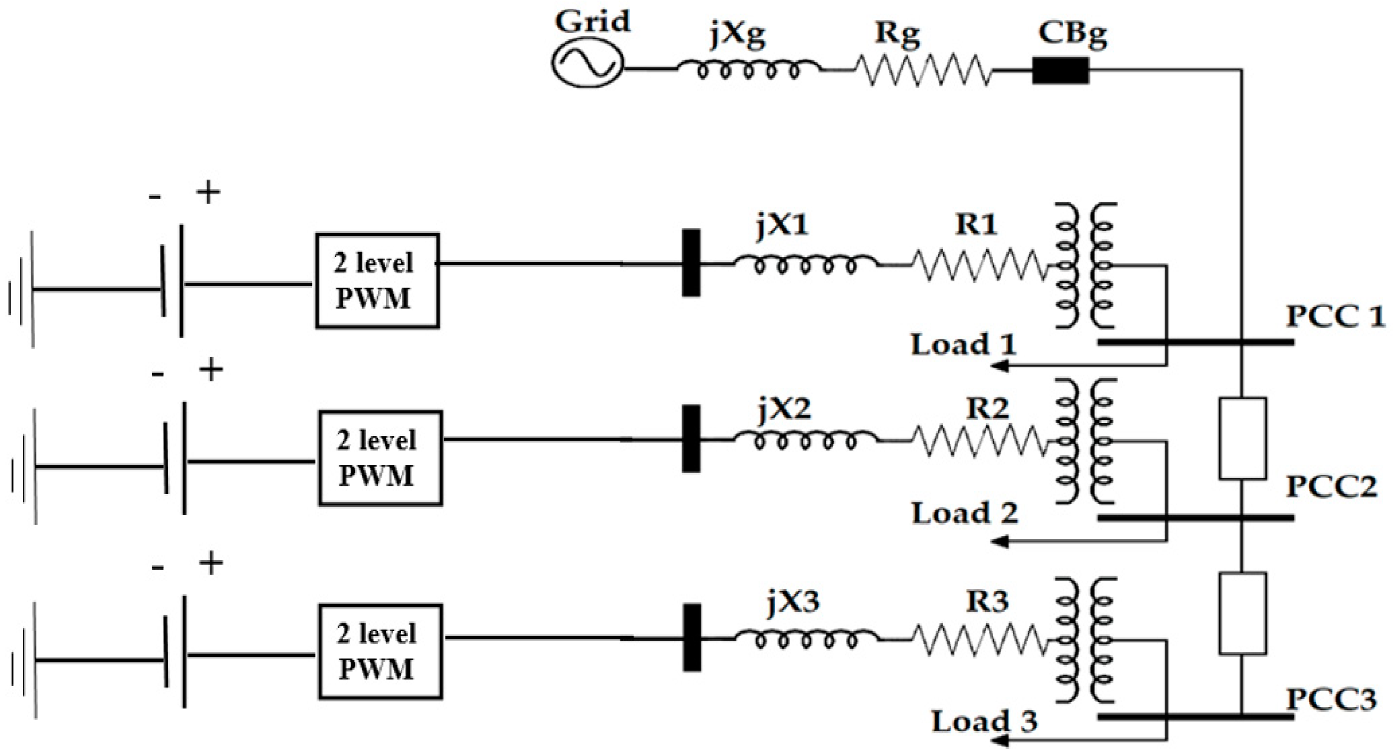
Figure 1. The modeled system using PSCAD/EMTDC.
Energies 16 04355 g001
Figure 2. The cascaded vector control scheme for both grid and islanded modes.
Energies 16 04355 g002
Figure 3. The DTBO algorithm flow chart.
Energies 16 04355 g003
Figure 4. DEG1 terminal voltage response using the PI and PIA controllers, optimized by the HDTPS for various scenarios: (a) System transformation from the grid mode to the autonomous mode. (b) ‘Line to ground fault’ occurrence scenario. (c) Line to line to ground fault occurrence scenario. (d) ‘Three lines to ground’ fault occurrence. (e) Double line fault occurrence. (f) Load variation scenario.
Energies 16 04355 g004
Figure 5. DEG 1 terminal voltage response using the PI and PIA controllers, optimized by only PSO for various scenarios: (a) System transformation from the grid mode to the autonomous mode. (b) ‘Line to ground’ fault occurrence scenario. (c) ‘Line-to-line to ground fault’ occurrence scenario. (d) ‘Three lines to ground’ fault occurrence. (e) Double-line fault occurrence. (f) Load variation scenario.
Energies 16 04355 g005
Figure 6. Comparison between the HDTPS and PSO algorithm for DEG 1. (a) System transformation from the grid mode to the autonomous mode. (b) ‘Line to ground’ fault occurrence scenario. (c) ‘Line-to-line to ground fault’ occurrence scenario. (d) ‘Three lines to ground’ fault occurrence. (e) Double line fault occurrence. (f) Load variation scenario.
Energies 16 04355 g006
Table 1. The DEG system data.
DEG dataVbase, low = 0.600 kV, Vbase, high = 13.800 kV,
Sb1 = 5 MVASb2 = 7.5 MVASb3 = 3.75 MVA
Transformer data∆/Y = 0.60/13.80 kV
Connected load dataLoad t1: Cl = 34 µF, Rl1 = 8.0 Ω, Rl2 = 150.0 Ω, Ll = 0.40 H
Load t2: C2 = 45.3 µF, R22 = 6.0 Ω, Rl2 = 150.0 Ω, L2 = 0.30 H
Load t3: C3 = 11.3 µF, R33 = 24 Ω, Rl2 = 150 Ω, L3 = 1.2 H
Transmission line dataT.L1: R1= 0.5 Ω, L1 = 0.0003 H
TL2: R2 = 1 Ω, L2 = 0.00070 H
Filter parametersRf = 1.5 mΩ, Xf = 3 mΩ, Quality factor = 50.0
Main network dataV = 13.80 KV, f = 60.0 Hz, Rg = 0.20 Ω, Lg = 0.00030 H
Table 2. The PI controller’s CCRSM design variables and levels.
DEG 1DEG 2DEG 3
Design Variable Level (PI)kp11ti11kp12ti12kp21ti21kp22ti22kp31ti31kp32ti32
Level 1 (−1)0.50.040.50.040.50.040.50.040.50.040.50.04
Level 2 (0)10.1210.1210.1210.1210.1210.12
Level 3 (1)1.50.21.50.21.50.21.50.21.50.21.50.2
Table 3. The PIA controller’s CCRSM design variables and levels.
Design Variable Level (PIA)Level 1
(−1)
Level 2 (0)Level 3
(1)
Design Variable Level (PIA)Level 1
(−1)
Level 2 (0)Level 3
(1)
kp11543kp22543
ti110.20.10ti220.20.10
ka1153.52ka2253.52
a11130012501200a22130012501200
b11300250200b22300250200
kp12543kp31543
ti120.20.10ti310.20.10
ka1253.52ka3153.52
a12130012501200a31130012501200
b12300250200b31300250200
kp21543kp32543
ti210.20.10ti320.20.10
ka2153.52ka3253.52
a21130012501200a32130012501200
b21300250200b32300250200
Table 4. The DEGs’ minimum terminal voltage in the case of a three-lines to ground fault occurrence (PI controller).
kp1ti1kp2ti2Vt1-lllgVt2-lllgVt3-lllg
10.1210.20.0980.11330.128
1.50.041.50.20.0970.113240.128
0.50.20.50.20.06680.0830.66
0.50.041.50.040.0740.085340.1014
1.50.040.50.040.09750.11280.128
10.1210.120.93440.11330.1285
10.121.50.120.0970.112450.12752
10.0410.120.0970.11320.128
10.1210.040.09780.113220.1285
1.50.20.50.20.09750.112760.13
10.1210.120.93440.11330.1285
0.50.21.50.20.071250.080.095
1.50.20.50.040.09740.11270.128
10.1210.120.93440.11330.1285
10.120.50.120.0980.11340.1287
0.50.040.50.20.0690.08060.097
0.50.040.50.040.0710.0820.098
10.1210.120.93440.11330.1285
0.50.21.50.040.0710.0820.095
10.1210.120.93440.11330.1285
0.50.1210.120.070.0820.0966
1.50.040.50.20.09750.1120.128
1.50.1210.120.0970.11220.127
10.1210.120.93440.11330.1285
0.50.20.50.040.070.07850.093
10.1210.120.93440.11330.1285
0.50.041.50.20.0730.08520.101
1.50.041.50.040.09750.1120.13
10.210.120.09840.1130.128
1.50.21.50.040.0980.11340.128
1.50.21.50.20.090.120.146
Table 5. The DEGs’ minimum terminal voltage in case of ‘three lines to ground’ fault occurrence (PIA controller).
kp1ti1ka1a1b1kp2ti2ka2a2b2Vt1-lllgVt2-lllgVt3-lllg
40.1015120020040.1013.512502000.0044240.057170.07
50.1013.5125025040.101212003000.043990.5680.06982
40.0022125025040.2512502500.0450250.06040.06397
40.23.5130025050.1013.513002500.4490.57980.6708
40.1015130030040.1013.512502000.04430.057140.07
30.1013.5125025040.101512003000.04390.05680.0696
40.0022125025040.002212502500.052840.068420.0839
40.23.5120025030.1013.513002500.04430.05690.0697
40.1013.5130020030.101512502500.044060.05670.0696
30.1013.5130025040.2212502500.0470.06040.0745
40.0025125025040.002512502500.052840.068660.08384
40.1012125030040.0023.512002500.05250.068240.0834
40.1015120030040.1013.512503000.0443220.0571310.07
40.23.5120025050.1013.512002500.044870.0580.0709
50.1012125025050.1013.513002500.04540.058740.07138
30.1013.5125025040.101213003000.0439260.0567640.0696
40.1012120030040.1013.512502000.0443820.05720.07
40.23.5130025030.1013.512002500.4430.0569360.06978
40.0025125025040.2212502500.0450.06040.069687
50.1013.5125025040.101513003000.0439860.058090.069762
30.0023.5125020040.1013.512502000.0445840.0574530.07019
30.23.5125020040.1013.512503000.0444170.0572320.070062
40.1013.5130030050.101512502500.0447270.0578490.07086
50.1013.5130025040.002212502500.0530260.068570.084176
30.1012125025030.1013.513002500.0437130.056380.069116
40.1012125020040.23.512002500.0464650.0598180.07325
40.23.5125025030.23.512502000.04570.0587570.072287
40.0023.5125025030.23.512503000.047170.0609330.07714
30.1015125025050.1013.513002500.045180.0583150.071161
50.25130030050.2513003000.47920.4850.4909
30.0022120020030.002212002000.551470.5560.5642
Table 6. The second-order polynomial function coefficients in the studied scenario for the PI controller.
ConstantsDEG1DEG2DEG3
c10.9050.021170.085
c21.270.154780.015
c32.99−0.03481.09
c41.130.00132−0.141
c52.99−0.02151.12
c6−0.619−0.063290.024
c714.60.0181.06
c8−0.5631 × 10−50.041
c9−14.60.0351.09
c100.0010.02355−0.673
c11−0.005−2 × 10−50.1434
c12−0.0010.00783−0.698
c13−0.0018 × 10⁻⁵−0.71
c14−0.050.06683.84
c15−0.010.00426−0.705
Table 7. The second-order polynomial function coefficients in the studied scenario for the PIA controller.
ConstantDEG1DEG2DEG3
c1159.9264170.5
c2−1.8892.357−3.785
c3−45.42−26.55−33.95
c40.1381.3231.115
c5−0.1373−0.151−0.1018
c60.004150−0.012890.002202
c70.1348−0.77290.2179
c8−0.52574.521−3.511
c9−0.07814−0.1635−0.07251
c10−0.1071−0.2619−0.1519
c11−0.01333−0.07532−0.04382
c120.04909−0.27530.324
c1310.156.597−1.027
c140.008846−0.02901−0.0358
c150.0000510.0000580.000034
c160.000080.0000260.000005
c17−0.010300.1297−0.1527
c182.40722.1816.95
c190.011680.12160.06735
c200.0000430.000110.000062
c210.0000150.0000830.000035
c22−0.3417−2.934−1.791
c23−0.04992−0.2799−0.2159
c240.0014600.0006740.003491
c250.054490.41950.3234
c26−0.000901−0.1720−0.09998
c27−1 × 10⁻⁸−0.0025510.000029
c280.0015060.0083950.006566
c29−0.14050.000444−0.03273
c300.036340.026390.02961
c310.0041691.3191.48
Table 8. The optimized gain values for both controllers.
PIA ControllerPI Controller
Optimized Gains Using HDTPSOptimized Gains Using PSOOptimized Gains Using HDTPSOptimized Gains Using PSO
kp11 = 4.6382kp11 = 3.41862kp11 = 1.5612kp11 = 1.4673
ti11 = 0.13994ti11 = 0.19731334
ka11 = 4.3485ka11 = 2.2254873
a11 = 1223.49a11 = 1376.7431ti11 = 0.22646ti11 = 0.1985
b11 = 292.3687b11 = 339.77794
kp12 = 3.14kp12 = 4.6312007
ti12 = 0.1130817ti12 = 0.19295647kp12 = 0.64132kp12 = 0.6135
ka12 = 2.11283ka12 = 2.6077231
a12 = 1244.535a12 = 1307.3856ti12 = 0.13742ti12 = 0.1537
b12 = 246.9423b12 = 259.24443
kp21 = 3.859339kp21 = 3.4101114kp21 = 0.42163kp21 = 0.5039
ti21 = 0.18897325ti21 = 0.057683216
ka21 = 2.1731026ka21 = 2.4704053
a21 = 1297.5596a21 = 1342.5901ti21= 0.060711ti21 = 0.0716
b21 = 290.04226b21 = 258.99485
kp22 = 4.4601331kp22 = 3.5387
ti22 = 0.16837334ti22 = 0.059242033kp22 = 0.82882kp22 = 0.8051
ka22 = 3.2468467ka22 = 2.6917
a22 = 1259.8421a22 = 1358.8685ti22 = 0.069886ti22 = 0.0711
b22 = 246.1586b22 = 235.72769
kp31 = 3.6314382kp31 = 4.1937448kp31 = 0.4648kp31 = 0.5548
ti31 = 0.04777053ti31 = 0.15264061
ka31 = 2.4095915ka31 = 3.5112517
a31 = 1194.0056a31 = 1107.0271ti31 = 0.035788ti31 = 0.0442
b31 = 221.69729b31 = 180.10337
kp32 = 3.7879111kp32 = 4.0073627
ti32 = 0.05891ti32 = 0.1091544kp32 = 1.5369kp32 = 1.3686
ka32 = 2.4789045ka32 = 3.4360098
a32 = 1289.379a32 = 1282.3392ti32 = 0.091197ti32 = 0.1125
b32 = 207.19588b32 = 267.846
Disclaimer/Publisher’s Note: The statements, opinions and data contained in all publications are solely those of the individual author(s) and contributor(s) and not of MDPI and/or the editor(s). MDPI and/or the editor(s) disclaim responsibility for any injury to people or property resulting from any ideas, methods, instructions or products referred to in the content.