Abstract
Concentrating solar power (CSP) and thermal energy storage (TES) based on molten salts still lacks economic feasibility, with the material investment costs being a major drawback. Ferritic stainless steels are a comparatively cheap class of materials that could significantly contribute to cost reductions. The addition of aluminum to ferritic steel can result in self-passivation by forming a compact Al2O3 top layer, which exhibits significantly higher corrosion resistance to solar salt compared to the Cr2O3 surface layers typically formed on expensive structural alloys for CSP and TES, such as austenitic stainless steels and Ni-base super alloys. However, to date, no ferritic stainless steel combining Al2O3 formation and sufficient structural strength is available. For this reason, cyclic salt corrosion tests under flowing synthetic air were carried out on seven Laves phase-forming, ferritic model alloys (17Cr2-14Al0.6-1Nb2.6-4W0.25Si), using “solar salt” (60 wt. % NaNO3 and 40 wt. % KNO3). The Al content was varied to investigate the influence on the precipitation of the mechanically strengthening Laves phase, as well as the impact on the formation of the Al-oxide top layer. The W and Nb contents of the alloys were increased to examine their influence on the precipitation of the Laves phase. The salt corrosion experiments demonstrated that simultaneous self-passivation against a molten salt attack and mechanical strengthening by precipitation of fine Laves phase particles is possible in novel ferritic HiperFerSCR (salt corrosion-resistant) steel. Microstructural examination unveiled the formation of a compact, continuous Al2O3 layer on the surface of the model alloys with Al contents of 5 wt. % and higher. Furthermore, a stable distribution of fine, strengthening Laves phase precipitates was achieved in the metal matrix, resulting in a combination of molten salt corrosion resistance and potentially high mechanical strength by a combination of solid solution and precipitation strengthening. These results show that high-strength ferritic alloys are suitable for use in CSP applications.
1. Introduction
Currently, extensive research is being conducted in the field of renewable energy [1,2,3]. The continuous innovation and optimization of solar tower power plant technology is helping to ensure that it can play an important role in the transition to a sustainable and low-carbon energy future. Solar tower power plants constitute a promising renewable technology for large-scale power and process heat generation [4]. These power plants use a field of mirrors (heliostats) to concentrate sunlight onto a central receiver mounted on the top of a tower. The concentrated solar energy is then used to generate high-temperature heat, usually by heating a heat transfer fluid, such as molten salt or pressurized steam. This heat is then used to drive a turbine and generate electricity. Solar thermal power plants typically use molten salts for heat transfer and storage [5]. The so-called “solar salt” is a combination of 60 wt. % NaNO3 and 40 wt. % KNO3 [6]. In the case of nitrate salts, partial dissociation occurs at higher temperatures, before they finally completely decompose at further increasing temperatures [7]. The overall efficiency of commercially operated solar thermal power plants is currently limited by the thermal stability of the solar salt, which makes process temperatures above 600 °C difficult to achieve [8]. Even at these temperatures, increased corrosion of metallic components occurs, requiring careful material selection [7]. Although the cost of solar thermal power plants has decreased by about 68% over the last 10 years [9], further cost reductions are needed to make solar thermal power plants competitive with other regenerative (wind, PV) and fossil energy technologies. An important aspect of cost reduction is the materials’ cost and durability. Ferritic alloys, which primarily consist of iron and chromium, offer a more cost-effective alternative for certain components in CSP, compared to commercially used nickel-based alloys. The abundance and widespread availability of iron contribute to the lower price of ferritic alloys. Additionally, chromium, the main alloying element in ferritic alloys, is more affordable compared to nickel, molybdenum, and other expensive alloying elements used in nickel-based alloys.
The development of Al2O3-forming stainless steels with high mechanical strength offers the potential for cost-effective structural material solutions. In the development of a cost-effective alternative, it is also important to ensure that it has good resistance to the heat transfer fluid used.
The aim of the presented alloy development was to combine the strengthening by precipitation of intermetallic Laves phase particles, known from ferritic “HiperFer” [10,11] alloys, with the formation of a salt corrosion-resistant oxide surface layer. Laves phases form a large class of intermetallic compounds that have tended to be considered detrimental phases to avoid [12]. However, with proper control of the precipitation process, Laves phases can serve as strengthening particles [10,11,13,14,15]. The main Laves phase-forming elements, W, Nb, and Si, strongly influence the mechanical properties by modifying the solid solution and precipitation strengthening effects.
By using model alloys, each weighing 100 g, alloying elements such as Al, Nb, and W were varied to investigate the influence of alloy chemistry on Al2O3 formation, and the precipitation of fine, long-term stable Laves phase particles in the ferrite matrix. Following the corrosion experiments, a detailed microstructure investigation was carried out with qualitative and quantitative evaluation of the particle size distribution (FE-SEM) and chemistry (EDX), as well as surface layer formation (FE-SEM).
2. Materials and Methods
2.1. Materials and Preparation
In this study, seven ferritic model alloys, each weighing 100 g, were investigated. The Al content was varied to investigate its effect on the precipitation of the Laves phase and the formation of the Al-oxide top layer. The W and Nb contents were also increased to examine the impact on the precipitation of the Laves phase. W, Nb, and Si were used for combined solid solution and precipitation hardening. In FeCrAl alloys, Nb is an essential component in the precipitation of the Laves phase [11,16,17]. Additionally, it hinders the occurrence of intergranular corrosion by preventing the formation of chromium carbides along grain boundaries [18]. The addition of W facilitates solid solution hardening and enhances the volume fraction of the Laves phase [17]. The intermetallic Laves phase particles, (Fe,Cr,Si,Al)2(Nb,W), significantly enhance the mechanical strength of these alloys [19]. Moreover, the addition of Si promotes the formation and stabilization [20,21] of the Laves phase, consequently increasing the service life of FeCrAl steel components. This is achieved by improving the adhesion of the protective oxide layers [22].
The model alloys were prepared under argon in a cold levitation crucible at normal pressure using high-purity raw materials. Investigations were then carried out to determine the homogeneous distribution of the alloying elements in the model alloys. The distribution of the alloying elements was largely homogeneous, and no segregations were detected after annealing for homogeneity. The chemical compositions of the model alloys (analyzed by inductively coupled plasma optical emission spectroscopy (ICP-OES); C, S, and N analyzed by infrared absorption) are presented in Table 1.

Table 1.
Chemical compositions (wt. %) of the ferritic model alloys.
After performing solution annealing, specimens with dimensions of 10 mm × 10 mm × 1 mm were extracted from the melts using electrical discharge machining. In accordance with ISO 17245:2015 [23], the surfaces and edges of these specimens were meticulously ground using 600-grit SiC paper to ensure consistent initial conditions in terms of surface roughness. Subsequently, the specimens were cleaned with ethanol and dried using hot air.
In air, temperatures of at least 1000 °C or higher are normally required for the formation of a protective α-Al2O3 layer on metal surfaces of FeCrAl alloys [24,25]. At temperatures above 1350 °C, significantly accelerated oxidation kinetics can occur, primarily driven by the formation of iron oxides [24]. To investigate the corrosion attack of the solar salt on a preformed Al2O3 layer, one sample per model alloy was annealed at 1100 °C for one hour in laboratory air. This temperature was selected to avoid uncontrolled precipitation of particles of the Laves phase, which can occur below 1050 °C [20]. Figure 1 shows an SEM image and a photograph of each model alloy before exposure to solar salt. In the pre-oxidized model alloys 4W 1Nb 3.5Al and 4W 1Nb 5Al, coarse Laves phase precipitates were still present. Due to the increased W and Nb contents, pre-oxidation temperatures of more than 1100 °C were apparently necessary to avoid uncontrolled precipitation of the Laves phase. After the heat treatment experiments, suitable pre-oxidation parameters (1175 °C/1 h) could be determined for these two model alloys, too. Samples treated with the optimized pre-oxidation parameters will be aged in solar salt in future work.
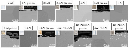
Figure 1.
Scanning electron (SEM) micrographs (top left: inlay light optical photographs showing specimen surface color) of the cross-sections of the specimens before corrosion testing.
2.2. Experimental Methods
Discontinuous salt corrosion testing of alloy specimens was carried out by placing them inside salt-filled alumina crucibles for a total of 2000 h at 600 °C in a tube furnace under the flow of synthetic air, with a flow rate of 10 sl/h. For this study, a mixture consisting of 60 wt. % NaNO3 (supplied by BASF SE, Ludwigshafen, Germany) and 40 wt. % KNO3 (supplied by Haldor Topsoe, Lyngby, Denmark) was prepared. As the solar salt creeps out of the specimen containers with the aging time, fresh solar salt was replenished every 500 h to ensure continuous coverage of the alloy specimens. The specimens were weighed every 250 h to calculate their individual mass changes according to DIN 50905-1 [26]. Further details regarding the equipment and testing methodology for salt corrosion behavior can be found in [12].
High-resolution scanning electron images (SEM) with a resolution of 4096 × 3072 pixels were acquired to determine the particle size distribution and the widths of the particle-free zones at grain boundaries, which are characteristic features of HiperFer-type steels [20,21,27], as well as below the surface oxide layer. The images were quantitatively analyzed using the OLYMPUS Stream Desktop software package, and the method described by Lopez et al. [21], which has been successfully applied to Laves phase-strengthened alloys, was employed.
3. Results and Discussion
3.1. Discontinuous Corrosion Testing
For the model alloy with the lowest Al content of 2 wt. % (2 Al), a strong mass increase of about 0.875 mg/cm2 was observed in the first 250 h (cf. Figure 2a). In the case of pre-oxidized 2 Al, the mass loss was even higher at about 1.625 mg/cm2. From 500 h until the end of the experimental period of 2000 h of aging in solar salt, only net losses were observed, ranging from 0.167 mg/cm2 to 0.792 mg/cm2. These mass losses, which were even higher in the case of pre-oxidized 2 Al, result from spallation of the oxide layer and indicate insufficient adhesion to the base material. Obviously, the Al content of 2 wt. % is too low to form a protective top layer. The fact that Al is simultaneously consumed by the precipitation of Laves phase within the ferrite matrix may worsen the situation. In comparison to the 2 Al alloy, the mass gain of the 3.5 Al steel was relatively low, especially for the pre-oxidized 3.5 Al. The slight increase in mass gain for the 3.5 Al alloy in the first 500 h indicates uniform, slow oxide film growth. This could also be observed for the model alloys with an increased Al content up to 5 wt. % Al (cf. Figure 2b) and for the model alloys with increased W and Nb contents (cf. Figure 2c).
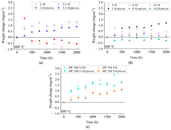
Figure 2.
Weight changes of corrosion specimens during discontinuous annealing in solar salt at 600 °C: (a) low Al content, (b) high Al content, and (c) high W and Nb contents.
When considering the mass changes of the model alloys with varying Al content, it was demonstrated that pre-oxidation had a detrimental effect, as seen by the increased mass change in the case of the 5 Al alloy and the increased mass losses in the case of the 14 Al alloy.
The increase in W and Nb contents in combination with an increase in Al content from about 3.5 wt. % to about 5 wt. % seemed to result in a lower mass change (cf. Figure 2c). After the first 250 h, the mass increase of 4W 1Nb 3.5Al (1.083 mg/cm2) was about three times higher than that of 4W 1Nb 5Al (0.417 mg/cm2). Regarding 4W 1Nb 3.5Al and 4W 1Nb 5Al alloys, pre-oxidation resulted in similar mass changes, but compared to the other model alloys, 4W 1Nb 3.5Al exhibited a comparatively higher mass increase.
Comparing the weight changes of 4W 1Nb 3.5Al and 4W 1Nb 5Al, it can be concluded that the increased W and Nb contents, due to the interaction of oxide layer growth and Laves phase precipitation, also required an increased Al content to obtain a slow-growing oxide layer.
When considering the higher-grade model alloys, a clear influence of the Al content on the mass change was observed (cf. Figure 2a,b). An Al content of 3.5 wt. % and above ensured a consistently low mass change. With increased W and Nb contents, an Al content of 5 wt. % was necessary for this effect. Therefore, higher W and Nb contents require higher Al contents to ensure sufficient availability of Al for the formation of a stable Al2O3 top oxide layer, indicating further potential for optimization of strength (due to higher W and Nb contents [24]), while maintaining high salt corrosion resistance. At an Al content of 14 wt. %, the mass change behaved significantly differently compared to the other model alloys. Over the entire test period of 2000 h, there were only small mass increases of up to 0.208 mg/cm2. In the case of the pre-oxidized variant, there were small mass losses of up to 0.291 mg/cm2 over the entire testing period.
SEM surface examination results, including associated light photographic images of the specimen surfaces, are presented in Figure 3. In the photographs of the specimen surfaces, the oxide layer appears reddish-brown for specimens with Al contents up to 3.5 wt. % and increased W and Nb contents, indicating an Fe-rich oxide layer. For Al contents from 5 wt. % to 14 wt. %, the sample surfaces appear grayish-beige, indicating an Al-containing oxide layer. For model alloys with Al contents up to 3.5 wt. %, on which bulky multi-layer Na-Fe-oxides formed, SEM exhibited indications of spallation, but no superficial cracks. These findings are consistent with the weight change curves presented in Figure 2. With a higher Al content, the oxide layer had a fine-grained morphology with fewer bulges, consisting of mixed Na-Fe-oxide forming on top of a mixed Al-Cr-Fe-oxide layer. The pre-oxidized specimen exhibited a coarser oxide layer, which was marked by the presence of surface bulges. Only mixed Al-oxide without bulges of Na-Fe-oxides was detected on the 14 Al alloy. In the sample cross-section of the 14 Al alloy (cf. Figure 4), a protective, continuous Al2O3 layer with a thickness of about 40 nm formed after 2000 h at 600 °C in solar salt. In contrast to the other model alloys, the 14 Al specimen did not form a uniform distribution of small Laves phase particles in the base metal during aging in solar salt. The Al2O3 layer of the pre-oxidized 14 Al was about 30 nm-thick, with comparatively large Laves phase precipitations underneath.
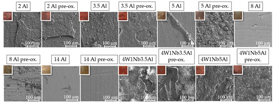
Figure 3.
SEM micrographs of the specimen surfaces after discontinuous corrosion tests in solar salt for 2000 h at 600 °C (top left: inlay light optical photographs showing specimen surface color).
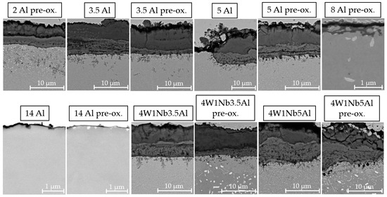
Figure 4.
SEM micrographs of the specimen cross-sections after discontinuous corrosion tests in solar salt for 2000 h at 600 °C.
The EDX element mappings of the cross-sections of expressive model alloys are displayed in Figure 5, Figure 6 and Figure 7. For the model alloys with lower Al contents of up to 3.5 wt. % (cf. Figure 5), the oxide formed in three layers: an intermediate layer composed of Cr-Na-Fe-oxide was formed between an upper layer consisting of Na-Fe-mixed oxide and a lower layer of Cr-Al-oxide on the steel base. This type of three-layer oxide film formation is already known from previous salt corrosion experiments with ferritic FeCrAl alloys [12]. Coarse AlN precipitates could be found below the oxide layer. As expected, intermetallic phase precipitates composed of Fe, Cr, Al, and W were observed in the base material. For the pre-oxidized 5 Al alloy, the oxide film formation was similar to the lower Al content variants (cf. Figure 6). For 5 Al, the multilayer oxide formation was only observed in the few bulky areas. In the flat areas, a thin and compact Al2O3 layer was found in the case of the 5 Al alloy.
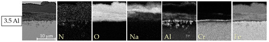
Figure 5.
Energy-dispersive X-ray element mappings of the cross-sections of the specimens with a low Al content of 3.5 wt. % after discontinuous corrosion tests in solar salt for 2000 h at 600 °C.
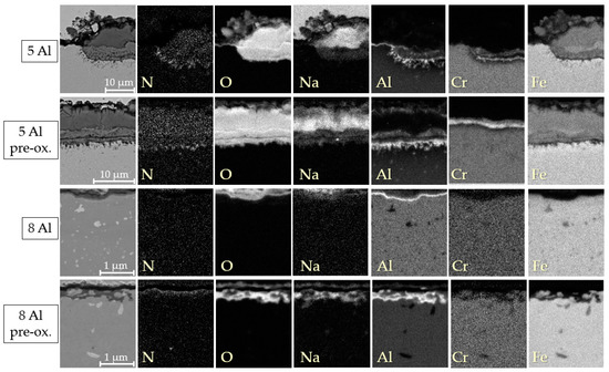
Figure 6.
EDX element mappings of the cross-sections of the specimens with high Al contents of 5 wt. % and 8 wt. % after 2000 h of discontinuous corrosion testing in solar salt at 600 °C.
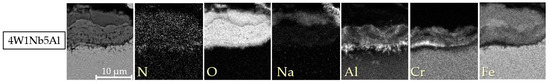
Figure 7.
EDX element mappings of the cross-sections of the specimens with high W and Nb content after discontinuous corrosion tests in solar salt for 2000 h at 600 °C.
Furthermore, AlN precipitates were detected below the multilayer oxide areas only. In contrast, below the thin, flat Al2O3 layers of the 8 Al alloys, no AlN precipitates were found. However, the disadvantage of pre-oxidation became evident when examining the 8 Al alloy with and without pre-oxidation. The oxide layer formed by pre-oxidation appeared to be incomplete, allowing the solar salt to permeate through. Consequently, internal oxidation by Na occurred. Pure Na-oxide, visible on top of the Al2O3 layer of the 8 Al alloys, could also be salt residues left behind during sample preparation. For the model alloys with increased W and Nb contents, the surface oxide also formed in layers, similar to the alloys with a low Al content (cf. Figure 7).
It is remarkable that a protective Al2O3 layer formed on top of the model steels during annealing in solar salt at the intermediate temperature of 600 °C, even in the absence of pre-oxidation in air, as previously observed in corrosion experiments in solar salt with a similar alloy composition and aging temperature [9]. The formation of Al2O3 at lower temperatures can be attributed to the interplay between the alloy composition and the corrosive environment containing oxygen. Increasing the Al content provides a greater availability of Al for oxide formation. Moreover, the presence of high Cr and Al contents in the alloy triggers the so-called third element effect [28]. As Cr exhibits a lower affinity for oxygen compared to Al, it facilitates the reduction of oxygen influx into the base metal, allowing Al to diffuse to the metal surface without precipitating as an internal oxide. Subsequently, once Al has diffused to the metal surface, it rapidly undergoes oxidation due to the presence of an oxygenated, corrosive environment that effectively wets the material surface.
These results imply that the alloy concept with all the tested variations of Al, W, and Nb has the potential for self-passivation upon exposure to solar salt. The reason for the Al2O3 formation at lower temperatures could be an interplay between the alloy composition and the oxygen-containing, corrosive environment.
3.2. Laves Phase Precipitation
Exemplary SEM micrographs of Laves phase precipitation in the 2 Al, 5 Al, 8 Al, 4W 1Nb 3.5Al, and 4W 1Nb 5Al model alloys after discontinuous corrosion tests in solar salt for 2000 h at 600 °C are presented in Figure 8. To assess the stability of the Laves phase particles during operation, the mean particle size and the widths of particle-free zones along high-angle grain boundaries were determined after exposure to solar salt for 2000 h at 600 °C (cf. Table 2). Associated size distribution histograms (particle frequency, i.e., fraction of particles within corresponding equivalent circle diameter ranges in relation to the overall number of particles counted) are depicted in Figure 9 and Figure 10.
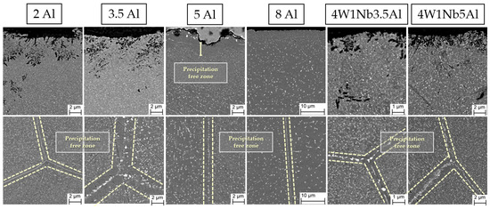
Figure 8.
SEM micrographs of Laves phase particle population after discontinuous corrosion tests in solar salt for 2000 h at 600 °C. The dashed lines mark the areas of the particle-free zones at the grain boundaries.
Table 2.
Mean equivalent circle diameters with standard deviations of Laves phase particles (investigated area depth: 100 to 600 µm), width of the particle-free zone near the surface (down to 6 µm depth), and at high-angle grain boundaries within the bulk material (depth of the investigated area: 100 to 600 µm) in the model alloys after discontinuous corrosion tests in solar salt for 2000 h at 600 °C.
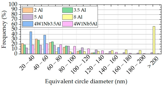
Figure 9.
Equivalent circle diameter distributions of precipitates in the model alloys (determined over an area of approximately 1450 µm2 each) after 2000 h of discontinuous corrosion testing in solar salt at 600 °C.
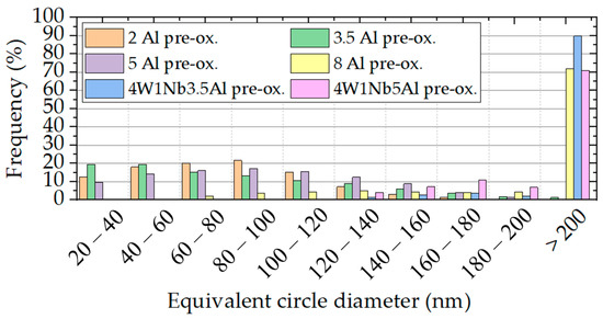
Figure 10.
Equivalent circle diameter distributions of precipitates in the pre-oxidized model alloys (determined over an area of approximately 1450 µm2 each) after discontinuous corrosion tests in solar salt for 2000 h at 600 °C.
Near-surface particle-free zones were found exclusively in the 5 Al and 8 Al pre-oxidized variants. In the case of the 8 Al alloy, on the other hand, a narrow region of much finer Laves phase precipitates below the oxide layer was encountered (cf. Figure 8). In the other samples, the particle size remained stable along the depth of the material. Due to pre-oxidation and with the increasing Al content, the particle-free zones in the bulk material expanded along the high-angle grain boundaries, which is typical [29] for HiperFer-type steels. Since Al2O3 is more stable than Cr2O3, there was reduced consumption of Al and Cr through surface oxidation. As a result, a larger amount of Al and Cr were available for the growth of the Laves phase in the pre-oxidized model alloys. In the untreated model alloys, the oxide layer formed during the corrosion experiment and consumed Al and Cr from the surface near the alloy matrix. This inhibited the nucleation and growth of Laves particles near the surface, as seen in 5 Al, 8 Al, and 8 Al pre-oxidized specimens. However, as the depth within the material increased, then consumption of Al and Cr at the surface no longer significantly affected the Laves phase formation, which consequently led to equalization of the particle sizes.
Looking at Figure 9 and Table 2, the Laves phase precipitates also tended to coarsen with the rising Al content. Pre-oxidation of the specimens before corrosion testing slightly enhanced this effect (cf. Figure 10). The pre-oxidation of the alloys with increased W and Nb contents led to particularly strong coarsening, because of the obviously unsuitable pre-oxidation parameters, which led to nucleation, growth, and/or incomplete dissolution of the Laves phase during pre-oxidation. The increase in W and Nb contents per se caused a decrease in the equivalent circle diameter. However, it is striking that at an elevated content of 14 wt. % Al, no Laves phase precipitates were detected after corrosion testing in solar salt. In principle, increasing the Al content seems to lead to coarsening and reduction of the number of Laves phase precipitation. Since the Laves phase precipitation can be influenced by heat treatment parameters [30], it can be assumed that higher temperatures are necessary for particle precipitation at an Al content of 14 wt. %.
4. Conclusions
Salt corrosion experiments were carried out at 600 °C for 2000 h on seven ferritic model alloys with different Al, W, and Nb contents. The key conclusions of the practical research presented here can be summarized as follows:
- For a low Al content of up to 3.5 wt. %, spallation of the formed surface oxide occurred. The oxide formed in three layers: an intermediate layer of Cr-Na-Fe-oxide between an upper layer of Na-Fe-mixed oxide and a bottom layer of Cr-Al-oxide adjacent to the steel substrate. Coarse AlN precipitates could be found below the oxide layer for an Al content of up to 5 wt. %. As expected, strengthening intermetallic Laves phase precipitates of Cr, Fe, W, Nb, and Al formed in the base material. Pre-oxidation proved detrimental due to increased mass changes and coarse, discontinuous oxide layers.
- The 14 Al formed a protective, continuous Al2O3 layer with a thickness of about 40 nm, but did not form small Laves phase particles in the base metal during aging in solar salt. For this reason, it is not considered a good candidate for structural applications, despite its superior salt corrosion resistance.
- Increased W and Nb contents necessitated a higher Al content to obtain slow-growing oxide layers, because of the interaction of oxide layer growth and Laves phase precipitation.
- Protective Al2O3 layers formed in solar salt at a moderate temperature of 600 °C, even without prior oxidation in air at a high(er) temperature. The alloying concept (in all the tested variations of Al, W, and Nb contents) exhibited potential self-passivation upon exposure to solar salt.
- The amount of strengthening Laves precipitates in the size range from 20 to 60 nm clearly correlated with increased W and Nb contents. Changes in the Al content in the range from 2 to 5 wt. % had a minor impact on the number of particles in the size range from 20 to 100 nm and are thus considered advantageous in terms of mechanical strength. In contrast, an Al content of 8 wt. % favored increased particle growth and should be avoided.
As a final summary, it can be stated that the presented HiperFerSCR steel type is a promising candidate for a significant reduction of investment costs in molten salt technology. It combines self-passivation in solar salt, mechanical strength, and low cost. For this reason, it could provide an enabling material solution for improving the competitiveness of CSP and TES equipment. However, it should be noted that despite extensive research efforts on the corrosion resistance of molten salts for solar energy applications, the underlying corrosion mechanisms are still not fully understood. Long-term tests or tests in practical operation are still necessary to ensure the reliability of the entire CSP-TES system.
Author Contributions
Conceptualization, F.A. and B.K.; methodology, F.A. and B.K.; investigation, F.A.; resources, B.K.; data curation, F.A.; writing—original draft preparation, F.A.; writing—review and editing, B.K. and F.A.; visualization, F.A.; supervision, B.K.; project administration, B.K.; funding acquisition, B.K. All authors have read and agreed to the published version of the manuscript.
Funding
This research was funded by the German Federal Ministry of Education and Research (BMBF) under grant number 03EE5048A, which is greatly appreciated.
Data Availability Statement
Data sharing is not relevant/appropriate.
Acknowledgments
The authors would like to extend their gratitude to D. Grüner and E. Wessel from Forschungszentrum Jülich GmbH for their assistance with the microstructural examination.
Conflicts of Interest
The authors have no conflict of interest to declare.
References
- Du, Z.; Liu, G.; Huang, X.; Xiao, T.; Yang, X.; He, Y. Numerical studies on a fin-foam composite structure towards improving melting phase change. Int. J. Heat Mass Transf. 2023, 208, 124076. [Google Scholar] [CrossRef]
- Malkawi, D.S.; Rabady, R.I.; Malkawi, M.S.; Al Rabadi, S.J. Application of Paraffin-Based Phase Change Materials for the Amelioration of Thermal Energy Storage in Hydronic Systems. Energies 2023, 16, 126. [Google Scholar] [CrossRef]
- Fabrykiewicz, M.; Cieśliński, J.T. Effect of Tube Bundle Arrangement on the Performance of PCM Heat Storage Units. Energies 2022, 15, 9343. [Google Scholar] [CrossRef]
- Guédez, R.; Topel, M.; Spelling, J.; Laumert, B. Enhancing the Profitability of Solar Tower Power Plants through Thermoeconomic Analysis Based on Multi-objective Optimization. Energy Procedia 2015, 69, 1277–1286. [Google Scholar] [CrossRef]
- Zaversky, F.; García-Barberena, J.; Sánchez, M.; Astrain, D. Transient molten salt two-tank thermal storage modeling for CSP performance simulations. Sol. Energy 2013, 93, 294–311. [Google Scholar] [CrossRef]
- Bonk, B.; Martin, C.; Braun, M.; Bauer, T. Material investigations on the thermal stability of solar salt and potential filler materials for molten salt storage. AIP Conf. Proc. 2019, 1850, 080008. [Google Scholar] [CrossRef]
- Aarab, F.; Kuhn, B.; Bonk, A.; Bauer, T. A New Approach to Low-cost, Solar Salt Resistant Structural Materials for Concentrating Solar Power (CSP) and Thermal Energy Storage (TES). Metals 2021, 11, 1970. [Google Scholar] [CrossRef]
- Kuizenga, A.M.; Cordaro, J.G. Preliminary Development of Thermal Stability Criterion for Alkali Nitrates; Sandia Technical Report SAND2011-5837C; Sandia National Laboratories: Albuquerque, NM, USA, 2011.
- IRENA. Latest Cost Trends in Renewable Power Generation Costs in 2020; International Renewable Energy Agency: Abu Dhabi, United Arab Emirates, 2021. [Google Scholar]
- Kuhn, B.; Fischer, T.; Fan, X.; Talik, M.; Aarab, F.; Yamamoto, Y. HiperFer-Weiterentwicklungs-Und Anwendungspotenziale. In Proceedings of the 43th FVWHT Vortragsveranstaltung Langzeitverhalten Warmfester Stähle und Hochtemperaturwerkstoffe, Online, 27 November 2020; p. 43. [Google Scholar]
- Kuhn, B.; Talik, M.; Fischer, T.; Fan, X.; Yamamoto, Y.; Lopez Barrilao, J. Science and Technology of High Performance Ferritic (HiperFer) Stainless Steels. Metals 2020, 10, 463. [Google Scholar] [CrossRef]
- Stein, F.; Leineweber, A. Laves phases: A review of their functional and structural applications and an improved fundamental understanding of stability and properties. J. Mater. Sci. 2021, 56, 5321–5427. [Google Scholar] [CrossRef]
- Hald, J. Microstructure and long-term creep properties of 9–12% Cr steels. Int. J. Press. Vessel. Pip. 2008, 85, 30–37. [Google Scholar] [CrossRef]
- Kobayashi, S.; Kimura, K.; Tsuzaki, K. Interphase precipitation of Fe2Hf Laves phase in a Fe–9Cr/Fe–9Cr–Hf diffusion couple. Intermetallics 2014, 46, 80–84. [Google Scholar] [CrossRef]
- Kobayashi, S. Formation of the Fe2Hf Laves Phase through Eutectoid Type Reaction of δ→γ+Fe2Hf in Ferritic Heat Resistant Steels. ISIJ Int. 2014, 55, 2. [Google Scholar] [CrossRef]
- Kuhn, B.; Talik, M.; Niewolak, L.; Zureka, J.; Hattendorf, H.; Ennis, P.J.; Quadakkers, W.J.; Beck, T.; Singheiser, L. Development of high chromium ferritic steels strengthened by intermetallic phases. Mater. Sci. Eng. A 2014, 594, 372–380. [Google Scholar] [CrossRef]
- Fan, X.; Kuhn, B.; Pöpperlová, J.; Bleck, W.; Krupp, U. Compositional Optimization of High-Performance Ferritic (HiperFer) Steels—Effect of Niobium and Tungsten Content. Metals 2020, 10, 1300. [Google Scholar] [CrossRef]
- Żuk, M.; Czupryński, A.; Czarnecki, D.; Poloczek, T. The effect of niobium and titanium in base metal and filler metal on intergranular corrosion of stainless steels. Weld. Technol. Rev. 2019, 91, 30–38. [Google Scholar] [CrossRef]
- Beck, T.; Kuhn, B.; Eckardt, T.; Singheiser, L. Microstructure, Creep and Thermomechanical Fatigue of Novel Solid Solution and Laves Phase Strengthened Cr2O3 and Al2O3 Forming Ferrites for Car Engine Exhaust and Heat Exchanger Systems. Trans. Indian Inst. Met. 2016, 69, 379–385. [Google Scholar] [CrossRef]
- Lopez Barrilao, J.; Kuhn, B.; Wessel, E. Microstructure and intermetallic particle evolution in fully ferritic steels. In Proceedings of the 8th International Conference on Advances in Materials Technology for Fossil Power Plants, Albufeira, Portugal, 11–14 October 2016; pp. 1029–1037. [Google Scholar]
- Lopez Barrilao, J. Microstructure Evolution of Laves Phase Strengthened Ferritic Steels for High Temperature Applications; Energie & Umwelt; RWTH Aachen University: Aachen, Germany, 2017; Volume 375, ISBN 978-3-95806-231-3. [Google Scholar]
- Klöwer, J. Factors affecting the oxidation behaviour of thin Fe-Cr-Al foils Part II: The effect of alloying elements: Overdoping. Mater. Corros. 2000, 51, 373–385. [Google Scholar] [CrossRef]
- ISO 17245:2015; Corrosion of Metals and Alloys—Test Method for High Temperature Corrosion Testing of Metallic Materials by Immersing in Molten Salt or Other Liquids under Static Conditions. ISO: Geneva, Switzerland, 2015.
- Kim, C.; Tang, C.; Grosse, M.; Steinbrueck, M.; Jang, C.; Maeng, Y. Oxidation Kinetics of Nuclear Grade FeCrAl Alloys in Steam in the Temperature Range 600–1500 °C. In Proceedings of the TOPFUEL 2021 Conference, Santander, Spain, 24–28 October 2021. [Google Scholar] [CrossRef]
- Gunduz, K.O.; Visibile, A.; Sattari, M.; Fedorova, I.; Saleem, S.; Stiller, K.; Halvarsson, M.; Froitzheim, J. The effect of additive manufacturing on the initial High temperature oxidation properties of RE-containing FeCrAl alloys. Corros. Sci. 2021, 188, 109553. [Google Scholar] [CrossRef]
- DIN 50905-1; Korrosion der Metalle—Korrosionsuntersuchungen: Teil 1: Grundsätze. Beuth Verlag GmbH: Berlin, Germany, 2009. [CrossRef]
- Lopez Barrilao, J.; Kuhn, B.; Wessel, E. Identification, size classification and evolution of Laves phase precipitates in high chromium, fully ferritic steels. Micron 2017, 101, 221–231. [Google Scholar] [CrossRef]
- Wagner, C. Passivity and inhibition during the oxidation of metals at elevated temperatures. Corros. Sci. 1965, 5, 751–764. [Google Scholar] [CrossRef]
- Lopez Barrilao, J.; Kuhn, B.; Wessel, E. Microstructure evolution and dislocation behaviour in high chromium, fully ferritic steels strengthened by intermetallic Laves phases. Micron 2018, 108, 11–18. [Google Scholar] [CrossRef] [PubMed]
- Kuhn, B.; Talik, M. Impact of Processing on the Creep Properties of High Performance Ferritic (HiperFer) Steels. Metals 2022, 12, 1459. [Google Scholar] [CrossRef]
Disclaimer/Publisher’s Note: The statements, opinions and data contained in all publications are solely those of the individual author(s) and contributor(s) and not of MDPI and/or the editor(s). MDPI and/or the editor(s) disclaim responsibility for any injury to people or property resulting from any ideas, methods, instructions or products referred to in the content. |
© 2023 by the authors. Licensee MDPI, Basel, Switzerland. This article is an open access article distributed under the terms and conditions of the Creative Commons Attribution (CC BY) license (https://creativecommons.org/licenses/by/4.0/).