Article

Comparative Analysis of Battery Thermal Management System Using Biodiesel Fuels

by
Mansour Al Qubeissi
1,*,
Ayob Mahmoud
1,
Moustafa Al-Damook
2,
Ali Almshahy
3,
Zinedine Khatir
4,
Hakan Serhad Soyhan
5,6,7 and
Raja Mazuir Raja Ahsan Shah
1
1
Faculty of Engineering, Environment and Computing, Coventry University, Coventry CV1 2JH, UK
2
Renewable Energy Research Center, University of Anbar, Ramadi 31001, Iraq
3
Engineering Maintenance Department, Zubair Field Operating Division, Basra Oil Company (BOC), Ministry of Oil, Basra 240, Iraq
4
Faculty of Computing, Engineering and the Built Environment, Birmingham City University, Birmingham B4 7XG, UK
5
Department of Mechanical Engineering, Sakarya University, Serdivan 54050, Turkey
6
Team-San Co., Teknokent, Serdivan 54050, Turkey
7
Fire and Combustion Research Centre, Esentepe Campus, Sakarya University, Serdivan 54187, Turkey
*
Author to whom correspondence should be addressed.
Energies 2023, 16(1), 565; https://doi.org/10.3390/en16010565
Submission received: 18 July 2022 / Revised: 2 November 2022 / Accepted: 9 November 2022 / Published: 3 January 2023
(This article belongs to the Section J: Thermal Management)

Abstract

:
Liquid fuel has been the main source of energy in internal combustion engines (ICE) for decades. However, lithium-ion batteries (LIB) have replaced ICE for environmentally friendly vehicles and reducing fossil fuel dependence. This paper focuses on the comparative analysis of battery thermal management system (BTMS) to maintain a working temperature in the range 15–35 °C and prevent thermal runaway and high temperature gradient, consequently increasing LIB lifecycle and performance. The proposed approach is to use biodiesel as the engine feed and coolant. A 3S2P LIB module is simulated using Ansys-Fluent CFD software tool. Four selective dielectric biodiesels are used as coolants, namely palm, karanja, jatropha, and mahua oils. In comparison to the conventional coolants in BTMS, mainly air and 3M Novec, biodiesel fuels have been proven as coolants to maintain LIB temperature within the optimum working range. For instance, the use of palm biodiesel can lightweight the BTMS by 43%, compared with 3M Novec, and likewise maintain BTMS performance.

1. Introduction

The world is moving towards a series of energy security, environmental and economic challenges, with the slow depletion and high pollution of fossil fuels [1,2]. As such, the term ‘renewable energy’ is more popular now than ever [3]. The current renewable energy resources for alternative liquid fuels are biofuels [4]. In diesel engines, biodiesel is the renewable alternative. Biodiesel has so far been only used in conjunction with direct combustion engines (e.g., [5,6]), but it has not been facilitated for the cooling of lithium-ion batteries (LIB) in hybrid/electric vehicles (H/EV). However, LIB have been used in EV and HEV as a source of energy due to the recent world shift to clean technologies and the aligned policies to meet the net zero emission. The high temperature values and contrasts can have significant effects on LIB performance, capacity, lifecycle and safety [7,8]. As LIB discharges and charges its power, heat is generated gradually, increasing its temperature [9]. While excessive heat is generated in hot regions leading to the weak marketing of H/EV, an effective battery thermal management system (BTMS) can be implemented to maintain the optimal operating temperature of LIB within the recommended range (15–35 °C [10,11]). This range is essential for extending LIB service life, reducing maintenance costs, and increasing safety. In addition, BTMS need to achieve a uniform temperature distribution across the LIB to avoid faster cell degradation and improve voltage/thermal balance [12]. For a larger LIB pack, consisting of many LIB modules, it is difficult to control the temperature homogeneity due to the LIB cell arrangement.
BTMS use several thermal management techniques and coolants, such as air-cooling, liquid cooling and phase change materials (PCM) [13]. Liquid coolants are generally deemed more efficient than the other two options, due to their higher thermal conductivity than air and PCM [14]. However, the high density of liquid coolant adds to the vehicle weight, and subsequently consumes more energy from LIB. With the emergence of HEV, the importance of efficient thermal management systems for LIB packs have increased. In [15], the finding outlines the main thermal issues when temperatures exceed their range, including thermal runaway, affecting the safety of the vehicle and reducing the overall lifespan of LIB cells. Thermal runaway can cause the electrolyte structure of LIB cells to break down, thus increasing the temperature to an uncontrollable point, which risks vehicle safety [16]. In addition to reducing the maximum temperature, the temperature gradient across the LIB module and pack must not exceed 5 °C, as this would cause LIB cells to degrade faster due to uneven voltage discharges [12]. An experiment devised by [17] compared two LIB packs, one with even temperature distribution and one with an uneven temperature distribution. The study concluded that the LIB pack with uneven temperature distribution degraded 7% faster. Over time, this uneven temperature distribution would cause the LIB to lose its potential charge significantly. Many techniques are developed and used to reduce the max temperature of LIB, including air and liquid cooling [18,19].
It has been known that the best form of BTMS is liquid based direct cooling [10]. The present work is made to envisage the conjugate heat transfer BTMS that can utilise the temperature of the HEV LIB pack within the optimum range of 15–35 °C [10,11]. Our proposed direct cooling system uses biodiesel as coolant, which in turn reduces the alternative coolant weight (that could have been added to the vehicle) and ultimately eliminates the need for additional coolant. The design was analysed using the commercial Computational Fluid Dynamics (CFD) software tool of ANSYS-Fluent® [20] and verified where possible. Vehicle light-weighting is a crucial design aspect for increasing lifecycle and reducing fuel consumption, thus benefiting from the economic and emission reduction aspects [21]. Additionally, waste heat recovery is a promising solution to clean and efficient HEV [22]. The current research on BTMS will be assessed with special attention to direct liquid- and air-cooling. The thermal airflow systems embedding liquid (3M Novec coolant) and air-based methodologies are evaluated, in parallel to the feasibility of using four biodiesels. The idea of using biodiesel fuel as coolant has been a hypothesised approach for BTMS vehicle light-weighting in [23] but has not been conducted. Four dielectric biodiesel fuels are used in our comparative analysis, namely palm, jatropha, mahua, and karanja oil fatty acid methyl esters (FAME).
As one can see from the literature, BTMS has a vital role in the power system lifecycle, performance, and cost aspects. There has been extensive research in this field. However, most previous studies have focussed on the classical approaches of cooling the LIB or showing the importance of providing accurate predictions. There has been only one concept on the use of fossil fuel as a coolant to reduce the dependence on heavy liquids [23]. Therefore, the use of biofuels as LIB coolants is an important renewable factor and a novelty to consider in this paper. In what follows, we show the method used for the numerical analysis and verification of data in Section 2. The results of BTMS using various approaches are presented in Section 3. The research findings are summarised in Section 4.

2. The Model and System Specifications

In the following section details of the methods used in the analysis, including conjugate heat transfer physics and CFD setup, are laid out. The section will also look at the four different biodiesels selected to be used as coolants, whilst also including the properties of conventional methods in air and 3M Novec. A mesh convergence analysis is performed to ensure the mesh does not affect the results, thus increasing the accuracy.

2.1. LIB Module Description

The study is focussed on a 30 Ah LIB module that consists of several pouch LIB cells arranged in series and parallel connection. The LIB cells are configured as three cells connected in series and two in parallel, creating the 3S2P LIB module, as illustrated in Figure 1. In the 3S2P arrangement, a series connection increases the LIB module total voltage up to 12 V, and a parallel connection increases the capacity of the LIB module, giving a slower discharge rate. Following [24], the simulation of LIB module is assumed sufficient to replace the periodic flow behaviour in a full LIB pack system, considering the highest temperature predictions. For the unsteady current analysis, the multi-scale multi-physics battery (MSMD) approach with the empirical Newman, Tiedemann, Gu, and Kim (NTGK) model are embedded in the BTMS.
LIB cells are attached using tabs and bus bars to form the complete LIB module. The distance between LIB cells is set to 5 mm, giving room for the fluid flow and conjugate heat transfer sufficiency to cool the LIB cells. LIB cell and module specifications are carefully inferred from the literature range (e.g., [13,25,26]) to ensure a true representation of the BTMS. The LIB component materials and parameters are listed in Table 1 and Table 2, respectively. The LIB material properties are inferred from [27], estimated at the average working temperature within the range 27–100 °C.
An enclosure is designed for casing the fluid flow around LIB cells. This enclosure consists of a rectangular inlet and outlet with section breaks that guide the fluid in an alternating pattern around each LIB cell. This would ensure the fluid is contacting every LIB cell surface without it being very large, thus decreasing the mass of the system. Figure 2 shows the enclosure geometry. The main function of the enclosure is to reduce the LIB cell maximum temperature and to create an even temperature difference across the LIB module. This will improve the LIB performance and efficiency.

2.2. Basic Heat Transfer Equations

Conjugate heat transfer occurs when there is direct contact between a fluid and solid. To calculate the convective heat transfer of the system, the following formula is used [28]:
Q ˙ Conv = h η A T s T
where h is the convective heat transfer coefficient, A is the surface area, T s is surface temperature, and T is the free stream temperature of the fluid. As the fluid passes the cells, a thermal boundary layer propagates. The Reynolds number of the fluid affects the thickness of this boundary layer, which is calculated with the following formulae [28]:
Re = ρ V L μ
where ρ is the fluid density, V is the fluid velocity, L is the characteristic length, and μ is the dynamic viscosity of the fluid. These values are all known, therefore making it simple to calculate the Reynolds number of the fluid. The formula suggests that an increase in velocity would increase the Reynolds number thus increasing the boundary layer thickness. The Prandtl number is another non-dimensional parameter that defines the relative thickness of the thermal boundary layer. It is obtained using the relationship [28]:
Pr = μ C p k
where μ is the dynamic viscosity of the fluid, C p the specific heat, and k the conductive heat transfer coefficient. The Nusselt number is the final dimensionless parameter, which is used to determine the convective heat transfer coefficient. Nusselt number denotes the convective heat transfer through the fluid layer, relative to the conduction of the fluid. Nusselt number is defined as follows [28]:
N u = h L c k
where L c is the characteristic length and k is the conductive heat transfer coefficient. If the Nusselt number increases, it means the convection of the fluid is more effective. For laminar and turbulent flows, the following formula are used to calculate Nu using the Reynolds and Prandtl numbers as [28]:
L a m i n a r     N u = h L k = 0.664   R e L 1 / 2 P r 1 / 3
T u r b u l e n t     N u = h L k = 0.037   R e L 4 / 5 P r 1 / 3

2.3. Mesh Independence

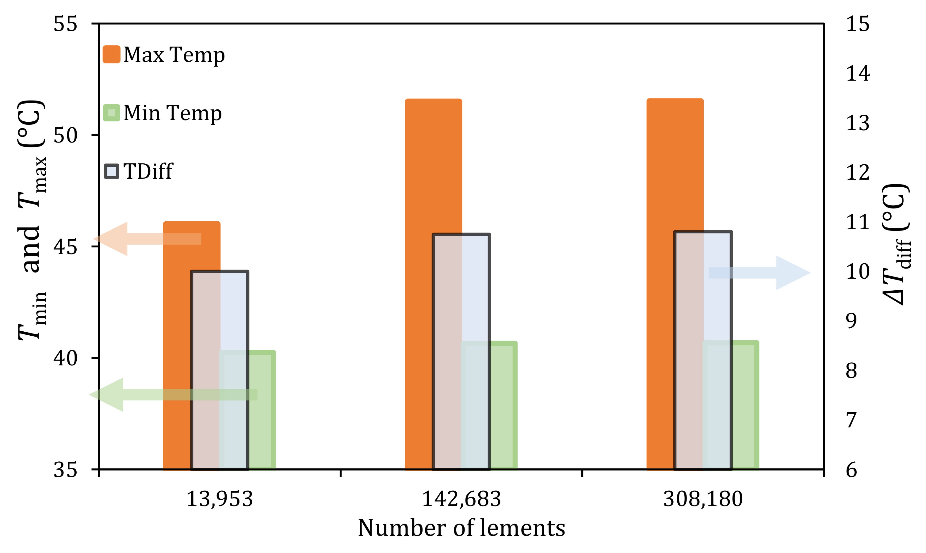
In order to solve this complex problem and geometry, the LIB module was meshed within Ansys-Fluent® tool. A mesh convergence analysis was performed. The number of elements used in the mesh was reduced from a highly refined mesh to a coarse one until no effect on the solution stability, accuracy and convergence was achieved. As such, the optimised mesh helped gain computational time efficiency for the same result accuracy. To ensure the mesh convergence was correct, the temperature values and gradients across the LIB module were monitored for the solution consistency. The mesh convergence study was applied to the air-cooling system, with the results illustrated in Figure 3 to show the effects of the number of mesh elements on the domain temperature. A hexahedral meshing type is used for the convenience of mapping our rectangular fluid and solid domains. Hexahedral elements are economical, i.e., tend to be more efficient for the same number of nodes compared to the tetrahedral and polyhedral ones [29].
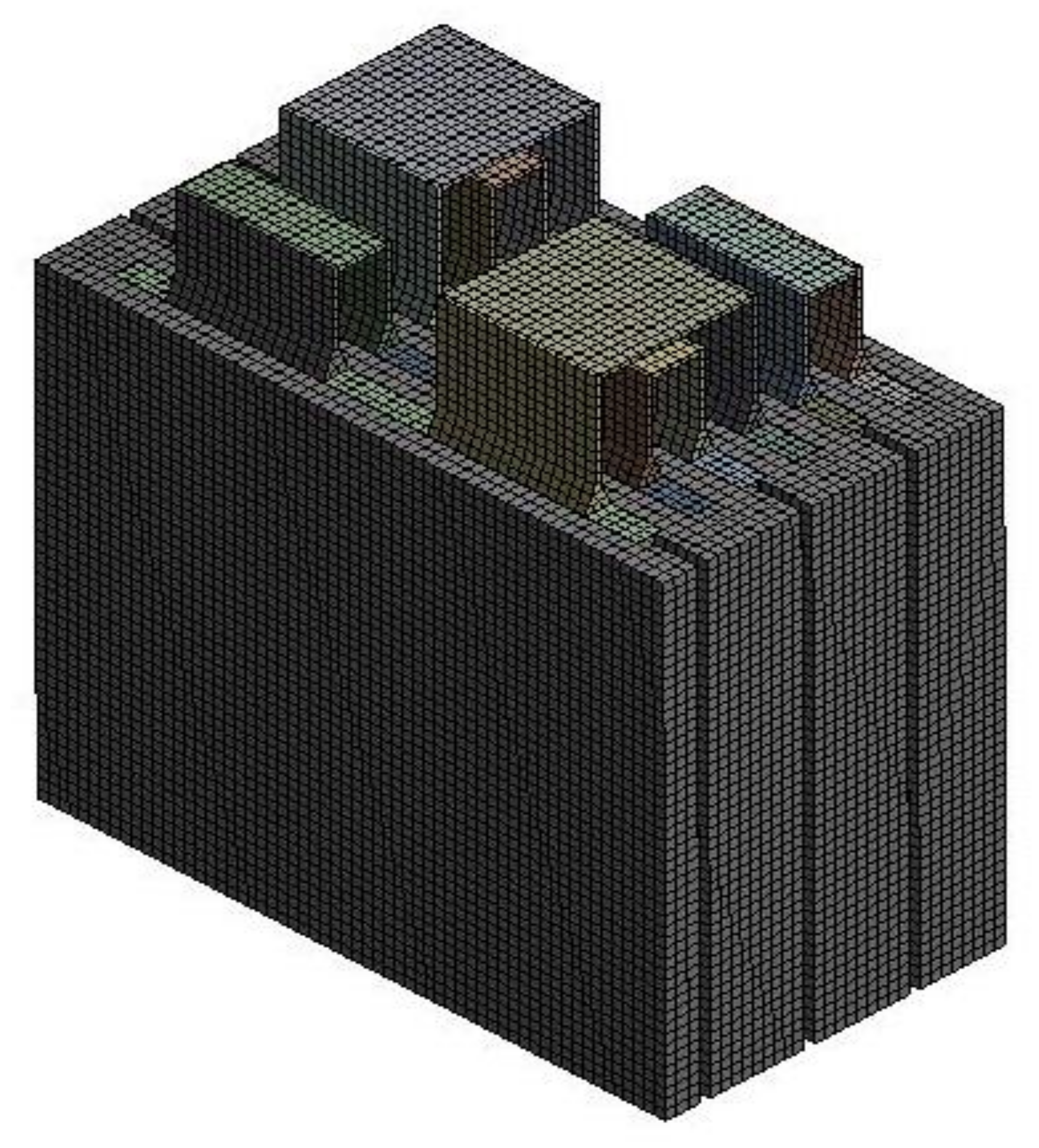
This convergence study clearly demonstrated the effects of the mesh on the results. As the number of elements were increased, the results consistency reveals a sufficient mesh independence check in Figure 3. Any further attempt to decrease mesh size would mean more unnecessary computational power was needed, increasing the run time of each simulation. Between a mesh size of 2 and 1.5 mm, there was a negligible difference in the three results. Consequently, a mesh size of 2 mm was chosen that has high accuracy based on the results. The final meshed model is depicted in Figure 4. This mesh consists of hexahedral elements with an element size of 2 mm with 142,683 elements that make up the complete BTMS ready for the simulations.

2.4. Biodiesel and Conventional Coolants

Four biodiesels were analysed and compared to each other to select the best cooling performance in BTMS. Two conventional coolants, air and 3M Novec 7100 were also simulated in conjunction with the biodiesel cooling. This approach has created a sensible comparison and allowed the effectiveness of the biodiesel to be assessed alongside most common mediums. Four dielectric fatty acid methyl ester (FAME) biodiesels were investigated for BTMS, namely palm, jatropha, mahua, and karanja.
Biodiesels are a form of alternative fuels that are made from natural substances, such as oils, animal fats, and plants [30]. These fuels are more economically friendly when compared with fossil fuels making it a better alternative in HEV where the aim is lowering exhaust gas emissions [30]. Palm oil biodiesel is a type of fuel made from a vegetable oil collected from palm trees. The fuel is created using methanol as a catalyst [30]. The fuel can be used directly in engines or can be mixed with diesel to produce different blends as outlined by [30]. The density of biodiesel is around 865 kg/m3 [31,32], making it relatively lighter than conventional LIB coolants, such as 3M Novec (1510 kg/m3 [33]) (see Table 3). The coolant mass reduction is necessary for the overall vehicle lightweight [34]. Jatropha is a type of plant which produces seeds with an oil content of around 37% [35], and mahua biodiesel is extracted from the mahua seed. Karanja oil, which can be extracted from the karanja tree, has both good diesel replacement features [35] and the feasibility of use as coolant. In [36], the effects of different blends of these four biodiesel fuels on their thermodynamic properties were investigated experimentally.
Air can be used to cool LIB at a cold ambient temperature via forced convection, where the fluid comes into direct contact with the LIB cells [18]. Air does not require indirect cooling, making it the easiest form of cooling as well as being the cheapest and best option for ease of maintenance. However, due to the low heat capacity of air, the system is very inefficient, as specified by [39]. Some studies, such as [40], have developed methods of increasing efficiency by adding fins or by optimising the fan speed to ensure maximum cooling is achieved. As such, an increase in fan power is needed to overcome the higher-pressure drop, which is not ideal in a HEV. Nevertheless, air-cooling can be the least effective approach due to its low thermodynamic properties, specifically density, thermal conductivity, and specific heat [23]. To increase the cooling efficiency, effective liquid coolants are required, which lead to higher density, added weight to the vehicle, and higher pumping power consumption.
3M Novec is used as coolant in many electronic applications, such as computer processors. In recent years, 3M Novec has been used in the direct cooling of BTMS due to its dielectric nature and excellent fire inhabitant [41]. On the other hand, the disadvantage of using 3M Novec in H/EV is its high density (see key fluid properties in Table 3). The 3M Novec properties are inferred from [33], while the properties of biodiesel fuels are inferred from [31,32].
The immersed 3M Novec BTMS is associated with several drawbacks, such as low cooling performance and maintenance issues [42]. In alternative approach, the circulation of 3M Novec through the system requires high pumping power and more storage of this dense fluid. Hence, exhausting the benefits of this BTMS. To maintain lightweight HEV and embed renewable factors in the system, biodiesels are our new concept of coolant in this study. In our study, all properties of coolants are assumed constant at 20 °C.

3. Results

In our study, LIB module was first simulated at different discharge rates without any form of cooling to be used as the benchmark data. The benchmark cooling data are compared with the cases of using air, 3M Novec, and biodiesels as coolants to analyse their thermal performance. A parametric study was conducted to investigate the relationship between biodiesel cooling performance and inlet velocity.
It is clear that the analytical solution can reflect a fully laminar flow, but turbulence can be caused in U-turns and with the thermal energy interactions. In the CFD analysis, the turbulent flow was taken into account within the hydraulic and thermal boundary layers. The κε turbulence model was used to accurately represent the turbulent nature of the flow in some regions whilst reducing computational time. Energy equations were enabled to allow for heat transfer in the system. It was assumed that radiation acting on the system was negligible. Furthermore, the following assumptions were made within the CFD workflow:
  • Transient flow;
  • Transient LIB electrochemistry;
  • Uniform inlet velocity;
  • Negligible radiative effect;
  • Incompressible flow; and
  • Viscous flow.
As air is the least effective at lower velocities, the inlet air velocity was tested in an extended range of 0.5–3 m/s to improve the convective heat transfer, as will be outlined in Section 3. For liquids (3M Novec and biodiesel fuels) cooling, the velocity was set to the range 0.09–0.5 m/s and initial temperature to 27 °C.

3.1. LIB without Cooling

The LIB module was simulated at four discharge rates of 0.5C, 1C, 3C, and 5C. The temperature distribution of the LIB module is shown in Figure 5. It can be seen that the temperature homogeneity across the LIB module was affected by increasing the discharge rate. At 0.5C, LIB cells 1 and 4 had the lowest temperature, with 0.007 °C maximum temperature difference between LIB cells. However, at 1C and 3C, the temperature difference between LIB cells was increased by 1.222 °C. The effect of discharge rates on the module temperature is illustrated in Figure 6.
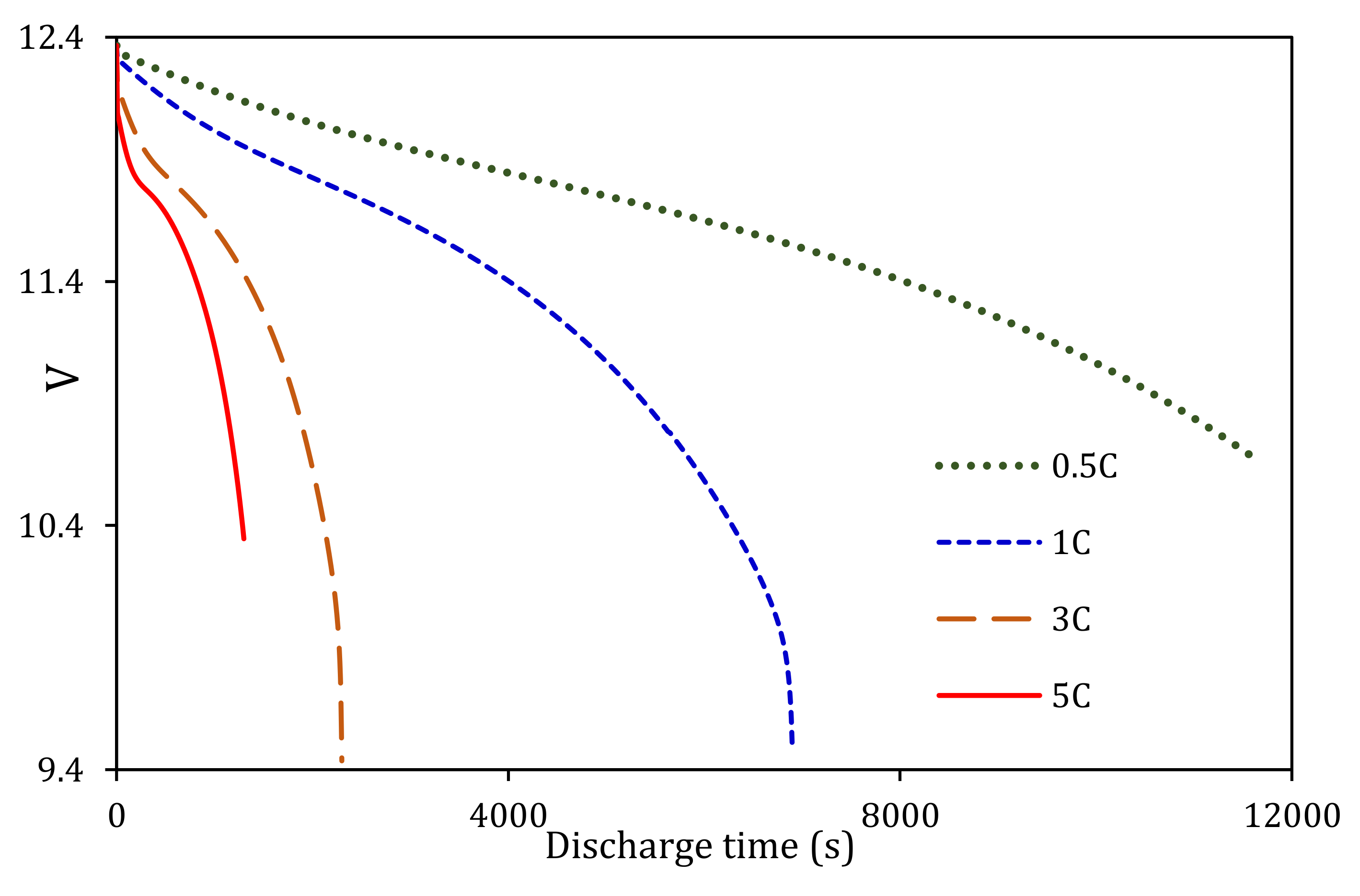
In Figure 6, one can see that the LIB module temperature increased with the higher discharge rates almost linearly. This LIB module required 11,630 s to reach a maximum temperature of 41.8 °C for a discharge rate of 0.5C. At 1C, the LIB module required 6890 s to reach the maximum temperature of 60.5 °C. This temperature was 42% higher than the LIB maximum operating temperature of 35 °C [9]. At a higher LIB module discharge rate (3C), the module has already exceeded its maximum temperature, reaching 101.6 °C, and at a much faster rate within 2300 s. At 5C, the battery was completely discharged within a shortened charge-state life of 1300 s, reaching 124.5 °C. Similarly, the maximum cell voltage has reduced due to the increase in temperature, as shown in Figure 7. The cell voltage trend is comparable to that reported in [33].
As can be seen from the results, the LIB module performance deteriorates at higher discharge rates without cooling. Based on the module temperature distribution, maximum temperature, fast discharge rates, and the temperature rise rate, it is imperative to implement effective BTMS solutions, particularly when operating at high discharge rates. Hence, we have focused our cooled BTMS results on the 3C for revealing the most common peak features of the system.

3.2. Air Cooling

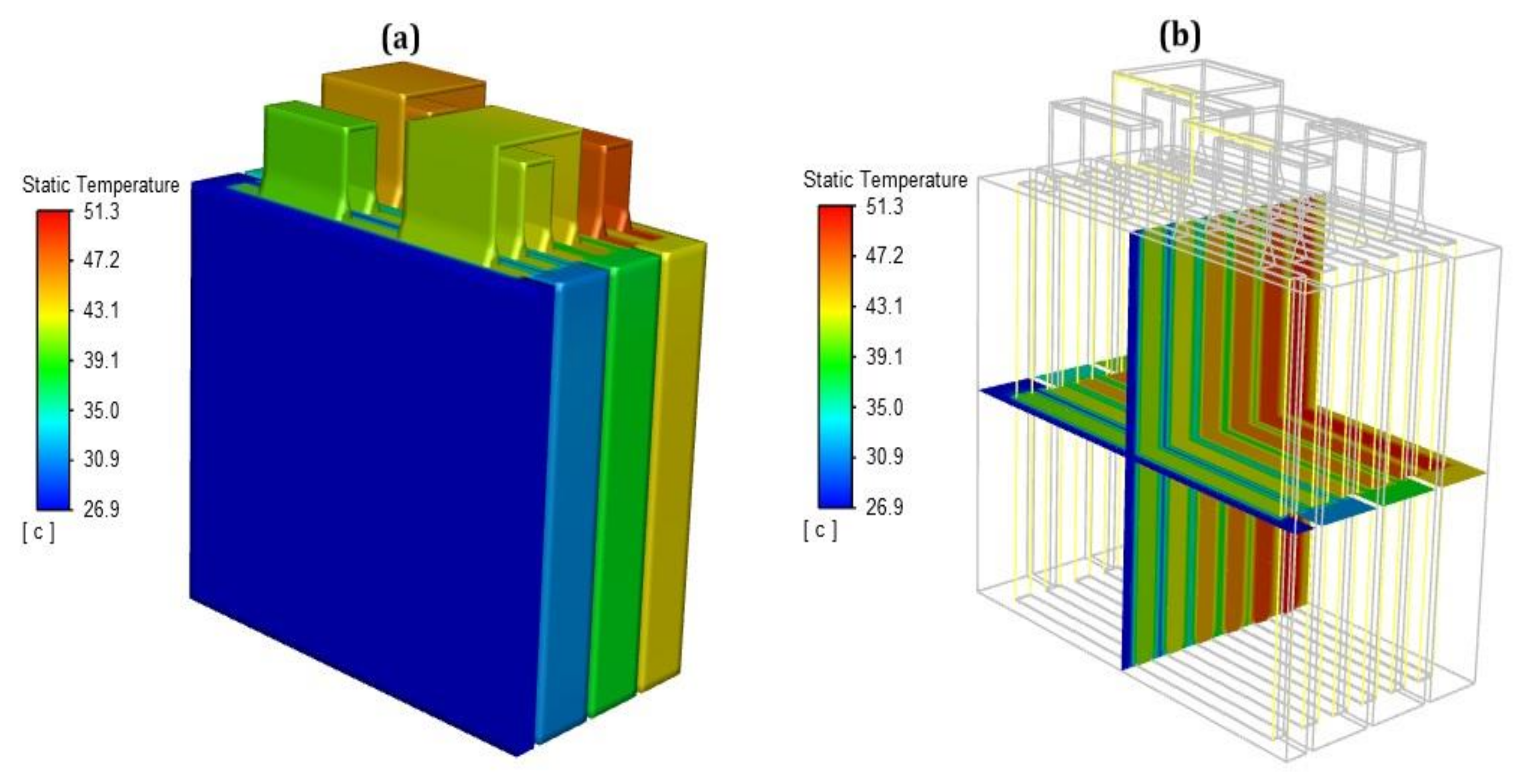
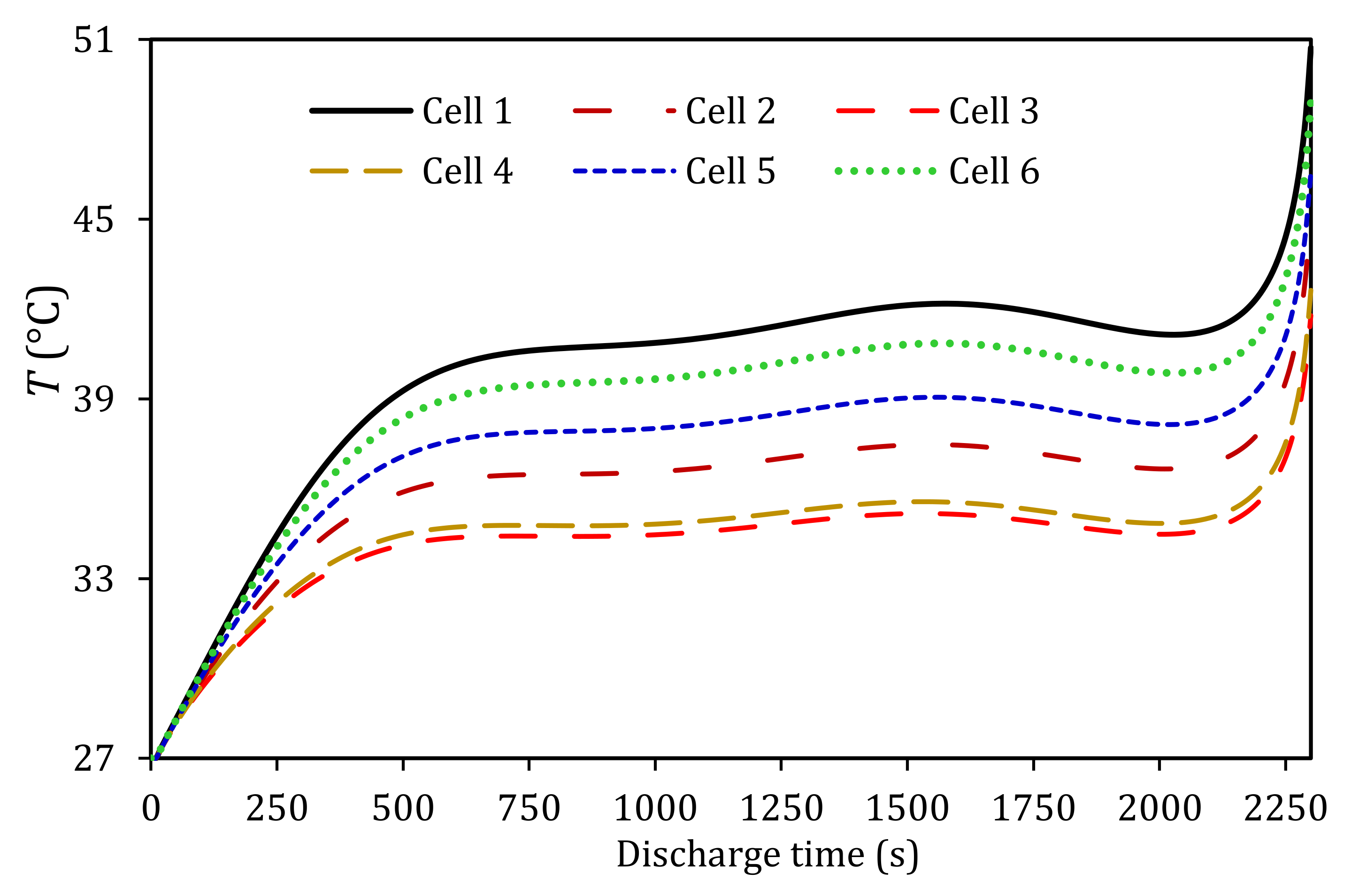
Air-cooling is the least efficient when compared to other cooling methods. The LIB module temperature distribution using air-cooling is illustrated in Figure 8. That is at a discharge rate of 3C and inlet velocity of 3 m/s. Air-cooling has significantly reduced the LIB module maximum temperature by 50% compared to no cooling temperature (see Figure 9). However, the air-cooling at 3 m/s inlet velocity was not effective for maintaining the LIB module temperature below the LIB maximum operating temperature. This was due to the low density and specific heat of air, which reduced the convective heat transfer.
In terms of LIB temperature homogeneity, the results showed a 10 °C difference between LIB cells, which can significantly reduce the LIB voltage balancing capability and promote faster cell degradation. The air temperature towards the outlet has a large increased temperature, which suggested that air was not as efficient at removing heat from the LIB module and thus needed a higher velocity.
Air-cooling caused a large temperature difference between LIB cell 1 and cell 6. However, that managed to keep all LIB cell temperatures in stable conditions for most of the discharge time. In addition, the air-cooling kept the temperature of LIB cells 1–4 below the maximum operating temperature. After 2200 s, all LIB cell temperatures started to increase due to higher internal resistance at a low state-of-charge (SOC), where the LIB cell 6 temperature has the highest value of 51.3 °C. These thermal behaviours indicated that air-cooling could be used as a cheaper alternative in applications where LIB does not require full discharge and hence does not reach beyond the maximum operating temperature. The high-temperature difference between LIB cells will require improvement in the air-cooling by adding fins and hot plates.

3.3. 3M Novec Cooling

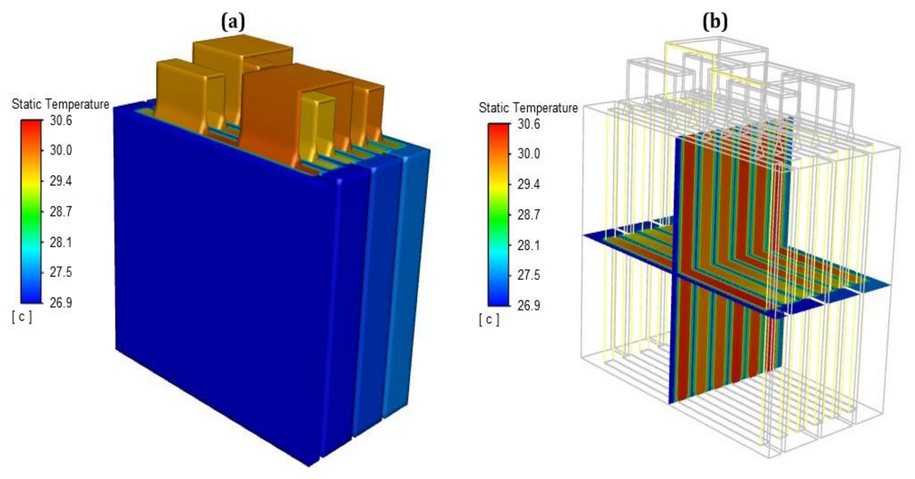
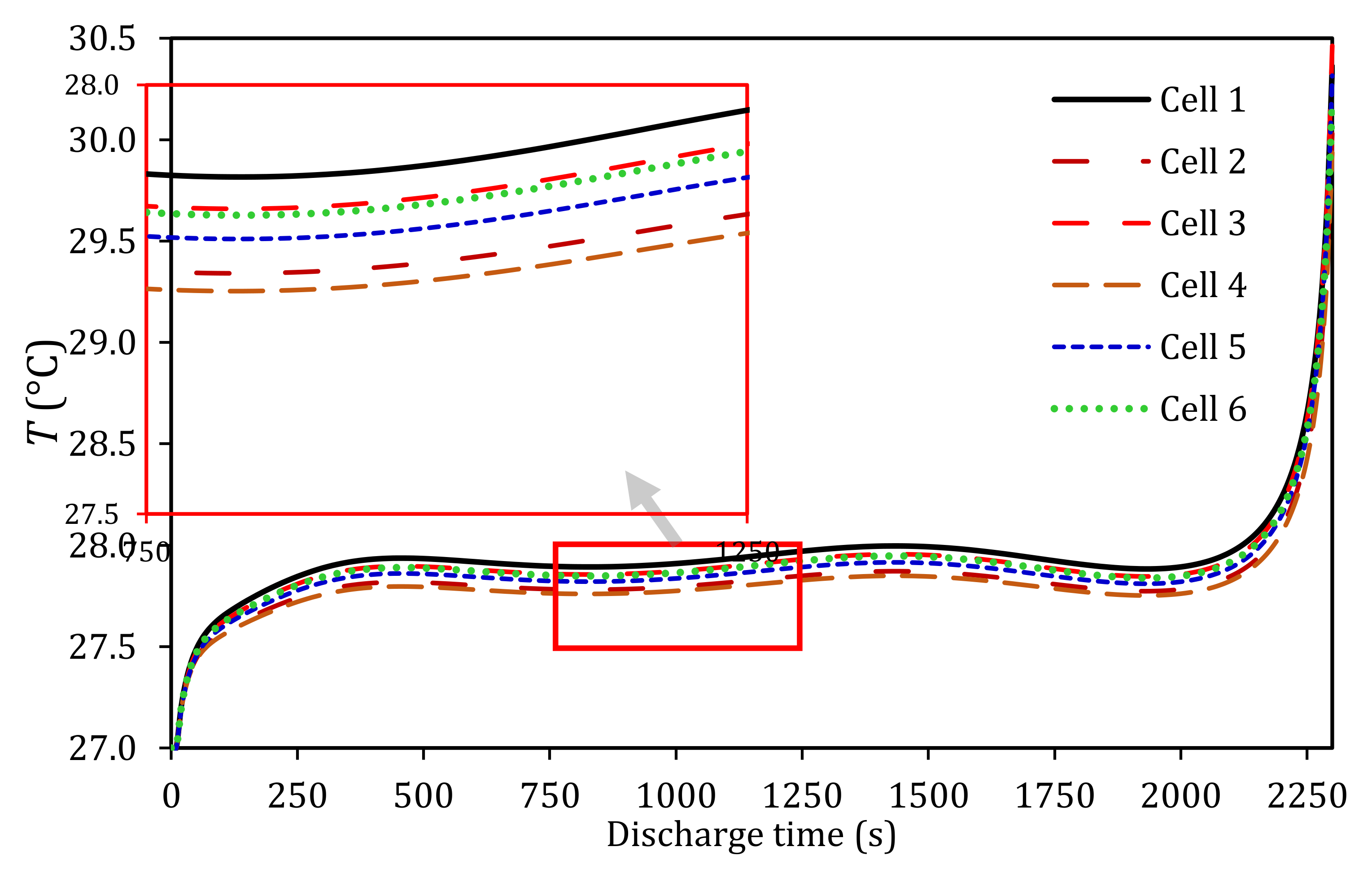
The temperature distribution of the LIB module based on 3M Novec cooling is shown in Figure 10. The 3M Novec cooling managed to reduce the LIB module maximum temperature to 30.6 °C, which was 70% lower than the benchmark maximum temperature. The temperature difference in each LIB cell was also kept below 1 °C (see Figure 11). The LIB module maximum temperature reduction in 3M Novec cooling suggested that it could provide a better solution compared to the air-cooling method at a reduced working fluid velocity. However, the high specific density of 3M Novec fluid (1.4–1.8 kg/m3 [43]) increases the overall vehicle weight, demands a higher pumping power, and adds up the requirement for a closed-loop storage tank.
The temperature behaviour at full depletion of each LIB cell is shown in Figure 11. 3M Novec cooling was able to maintain the temperature of all LIB cells below 28 °C for 2000 s. Additionally, 3M Novec cooling was able to characterise the LIB cells’ temperature in a fast response. Therefore, the pump can control 3M Novec fluid constantly and require less pumping energy. After 2000 s, it started to increase sharply to a maximum temperature of 30.35 °C due to the high LIB cell internal resistance at a lower SOC. Based on the LIB thermal behaviour using 3M Novec cooling, it is possible to let the LIB cell temperature rise in free convection environment until it reaches a certain temperature limit. Subsequently, a control system can start to pump 3M Novec fluid through the cooling system to keep the LIB cell temperature below the maximum operating temperature.

3.4. Biodiesel Cooling

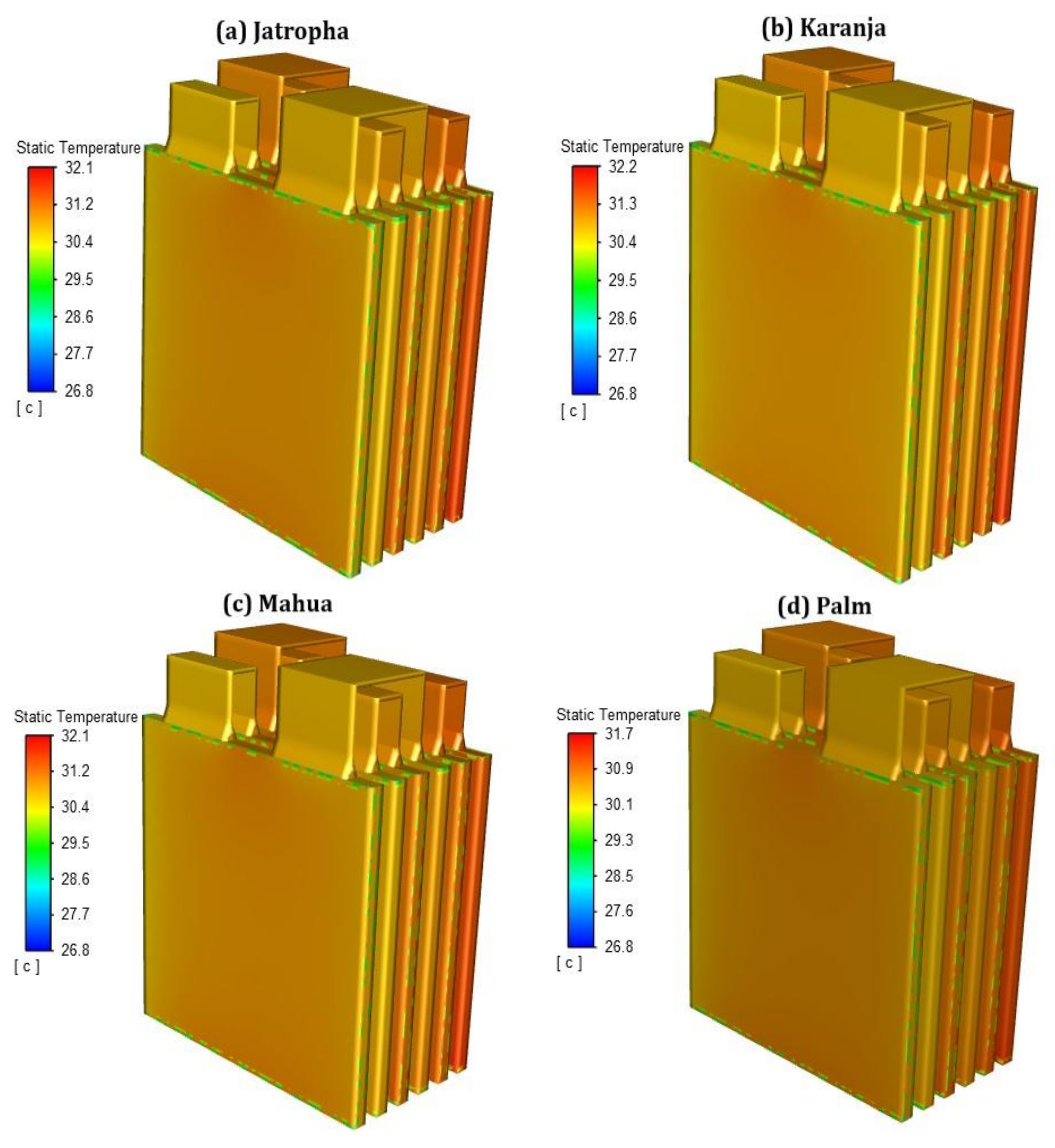
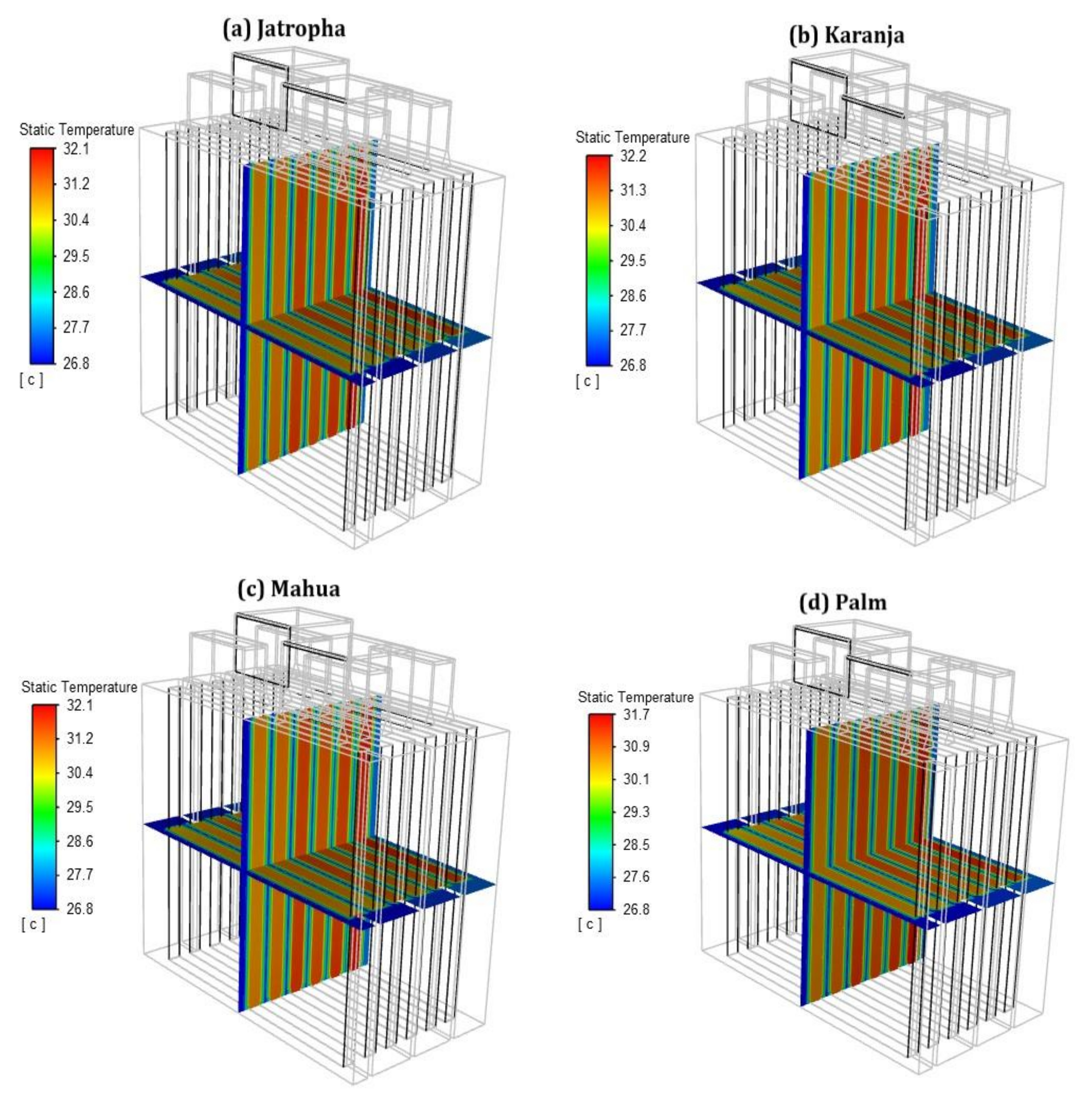
This section is investigating a new cooling method when using biodiesel as a coolant. The cell temperature distribution due to using various biodiesel fuels is shown in Figure 12. It is clear from the figure that the use of biodiesel as a coolant was effective in BTMS with the maximum temperature of all the simulations being below 32 °C after the LIB was fully discharged. As discussed before (see Section 1), the reduced LIB module’s temperature characteristics can help improve their performance, cell capacity, and minimise material degradation. Palm oil was the marginal effective cooling medium based on having the lowest maximum temperature (<2.6%) compared to the other three biodiesels.
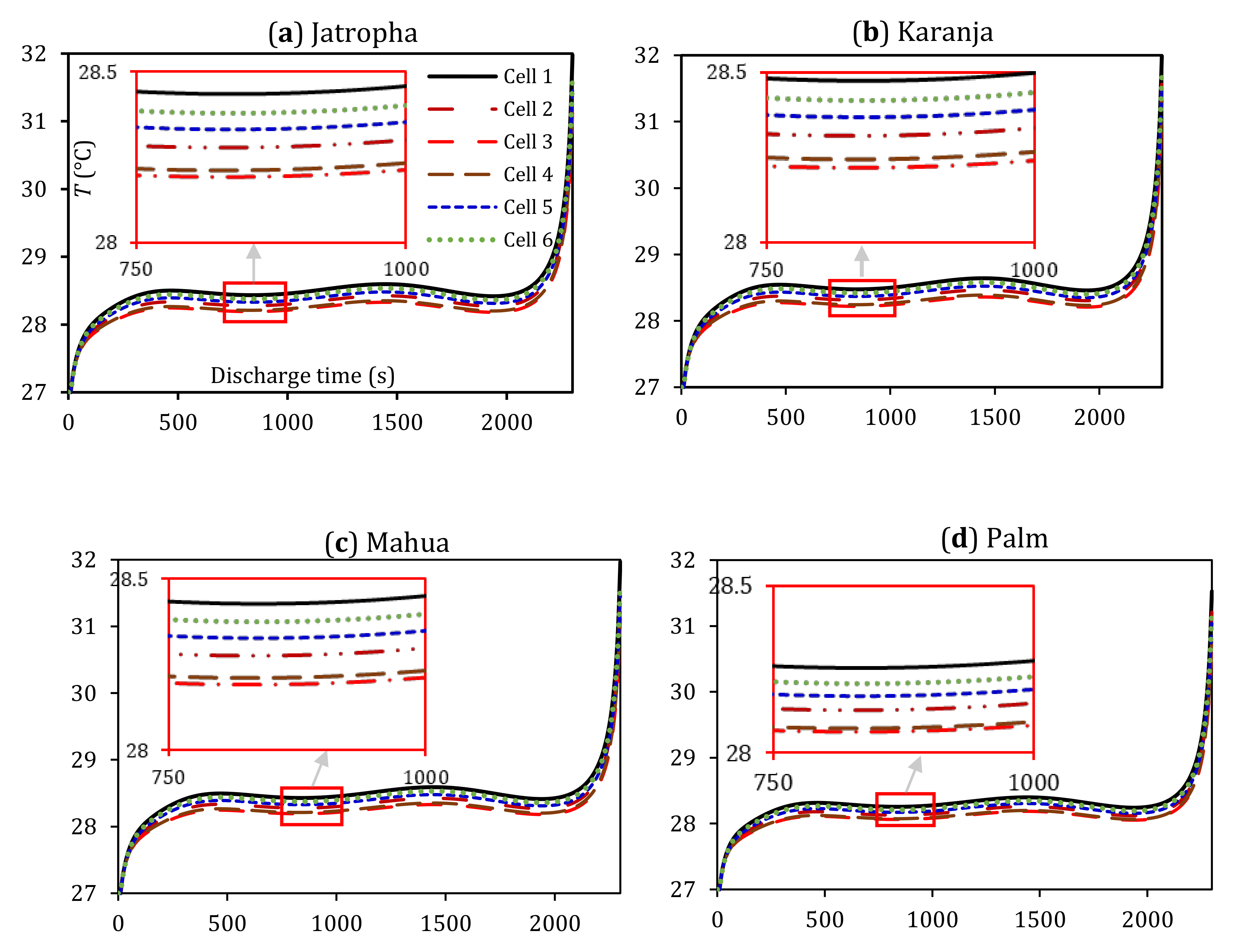
The cross-section temperature distribution across the LIB cells is illustrated in Figure 13. It can be observed that all biodiesels produced an evenly distributed temperature with up to 1 °C maximum difference across all cells. LIB cell 6 has the highest temperature due to the flow direction of the coolant that carried the heat from previous LIB cells. This issue was improved by having another inlet that runs the coolant in the opposite direction so that all the cells get the maximum heat transfer. However, a double inlet system would require extra pumping power and is not necessary for this particular LIB cell configuration. A larger LIB module with more cells would require a revision in enclosure geometry or an increase in velocity based on these results. The LIB temperatures for each cell versus the module total discharge time are illustrated in Figure 14. These have been simulated for each of the four proposed biodiesel oils of jatropha, karanja, mahua, and palm fatty acid methyl esters.
As one can see from Figure 14, there similar trends to those using the 3M Novec as coolant, where biodiesel cooling is able to reserve the temperature up to 28.5 °C for the first 2000 s of discharge time. The results further support our perdition that palm is, relatively, the best out of the four biodiesel types in reducing the LIB module temperature. With palm also being the least dense coolant, it would decrease the overall vehicle weight and extra space is formed. This is because the biodiesel is already stored in the vehicle meaning a separate storage tank is not required for the coolant.

3.5. Comparison among Modules

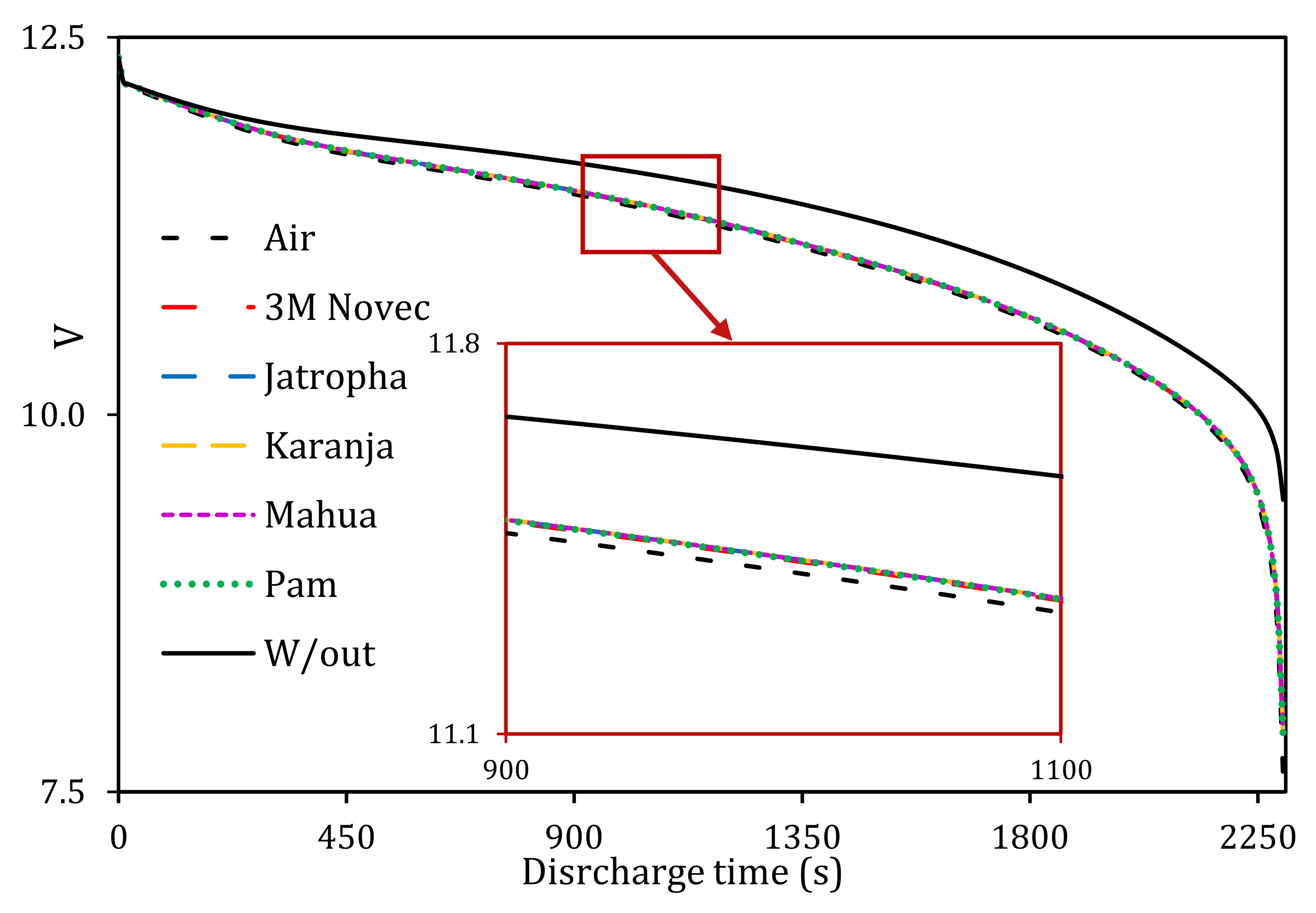
A comparison among air, 3M Novec, and biodiesel cooling methods has revealed the effectiveness of biodiesels in line with the commonly used BTMS coolants in industry. To verify the impacts of cooling temperature on the generated voltage, the module voltage is investigated for the full discharge evolutions of all cases at 3C, as shown in Figure 15. As can be seen from this figure, the voltage is almost identical in all cases, except for air with a noticeable variation in voltage at 3C. For instance, the battery without cooling was giving up to 24% more voltage compared to the evolution of the battery cooled with air for the same discharge rate, i.e., more power loss without cooling. It is expected that this loss will increase at higher discharge rates. The impacts of higher C-rates on temperature and voltage were illustrated in Figure 6 and Figure 7, respectively, for the LIB without cooling.
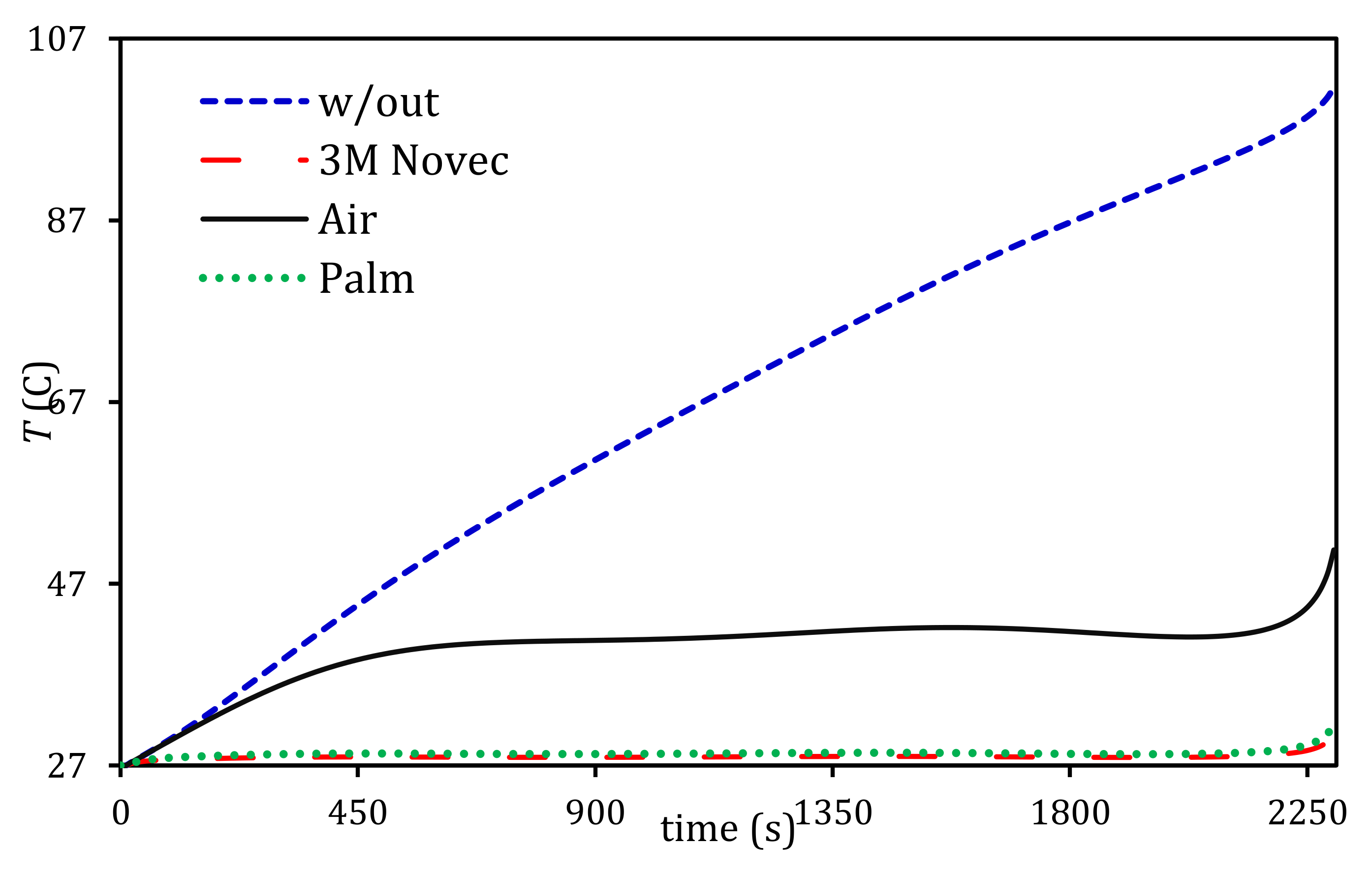
The maximum cell temperatures versus discharge time are evaluated for the case of biodiesel among the other three cases, including the case without cooling, as shown in Figure 16. The results show that all cooling techniques used were more effective in reducing the maximum temperature than the benchmark results (i.e., without cooling). However, air-cooling did not sufficiently reduce the temperature of the LIB module, indicating that there is still an undesirable maximum temperature that would minimise the system performance. The inefficient air-cooling is attributed to the relatively low thermodynamic properties of air, such as thermal conductivity, specific heat capacity, and density.
As can be seen from Figure 16, 3M Novec cooling provided the lowest LIB module temperature throughout the discharge cycle; however, that came at the expense of higher pumping power consumption (i.e., lower system exergy). Nevertheless, in comparison with biodiesel cooling (using palm oil FAME), there has not been a significant difference in terms of cooling performance, as both cooling strategies can maintain the LIB module temperature with the optimum operating temperature during the discharge cycle. One can see that, compared to 3M Novec cooling, using palm oil as a coolant is sufficient to compensate for the slight losses in cooling efficiency through the positive aspects of weight reduction.

4. Conclusions

The LIB module was successfully analysed using a commercial CFD software Ansys-Fluent to characterise the biodiesel in BTMS application. Four biodiesels, namely palm, jatropha, mahua, and karanja, were analysed and compared to more conventional coolants, such as air and 3M Novec. These comparison studies allowed for the evaluation of the effectiveness of biodiesel as a coolant in hybrid electric vehicle (HEV) battery thermal management systems (BTMS). An evaluation has been made to determine the relationship between LIB temperature parameters and cooling inlet velocity. The key conclusions from the studies are that:
  • A benchmark LIB module without any means of cooling exceeded the maximum working temperature with the temperature increased linearly at different discharge rates. At a lower discharge rate of 0.5C, the LIB module temperature exceeded the maximum working temperature by 5 °C when fully depleted. As the discharge rate increased to 3C, the LIB module temperature reached 140 °C, which can cause thermal runaway. In addition, the change in discharge rate affected the distribution of temperature across the LIB module. These results can significantly accelerate the LIB cells capacity degradation and performance, which are in need of an efficient BTMS to control the LIB module within the optimum operating temperature range.
  • Biodiesel cooling proved to be a very effective solution for BTMS with all the biodiesels being able to maintain the temperature within the optimum operating temperature range. The best biodiesel out of the four used was palm, as it managed to reduce the LIB module maximum temperature to 31.7 °C at a discharge rate of 3C, ensuring the LIB cells are working to their full potential and maintaining their lifespan. In addition, the low density of palm oil biodiesel (865 kg/m3) decreases the overall weight of the vehicle and the enclosure itself.
  • Air-cooling is an inefficient method, which was not able to maintain the LIB module temperature below the optimum range. In addition, the temperature gradient of the LIB module was 10 °C, creating the issue of uneven cell voltage and leading to faster LIB cell degradation. When compared with air-cooling, biodiesel is a much better approach in terms of cooling efficiency and power efficiency from the fluid source as air requires higher velocities to improve cooling.
  • 3M Novec performed the best out of the coolants in terms of maintaining the LIB optimum operating temperature. It was noted that 3M Novec maintained the LIB module temperature gradient at a desired temperature range. However, it is heavy, thus increasing the overall vehicle energy consumption, and it is expensive, in addition to its requirement for a complex system installation.
  • Biodiesel is seen as a good alternative coolant to save weight, improve the BTMS, and being renewable. For instance, using palm oil in a typical HEV can reduce the weight of the filled enclosure by up to 43%. This light-weighting can be a big advantage for improving system performance and fuel economy.

Author Contributions

Conceptualization, M.A.Q.; Data curation, H.S.S. and R.M.R.A.S.; Investigation, A.M.; Project administration, M.A.Q.; Resources, M.A.Q. and R.M.R.A.S.; Software, M.A.Q., A.M. and A.A.; Supervision, M.A.Q.; Validation, M.A.-D.; Visualization, Z.K. and H.S.S.; Writing—original draft, A.M., M.A.Q.; Writing—review & editing, M.A.Q., M.A.-D., Z.K., H.S.S. and R.M.R.A.S. All authors have read and agreed to the published version of the manuscript.

Funding

This research received no external funding.

Conflicts of Interest

The authors declare no conflict of interest.

References

  1. Hansen, T.A. Stranded Assets and Reduced Profits: Analyzing the Economic Underpinnings of the Fossil Fuel Industry’s Resistance to Climate Stabilization. Renew. Sustain. Energy Rev. 2022, 158, 112144. [Google Scholar] [CrossRef]
  2. Monasterolo, I.; Raberto, M. The Impact of Phasing out Fossil Fuel Subsidies on the Low-Carbon Transition. Energy Policy 2019, 124, 355–370. [Google Scholar] [CrossRef]
  3. Renewable Energy—Resources, Challenges and Applications; Al Qubeissi, M.; El-Kharouf, A.; Serhad Soyhan, H. (Eds.) IntechOpen: London, UK, 2020; ISBN 978-1-78984-283-8. [Google Scholar]
  4. Biofuels—Challenges and Opportunities; Al Qubeissi, M. (Ed.) IntechOpen: London, UK, 2019; ISBN 978-1-78985-535-7. [Google Scholar]
  5. Al Qubeissi, M. Predictions of Droplet Heating and Evaporation: An Application to Biodiesel, Diesel, Gasoline and Blended Fuels. Appl. Therm. Eng. 2018, 136, 260–267. [Google Scholar] [CrossRef]
  6. Al Qubeissi, M.; Sazhin, S.S.; Elwardany, A.E. Modelling of Blended Diesel and Biodiesel Fuel Droplet Heating and Evaporation. Fuel 2017, 187, 349–355. [Google Scholar] [CrossRef]
  7. Kaliaperumal, M.; Dharanendrakumar, M.S.; Prasanna, S.; Abhishek, K.V.; Chidambaram, R.K.; Adams, S.; Zaghib, K.; Reddy, M.V. Cause and Mitigation of Lithium-Ion Battery Failure—A Review. Materials 2021, 14, 5676. [Google Scholar] [CrossRef]
  8. Allafi, W.; Uddin, K.; Zhang, C.; Mazuir Raja Ahsan Sha, R.; Marco, J. On-Line Scheme for Parameter Estimation of Nonlinear Lithium Ion Battery Equivalent Circuit Models Using the Simplified Refined Instrumental Variable Method for a Modified Wiener Continuous-Time Model. Appl. Energy 2017, 204, 497–508. [Google Scholar] [CrossRef]
  9. Ma, S.; Jiang, M.; Tao, P.; Song, C.; Wu, J.; Wang, J.; Deng, T.; Shang, W. Temperature Effect and Thermal Impact in Lithium-Ion Batteries: A Review. Prog. Nat. Sci. Mater. Int. 2018, 28, 653–666. [Google Scholar] [CrossRef]
  10. Chen, D.; Jiang, J.; Kim, G.-H.; Yang, C.; Pesaran, A. Comparison of Different Cooling Methods for Lithium Ion Battery Cells. Appl. Therm. Eng. 2016, 94, 846–854. [Google Scholar] [CrossRef] [Green Version]
  11. Pesaran, A.; Santhanagopalan, S.; Kim, G.H. Addressing the Impact of Temperature Extremes on Large Format Li-Ion Batteries for Vehicle Applications (Presentation); National Renewable Energy Lab. (NREL): Golden, CO, USA, 2013. [Google Scholar]
  12. Saw, L.H.; Tay, A.A.O.; Zhang, L.W. Thermal Management of Lithium-Ion Battery Pack with Liquid Cooling. In Proceedings of the 2015 31st Thermal Measurement, Modeling & Management Symposium (SEMI-THERM), San Jose, CA, USA, 15–19 March 2015; pp. 298–302. [Google Scholar]
  13. Kim, J.; Oh, J.; Lee, H. Review on Battery Thermal Management System for Electric Vehicles. Appl. Therm. Eng. 2019, 149, 192–212. [Google Scholar] [CrossRef]
  14. Mohammed, A.G.; Elfeky, K.E.; Wang, Q. Recent Advancement and Enhanced Battery Performance Using Phase Change Materials Based Hybrid Battery Thermal Management for Electric Vehicles. Renew. Sustain. Energy Rev. 2022, 154, 111759. [Google Scholar] [CrossRef]
  15. Bibin, C.; Vijayaram, M.; Suriya, V.; Ganesh, R.S.; Soundarraj, S. A Review on Thermal Issues in Li-Ion Battery and Recent Advancements in Battery Thermal Management System. Mater. Today Proc. 2020, 33, 116–128. [Google Scholar] [CrossRef]
  16. Wen, J.; Yu, Y.; Chen, C. A Review on Lithium-Ion Batteries Safety Issues: Existing Problems and Possible Solutions. Mater. Express 2012, 2, 197–212. [Google Scholar] [CrossRef]
  17. Troxler, Y.; Wu, B.; Marinescu, M.; Yufit, V.; Patel, Y.; Marquis, A.J.; Brandon, N.P.; Offer, G.J. The Effect of Thermal Gradients on the Performance of Lithium-Ion Batteries. J. Power Sources 2014, 247, 1018–1025. [Google Scholar] [CrossRef]
  18. Pesaran, A.A. Battery Thermal Management in EV and HEVs: Issues and Solutions. Battery Man 2001, 43, 34–49. [Google Scholar]
  19. Raja Shah, R.M.; Jardine, B. Thermal Management Unit and System. Patent 2018. Available online: https://data.epo.org/publication-server/document?iDocId=6599379&iFormat=0 (accessed on 5 July 2022).
  20. Battery Pack and Module Thermal Simulation Software|Ansys. Available online: https://www.ansys.com/en-gb/applications/battery/pack-and-module-thermal-management (accessed on 15 October 2022).
  21. Wegmann, S.; Rytka, C.; Diaz-Rodenas, M.; Werlen, V.; Schneeberger, C.; Ermanni, P.; Caglar, B.; Gomez, C.; Michaud, V. A Life Cycle Analysis of Novel Lightweight Composite Processes: Reducing the Environmental Footprint of Automotive Structures. J. Clean. Prod. 2022, 330, 129808. [Google Scholar] [CrossRef]
  22. Wang, Y.; Biswas, A.; Rodriguez, R.; Keshavarz-Motamed, Z.; Emadi, A. Hybrid Electric Vehicle Specific Engines: State-of-the-Art Review. Energy Rep. 2022, 8, 832–851. [Google Scholar] [CrossRef]
  23. Al Qubeissi, M.; Almshahy, A.; Mahmoud, A.; Al-Asadi, M.T.; Shah, R.M.R.A. Modelling of Battery Thermal Management: A New Concept of Cooling Using Fuel. Fuel 2022, 310, 122403. [Google Scholar] [CrossRef]
  24. Cao, W.; Zhao, C.; Wang, Y.; Dong, T.; Jiang, F. Thermal Modeling of Full-Size-Scale Cylindrical Battery Pack Cooled by Channeled Liquid Flow. Int. J. Heat Mass Transf. 2019, 138, 1178–1187. [Google Scholar] [CrossRef]
  25. Wang, H.; Tao, T.; Xu, J.; Shi, H.; Mei, X.; Gou, P. Thermal Performance of a Liquid-Immersed Battery Thermal Management System for Lithium-Ion Pouch Batteries. J. Energy Storage 2022, 46, 103835. [Google Scholar] [CrossRef]
  26. Ho, V.-T.; Chang, K.; Lee, S.W.; Kim, S.H. Transient Thermal Analysis of a Li-Ion Battery Module for Electric Cars Based on Various Cooling Fan Arrangements. Energies 2020, 13, 2387. [Google Scholar] [CrossRef]
  27. Lin, J.; Chu, H.N.; Monroe, C.W.; Howey, D.A. Anisotropic Thermal Characterisation of Large-Format Lithium-Ion Pouch Cells. Batter. Supercaps 2022, 5, e202100401. [Google Scholar] [CrossRef]
  28. Eastop, T.D.; McConkey, A. Applied Thermodynamics for Engineering Technologists, 5th ed.; Longman: London, UK, 1993; ISBN 9780582091931. [Google Scholar]
  29. Tu, J.; Yeoh, G.-H.; Liu, C. CFD Mesh Generation: A Practical Guideline. In Computational Fluid Dynamics; Elsevier: Amsterdam, The Netherlands, 2018; pp. 125–154. ISBN 978-0-08-101127-0. [Google Scholar]
  30. Yasin, M.H.M.; Mamat, R.; Sharma, K.; Yusop, A.F. Influence of Palm Methyl Ester (PME) as an Alternative Fuel in Multicylinder Diesel Engine. J. Mech. Eng. Sci. 2012, 3, 331–339. [Google Scholar] [CrossRef]
  31. Al Qubeissi, M.; Sazhin, S.S.; Crua, C.; Turner, J.; Heikal, M.R. Modelling of Biodiesel Fuel Droplet Heating and Evaporation: Effects of Fuel Composition. Fuel 2015, 154, 308–318. [Google Scholar] [CrossRef] [Green Version]
  32. Sazhin, S.S.; Al Qubeissi, M.; Kolodnytska, R.; Elwardany, A.E.; Nasiri, R.; Heikal, M.R. Modelling of Biodiesel Fuel Droplet Heating and Evaporation. Fuel 2014, 115, 559–572. [Google Scholar] [CrossRef] [Green Version]
  33. Lain, M.J.; Kendrick, E. Understanding the Limitations of Lithium Ion Batteries at High Rates. J. Power Sources 2021, 493, 229690. [Google Scholar] [CrossRef]
  34. Delogu, M.; Zanchi, L.; Dattilo, C.A.; Pierini, M. Innovative Composites and Hybrid Materials for Electric Vehicles Lightweight Design in a Sustainability Perspective. Mater. Today Commun. 2017, 13, 192–209. [Google Scholar] [CrossRef]
  35. Takase, M.; Zhao, T.; Zhang, M.; Chen, Y.; Liu, H.; Yang, L.; Wu, X. An Expatiate Review of Neem, Jatropha, Rubber and Karanja as Multipurpose Non-Edible Biodiesel Resources and Comparison of Their Fuel, Engine and Emission Properties. Renew. Sustain. Energy Rev. 2015, 43, 495–520. [Google Scholar] [CrossRef]
  36. Manjunath, M.; Prakash, P.; Raghavan, V.; Mehta, P.S. Composition Effects on Thermo-Physical Properties and Evaporation of Suspended Droplets of Biodiesel Fuels. SAE Int. J. Fuels Lubr. 2014, 7, 833–841. [Google Scholar] [CrossRef]
  37. Sirisomboon, P.; Posom, J. Thermal Properties of Jatropha Curcas L. Kernels. Biosyst. Eng. 2012, 113, 402–409. [Google Scholar] [CrossRef]
  38. Shadangi, K.P.; Mohanty, K. Comparison of Yield and Fuel Properties of Thermal and Catalytic Mahua Seed Pyrolytic Oil. Fuel 2014, 117, 372–380. [Google Scholar] [CrossRef]
  39. Huber, C.; Kuhn, R. Thermal Management of Batteries for Electric Vehicles. In Advances in Battery Technologies for Electric Vehicles; Elsevier: Amsterdam, The Netherlands, 2015; pp. 327–358. [Google Scholar]
  40. Teng, H. Thermal Analysis of a High-Power Lithium-Ion Battery System with Indirect Air Cooling. SAE Int. J. Altern. Powertrains 2012, 1, 79–88. [Google Scholar] [CrossRef]
  41. Zhao, J.; Xue, F.; Fu, Y.; Cheng, Y.; Yang, H.; Lu, S. A Comparative Study on the Thermal Runaway Inhibition of 18650 Lithium-Ion Batteries by Different Fire Extinguishing Agents. iScience 2021, 24, 102854. [Google Scholar] [CrossRef]
  42. Roe, C.; Feng, X.; White, G.; Li, R.; Wang, H.; Rui, X.; Li, C.; Zhang, F.; Null, V.; Parkes, M.; et al. Immersion Cooling for Lithium-Ion Batteries—A Review. J. Power Sources 2022, 525, 231094. [Google Scholar] [CrossRef]
  43. 3MTM NovecTM 7000 Engineered Fluid. Available online: https://www.3m.com/3M/en_US/company-us/SDS-search/ (accessed on 28 July 2021).
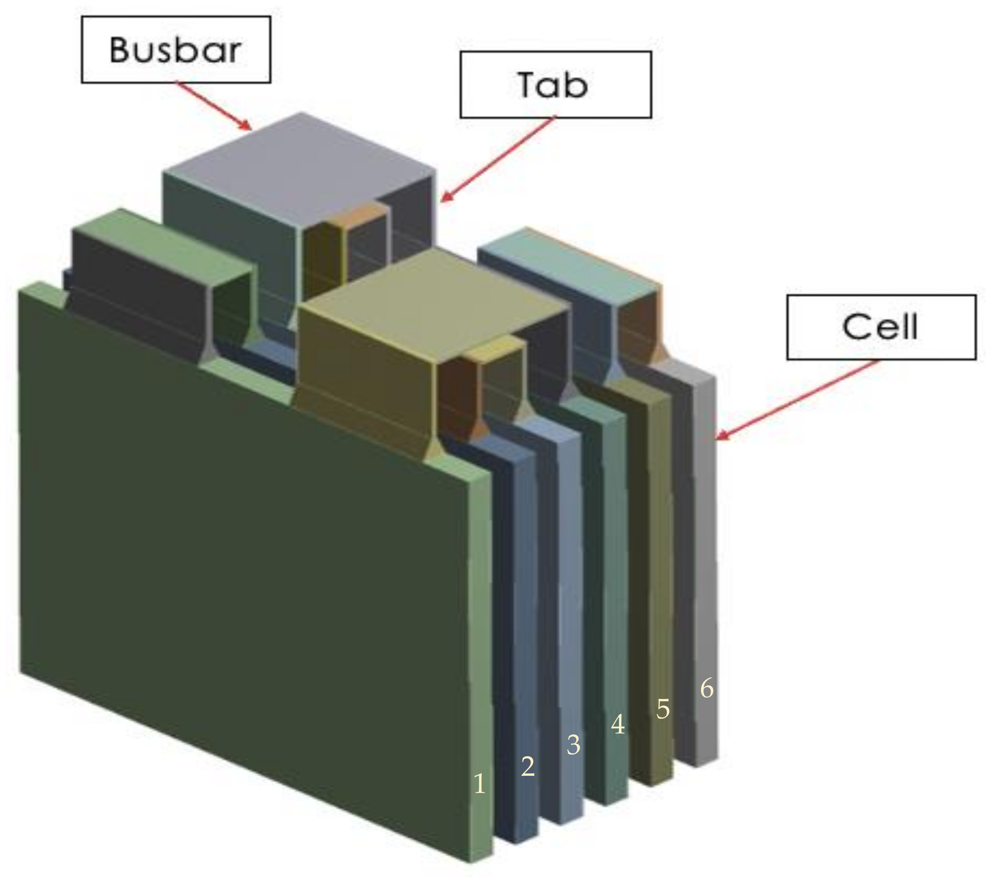
Figure 1. Schematic of the 3S2P LIB module, showing the six cells identified according to their position within the fluid domain, inlet (number 1) and outlet (number 6) cells.
Energies 16 00565 g001
Figure 2. Schematic of the 3S2P LIB enclosure geometry, showing (a) isometric view and (b) top view of the domains.
Energies 16 00565 g002
Figure 3. Temperatures across the battery cell and fluid domains versus number of elements, showing the maximum and minimum temperatures and temperature difference.
Energies 16 00565 g003
Figure 4. Final mesh of 3S2P LIB with enclosure, which consists of 142,683 hexahedral elements.
Energies 16 00565 g004
Figure 5. LIB module temperature distribution without cooling at discharge rate of (a) 0.5C, (b) 1C, (c) 3C, and (d) 5C.
Energies 16 00565 g005
Figure 6. LIB module (3S2P) temperature during full depletion at different discharge rates.
Energies 16 00565 g006
Figure 7. LIB voltage versus discharge time, showing the full module connected for 3S2P at 0.5C, 1C, 3C, and 5C discharge rates.
Energies 16 00565 g007
Figure 8. LIB module temperature characteristics at 3C discharge rates with air-cooling (a) temperature distribution and (b) cell cross-section temperature.
Energies 16 00565 g008
Figure 9. LIB cells temperature characteristic at 3C discharge rate with air-cooling.
Energies 16 00565 g009
Figure 10. LIB module temperature characteristics at 3C discharge rates with 3M Novec cooling, showing (a) full system temperature distribution and (b) cell cross-sectional temperature distribution.
Energies 16 00565 g010
Figure 11. LIB cells temperature characteristic at a 3C discharge rate with 3M Novec cooling.
Energies 16 00565 g011
Figure 12. LIB module temperature distribution at 3C discharge rates using the biodiesel fuel of (a) jatropha, (b) karanja, (c) mahua, and (d) palm oils.
Energies 16 00565 g012
Figure 13. LIB cell cross-sectional temperatures at 3C discharge rates, using the biodiesel oils of (a) jatropha, (b) karanj, (c) mahua, and (d) palm FAMEs.
Energies 16 00565 g013
Figure 14. LIB cells temperatures versus discharge time at 3C discharge rate, using biodiesel cooling, showing (a) jatropha, (b) karanja, (c) mahua, and (d) palm oil FAMEs as coolants.
Energies 16 00565 g014
Figure 15. LIB module voltage versus discharge time for all BTMS coolants at 3C.
Energies 16 00565 g015
Figure 16. LIB module temperatures versus time using different cooling strategies at a 3C discharge rate.
Energies 16 00565 g016
Table 1. LIB Module Component Material Properties.
PropertiesAluminium (Busbar)Copper (Tab)LIB Cell Material
Density (kg/m3)271989782029
Specific heat (J/kg · K)871381678
Thermal conductivity (W/m · K)202.4387.618.2
Electrical conductivity (s/m)3.541 × 1075.8 × 1075.8 × 107
Table 2. Specifications of LIB Cells Used in this Study.
Nominal Capacity (Ah)30
C-rates0.5–5
Maximum voltage (V)4.2
Minimum voltage (V)2.7
Height (mm)100
Width (mm)100
Thickness (mm)5
Table 3. Key Thermodynamic Properties of Cooling Fluids.
CoolantDensity (kg/m3)Viscosity (kg/ms)Thermal Conductivity (W/mK)Specific Heat (J/kg · K)
Palm [31,32]8653.91 × 10−30.1721687.248
Jatropha [37]8704.49 × 10−30.1661344.881
Mahua [38]8754.88 × 10−30.1701379.166
Karanja [31,32]8955.62 × 10−30.1721257.633
3M Novec 7100 [33]15106.0 × 10−40.0691183
Air1.2251.79 × 10−50.0251006.43
Disclaimer/Publisher’s Note: The statements, opinions and data contained in all publications are solely those of the individual author(s) and contributor(s) and not of MDPI and/or the editor(s). MDPI and/or the editor(s) disclaim responsibility for any injury to people or property resulting from any ideas, methods, instructions or products referred to in the content.