Article

Performance Study of Gravity-Type Heat Pipe Applied to Fuel Cell Heat Dissipation

College of Mechanical and Electrical Engineering, Qingdao University, Qingdao 266071, China
*
Author to whom correspondence should be addressed.
Energies 2023, 16(1), 563; https://doi.org/10.3390/en16010563
Submission received: 22 November 2022 / Revised: 17 December 2022 / Accepted: 29 December 2022 / Published: 3 January 2023

Abstract

:
A gravity-type heat pipe boiling characteristics test rig was constructed to solve the heat dissipation problem of fuel cells during operation. The boiling heat transfer characteristics of water in a parallel plate under negative pressure at different inclination angles and heat flow density input are investigated. The results show that: First, the gravity-type heat pipe can dissipate some heat and it is possible to use it for fuel cell heat dissipation. Second, with a certain range of heat flow density, the temperature of all parts of the plate is about 80 °C, with a small temperature difference, which is conducive to the safe operation of the fuel cell. Third, the heat flow density is in the range of 2222~3111 W·m−2, the temperature difference is large, and the outlet temperature is greater than 80 °C, which exceeds the operating temperature of the fuel cell, and the power-type heat pipe should be used for heat dissipation. Fourth, the average temperature of the plate placed at an inclination angle of 45°~60° is lower compared to other angles, and the temperature is evenly distributed. On the one hand, the conclusions reveal the characteristics of boiling heat exchange under negative pressure conditions of water inside the flat plate and, on the other hand, provide a reference for designing heat pipe systems for fuel cell heat dissipation.

1. Introduction

Fuel cells are efficient and clean new power generation technologies that will become an important power source in the future with the advantages of high efficiency and cleanliness and cyclic performance [1]. The opportunity to use fuel cells to store electric energy is very attractive, compared with charging from the charging pile, the charging time is shorter, and it is easier to travel long distances [2]. However, a problem has to be solved in fuel cells, and that is heat dissipation. There are a lot of problems caused by poor heat dissipation in practical applications, which makes heat dissipation a bottleneck that restricts the development of batteries. Traditionally single-phase thermal management systems via air or liquid cooling have been the standard for thermal management, but as cooling requirements increase, single-phase cooling is no longer sufficient to meet the necessary cooling needs [3], and an appropriate battery thermal management system is required to ensure the safe and efficient performance of the fuel cell.
Heat pipes are two-phase, highly efficient, and unique heat transfer elements [4], which rely on the absorption or release of latent heat when the gas–liquid phase change occurs in the fluid flowing inside them to achieve energy transfer, and have the advantages of large heat exchange and small heat transfer area. At a pressure of 1.7 kPa, the saturation temperature of water is only 15 °C [5]. Phase change heat absorption using phase change materials is widely used in battery heat dissipation techniques [6,7,8], which are capable of producing heat transfer coefficients of an order of magnitude or more using the sensible and latent heat transfer [9]. Improving the boiling heat transfer performance of the working mass in the evaporator is the key to increase the energy efficiency in industrial applications and is one of the techniques that researchers have focused on using [10].
Liu et al. [11] found the best heat transfer performance of CuO nanofluid heat pipes at an inclination angle of 45°. Kumaresan et al. [12] found that the thermal resistance of the heat pipe with CuO nanofluids as the medium would first increase and then decrease with the increase in the inclination angle of the heat pipe. When the inclination angle deviates 45 degrees, the thermal resistance will continue to increase. Therefore, the 45 degree heat pipe is the best inclination angle of the heat pipe. Therefore, we can use this as a reference to compare the following experimental results and analyze their differences. Jia Qiang et al. [13] showed that the number of heat pipes significantly affects the average temperature of the cell, with the cooling rate being the highest. Kumar et al. [14] described the flow patterns formed by multi-transfer heat in micro-channels or small channels and the parameters that affect the flow pattern transition. Hong et al. [15] pointed out the influence of heat flux on boiling heat transfer coefficient: Heat flux mainly affects the nuclear boiling heat transfer of pure fluid. Bortolin et al. [16] pointed out that when the heat flux increases, the heat transfer coefficient increases, the steam flow velocity increases, the heat exchange between gas–liquid and gas–solid is strengthened, and the heat exchange efficiency is improved. At this time, we can find the influence on the average temperature and heat transfer coefficient of the fuel cell under the conditions of different tilt angles and heat flux. Copetti et al. [17] studied the boiling heat transfer characteristics of R600A, and they found that the heat transfer coefficient increased with the increase in heat flux.
Although heating exchangers have been extensively studied, there are still many unknown factors. The new cooling method based on the principle of phase change shows great potential for application, so the application of heat pipes in the field of fuel cell heat dissipation is of huge significance. Therefore, this test is committed to analyzing and solving the heat dissipation problem of fuel cells, so that fuel cells can operate more safely. Through the test results, we can know that the gravity-type heat pipe can dissipate a certain amount of heat to the fuel cell, and the heat pipe will have different heat dissipation effects under different tilt angles. In this study, we built a stainless steel parallel plate test bench with water as the working medium to quantitatively study the temperature distribution of the working medium inside the plate with heat flux and the tilt angle of the plate for the problem of heat dissipation in fuel cells.

2. Test setup, Measurement Method, and Data Measurement

2.1. Test Setup

As can be observed from Figure 1, a large amount of heat is generated on both sides of the membrane electrodes during the operation of the proton exchange membrane fuel cell, and a cooling plate is added between the membrane electrodes for heat dissipation. The operating temperature is very important to the fuel cell system because it determines the performance and normal operation of the fuel cell system [18]. The following experimental object is a cooling plate, for which a series of conditions are varied to investigate the boiling heat transfer characteristics of water in a parallel plate under negative pressure and the change in temperature of the membrane electrode surface.
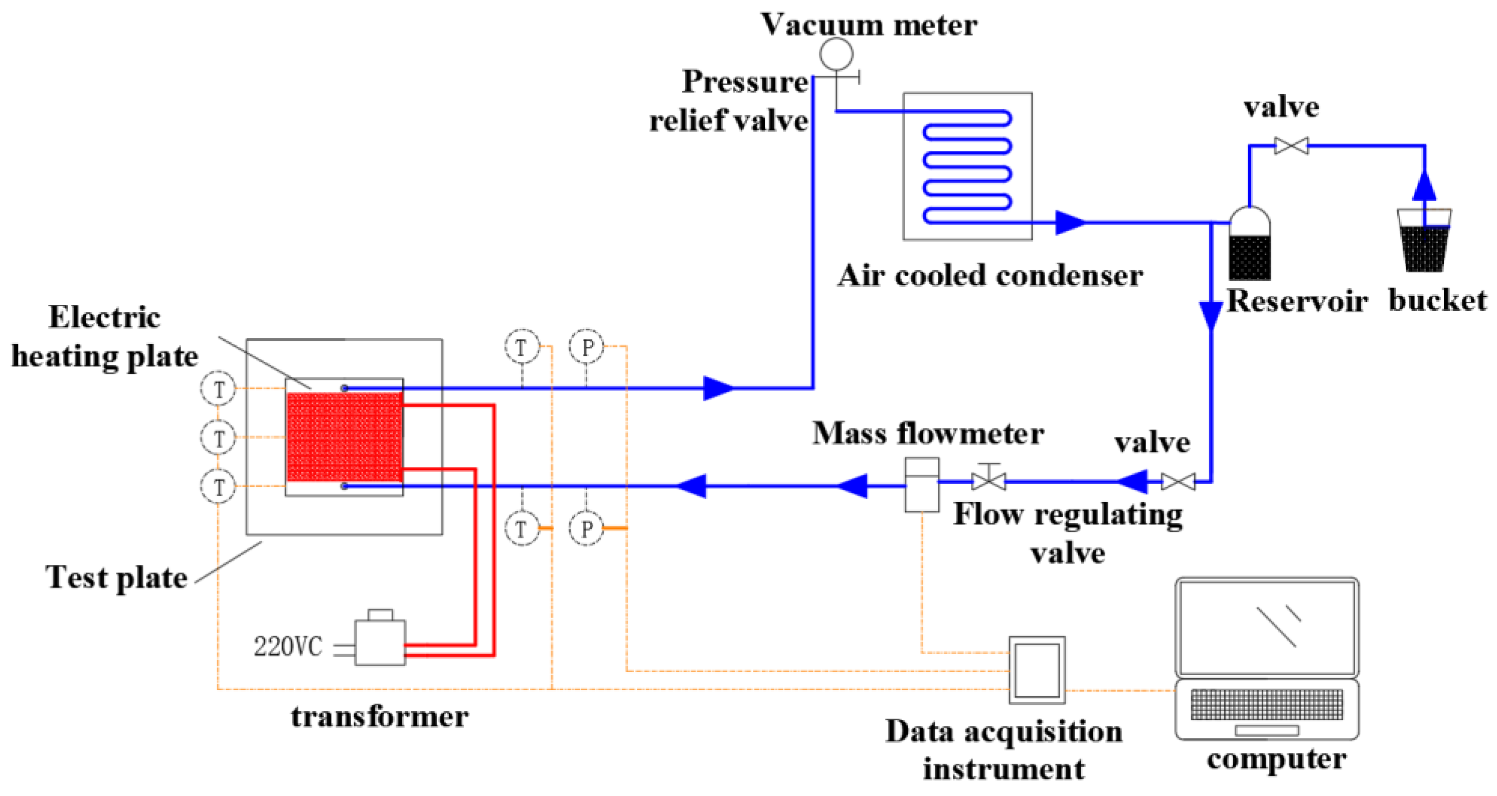
A gravity-type heat pipe boiling characteristics test bench was built, and the principle of the experimental setup is illustrated in Figure 2. The test bench consists of an electric heating system (regulator, electric heating plate), heat pipe circulation system (liquid storage tank, flow adjustment valve, mass flow meter, evaporator, air-cooled condenser), and data acquisition system (data acquisition instrument, temperature sensor, pressure sensor). The electric heating system controls the temperature of the silicone rubber electric heating plate by adjusting the power of the transformer. The heat pipe system is the main measurement object of the study. The cavity is 150 mm long, 150 mm wide, the inlet and outlet diameters are 10 mm, the gap between the two plates is 3 mm, and the wall is stainless steel and its thickness is 3 mm. The working medium in the plate is distilled water, and the heat exchange takes a bottom-in, top-out manner. The data acquisition system consists of two pressure sensors, five Pt1000 platinum resistance temperature sensors, a mass flow meter, and a data acquisition system to obtain experimental data such as temperature, pressure, and mass flow rate.
The process of circulating the working mass in the experimental device is as follows: First, the system is pumped to an approximate vacuum state of 1000 Pa. The valve at the outlet of the reservoir is opened and liquid distilled water enters the system from the reservoir, and the system is pumped again. The electric heating device is opened, heat from the silicon rubber electric heating plate is absorbed, boiling under the negative pressure conditions occurs, and a change from liquid evaporation to gas–liquid two-phase flow occurs. The generated gas–liquid two-phase flow flows out of the evaporator, and then flows upward into the air-cooled condenser for cooling. At this time, the gas–liquid two-phase flow is cooled into liquid water, and then the cooled liquid water returns to the liquid storage tank. Under the action of gravity, it enters the evaporator again to complete a cycle.
The flat plate is insulated by 30 mm asbestos and 30 mm insulation cotton in turn, and other connecting pipelines are insulated with thick 30 mm insulation cotton to reduce heat loss.
Figure 3 represents the arrangement scheme of temperature and pressure at each position of the evaporator. A pressure sensor is set on the inlet and outlet of the evaporator. Temperature measurement points are set at 0 mm, 75 mm, and 150 mm from the bottom of the test plate, and each temperature measurement point has one temperature sensor to measure the temperature of the outer wall surface of the plate. Five temperature measurement points from the inlet to the outlet are recorded as T1, T2, T3, T4, and T5, where T1 and T5 are distributed in the inlet and outlet, and T2, T3, and T4 are distributed on the flat plate.

2.2. Experimental Methods and Data Measurement

The experiment starts by keeping the system under negative pressure and without any change in pressure. When the system is stabilized, the temperature of each temperature measurement point is measured. After that, the electric heating unit is activated and the voltage is adjusted by adjusting the transformer to control the heat addition to the evaporation section and thus to control the heat flow density to the plate input. The flow meter used in the system is a model RHE14 mass flow meter manufactured by RHEONIK, consisting mainly of a transmitter, a receiver, and a special RHEONIK wiring cable. The flow meter allows measurement of the following fluid temperature range: −40~60 °C, mass flow rate range: 0~30 kg·min−1, accuracy level: ±0.2%. The measured experimental data are collected and recorded by the Agilent Bench Link Data Logger software used with the Agilent 34972A data acquisition instrument. The pressure sensor is a Siemens QBE2002-P20 pressure sensor and the temperature sensor is a Pt1000 platinum resistance chip sensor. Environmentally friendly distilled water is invoked as the working medium.

3. Data Reduction

3.1. Heat Losses

The heat exchange Qhp between the mass in the plate and the electric heating plate can be obtained from (1).
Qhp = Qhw − Qloss
Qehc = I × U
where: Qhp—heat absorbed by distilled water, W; Qehc—heat released by electric heating plate, W; Qloss—heat loss of electric heating plate, W. Heat loss of heat pipe system Qs1 can be calculated by Formula (3).
Qs1 = L1 × L2 × KS × ΔT1
K s = 1 δ 1 λ 1 + δ 2 λ 2 + 1 h ins , air
where: L1—length of the plate, m; L2—width of the plate, m; δ1—thickness of the asbestos, m; δ2—thickness of the insulating cotton, m; Ks—heat loss heat transfer coefficient, W·m−2·K−1; λ1—thermal conductivity of asbestos, W·m−1·K−1; λ2—thermal conductivity of insulating cotton, W·m−1·K−1, ΔT1—temperature difference between outside wall of heat pipe and environment, °C, hins,air—natural convection heat transfer coefficient of air–air, W·m−2·K−1.
The electric heating plate heat loss Qloss can be calculated by Equation (5).
Qloss = Qehc − (c × m × ΔT)
ΔT2 = T5 − T1
The heat of phase changes of water in the flat plate Qpc can be calculated as follows.
Qpc = Qhp − Qsp
Qsp = qm,hp × cp × (Ts,hp − T1)
where: Qsp—the apparent heat exchange of water in the plate, W; qm,hp—the mass flow of water in the plate, Kg·s−1; Ts,hp—saturation temperature, °C; T1—the entrance wall temperature of water, °C; T5—the exit wall temperature of water, °C; t—time, s.

3.2. Heat Flow Densities

q = Qhp/A
q is the heat flow density of the electric heating plate input, W·m−2; A is the heat exchange area, m2.

3.3. Temperature Differences of the Flat Plate

Td = T4 − T2
Td is the difference between the 2 temperature measurement points above and below the plate, °C.
In the analysis of temperature for the 3 measurement points, the variation of each temperature measurement point q is obtained. After that, the difference between the upper and lower 2 temperature measurement points was calculated, which can show the change in the overall temperature difference of the plate with the increase in time under different q, and be used to reflect the uniformity of the plate temperature distribution.

4. Experimental Results and Analysis

4.1. The Effect of Heating Flow Density Size on Fluid Boiling Heat Exchange in Evaporator

When the inclination angle of the plate is 90°, the transformer is adjusted so that the heat flow density q input from the electric heating plate to the plate is varied, and the temperature of the temperature measurement point on the surface of the plate is analyzed to investigate the effect of q on the boiling heat exchange of water.
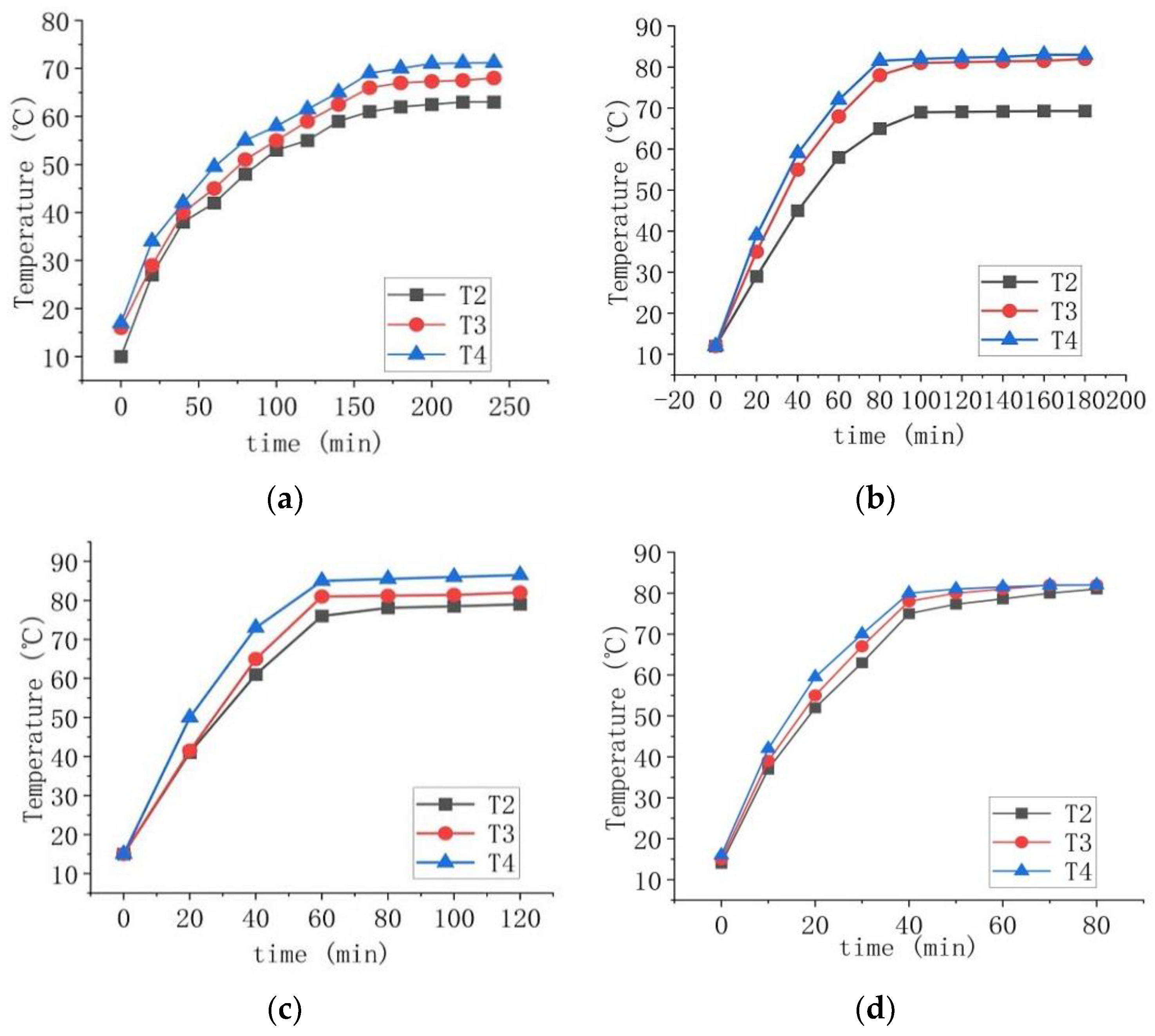
At an inclination angle of 90°, q = 444~1778 W·m−2, temperature profile change patterns of the experimental group are shown in Figure 4.
It can be observed from Figure 4 that the temperature profiles of q = 444 W·m−2, 889 W·m−2, 1333 W·m−2, 1778 W·m−2 experimental groups are slightly similar and divided into three stages according to the different rates of temperature rise.
(1) Apparent heat temperature rise stage: No obvious boiling phenomenon is found in the early stage, because at the initial stage, the liquid in the plate does not reach the evaporative phase change temperature at that pressure, and the fluid heat absorption is carried out through natural convection heat transfer.
(2) Boiling start stage: With the continuous increase in temperature, the boiling condition of water is reached, and bubbles gradually appear, and a small amount of steam generated enters the outlet pipeline. Bubbles continue to appear, and a small amount of steam gradually enters the export pipeline. There is still a low temperature liquid at the outlet, and the evaporating gas condenses at the outlet, causing the temperature to increase rapidly. Finally, the liquid level of the export pipeline drops, and the boiling state of the working mass reaches stability.
(3) Stable boiling stage: When the stable boiling stage is reached, the growth rate of the outlet temperature drops to the minimum. At the same time, the temperature rise rate of both the inlet pipeline and the plate starts to become smaller, and the temperature of each measurement point tends to be constant until it finally reaches stability.
With the increase in q, the stable temperature of the plate increases in turn. According to the table of thermophysical properties of saturated water, it can be seen that the working medium begins to boil, generating a small amount of steam, and the system flows more smoothly. The temperature of all parts of the horizontal plate is below 80 °C and the temperature distribution is relatively uniform, which meets the operating requirements of the fuel cell. If a preheating device is added to the inlet of the evaporator, it can make it reach the boiling condition faster and increase the heat transfer coefficient.
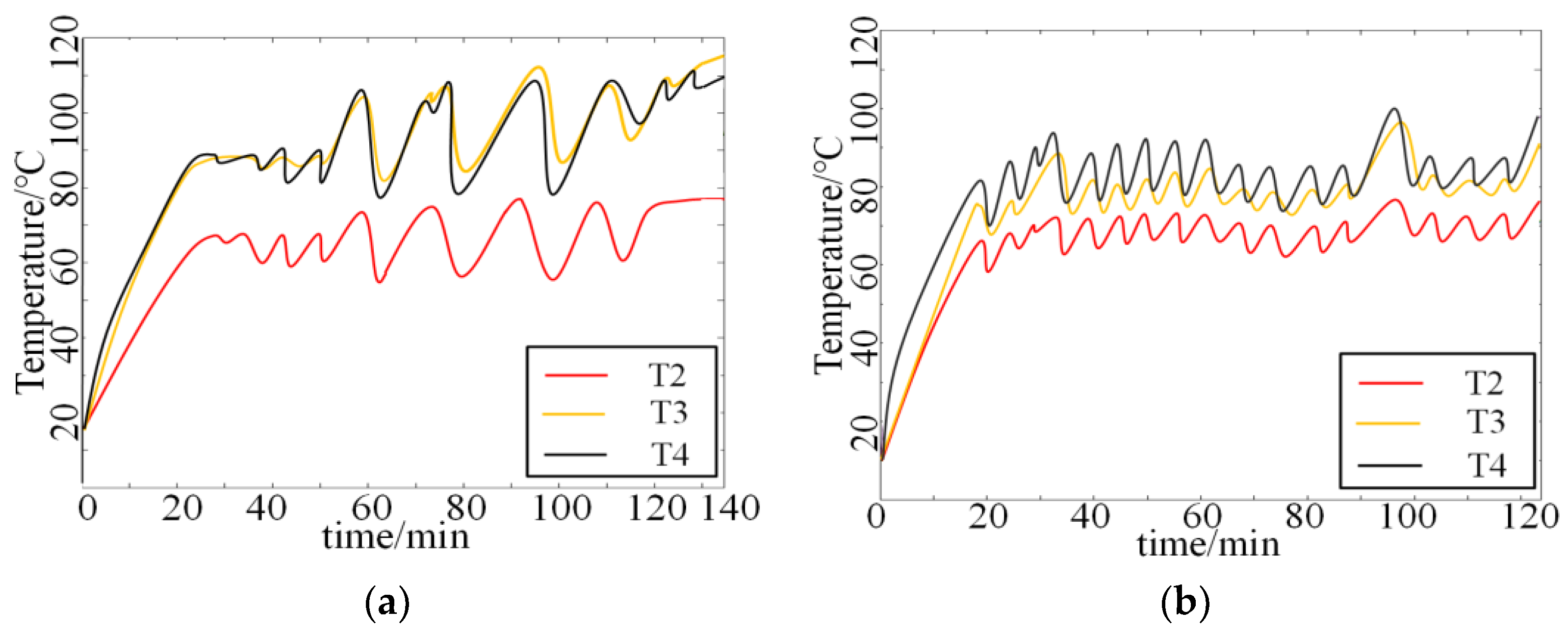
The oscillation of the temperature profile at an inclination angle of 90°, q = 2667~3111 W·m−2 is shown in Figure 5.
As can be seen from Figure 5, the temperature of each measuring point gradually increases with time, and the temperature curves of the q = 2667 W·m−2 experimental group begin to fluctuate at about 30 min and those of the q = 3111 W·m−2 experimental group at about 18 min. The q = 2667 W·m−2 experimental group, as seen from the stable boiling stage temperature curve, produced a strong oscillation, because q does not match the steam flow in the plate, so this heat pipe should be avoided as much as possible at this power as, at this time, similar to the pulsating heat pipe [19], the working medium oscillates between the inlet and outlet of the plate to achieve heat transfer. However, the heat pipe temperature oscillation is too strong at this time, which may result in an excessive temperature difference leading to excessive local thermal stress on the device, thus causing problems such as fracture of the welded joints and violent changes in surface temperature, leading to unstable fuel cell output and device damage. The temperature of each measurement point at q = 3111 W·m−2 repeatedly jumped up and down more frequently and could not be kept stable, indicating that the liquid feeding into the plate became more rapid and frequent. According to its temperature analysis, it is known that it is transition boiling, and bubbles converge to cover the inner surface of the plate, while the vapor discharge process is deteriorating. It not recommended to use this type of heat pipe in this range. If the power-type heat pipe is used to speed up the fluid flow, the circulation multiplier of the heat pipe system can be increased, and the strong oscillation of the horizontal plate temperature may be relieved by the right circulation multiplier.
The temperature profile of the measured points for the plate placed at an inclination of 90° at q = 3556~4444 W·m−2 is shown in Figure 6.
Similarities in the results of the three test groups can be seen in Figure 6. The temperature of the measurement points is not at the same level when q = 3556 W·m−2, and the temperature curve first undergoes a large oscillation, and then the amplitude of the oscillation decreases until it maintains an approximately stable state. More and more steam is produced at q = 4000 W·m−2, and the overall oscillation of the temperature curve begins to decrease, and the temperature can be kept stable for a long time. q = 4444 W·m−2 when the frequency of temperature oscillation is less, reaching stable film state boiling, and the heating surface forms a stable vapor film layer. The generated vapor regularly leaves the film layer. As q continues to increase, instead, the average temperature fluctuations are reduced and, at this time, the average temperature oscillation of the evaporator is reduced, the temperature fluctuations tend to stabilize, and become stable when the temperature has not seen a significant increase.
The reason why the temperatures at each measurement point are not at the same level is that the individual temperatures oscillate considerably under the perturbation of the incoming liquid. At the same time, in the upper, middle, and lower parts of the evaporator, the heat transfer mode is very different. In the lower part of the plate, the lower temperature of the mass is still dominated by the apparent heat temperature rise; in the middle of the evaporator, saturated water is converted into saturated steam for heat absorption; in the upper part of the plate, the steam generated is not smoothly discharged, causing its temperature to become the highest.
When the plate is set at 90° and q is small, the working medium in the plate begins to boil, the working medium produces a certain amount of evaporation, the heat transfer coefficient of the plate is improved, the temperature difference between the plates is small, and the temperature distribution is uniform, which is in line with the temperature requirement of fuel cells. When 2222 W·m−2 ≤ q ≤ 3111 W·m−2, the temperature oscillation of the heat pipe is too strong and the temperature distribution is not uniform, while the outlet temperature is too high, exceeding 80 °C. At this time, the gravity-type heat pipe cannot reach the normal working temperature of the fuel cell, and the power-type heat pipe should be used to solve this problem.

4.2. Effect of Tilt Angle on Fluid Boiling Heat Exchange in Evaporator

Different tilt angles have a large impact on the temperature distribution in the plate, which in turn affects the heat transfer and the degree of boiling of the heat exchange process. Figure 7 represents the variation of the average fluid temperature inside the plate at q = 444 W·m−2, 1333 W·m−2.
From Figure 7a, it can be seen that the time to reach stability is similar for each temperature measuring point, indicating that the angle change at q = 444 W·m−2 has little effect on the start-up duration of the experimental group. The reason for this result is because at this point a small amount of the working mass begins to boil, producing less steam, and the flow in the system is smoother, so the angle has little effect on it. Figure 6b shows that the temperature finally reaches 78 °C after the stable boiling stage at an inclination angle of 45° at q = 1333 W·m−2, which is the lowest value of the stable temperature at all angles, indicating that the cooling ability is relatively better at an inclination angle of 45° at q = 1333 W·m−2.
According to the experimental data for q = 444~4444 W·m−2, the stable operation stage of the average temperature of each point, taking the average of the inclination angle as the horizontal coordinate and the average value as the vertical coordinate, and the least squares quadratic polynomial fit are shown in Figure 8.
As can be seen from Figure 8, the tilt angle has a certain effect on the average temperature at stabilization, where q = 444 W·m−2 when the tilt angle has a greater effect on the average temperature at stabilization, q = 889 W·m−2, 1333 W·m−2 when the tilt angle has an effect on the average temperature at stabilization but the effect is small, and the average temperature of the plate placed at an angle of 45° is relatively low.
In summary, the average temperature of the mass in the plate at an inclination of 45° is relatively low and the temperature distribution is more uniform. The reason for the lower average temperature at 45° is that the circulating flow rate is higher: The liquid in the plate and inlet pipeline is under the combined effect of gravity, high pressure of the liquid in the condenser, low pressure in the outlet vapor area, and resistance to flow, forming a flow force and increasing the circulating flow rate; secondly, the flow paths of the outlet pipeline are extended upward, which makes it easier for the vapor to flow upward than at other angles. The rapid discharge of steam reduces the outlet pressure and increases the circulating flow rate of the working fluid. Therefore, the circulating flow rate of the system is raised, and the heat exchange effect is improved.

5. Conclusions

The experimental study of boiling heat exchange of water in parallel plates under negative pressure conditions led to the following conclusions.
(a) It is proved through experiments that a gravity-type heat pipe can dissipate certain heat, and it is feasible to use it for heat dissipation of fuel cells.
(b) When 444 W·m−2 ≤ q ≤ 1778 W·m−2 and 3556 W·m−2 ≤ q ≤ 4444 W·m−2, the overall temperature of the plate is around 80 °C and the temperature distribution is relatively uniform, which meets the requirement of homogeneity of fuel cells. When 2222 W·m−2 ≤ q ≤ 3111 W·m−2, the temperature difference between the top and bottom of the plate increases more than 15 °C, and the outlet temperature is too high, more than 80 °C, which exceeds the normal working temperature of the fuel cell, so the gravity-type heat pipe will not meet the requirements, and the power-type heat pipe should be used to solve the problems of high outlet temperature and uneven temperature distribution.
(c) Tilt angle has an effect on the average temperature at stabilization, including at q = 444 W·m−2, q = 889~1333 W·m−2 when the tilt angle has a smaller effect, and the average temperature is relatively low when the tilt angle is 45°. When q ≥ 1778 W·m−2, the average temperature of the plate placed at an inclination angle of 45°~60° is relatively low and the temperature distribution is more uniform.
Through the above tests, we can know that the gravity heat pipe has a certain effect on the heat dissipation of fuel cells, but there are also some shortcomings. Next, we will conduct more in-depth research on this problem, and solve this problem by combining the power-type heat pipe with the gravity-type heat pipe.

Author Contributions

Conceptualization, X.T.; methodology, X.T. and L.J.; software, L.J.; validation, L.J.; formal analysis, X.T. and L.J.; investigation, X.T., L.J., S.W. and J.G.; resources, X.T.; data curation, L.J. and H.L.; writing—original draft preparation, L.J.; writing—review and editing, X.T. and L.J.; visualization, X.T. and L.J. supervision, X.T.; project administration, X.T. and L.J.; funding acquisition, X.T. All authors have read and agreed to the published version of the manuscript.

Funding

This research received no external funding.

Data Availability Statement

Data is not available due to privacy or ethical restrictions.

Conflicts of Interest

The authors declare no conflict of interest.

Nomenclature

Nomenclature Greek Symbol
Aheat exchange area, [m2]αangle, [°]
hconvective heat transfer coefficient, [W·m−2·K−1]λthermal conductivity, [W·m−1·K−1]
Kheat transfer coefficient, [W·m−2·K−1]δthickness, [mm]
Llength, [m]subscripts
ppressure, [Pa]ehcelectric heating capacity
Qheat exchange capacity, [W]hpheat pipe
qheat flux, [W·m−2]hwhot water
qmmass flow, [kg·s−1]insthermal insulation material
Ttemperature, [K]sloss
ΔTtemperature difference, [K]spsingle-phase

References

  1. Li, J.; Yu, T. A new adaptive controller based on distributed deep reinforcement learning for PEMFC air supply system. Energy Rep. 2021, 7, 1267–1279. [Google Scholar] [CrossRef]
  2. Ala, G.; Colak, I.; Di Filippo, G.; Miceli, R.; Romano, P.; Silva, C.; Valtchev, S.; Viola, F. Electric Mobility in Portugal: Current Situation and Forecasts for Fuel Cell Vehicles. Energies 2021, 14, 7945. [Google Scholar] [CrossRef]
  3. Darges, S.J.; Devahdhanush, V.; Mudawar, I. Assessment and development of flow boiling critical heat flux correlations for partially heated rectangular channels in different gravitational environments. Int. J. Heat Mass Transf. 2022, 196, 123291. [Google Scholar] [CrossRef]
  4. Huang, J.; Xiang, J.; Chu, X.; Sun, W.; Liu, R.; Ling, W.; Zhou, W.; Tao, S. Thermal performance of flexible branch heat pipe. Appl. Therm. Eng. 2021, 186, 116531. [Google Scholar]
  5. Zhao, J.; Bu, Y.; Zhang, L. In Design and Performance of Heat Pipe Air-Conditioning Based on Latent Heat of Water Evaporation, Wuhan Hubei Province China. In Proceedings of the 2021 International Conference on Applied Mathematics, Modeling and Computer Simulation (AMMCS 2021), Wuhan, China, 13–14 November 2021; pp. 575–585. [Google Scholar]
  6. Zheng, N.; Fan, R.; Sun, Z.; Zhou, T. Thermal management performance of a fin-enhanced phase change material system for the lithium-ion battery. Int. J. Energy Res. 2020, 44, 7617–7629. [Google Scholar] [CrossRef]
  7. Zou, D.; Liu, X.; He, R.; Zhu, S.; Bao, J.; Guo, J.; Hu, Z.; Wang, B. Preparation of a novel composite phase change material (PCM) and its locally enhanced heat transfer for power battery module. Energy Convers. Manag. 2019, 180, 1196–1202. [Google Scholar] [CrossRef]
  8. Yu, G.Y.; Chiang, S.W.; Chen, W.; Du, H.D. Thermal Management of a Li-Ion Battery for Electric Vehicles Using PCM and Water-Cooling Board. Key Eng. Mater. 2019, 4838, 307–313. [Google Scholar] [CrossRef]
  9. Devahdhanush, V.; Mudawar, I.; Nahra, H.K.; Balasubramaniam, R.; Hasan, M.M.; Mackey, J.R. Experimental heat transfer results and flow visualization of vertical upflow boiling in Earth gravity with subcooled inlet conditions—In preparation for experiments onboard the International Space Station. Int. J. Heat Mass Transf. 2022, 188, 122603. [Google Scholar] [CrossRef]
  10. Chen, B.; Ho, K.; Abakr, Y.A.; Chan, A. Fluid dynamics and heat transfer investigations of swirling decaying flow in an annular pipe Part 1: Review, problem description, verification and validation. Int. J. Heat Mass Transf. 2016, 97, 1029–1043. [Google Scholar] [CrossRef]
  11. Liu, Z.-H.; Li, Y.-Y.; Bao, R. Thermal performance of inclined grooved heat pipes using nanofluids. Int. J. Therm. Sci. 2010, 49, 1680–1687. [Google Scholar] [CrossRef]
  12. Kumaresan, G.; Vijayakumar, P.; Ravikumar, M.; Kamatchi, R.; Selvakumar, P. Experimental study on effect of wick structures on thermal performance enhancement of cylindrical heat pipes. J. Therm. Anal. Calorim. 2019, 136, 389–400. [Google Scholar] [CrossRef]
  13. E, J.; Han, D.; Qiu, A.; Zhu, H.; Deng, Y.; Chen, J.; Zhao, X.; Zuo, W.; Wang, H.; Chen, J.; et al. Orthogonal experimental design of liquid-cooling structure on the cooling effect of a liquid-cooled battery thermal management system. Appl. Therm. Eng. 2018, 132, 508–520. [Google Scholar] [CrossRef]
  14. Kumar, V.; Vikash; Nigam, K. Multiphase fluid flow and heat transfer characteristics in microchannels. Chem. Eng. Sci. 2017, 169, 34–66. [Google Scholar] [CrossRef]
  15. Jige, D.; Inoue, N. Boiling heat transfer, pressure drop, and flow pattern in a horizontal square minichannel. Int. J. Heat Fluid Flow 2019, 78, 108433. [Google Scholar] [CrossRef]
  16. Bortolin, S.; Bortolato, M.; Azzolin, M.; Col, D.D. Comparative experimental procedures for measuring the local heat transfer coefficient during flow boiling in a microchannel. Exp. Therm. Fluid Sci. 2018, 90, 231–245. [Google Scholar] [CrossRef]
  17. Copetti, J.B.; Macagnan, M.H.; Zinani, F. Experimental study on R-600a boiling in 2.6 mm tube. Int. J. Refrig. 2013, 36, 325–334. [Google Scholar] [CrossRef]
  18. Shen, W.; Fan, L.; Pan, Z.; Chen, C.; Wang, N.; Zhou, S. Comparison of Different Topologies of Thermal Management Subsystems in Multi-Stack Fuel Cell Systems. Energies 2022, 15, 5030. [Google Scholar] [CrossRef]
  19. Zhang, D.; Li, H.; Wu, J.; Li, Q.; Xu, B.; An, Z. Experimental Study on the Effect of Inclination Angle on the Heat Transfer Characteristics of Pulsating Heat Pipe under Variable Heat Flux. Energies 2022, 15, 8252. [Google Scholar] [CrossRef]
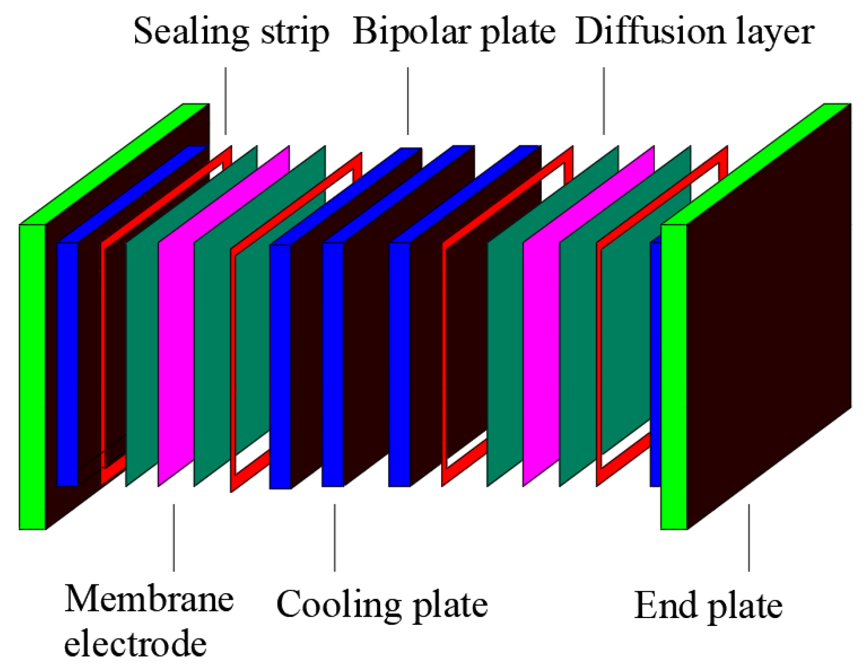
Figure 1. Schematic diagram of the structure of the proton exchange membrane fuel cell.
Energies 16 00563 g001
Figure 2. Schematic diagram of the experimental setup.
Energies 16 00563 g002
Figure 3. Experimental section measurement point arrangement scheme.
Energies 16 00563 g003
Figure 4. Temperature profile of heat flow density of 222~1778 W·m−2 at an inclination angle of 90°. (a) q = 444 W·m−2, (b) q = 889 W·m−2, (c) q = 1333 W·m−2, (d) q = 1778 W·m−2.
Energies 16 00563 g004
Figure 5. Temperature profile for heat flow density of 2667~3111 W·m2 at an inclination angle of 90°. (a) q = 2667 W·m−2, (b) q = 3111 W·m−2.
Energies 16 00563 g005
Figure 6. Temperature profile of heat flow density of 3556~4444 W·m−2 at an inclination angle of 90°. (a) q = 3556 W·m−2, (b) q = 4000 W·m−2, (c) q = 4444 W·m−2.
Energies 16 00563 g006
Figure 7. Average temperature profiles at different inclination angles for heat flow density of 444 W·m−2 and 1333 W·m−2. (a) q = 444 W·m−2, (b) q = 1333 W·m−2.
Energies 16 00563 g007
Figure 8. Fitted curve of the average value of stable operation temperature of heat flow density of 444~4444 W·m−2. (a) q = 444~1333 W·m−2, (b) q = 1778~2667 W·m−2, (c) q = 3112~4444 W·m−2.
Energies 16 00563 g008
Disclaimer/Publisher’s Note: The statements, opinions and data contained in all publications are solely those of the individual author(s) and contributor(s) and not of MDPI and/or the editor(s). MDPI and/or the editor(s) disclaim responsibility for any injury to people or property resulting from any ideas, methods, instructions or products referred to in the content.