1. Introduction
A battery energy storage system (BESS) is composed of series and parallel batteries. These arrangements are necessary to reach the required energy and voltage output [
1]. However, there is a challenge when batteries are associated in series. The elements have different charge amounts due to electrochemical mismatches. Moreover, after some time of use, multiple recharge cycles tend to increase those differences [
2]. For instance, Lehner et al. [
3] measured 700 new automotive cells and found a deviation from the mean capacity of
.
One of the major factors causing this capacity divergence is temperature gradients inside the
BESS [
4]. Those differences can happen due to different cooling or loading conditions. As an example, an evaluation of Li-ion storage installed in Germany shows that the state-of-health (SoH, the level of degradation, and remaining capacity of the battery) at lower temperatures decrease by 1%/year, while the
SoH at higher temperatures falls by 2%/year. Other factors associated with these differences are time and usage. Over time, Li-ion batteries tend to drift (regarding their capacities) since the electrochemical degradations behave differently for each cell [
5].
The main problem with a series of battery arrangements is that the total ’storable’ energy is dependent on the weakest battery. During discharge, the low-capacity battery empties first, forcing the entire storage (
BESS) to shut down. During the charge, due to its incapacity of the absorbing charge, it quickly reaches its maximum voltage and must also stop charging the entire bank. Hence, an energy equalization system [
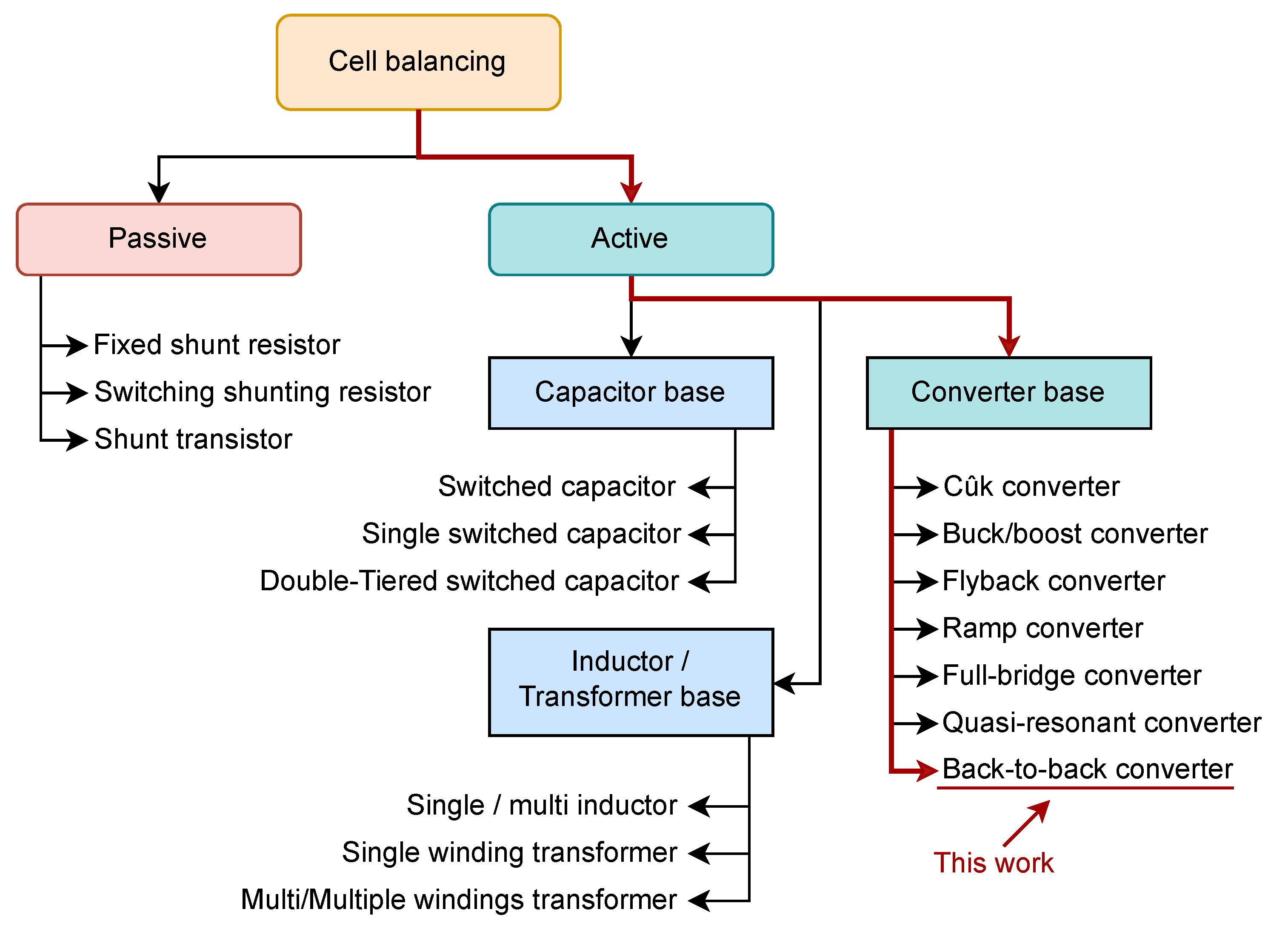
6] is necessary at the cell and battery levels, which can be classified as passive or active balancing structures, as
Figure 1 illustrates. The first type dissipates the excess energy in the form of heat, while the second type transfers the energy to the adjacent element.
This paper presents the technological evaluation of a series module-integrated converter for battery/cell equalization. The proposed design contribution shows the possibility of fully controlling the output voltage, which can speed up the balancing time and increase the balancing performance. The flexibility introduced is crucial to fully utilize the storage energy, even with a widely distributed charge range between the modules.
The system can also promote battery replacement since it can adjust individual capacities independently, which is not possible in equalization systems available on the market. With the proposed solution, only the weak battery is replaced, such that the maintenance costs drastically reduce and the batteries are fully used. In a similar manner, the presented technology can also operate with batteries from different manufacturers or technologies. In order to demonstrate those advantages quantitatively, an analysis based on linear programming is presented to compare the energy outputs of the available architectures.
The converter topology selected to introduce this new feature is a multi-leg back-to-back converter. The system integrates the converter at the battery level, as seen in
Figure 2, which is different from the alternatives at the cell level [
7]. This brings benefits in terms of volume and efficiency, while still keeping high capacity utilization and high utilization under fault [
8]. There are several other advantages to the presented modularization technique, such as its easy assembly and customization, the possibility of heterogeneous banks; system reliability improvement (due to lower stresses on the degraded batteries); the bypass of the defective batteries; and the ability to downgrade the performance while waiting for maintenance [
5].
In this research, since the system enhances the battery behavior, the joint (battery plus electronic) is named a smart battery (
SB) [
9,
10,
11]. The combination of
SB modules in series and parallel builds a smart battery bank that interacts with a charger,
Figure 2. A central controller (
CC) is responsible for managing the
SB bank and commands the individual SBs via a CAN bus. It receives the converter measurements, such as the battery voltage and current as well as the DC link and terminal voltages, and calculates the terminal voltage setpoint of each module, taking care to keep the voltage sum constant. The CC is also responsible for turning the modules on and off, ordering them to enter the bypass mode, or resetting any error condition.
This paper’s organization is as follows:
Section 2 elaborates on the model employed to access the performance of the parallel and series architectures;
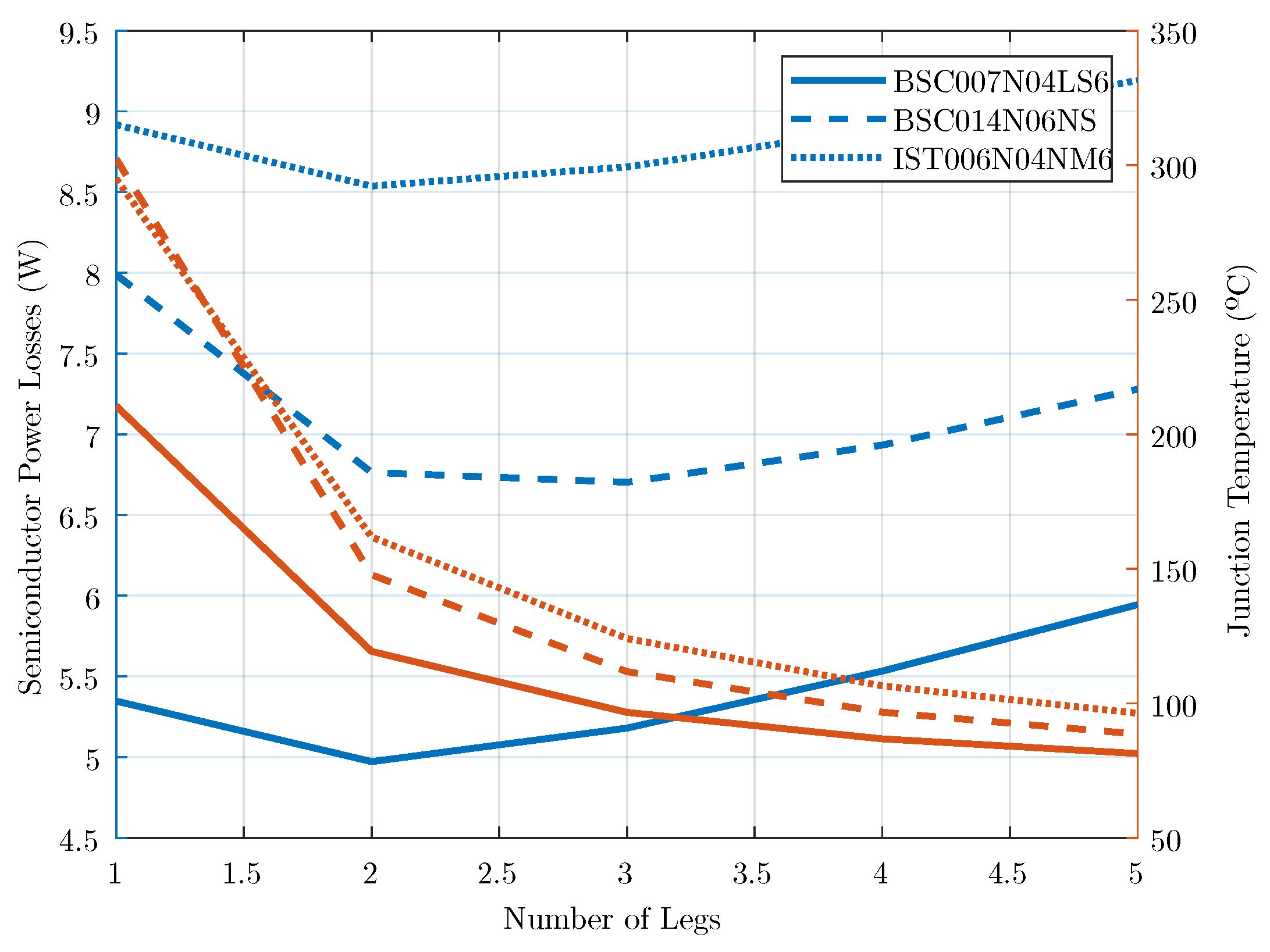
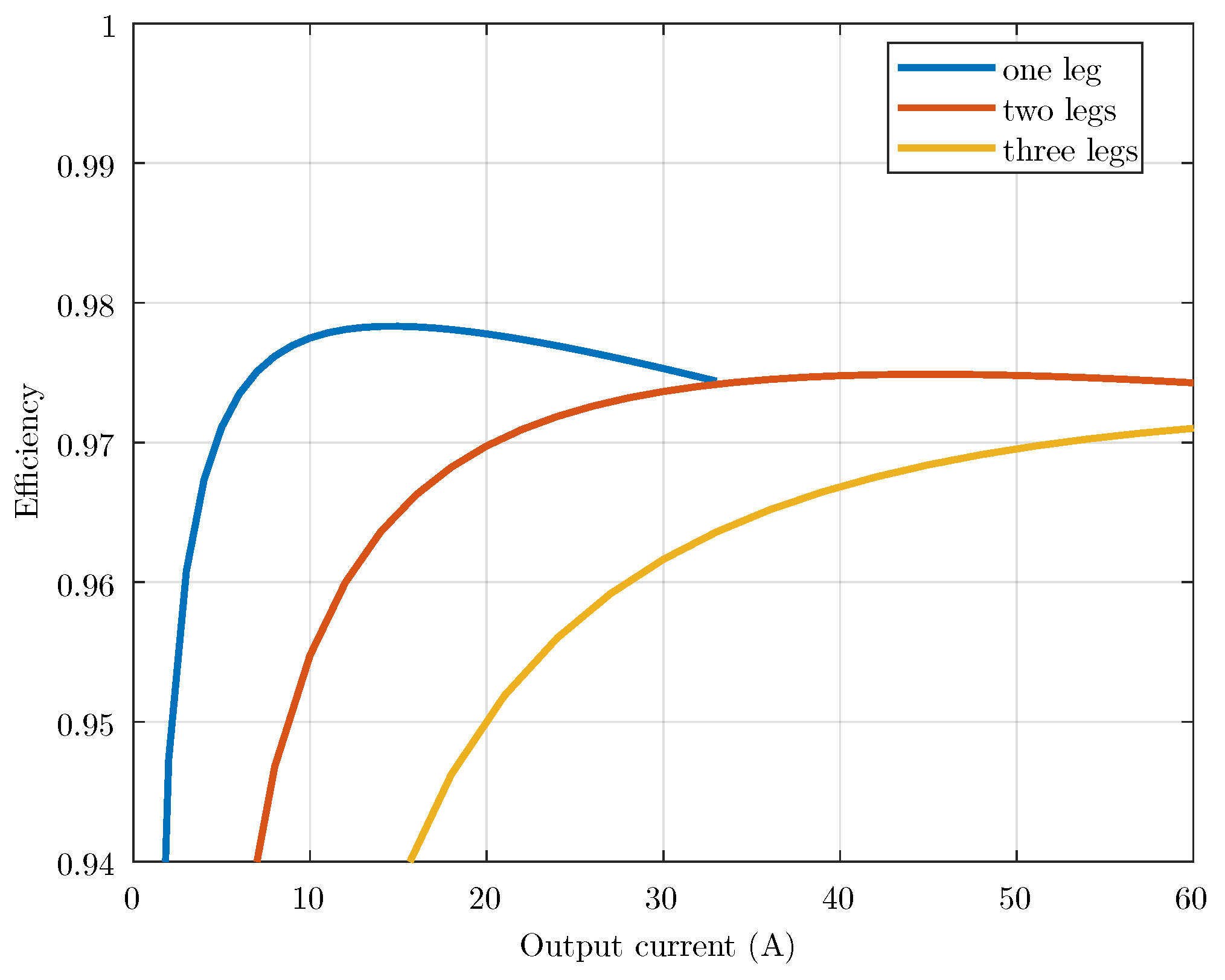
Section 3 details the converter design and shows the importance of restricting the number of switching legs under partial load;
Section 4 explains the converter’s control strategy, modeling, tuning, and implementation of the partial load strategy;
Section 5 presents the experimental setup and results; and
Section 6 presents the conclusions of this work.
2. Architecture Performance Comparison
There are some topologies for the active equalization proposition. The use of a converter base is the most suitable since it enables more degrees of freedom to adjust the power flow between elements [
12]. In order to compare those differences, a summary comparison is presented in
Table 1.
Among the active balancing circuits, the most common one used in the literature is energy redistribution balancing, which can be classified based on the architecture, such as adjacent cell-to-cell (
C2C), direct cell-to-cell, and cell-to-pack (
C2P) [
13]. The latter architecture can be further divided into parallel or series.
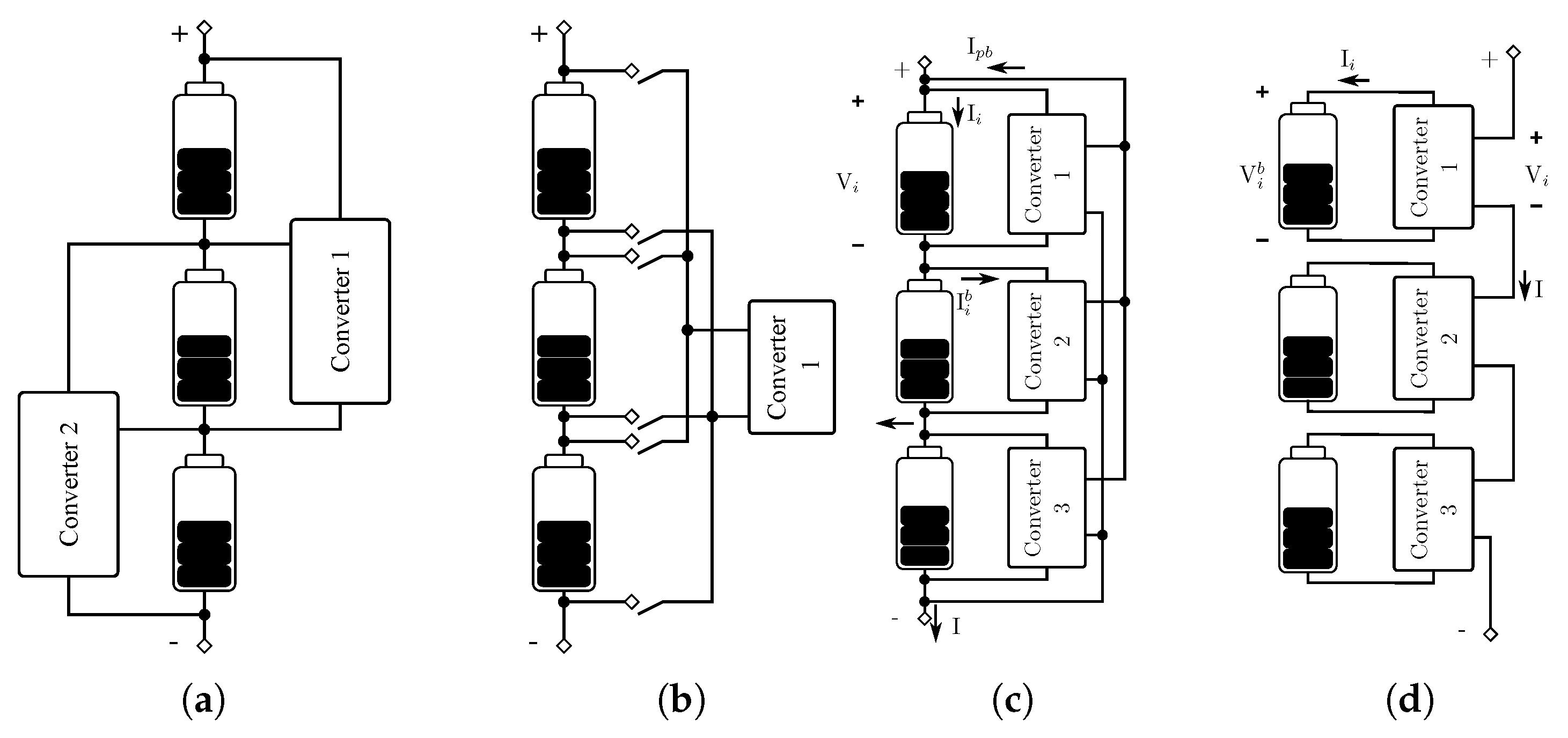
Figure 3 illustrates each strategy.
In the adjacent cell-to-cell architecture,
Figure 3a, energy is only transferred between adjacent cells. This is a simple and often adopted solution that has been the object of many works proposed for different converter topologies or balancing algorithms [
14]. Its main drawbacks are its low efficiency, as the energy flows through many converters when cells with wide differences in capacity are far apart, and the low equalization speed that decreases as the number of cells increases [
15].
In the direct cell-to-cell architecture, as seen in
Figure 3b, energy can flow between any two cells of the pack. For example, authors from [
16,
17] propose an inductor as the storage element and an association of MOSFETs and diodes as switches. This architecture’s main drawback is the low equalization speed since only a pair of cells are charged/discharged at a time. A hybrid adjacent/direct cell-to-cell architecture was proposed in [
18].
In the parallel cell-to-pack architecture, as seen in
Figure 3c, the energy transfer takes place between individual cells and the whole pack. Several authors have proposed different converter topologies for the realization of this architecture, e.g., [
2,
19,
20,
21,
22]. An important drawback of this architecture is that the pack side of the converter must withstand a higher voltage and the converter has a high primary/secondary voltage ratio that compromises efficiency.
In the series cell-to-pack architecture, as seen in
Figure 3d, energy transfer happens between the individual modules (cell plus converter) and the pack, but this process is more subtle since the modules are simply connected in series. The pack current flows through the string, but the converter controls the module terminal voltage. As a result, the energy supplied to or drawn from each module is proportional to the individual module terminal voltage. An example of the series cell-to-pack architecture involves the use of a cell-integrated bidirectional buck converter [
7]. In a different approach [
1,
23,
24], the modules operate in a bypass or inserted mode, in which the battery current is zero or equal to the pack current, respectively (the latter could also be classified as duty cycle balancing [
13]).
The converter in the C2P series architecture has a 1:1 ratio and needs only low-voltage switches. It favors battery–converter integration, since the resulting module remains with two terminals, and the connections to the pack’s positive and negative rails are avoided. However, the practical implementations proposed in the literature limit the module terminal voltage values, as they can only be higher or lower than the battery voltage since only step-up or step-down topologies have been proposed so far. This limited range compromises the ability to extract all of the stored energy from the bank when the battery capacities range widens, as will be shown in this work.
This section extends the work of Chatzinikolau and Rogers [
13], who evaluated the performances of power electronic-enhanced battery packs through the use of linear programming optimization. Linear programming, in this work, is a tool to compare the performances of different architectures, but it has no influence on the system operation.
The performance of the parallel cell-to-pack (C2P) bank, as developed in [
13], is repeated here, and compared with the performance of the C2P series. The modeling and development of the performance assessment of the C2P series bank is the contribution of this work, as [
13] compared the architecture’s parallel C2P, adjacent C2C, and direct C2C. Two implementations of the C2P series are considered: the bidirectional buck converter [
7] and the proposed back-to-back converter.
2.1. Parallel Cell-to-Pack
In a parallel C2P topology, the average battery
i current is (
1),
where
I is the pack current,
is the average balancing current extracted from the battery
i, and
is the total balancing current that is returned to the pack, as indicated in
Figure 3c. The extracted power from the battery and delivered to the pack is (
2),
where
is the converter efficiency, considered constant,
is the module voltage, and
N is the number of batteries. Considering equal battery voltages,
will be (
3). The average balancing current extracted from module
i can be modeled as (4), where
is the converter current capacity (
),
T is the length of a full charge or discharge cycle, and
is the total time during which energy is transferred from module
i to the pack.
Therefore, replacing (
3) and (4) in (
1) leads to an average battery current described by (
5). The first term corresponds to the pack current, the second term to the balancing current extracted by the converter, and the third term to the sum of the currents injected by all modules back in the pack.
If the capacity of each battery,
,
is the usable charge of module
i in a complete discharge cycle, where
. With the pack current held constant (
6),
The combination of (
5) and (
6) makes the operation length equal to (
7). From (
1), (
5) and (
7), we can derive (8).
The length of operation
T will always be less than or equal to the maximum possible time, which corresponds to the full utilization of batteries energy, i.e.,
. Hence, the inequality (
9) holds.
2.2. Series Cell-to-Pack
In the C2P series architecture, the current flowing through the module terminals (secondary of the converter) is equal to the pack current
I and, from the power balance, the battery current
is (
10),
where
is the battery voltage and
is the module voltage, as indicated in
Figure 3d. The balancing current,
, is modeled proportionally to an equivalent balancing time
(
11), which is a function of the module and converter voltages (12).
The operation length (
13) is obtained from (
6), (
10), and (
11), and combining (
1), (
10) and (
13) leads to (14).
Finally, the length of operation
T is less than or equal to the maximum possible time, just as in (
9), which results in (
15).
2.3. Additional Bidirectional Buck Constraints
At first look, the bidirectional buck converter of [
7] is simpler and cheaper than the proposed topology. However, it has important operational restrictions that limit the pack’s extractable energy. The first one (
16) is on the module terminal voltage
, which must be higher than in the battery voltage
and lower than an upper limit
. A second restriction (17) must be considered when the bank is connected to a commercial charger to feed energy to the grid, because the bank voltage,
, is also constrained to
, where
is the maximum battery voltage.
Using (12), (
16) and (17) are translated into the decision variable
constraints (
18) and (19).
2.4. Additional Back-to-Back Constraints
The proposed converter also has constraints on its terminal voltage, but they are less strict than the previous case. The output voltage can be as low as
and as high as the DC link voltage
(
20). The maximum bank voltage restriction also applies and it is necessary to consider a lower limit proportional to the battery minimum voltage,
; hence, (21).
Using (12), (
20) and (21) are translated into the decision variable
constraints (
22) and (23).
2.5. Linear Programming Optimization
The linear programming optimizations seek the decision variable vector
that minimizes
, where
and
are matrices,
,
,
, and
are vectors that define inequality, equality, and range constraints (
24).
In this work, the decision variable is
. Following the development of the previous sub-sections,
and
are derived from (
9) and (
15),
, and
are derived from (8) and (14) for the parallel and C2P series architectures, respectively. The range
applies to all architectures, while for the parallel C2P,
is valid, and for the C2P series, (
18) and (19) must be considered for the bidirectional buck topology and (
22), and (23) for the proposed back-to-back topology.
Once all matrices and vectors are defined, the linprog() MATLAB function processes the parameters to find the and , for , which maximize the energy output , given a certain set, battery voltage, and charge/discharge current.
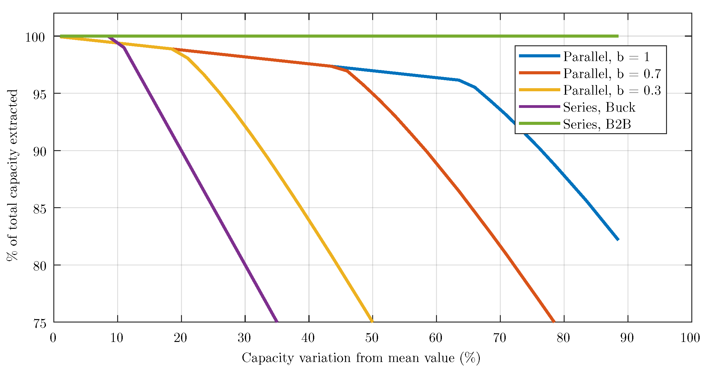
To assess the performance differences between the implementations,
Figure 4 shows the evaluation of a 20-module bank in which the battery capacity is uniformly distributed in a range from 0.2 to 1.8 Ah, always with a mean capacity of 1 Ah and a discharge current of 1 A. For example, if the pack has three batteries and the capacity distribution is 0.4 Ah, the battery capacity will be 0.8 Ah, 1.0 Ah, and 1.2 Ah.
Table 2 shows the remaining parameters employed.
The evaluation shows that the bidirectional buck converter is unable to extract full energy when the capacity distribution is 10%; when the distribution is 30%, it can only use 80% of the full capacity. The parallel C2P architecture performance has the influence of the converter current capacity modeled through the b parameter. For current capacities of 0.3I, 0.7I, and 1I, the energy extracted starts to fall fast when the capacity distributions are 20%, 0.45%, and 0.65%, respectively. On the other hand, the proposed C2P series implementation can extract all of the bank energy for the capacity distribution evaluated. The tests with different numbers of modules, capacities, and discharge currents returned similar results and are omitted.
This result shows that the proposed solutions are only able to extract the entire energy available in a battery bank, independent of the capacity and state of health of each module. This is important, as the batteries degrade differently over time, which tend to cause their capacities to drift apart, as already discussed. Another typical application is the second life of a battery bank since its elements naturally have heterogeneous capacities and SoH.
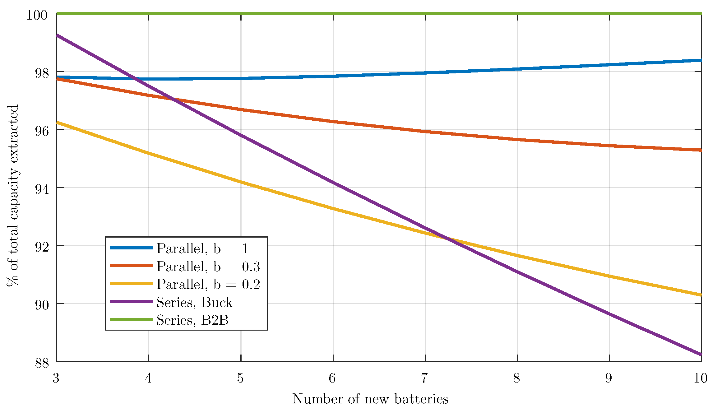
Another benefit is the opportunity to replace the batteries individually as they reach their end of life, as the other solutions are unable to cope with the large capacity differences that will appear as new batteries are introduced in banks with old ones. To evaluate this latter case of a bank with old batteries (that has a few replaced by new ones), the results of the linear programming are presented in
Figure 5. A bank with 20 batteries is considered and the old batteries have a mean capacity of 0.7 Ah with a uniform distribution of ±0.10 Ah. To this bank,
x new batteries replace the old ones, each with a mean capacity of 1.0 Ah with a uniform distribution of ±0.02 Ah. The graph shows the percentage of the total stored energy that the system can extract depending on the architecture adopted. Again, the proposed architecture using the back-to-back converter is the only one that can fully utilize the bank in all conditions. The parallel architecture also reaches high utilization, as long as the converter rating is high enough (in the simulated case, with a b > 0.35). The series architecture with a step-up converter has the worst performance when 12% of energy is not reachable when the bank is half old–half new.
The results obtained with the linear programming optimization show that the proposed solution performs better if compared with the other architectures proposed so far and brings high flexibility to the systems, opening up possibilities, such as replacing EoL batteries, which are often ignored.
4. Control
The smart battery system has a hierarchical control, with a local controller at each smart battery module and a central controller. During operation, the central controller (CC) receives values of the voltage, current, and temperature from each battery through the communication bus. It then calculates SoC and, based on historical data, it estimates SoH. Because the load demand is known, the CC calculates the RFE voltage references to reach optimum battery throughput and maximum bank capacity.
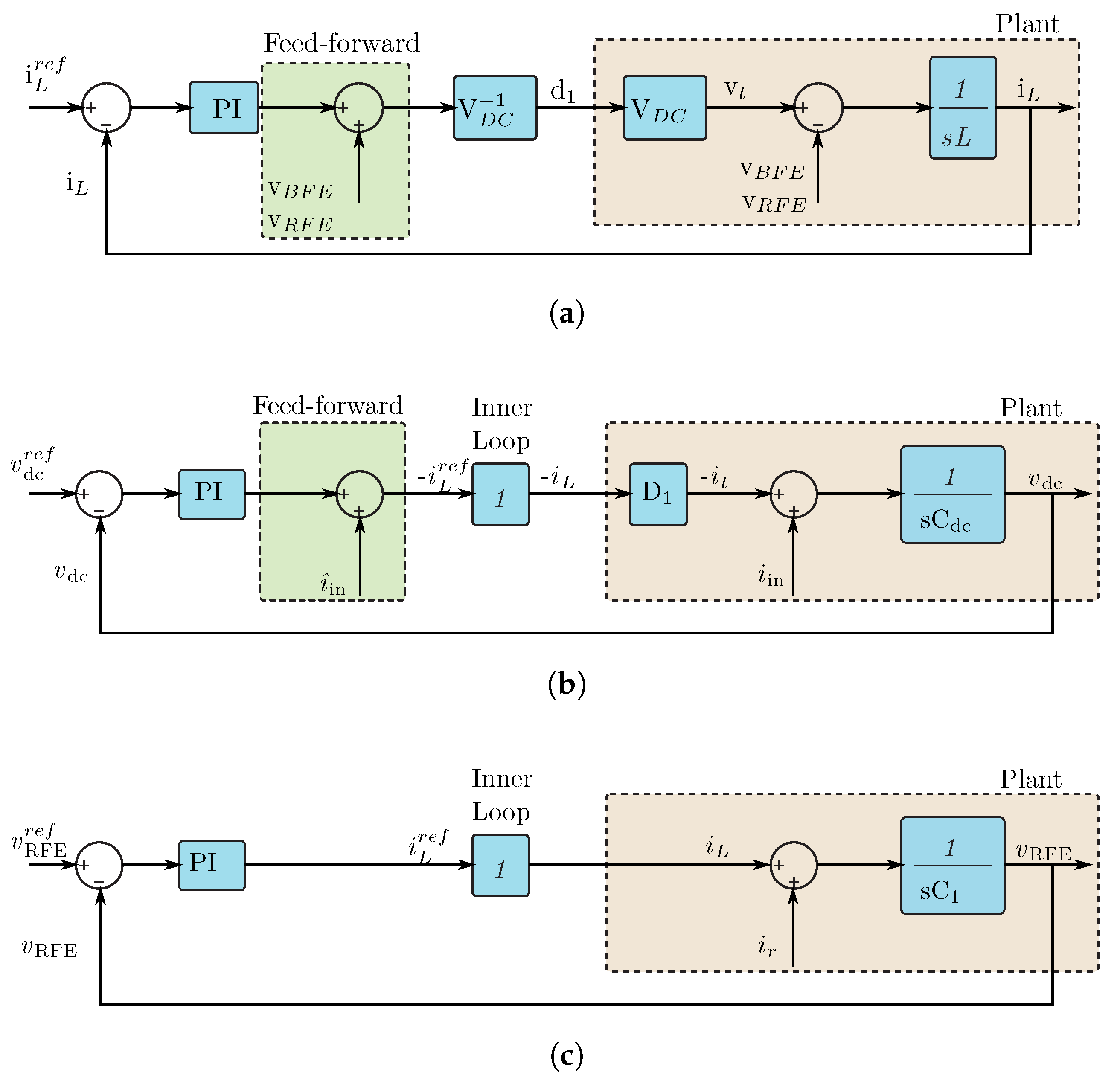
The local controller (on both the BFE and RFE) implements an inner loop to regulate the inductor currents, . In the BFE, an outer loop controls the DC link voltage, . As a consequence, the battery current follows the power balance, i.e., . The RFE seeks to emulate the voltage source behavior of a battery by controlling the terminal voltage .
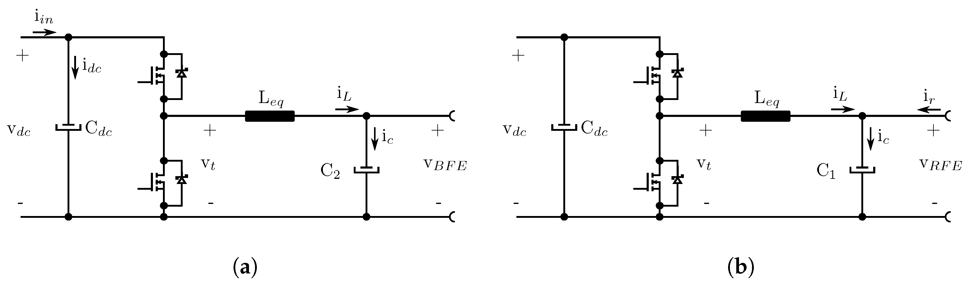
By modeling the converter as an equivalent single-leg circuit,
Figure 8, the inductor current (
32), DC link (33), and RFE terminal voltage dynamics (34) can be extracted,
where
is the equivalent inductor equal to the leg inductor divided by the number of legs;
is the half-bridge synthesized voltage;
is either the battery or the RFE voltage;
and
are disturbance currents flowing to the DC link and the filter capacitor
, respectively;
is the converter’s duty cycle at the analyzed point of operation; and
and
are the RFE and DC link capacitors, respectively.
Figure 9a–c show the block diagram of the inductor current, DC link voltage, and RFE voltage control loops, respectively.
The control loops use proportional–integral controllers with feed-forward terms, one at the current loops and another at the DC link voltage loop. The first term is the measured battery or RFE voltage (
Figure 9a) and the second term is the calculated input current reflected at the low side,
, calculated assuming the power balance between BFE and RFE (
Figure 9b). The control loop tuning employed pole placement using the parameters listed in
Table 5.
Current Equalization
In addition to the main converter controller, it is necessary to include a loop to equalize the converter leg currents. The selected approach uses the current from one leg as the reference and calculates the differences between the currents in each of the remaining legs and the reference one. The error is multiplied by a constant that produces a
to modify the leg’s duty cycle (
35).
This approach has some interesting advantages. First, it reduces the microcontroller load, since the number of control loops is constant and independent of the number of legs; second, under a partial load, it simply enables or disables the leg-switching pulses. Once a leg starts switching, the equalization control loop takes care of the current sharing.
5. Experimental Results
A prototype was built, which comprises two boards: a control board,
SB_CTRL, and a power board,
SB_POWER. The module prototype is connected to a lead acid 240 Ah battery (
Figure 10) and the main system characteristics and converter parameters are summarized in
Table 3 and
Table 6.
A series of experiments were conducted in order to evaluate the electronic boards and the proposed control. The
SB_CTRL was first tested using a hardware-in-the-loop (
HiL) platform and the results are presented in
Figure 11. The adopted equipment is a Typhoon HiL model 604. This step was used to develop the firmware of the system. Moreover, the HiL was used for the long-term discharge and charge operation and validation. The
HiL simulations included a complete SB bank, such that the
CC software was also validated prior to the tests in the power bank [
12]. As an example, the
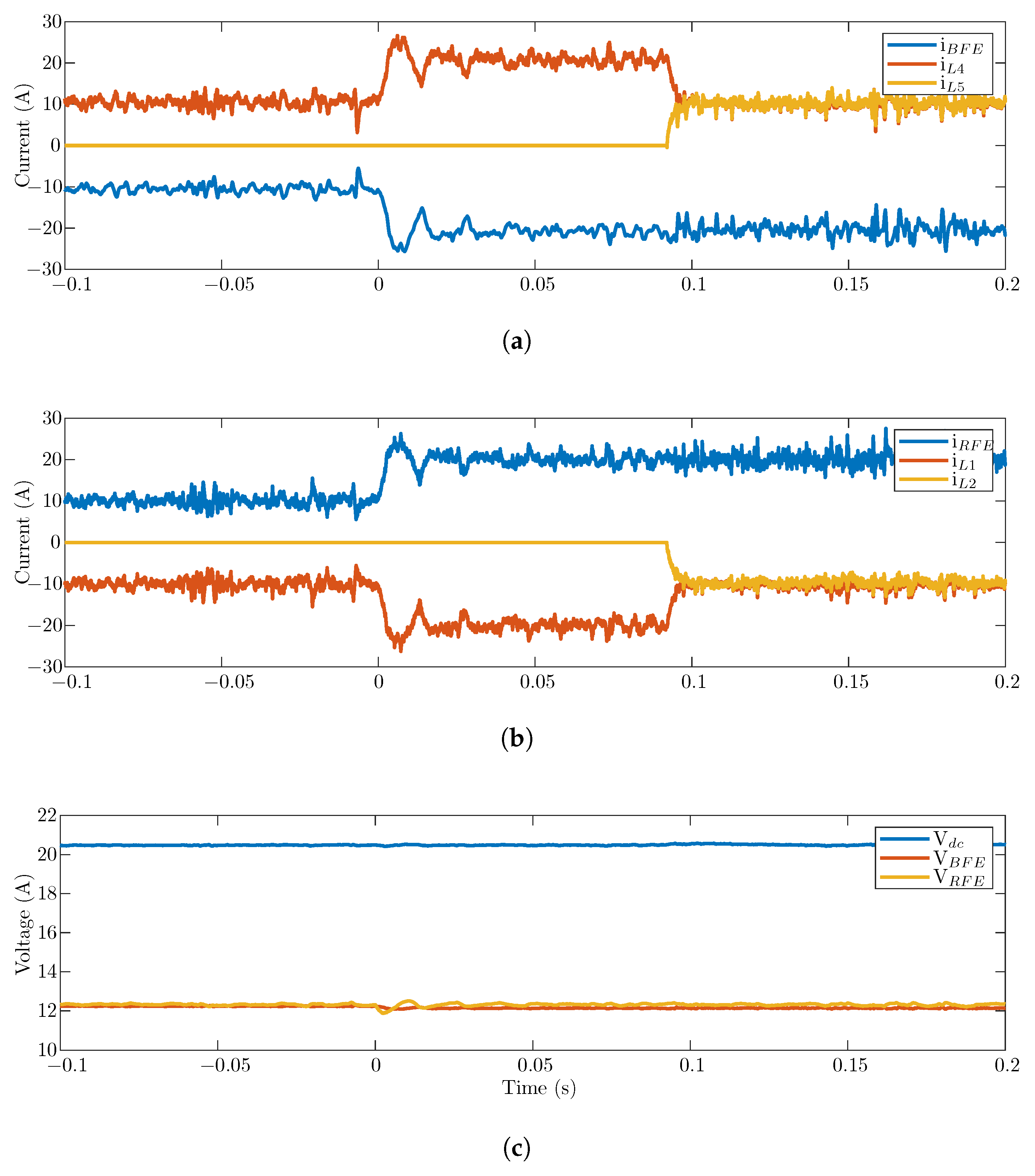
HiL simulation validates the control response to a load transient that causes the second leg to start switching.
Figure 11 shows the regulation of the RFE and DC link voltage, where
and
are the leg currents of the BFE converter and
and
of the RFE converter. It also demonstrates that the second leg enters the switching mode seamlessly, as seen by the external quantities.
After the HiL validation, the firmware and control implementation were tested through an experimental setup consisting of a power bank with three series-connected SB modules and the central controller.
Figure 12 presents the results of a long-term experiment using lead acid batteries with a capacity of 240 Ah (C20), model 12MS234, manufactured by Moura. The initial conditions of the experiment were set, such that the battery of SB2 was near full charge, SB1 was only half-charged, and the SB3 charge was between the other two.
The experiment consisted of the power bank subjected to 10 A constant current charge/discharge cycles imposed by a DC controllable power source. Initially, for up to 10 min (see the expanded view of the battery currents in
Figure 12d), the control balance was disabled. Watching the battery terminal voltage (
), it was noticeable that capacities were uneven between elements. When an element reached its maximum voltage, the entire system stopped charging and started to discharge. Likewise, when an element reached its minimum voltage, it started to recharge.
During the first cycles, SB2 quickly hit its full charge (SoC 95%). This behavior is shown by the red line of . During discharging, SB1, presented by the blue line of , quickly reached the limit of discharge (SoC 50%).
After those initial cycles, the active balancing was enabled and it started to modify the voltage references, such that during discharge, the battery with higher SoC delivered the larger current and, during charge, the battery with lower SoC obtained a larger current. Notice that the control actions on the RFE voltages set the proper charges supplied/drawn from each battery.
The cycle after the system managed to balance the charge in the batteries. The discharge time of the bank significantly increased from 25.2 min at the first cycle () to 62.1 min (). Since the discharge current and the power bank voltage were held constant (10 A and 36 V), the total energy delivered was directly proportional to the discharge time. After several cycles, the bank discharge time exceeded 100 min. This experiment demonstrates that the proposed strategy allows extracting 38.8 times more energy from the same battery bank when compared to the operational equivalent in a passive bank.
6. Conclusions
Power electronics can increase a battery energy storage system’s lifespan, performance, and efficiency, as well as reduce investment costs. This paper proposes the use of a back-to-back converter in a series of cell-to-pack architectures. A quantitative evaluation using linear programming proved that this implementation can extract full energy from the bank even when the battery capacities are spread over a wide range—a feature that is absent in other proposed solutions found in the literature.
The proposed solution simplifies the module’s integration and has several other benefits, such as easy assembly and customization, higher system reliability, and the possibility to downgrade the power bank performance while waiting for maintenance. Furthermore, the ability to operate the BESS with heterogeneous storage elements, i.e., batteries of different technologies or ages (new batteries together with old ones), from several manufacturers, reduces operational costs, since only elements that reach end-of-life have to be replaced, and the bank owner can select the battery with the best cost–benefit ratio at the time of the replacement.
This work presents the technological perspectives of the converter and control design. Moreover, a prototype was built and validated through experimental results. A three-series module power bank was built, showing how the battery’s energy storage capacity utilization is greatly improved with the proposed solution. The strategy of reducing the number of switching legs improves the efficiency under a partial load and reduces the impacts of losses regarding the module’s overall performance. It is important to highlight that the SB bank can deliver much more energy than a passive one.


