Article

A Modified Particle Swarm Optimization Algorithm for Power Sharing and Transient Response Improvement of a Grid-Tied Solar PV Based A.C. Microgrid

1
School of Electrical Engineering, Southeast University, Nanjing 210096, China
2
Department of Mechanical Engineering, Mehran University of Engineering and Technology, SZAB Campus, Khairpur Mirs 66020, Pakistan
3
Department of Electrical Engineering, Mehran University of Engineering and Technology, SZAB Campus, Khairpur Mirs 66020, Pakistan
4
School of Electrical Engineering, Beijing Jiaotong University, Beijing 100044, China
5
Department of Electrical Engineering, College of Engineering, Jouf University, Sakaka 72388, Saudi Arabia
*
Author to whom correspondence should be addressed.
Energies 2023, 16(1), 348; https://doi.org/10.3390/en16010348
Submission received: 19 November 2022 / Revised: 15 December 2022 / Accepted: 23 December 2022 / Published: 28 December 2022
(This article belongs to the Special Issue Control and Protection of Hybrid AC/DC Transmission Systems)

Abstract

:
The increasing penetration of Distributed Generators (D.G.) into the existing power system has brought some real challenges regarding the transient response of electrical systems. The injection of D.G.s and abrupt load changes may cause massive power, current, and voltage overshoots/undershoots, which consequently affects the equilibrium of the existing power system and deteriorate the performance of the connected electrical appliances. A robust and intelligent control strategy is of utmost importance to cope with these issues and enhance the penetration level of D.G.s into the existing power system. This paper presents a Modified Particle Swarm Optimization (MPSO) algorithm-based intelligent controller for attaining a desired power-sharing ratio between the M.G. and the main grid with an optimal transient response in a grid-tied Microgrid (M.G.) system. The proposed MPSO algorithm includes an additional parameter named best neighbor particles (rbest) in the velocity updating equation to convey additional information to every individual particle about all its neighbor particles, consequently leading to the increased exploration capability of the algorithm. The MPSO algorithm optimizes P.I. parameters for transient and steady-state response improvement of the studied M.G. system. The main dynamic response evaluation parameters are the overshoot and settling time for active and reactive power during the D.G. connection and load change. Furthermore, the performance of the proposed controller is compared with the PI-PSO-based MG controller, which validates the effectiveness of the proposed M.G. control scheme in maintaining the required active and reactive power under different operating conditions with minimum possible overshoot and settling time.

1. Introduction

Due to the rapid increment in population and electrical appliances in the recent decades, electrical energy consumption has increased significantly. Also, there is a worrying situation as fossil fuels are depleting markedly faster from the globe. Distributed Generators (D.G.) have become essential for maintaining living standards and healthy environmental conditions to overcome the stated issues. These D.G.s can be operated alone, supplying limited power to a home or a community or constitute a Microgrid (M.G.). An M.G. is an interconnection of D.G.s and battery storage that provide electricity and heat to the local community [1,2,3].
There are two modes of M.G.’s operation; islanded and grid-connected. In islanded mode, the M.G. is operated to fulfill the electrical power needs of the local community [4]. The major concern in this mode of operation is to regulate the voltage and frequency of the system according to the set standards [5]. Hence the inverter follows the v-f control mode. While in the grid-tied mode, the M.G. is coupled with the main grid to share the electrical power with the main grid. In this case, the voltage and frequency regulation is not an M.G. concern as the giant power system dictates it [6]. In contrast, active and reactive power needs to be regulated according to the pre-set reference power values. Generally, a power electronic-based interface like pulse width modulated voltage source inverter (PWM-VSI) or converter is needed to connect the M.G. with the utility grid [7,8,9,10]. This PWM-VSI produces non-linearity between voltage and current, resulting in power quality problems like harmonic distortion and transients. To overcome these power quality problems and ensure the smooth integration of renewable energy sources, a robust control strategy is of utmost importance, hence the motivation of this research work.
Recent studies [11,12,13,14,15] have proposed some control loops for controlling active and reactive power in grid-connected M.G.s. In these control architectures, the first control loop is generally a power control loop. The primary purpose of this control loop is to generate a current reference signal from active and reactive power references with the help of conventional P.I. controllers due to their simplicity, feasibility, easy implementation, and robustness. However, their performance is purely dependent on their control gains (Kp and Ki) which are generally selected by “trial and error” or the well-known Ziegler Nichols (Z-N) method. The trial-and-error method for P.I. tuning is a lengthy and time-consuming process. Ultimately, it does not ensure the optimal selection of P.I. gains. The Z-N method is a trial-and-error tuning method based on sustained oscillations [16]. To avoid these lengthy and time-consuming processes of P.I. controllers tuning, authors in recent studies have used different metaheuristic techniques like the Genetic Algorithm (G.A.) and PSO to tune the P.I. controllers for enhanced dynamic M.G. performance optimally. Although the conventional PSO has been found very effective in obtaining the optimal response in many research articles, it has some serious issues that need to be addressed. Some of these drawbacks include its inferior convergence behavior in the optimization process, stagnation into a local solution in high-dimensional space [17], and ambiguity in its parameter adaption [18]. It works better in the initial iterations but finds problems reaching an optimal solution in some benchmark functions.
In this paper,
  • To avoid the stated problems associated with conventional PSO, an improved version of the same algorithm called modified particle swarm optimization (MPSO) has been incorporated in the M.G. control structure for minimization of fitness function (F.F.) which is ITAE in this case.
  • Contrary to the original version, the proposed MPSO algorithm includes an additional parameter named best neighbor particles (rbest) in the velocity updating equation to convey additional information to every individual particle about all its neighbor particles, consequently leading to increased exploration capability of the algorithm.
  • Thus, the optimized control parameters obtained at the end of the simulation ensure improved transient response and power-sharing during the M.G. connection and load changes.
  • Furthermore, the performance of the proposed controller with the optimal parameters has been examined through the nonlinear time-domain simulation.
  • The results show the proposed approach’s effectiveness in minimizing the overshoot, settling time, and extracting the reference power.

2. Modeling of the Grid-Tied Microgrid along with the Proposed V.S.I. Control Architecture

Solar PV is taken as D.G. in this case study due to the availability of solar insolation in abundant quantity and easiness in extracting its maximum power point as compared to other forms of D.G.s. Furthermore, its easy installation on-site, portability, cost-effectiveness, and high life span make it an attractive choice for M.G. systems. As the output power of the solar PV is in D.C. form, a D.C. to A.C. conversion is needed to interface it with the local A.C. power system. For this purpose, an IGBT-based V.S.I. is chosen for this case study due to its availability with different power ranges and some other prominent benefits as compared to its counterpart power electronic switching devices [6]. A typical circuit for a three-phase V.S.I.-based D.G. in grid-tied mode with an L.C. filter is considered in this study as shown in Figure 1.
In Figure 2, the Rf, Lf, and cf represent the value of resistance, inductance, and capacitance of inverter filter respectively while Vabc and Iabc are three-phase grid voltages and currents respectively. The state-space Equation of the corresponding circuit in abc reference frame is given by [8].
d d i i a i b i c = R s L s i a i b i c + 1 L s V s a V s b V s c V a V b V c
V s a , V s b and V s c represents per phase grid voltage while V a , V b and V c represents per phase D.G. output voltages. By using Park’s Transformation Equation (1) can be written in dq reference frame as,
d d t i d i q = R f L f ω ω R f L f i d i q + 1 L s V s d V s q V d V q
ω denotes the angular frequency while V s d , V s q and V d , V q are the grid and D.G. voltage in dq reference frame respectively. Further Park’s Transformation can be expressed as
i d q 0 = T . i a b c
where,
T = 2 3 cos θ cos θ 2 π 3 cos θ + 2 π 3 sin θ sin θ 2 π 3 sin θ + 2 π 3 1 2 1 2 1 2
θ = ω s t + θ 0 ; which is the synchronous rotating angle, θ 0 represent the initial value of the angle.

Proposed Power Control Strategy

The proposed power control strategy for 3-phase V.S.I. based D.G. using MPSO for power flow controller is consists of three main sections, namely droop control, power control, current control as depicted in Figure 2.
Initially, the output voltage and current signals are measured and converted from abc to dq frame of reference using the well-known Park’s transformation. This is necessary because the P.I. controllers do not track sinusoidal waveforms accurately. Afterward, the inverter’s output active and reactive powers (Pinv and Qinv) are measured using the following Equations [9].
P i n v = 3 2 V d . i d + V q . i q
Q i n v = 3 2 V q . i d V d i q
The droop controller is utilized to compensate for the sharp changes in the load. The power controller is responsible for controlling the active and reactive power as per their pre-set values (P* and Q*) and MPSO is responsible to provide optimal control parameters to P.I. regulators in order to generate a controlled reference current vector ( i * d   , i * q ). The output of the power controller id and iq is fed to the current controller where two separate P.I. controllers are used to deal with each component separately in dq reference frame. These P.I. controllers are responsible to regulate i d * and i q * so that the injected current can track the reference currents as shown in Figure 2. The reference current signal is obtained from the power control loop. The transferred active power and reactive power are calculated from id and iq. The current controller gives the output reference voltage signals v d * and v q * in dq frame. These reference signals are converted into the alpha-beta stationery frame using Clarke’s transformation in order to generate controlled pulses for the Insulated gate bipolar transistor (IGBT) using the Space vector pulse width modulation (SVPWM) technique.

3. Methodology

This section discusses the MPSO-based control method for achieving the optimal transient response under abrupt load change and D.G. injection. The section is divided into two subsections as follows.

3.1. MPSO and Its Justification

The proposed MPSO algorithm is used to minimize the F.F. which is ITAE in this research work. The MPSO was introduced in reference [10]. The authors in the mentioned research work have introduced an additional parameter named as best neighbour particles (rbest) in conventional PSO’s velocity updating equation. The core idea behind this modification is to convey additional information to every individual particle about all its neighbour particles, consequently leading to the algorithm’s increased exploration capability. Besides, the mentioned modification helps the algorithm to avoid local optimum trapping. Furthermore, contrary to the conventional PSO, the w, c1, and c2 are varied throughout the iterative process to avoid premature convergence and to balance the global and local search capability. The modified velocity equation for MPSO is given as,
v i k + 1 = w v i k + c 1 r 1 P b e s t X i k + c 2 r 2 G b e s t X i k + c 3 r 3 r b e s t X i k
The acceleration coefficient c3 pulls each of the particles towards rbest and can be calculated as;
c 3 = c 1       1 e c 2 * i
The acceleration coefficients c1 and c2 are varied according to the following formulae,
c 1 = c 1 _ i n i t i a l + c 1 _ f i n a l c 1 _ i n i t i a l * i / i _ m a x
c 2 = c 2 _ i n i t i a l + c 2 _ f i n a l c 2 _ i n i t i a l * i / i _ m a x
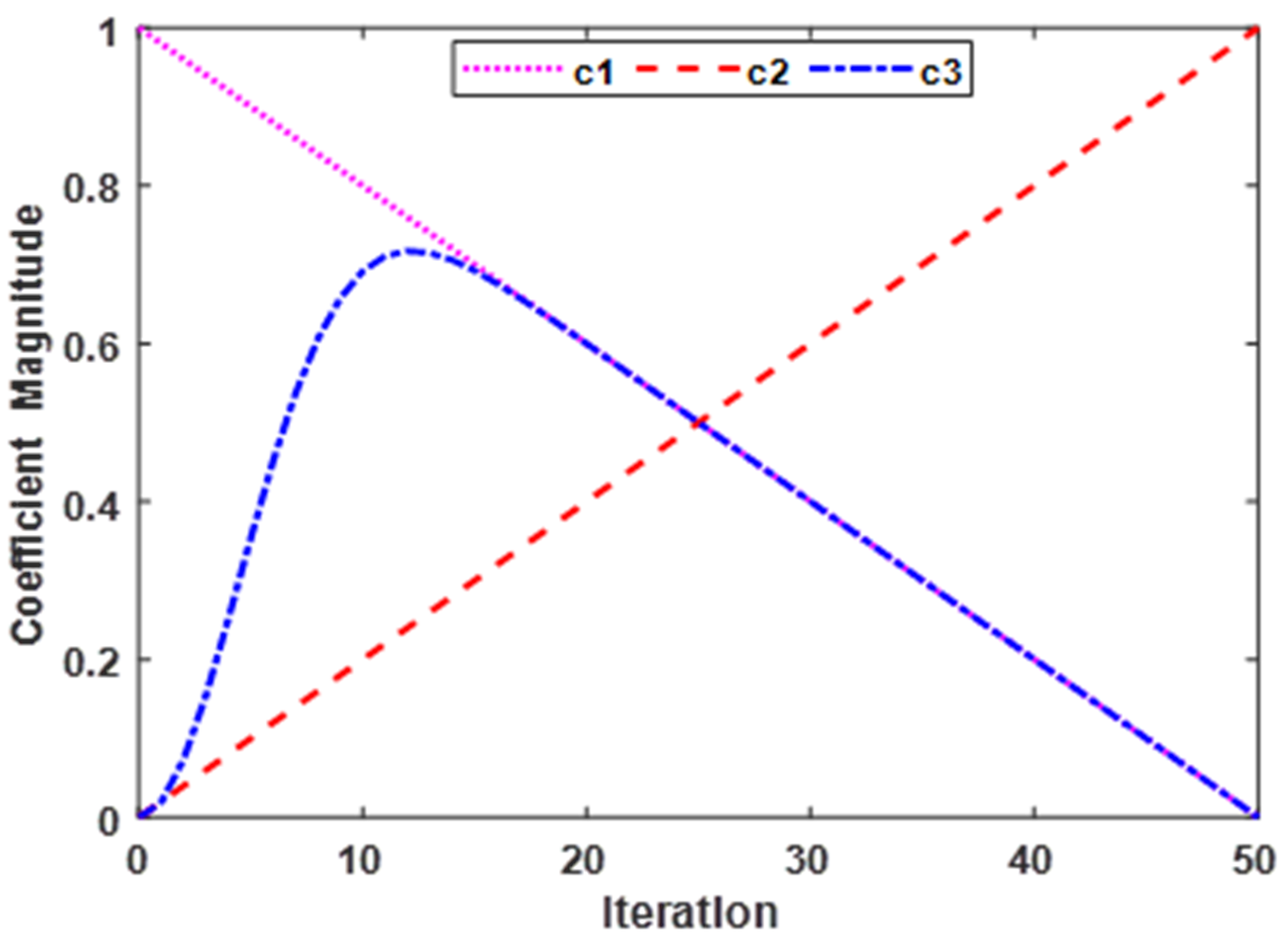
c 1 _ i n i t i a l and c 1 _ f i n a l are the initial and final values of the cognitive coefficient, respectively and c 2 _ i n i t i a l and c 2 _ f i n a l are the initial and final values of the social coefficient respectively. To observe the behaviour of all the acceleration coefficients (c1, c2, and c3) of the MPSO algorithm, their magnitudes are plotted against the iteration number as depicted in Figure 3.
For the current research work, the values for the c1 and c2 are varied from 1 to 0.2 and 0.2 to 1 respectively over 50 iterations. It can be seen from Figure 4. that the magnitude of the c 3 is increasing exponentially during the initial iterations which supports the particles in rapidly exploring the whole search space to acquire the best possible solution and avoid convergence to any local best position. On the other hand, the magnitude for the c2 is increasing linearly with increasing iterations to encourage particles to move towards the global best position (gbest). Thus, the exploration versus exploitation balance of the MPSO is maintained, consequently leading to improved solution quality and convergence rate.

3.2. MPSO Implementation in Developed Grid-Tied MG Model

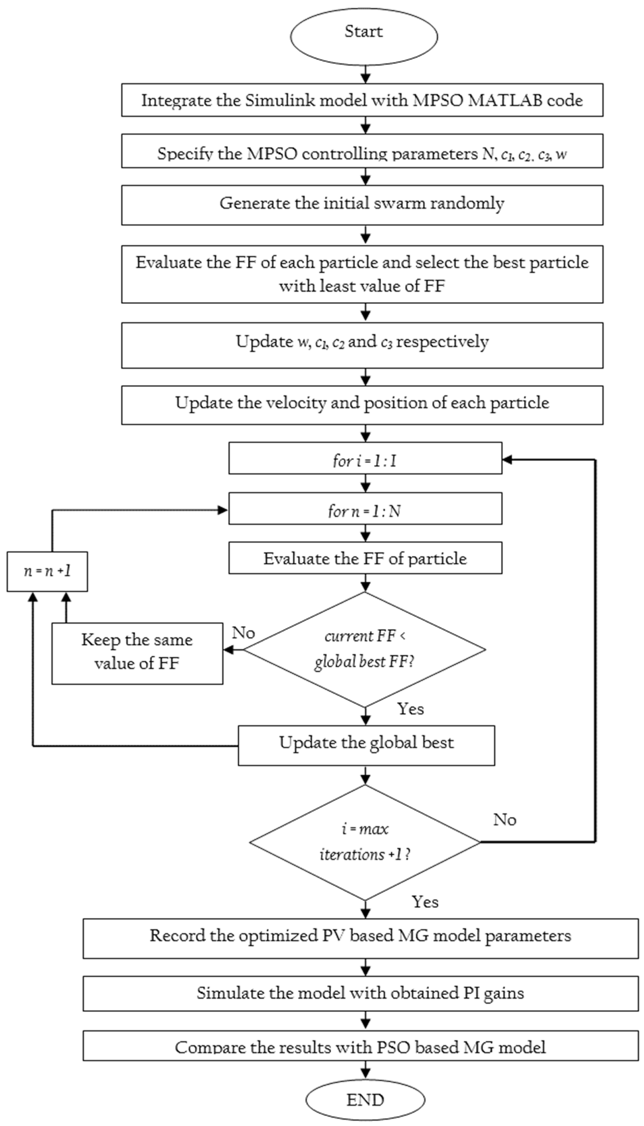
The complete flowchart of the proposed methodology for employing the MPSO algorithm in acquiring optimal parameters of the developed M.G. controller is shown in Figure 4.
The proposed MPSO code is implemented using the MATLAB editor window, while the model for the grid-connected M.G. was modeled in MATLAB/SIMULINK version 2018b. Owing to the superior performance and realistic outcomes, the integral time absolute error (ITAE) has been opted as the F.F. for the current study, as given in Equation (11).
F . F = M i n 0 t * e p d t + 0 t * e q d t
Before starting the simulation, the developed Simulink model is integrated with the MPSO MATLAB code using the “sim(‘file_name’)” built-in command. In addition, the number of iterations and particles is also pre-decided. During the first iteration of the simulation run, a bounded search space is created whose dimensions are decided by the number of decision variables. Since current research attempts to optimize the gains of two P.I. regulators used in the power control loop, the MPSO algorithm will create a 4-dimensional search space. The upper and lower bounds of the decision variables decide the boundaries of the respective dimension of the created search space. Once a bounded search space is created, the pre-decided number of search agents (particles) are disseminated randomly. During the simulation process, the ITAE value is calculated for each iteration and is sent to the MATLAB Workspace where the intelligence of MPSO is exploited to minimize its magnitude. Once the iterative process is completed, the optimal P.I. parameters are recorded and placed in their respective P.I. controller blocks in the developed M.G. Simulink model. Finally, the model is simulated to record the active and reactive power curves and to evaluate and compare their corresponding transient response based on overshoot and settling time as provided in the next section of this study. Afterward, the F.F. of each search agent is calculated and sorted in descending order according to their magnitudes. The position of the particle having the least value of F.F. will be selected as the global best. The remaining particles will update their position and velocity with reference to the position of the global best particle using Equations (9) and (10) respectively. After each successive iteration, the F.F. of each particle is evaluated, and the global best is updated accordingly. Finally, at the end of the simulation, the optimized values of the decision variables (Kpp, Kip, Kpq and Kiq) are obtained and inserted into their corresponding places in the Simulink model to obtain the most optimal response of the studied solar PV based M.G. model.
Since the F.F. minimization is taken as an optimization task, the most optimal transient response of the proposed grid-tied M.G. system corresponds to the least magnitude of the F.F. Therefore, the P.I. parameters where the ITAE provides minimum value will be selected for simulation purposes. Instead of manually selecting the optimal P.I. parameters by hit and trial, PSO and MPSO are utilized to carry out the mentioned task automatically. The code for both the algorithms along with the optimization parameters is written in MATLAB Editor, whereas the grid-tied M.G. along with the proposed control architecture and F.F. is incorporated into the MATLAB/Simulink version 2018b.

4. Results and Discussion

A gird-tied M.G. and a robust and intelligent controller are developed in MATLAB/Simulink version 2018b to simulate the behaviour of studied grid-connected M.G. under different operating conditions. The developed model is simulated for parameters as shown in Table 1.
The proposed M.G. controller is developed based on this study’s active-reactive (P.Q.) power control strategy. The MPSO algorithm searches the optimal P.I. parameters in the developed M.G. controller. To demonstrate the efficacy of the proposed MPSO-based M.G. control structure, its performance is compared with the PSO-based controller on similar operating conditions and optimization parameters. Furthermore, the upper and lower limits for all the optimized parameters are set in between 0 to 50 to limit the search space of PSO and MPSO so that both algorithms can effectively manage their searching mechanism. The number of particles and iterations is 50 for both PSO and MPSO algorithm. The performance of the proposed MPSO-based grid-tied M.G. is evaluated for the following three cases.

4.1. Power-Sharing Evaluation during D.G. Insertion and Abrupt Load Changes

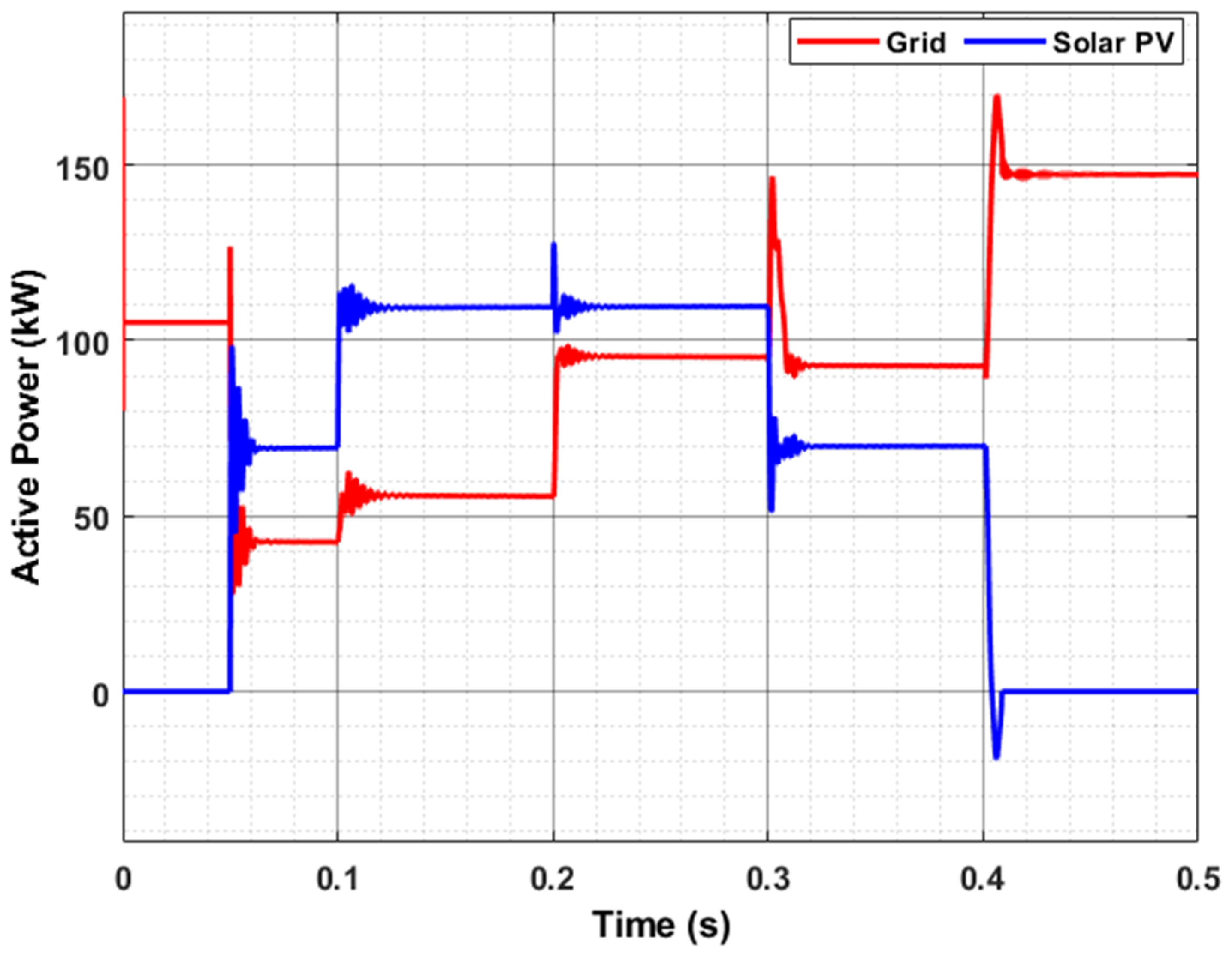
In order to observe and assess the performance of the proposed controller, the behavior of the developed MPSO-based M.G. system is analyzed during D.G. insertion and a step load change. To accomplish the mentioned objective, a D.G. with a set reference power of 70 kW and 40 kVAR is injected at 0.05 s of the simulation while two-step loads of 55 kW, 38 kVAR, and 40 kW, 18 kVAR are injected into the system at 0.1 s and 0.2 s respectively. The simulation is run for 0.5 s as per the following schedule.
Based on the operating conditions depicted in Table 2, the corresponding active and reactive power sharing between D.G. and utility grid of the grid-tied M.G. system is shown in Figure 5 and Figure 6, respectively.
It may be noted that the complete M.G. operation is made in a fraction of a second in order to realistically evaluate the performance of the developed system as the load switching in a real power system is entirely unpredictable and quick. It can be seen from Figure 6 and Figure 7 that the developed grid-tied M.G. system is exactly following the reference D.G. power values and switching schedule provided in Table 2. At the starting of the simulation, the complete load is supported by the grid and the M.G. is in off mode. At 0.05 s, a 120 kW solar PV is injected into the system to support the utility grid. It adopts 70 kW, 55 kVAR of the total load (110 kW, 38 kVAR) as per the set reference power, relieving the burden on the utility grid. Since the total reactive power load on the system at 0.05 s was only 38 kVAR while the injected reactive power from DG is 56 kVAR, the remaining power is provided to the utility grid which is evident from Figure 7 as it shows a negative value of reactive power from 0.1 to 0.2 s. At 0.1 s a load of 55 kW, 20 kVAR is injected into the system. Once again as per the set reference, the D.G. adopts 40 kW, 28 kVAR while the grid is shares only 10 kW, 0 kVAR. It is worth noting that the grid reactive power has changed from −10 kVAR to −18 kVAR during the mentioned time. This because of the reason that the D.G. is made to adopt 28 kVAR and the total additional reactive load was only 20 kVAR, hence the D.G. injected an additional 8 kVAR into the grid. At 0.2 s of the simulation run, a load of 40 kW, 18 kVAR is injected into the system. However, this time the D.G. does not contribute any power to the system as per the control designer choice. Hence the complete additional load is shifted to the grid as evident from Figure 6 and Figure 7. At 0.3 s, the Load-2 is abruptly detached from the system, consequently reducing the D.G.’s supplied power. Finally, at 0.4 s of the simulation, the solar PV is disconnected from the rest of the power system, thus the total load is shifted to the utility grid can be seen from the provided figures. From the above discussion, it is concluded that the proposed control grid-tied M.G. control architecture works perfectly fine under D.G. injection and abrupt load changes by achieving desired power-sharing ratio set by the control designer.

4.2. Comparison between PSO and MPSO-Based Control Designs

In this case, the PSO and MPSO methods have been tested and compared to minimize the objective function which is ITAE. The performance of the proposed controller is evaluated with two different P.I. control methods, namely, PI-PSO and PI-MPSO. The optimized parameters obtained at the end of the simulation are given in Table 3.
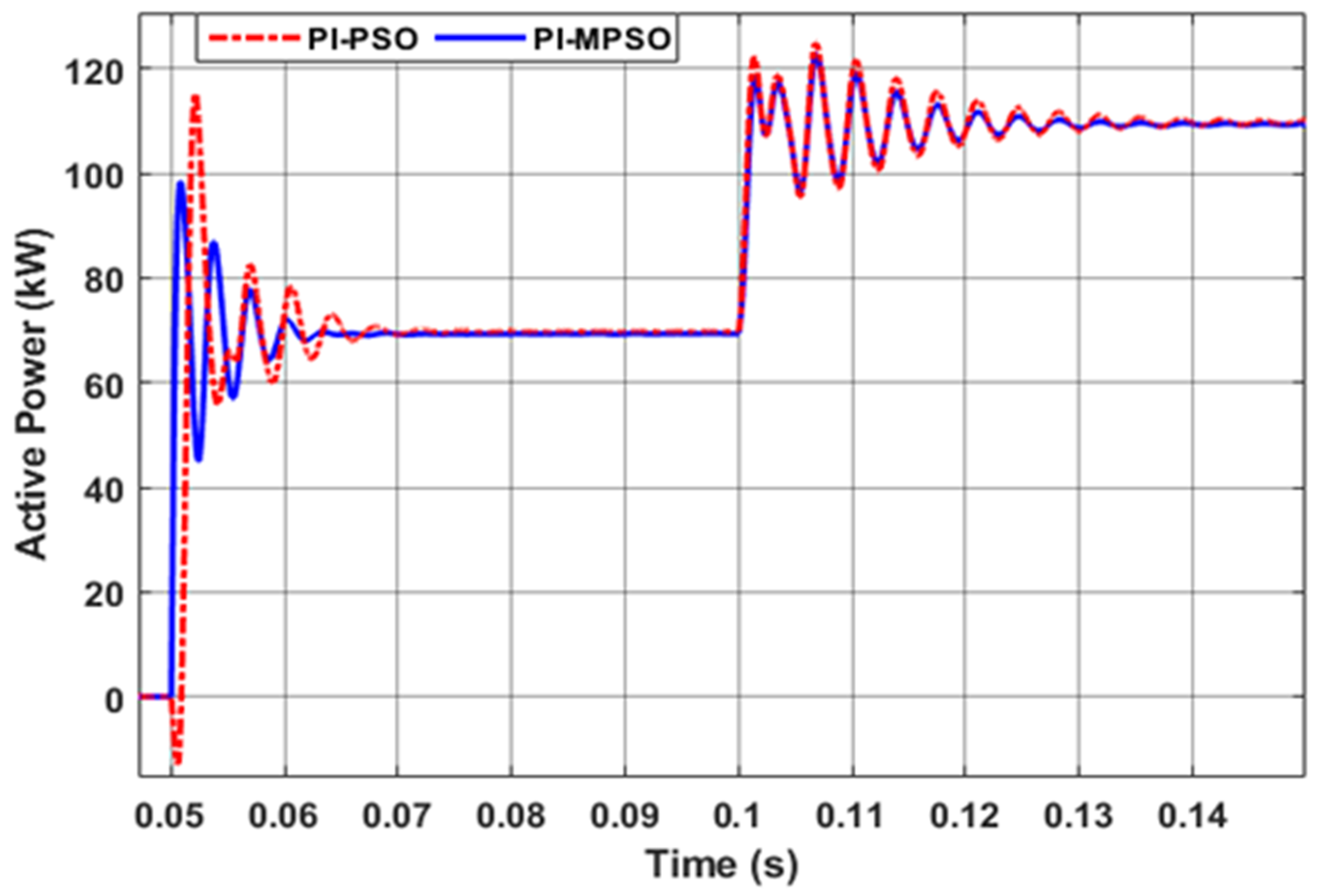
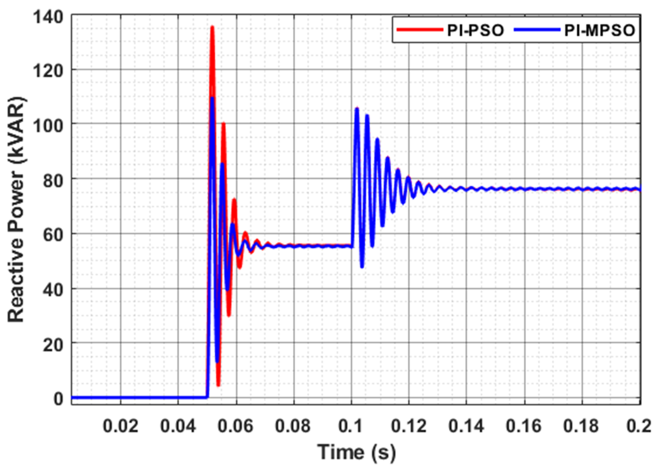
In Table 3, the Kpp and Kip represent the proportional and integral gain for the active power P.I. controller respectively while Kpq and Kiq represent the proportional and integral gain or the reactive power P.I. controller respectively. It is worthwhile to mention here that both PSO and MSPO algorithms are integrated with the developed grid-tied M.G. Simulink model individually and are made to run as an offline optimization process. Both the algorithms were run for an exactly similar number of iterations, and identical optimization parameters in order to carry out a fair comparison. Furthermore, the codes of both algorithms are executed for optimizing the M.G. parameters 10 times to avoid any errors due to the stochastic nature of the algorithms. Once the codes are executed for a set number of iterations (50), the displayed P.I. parameters are adopted from the MATLAB command window and are placed in their respective P.I. controller blocks present in the developed grid-tied M.G. Simulink model. At the start of the simulation, the main grid supplies the complete connected load. Afterward, at 0.05 s of the simulation run, D.G. is inserted into the system through a three-phase circuit breaker. Once the steady-state condition is reached, another load of 55 kW, 20 kVAR is injected at 0.1 s. The corresponding active and reactive power curves for both MPSO and PSO-based MG controllers are shown in Figure 8 and Figure 9 respectively.
As can be seen in Figure 7 and Figure 8 that the system observes overshoot and undershoot at the time of D.G. injection i.e., 0.05 s. For both PSO-PI and MPSO-PI-based MG models, the D.G. adopts the pre-set power ratio i.e., 70 kW, 55 kVAR which authenticates the proper functioning of the developed M.G. model. However, due to optimal parameter selection, the M.G. with MPSO-PI tuning provides a better transient response than its counterpart PSO-PI MG. Similarly, a load of 55 kW, 20 kVAR is injected at 0.1 s to evaluate the dynamic response of the studied M.G. models during a step load change condition. Once again, the MPSO-based parameter selection method outperforms its competitor by providing lesser overshoot and settling time; thus, it verifies the effectiveness of the proposed optimization method for the studied grid-tied M.G. system. In order to assess the improvement achieved in transient response by implementing the proposed MPSO-based MG controller, the obtained results from both PI-PSO and MPSOPI-based MG systems are evaluated based on two of the well-known transient response indicators i.e., percentage overshoot (%Mp) and settling time (ts). The results for the D.G. injection condition are tabulated in Table 4 while the same for the load change condition are presented in Table 5.
As can be seen from Table 4 and Table 5 that the proposed PI-MPSO-based M.G. controller outperforms the conventional PI-PSO-based controller in terms of overshoot and settling time during both D.G. injection and load change conditions. Hence it can be concluded that the proposed controller is better in obtaining the optimized dynamic response of the considered grid-connected M.G. than the conventional PSO-based controller for identical operating conditions.

4.3. Fitness Function Convergence Behavior

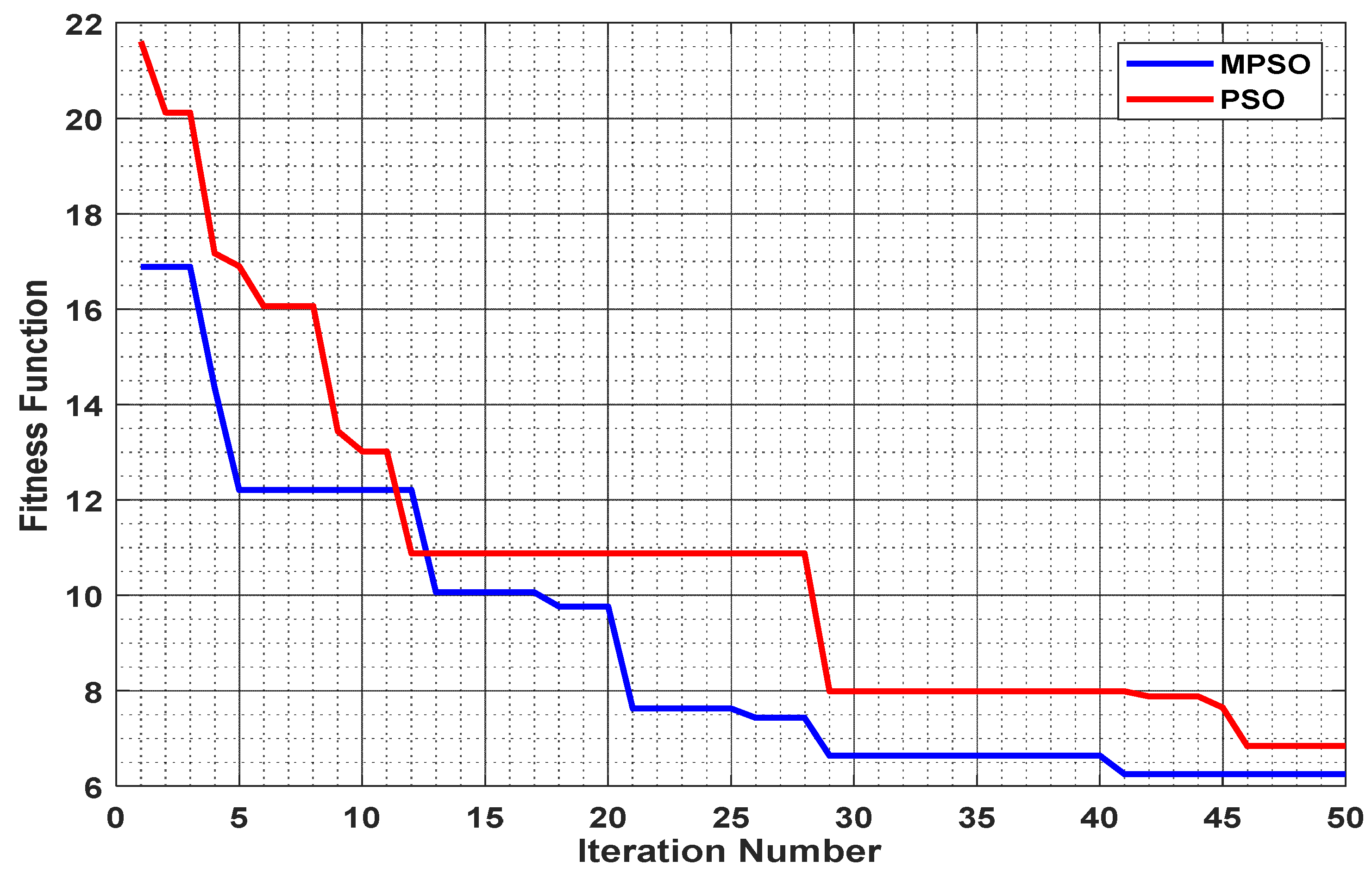
The convergence curve of any optimization technique shows how quickly an optimization technique can obtain a qualitative solution [7,15]. The greater the convergence rate of an optimization technique, the greater will be its ability to reach the final optimized values within a minimum number of iterations [18]. In this case, the ITAE minimizes as the F.F., PSO, and MPSO are inspected for minimizing the stated F.F.; the results are shown in Figure 9.
It can be seen from Figure 9 that the MPSO attains faster convergence than that of the conventional PSO which results in the most optimal design of the studied M.G. system. The PSO achieves an optimal value of the ITAE i.e., 6.8387 in 46 iterations while the MPSO achieves a better solution quality by minimizing the F.F. value to 6.2488 in 41 iterations. Hence it can be concluded that the MPSO provides a superior and faster optimization process compared to its conventional counterpart for the optimal design and dynamic response enhancement of considered grid-tied M.G.

5. Conclusions

This paper has presented an MPSO-based intelligent controller for transient response enhancement in a grid-connected M.G. system. The performance of the proposed power flow control architecture has been evaluated for different M.G. operating conditions like M.G. insertion and load change conditions. Furthermore, the system is tested for power-sharing ratios among solar PV and grid. The MPSO algorithm optimizes the P.I. controller parameters dynamically under all operating conditions. The main performance parameters are the overshoot and settling time for active and reactive power during solar PV insertion and load changes. Furthermore, the performance of the proposed controller has been compared with the conventional PI-PSO-based controller, which validates the effectiveness of the proposed control scheme. The proposed controller provides a percentage overshoot decrement in active and reactive power of 37.08% and 29.05% during solar PV injection, respectively while the same parameters were recorded as 31.93% and 20.10% for the settling time. The study’s outcomes prove that the proposed MPSO-based controller provides the most optimal design of the studied M.G. system by providing a reduced overshoot and settling time compared to its competitor PI-PSO-based M.G. design.

Author Contributions

All authors planned the study and contributed to the idea and field of information. All authors have read and agreed to the published version of the manuscript.

Funding

This work was supported by the National Natural Science Foundation of China (52150410399).

Data Availability Statement

Not applicable.

Conflicts of Interest

The authors declare no competing interests.

Abbreviations

D.G.Distributed Generation
MPSOModified Particle Swarm Optimization
PSOParticle Swarm Optimization
M.G.Microgrid
ITAEIntegral Time Absolute Error
F.F.Fitness Function
SVPWMSpace vector pulse width modulation
IGBTInsulated gate bipolar transistor
P.I.Proportional Integral
GAGenetic Algorithm
V.S.I.Voltage Source Inverter

References

  1. Jumani, T.A.; Mustafa, M.W.; Rasid, M.M.; Mirjat, N.H.; Leghari, Z.H.; Saeed, M.S. Optimal Voltage and Frequency Control of an Islanded Microgrid using Grasshopper Optimization Algorithm. Energies 2018, 11, 3191. [Google Scholar] [CrossRef] [Green Version]
  2. Aziz, S.; Peng, J.; Wang, H.; Jiang, H. ADMM-Based Distributed Optimization of Hybrid MTDC-AC Grid for Determining Smooth Operation Point. IEEE Access 2019, 7, 74238–74247. [Google Scholar] [CrossRef]
  3. Jumani, T.A.; Mustafa, M.W.; Rasid, M.M.; Mirjat, N.H.; Baloch, M.H.; Salisu, S. Optimal Power Flow Controller for Grid-Connected Microgrids using Grasshopper Optimization Algorithm. Electronics 2019, 8, 111. [Google Scholar] [CrossRef] [Green Version]
  4. Zhang, R.; Li, G.; Bu, S.; Aziz, S.; Qureshi, R. Data-driven cooperative trading framework for a risk-constrained wind integrated power system considering market uncertainties. Int. J. Electr. Power Energy Syst. 2023, 144, 108566. [Google Scholar] [CrossRef]
  5. Aziz, S.; Wang, H.; Liu, Y.; Peng, J.; Jiang, H. Variable Universe Fuzzy Logic-Based Hybrid L.F.C. Control With Real-Time Implementation. IEEE Access 2019, 7, 25535–25546. [Google Scholar] [CrossRef]
  6. Saeed, M.S.; Mustafa, M.W.; Sheikh, U.U.; Jumani, T.A.; Mirjat, N.H. Ensemble Bagged Tree Based Classification for Reducing Non-Technical Losses in Multan Electric Power Company of Pakistan. Electronics 2019, 8, 860. [Google Scholar] [CrossRef] [Green Version]
  7. Jumani, T.A.; Mustafa, M.; Rasid, M.M.; Anjum, W.; Ayub, S. Salp Swarm Optimization Algorithm-Based Controller for Dynamic Response and Power Quality Enhancement of an Islanded Microgrid. Processes 2019, 7, 840. [Google Scholar] [CrossRef] [Green Version]
  8. Arfeen, Z.A.; Kermadi, M.; Azam, M.K.; Siddiqui, T.A.; Akhtar, Z.U.; Ado, M.; Abdullah, M.P. Insights and trends of optimal voltage-frequency control DG-based inverter for autonomous microgrid: State-of-the-art review. Int. Trans. Electr. Energy Syst. 2020, 30, e12555. [Google Scholar] [CrossRef]
  9. Chung, I.-Y.; Liu, W.; Cartes, D.A.; Collins, E.G.; Moon, S.-I. Control methods of inverter-interfaced distributed generators in a microgrid system. IEEE Trans. Ind. Appl. 2010, 46, 1078–1088. [Google Scholar] [CrossRef]
  10. Eslami, M.; Shareef, H.; Mohamed, A.; Khajehzadeh, M. Coordinated design of PSS and SVC damping controller using CPSO. In Proceedings of the 2011 5th International Power Engineering and Optimization Conference, Shah Alam, Malaysia, 6–7 June 2011; pp. 11–16. [Google Scholar] [CrossRef]
  11. Habib, S.; Abbas, G.; Jumani, T.A.; Bhutto, A.A.; Mirsaeidi, S.; Ahmed, E.M. Improved Whale Optimization Algorithm for Transient Response, Robustness, and Stability Enhancement of an Automatic Voltage Regulator System. Energies 2022, 15, 5037. [Google Scholar] [CrossRef]
  12. Jumani, T.A.; Mustafa, M.W.; Hamadneh, N.N.; Atawneh, S.H.; Rasid, M.M.; Mirjat, N.H.; Bhayo, M.A.; Khan, I. Computational Intelligence-Based Optimization Methods for Power Quality and Dynamic Response Enhancement of ac Microgrids. Energies 2020, 13, 4063. [Google Scholar] [CrossRef]
  13. Khan, I.A.; Alghamdi, A.S.; Jumani, T.A.; Alamgir, A.; Awan, A.B.; Khidrani, A. Salp Swarm Optimization Algorithm-Based Fractional Order P.I.D. Controller for Dynamic Response and Stability Enhancement of an Automatic Voltage Regulator System. Electronics 2019, 8, 1472. [Google Scholar] [CrossRef] [Green Version]
  14. Jumani, T.A.; Mustafa, M.W.; Rasid, M.M.; Memon, Z.A. Dynamic response enhancement of grid-tied ac microgrid using slap swarm optimization algorithm. Int. Trans. Electr. Energy Syst. 2019, 30, e12321. [Google Scholar]
  15. Ali, A.; Abbas, G.; Keerio, M.U.; Koondhar, M.A.; Chandni, K.; Mirsaeidi, S. Solution of Constrained mixed-integer multi-objectiveoptimal power flow problem considering the hybridmulti-objective evolutionary algorithm. IET Gener. Transm. Distrib. 2022, 1–25. [Google Scholar] [CrossRef]
  16. Abbas, G.; Ali, B.; Chandni, K.; Koondhar, M.A.; Chandio, S.; Mirsaeidi, S. A Parametric Approach to Compare the Wind Potential of Sanghar and Gwadar Wind Sites. IEEE Access 2022, 10, 110889–110904. [Google Scholar] [CrossRef]
  17. Wu, Z.; Zhuang, Y.; Zhou, S.; Xu, S.; Yu, P.; Du, J.; Luo, X.; Abbas, G. Bi-Level Planning of Multi-Functional Vehicle Charging Stations Considering Land Use Types. Energies 2020, 13, 1283. [Google Scholar] [CrossRef]
  18. Eslami, M.; Shareef, H.; Mohamed, A.; Khajehzadeh, M. Damping controller design for power system oscillations using hybrid GA-SQP. Int. Rev. Electr. Eng. 2011, 6, 888–896. [Google Scholar]
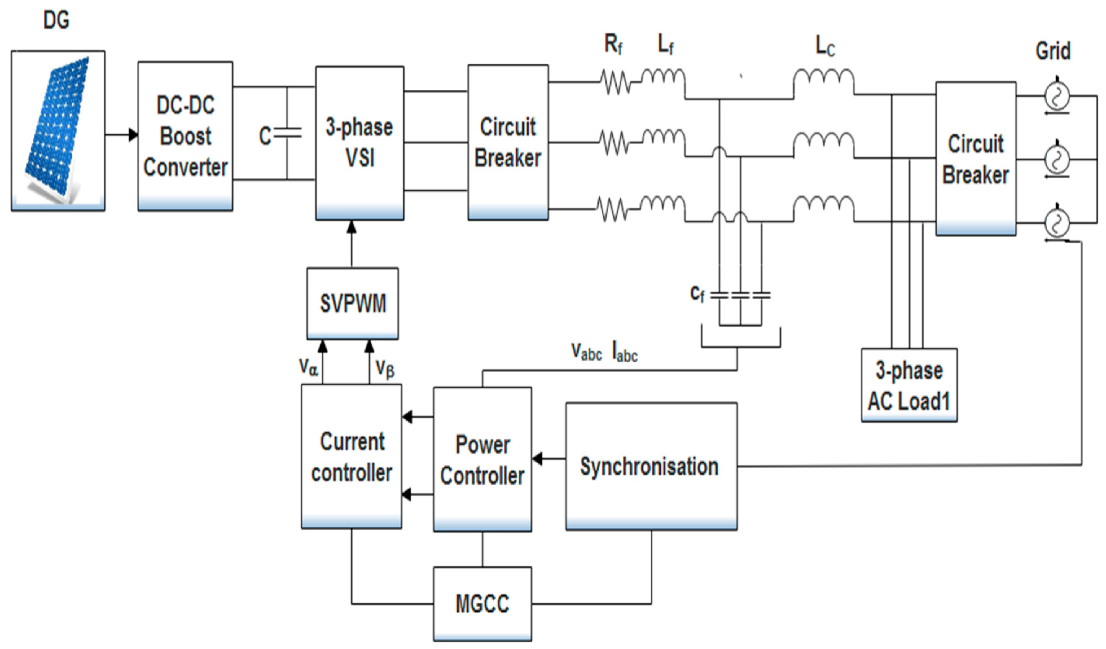
Figure 1. Three-phase Grid-Connected V.S.I. [7].
Energies 16 00348 g001
Figure 2. Proposed Power Control Strategy.
Energies 16 00348 g002
Figure 3. Behavior of acceleration coefficients during iteration.
Energies 16 00348 g003
Figure 4. Proposed Methodology.
Energies 16 00348 g004
Figure 5. Active power-sharing between the utility grid and D.G.
Energies 16 00348 g005
Figure 6. Reactive power-sharing between the utility grid and D.G.
Energies 16 00348 g006
Figure 7. Active power comparison.
Energies 16 00348 g007
Figure 8. Reactive power comparison.
Energies 16 00348 g008
Figure 9. Convergence Curve for PSO and MPSO.
Energies 16 00348 g009
Table 1. Studied M.G. Model Parameters.
Parameter NamesValue and Unit
DG rating120 kW
Load 1110 kW, 38 kVAR
Load 255 kW, 12 kVAR
Load 340 kW, 18 kVAR
DC link capacitor50 mF
R.L.C. Filter0.002 Ω, 0.63388 mH, 2500 µF
Switching frequency10 kHz
Sampling frequency500 kHz
Current controller P.I. gainsKp = 12.656, Ki = 0.00215
Table 2. Operating conditions and power-sharing between D.G. and utility grid.
Time (s)Operating ConditionTotal Load Injected or SharedD.G. Reference Power Values (Power Shared)Grid Shared Power
0–0.04Grid operation 110 kW, 38 kVAR0 kW, 0 kVAR110 kW, 38 kVAR
0.05 DG injection -70 kW, 55 kVAR40 kW, −10 kVAR
0.1Load insertion 55 kW, 20 kVAR 40 kW, 20 kVAR15 kW, 0 kVAR
0.2Load insertion40 kW, 18 kVAR0 kW, 0 kVAR40 kW, 18 kVAR
0.3Load detachment 55 kW, 12 kVAR55 kW, 2 kVAR0 kW, 10 kVAR
0.4DG detachment--147.5 kW, 68 kVAR
Table 3. Obtained optimized P.I. parameters.
Kpp KipKpqKiq
PI-PSO MG16.2736.65430.2505.839
MPSO-PI MG1.0889.65022.7692.150
Table 4. Transient response analysis for D.G. injection.
Active Power Reactive Power
% Mp ts (ms)% Mp ts (ms)
PI-PSO MG64.71 14.8146.9121.74
MPSO-PI MG40.7110.5100.017.37
% Improvement 37.0829.0531.9320.10
Table 5. Transient response analysis for load change.
Active Power Reactive Power
% Mp ts (ms)% Mp ts (ms)
PI-PSO MG13.6327.039.2127.1
MPSO-PI MG11.5420.039.4727.1
% Improvement 15.3325.920.660
Disclaimer/Publisher’s Note: The statements, opinions and data contained in all publications are solely those of the individual author(s) and contributor(s) and not of MDPI and/or the editor(s). MDPI and/or the editor(s) disclaim responsibility for any injury to people or property resulting from any ideas, methods, instructions or products referred to in the content.