Abstract
This paper introduces a novel waveguide intended for the spatial transfer of alternating magnetic fields. Instead of ferromagnetic material, an air core was proposed, while the cladding was realized using anisotropic metamaterial, built of the resonators and a paramagnetic composite. Since prior works regarding magnetic field transfer concentrated on static or high frequency fields, the proposed device complements the range of medium frequencies (several to hundreds of kilohertz). The three-dimensional model of the 50 cm long and 20 cm wide rectangular structure with metamaterial cladding was made in COMSOL and computed using the finite element method. Multi-turn inductors were considered and homogenized by the current sheet approximation, while an optimization solver was used to identify an optimal design of the waveguide. The analysis was made with respect to different resonators and permeability of the paramagnetic material. Additionally, the frequency response of the structure was determined. On these bases, the dependencies of the mean energy density and magnetic field intensity at the output of the waveguide were characterized. It was shown that discussed structure was able to provide an efficient transfer of the magnetic field between two ports. Thus, this device can be used to extend the distance of the wireless power transfer, especially between devices isolated by a thick barrier (e.g., wall), in which the meta-structure may be embodied.
1. Introduction
The progress in magnetic materials and metastructures had risen sharply in the last decade [1,2]. Due to the development of novel devices such as magnetic cloaks [3,4], concentrators [5,6], enhanced sensors [7] and artificial magnetic wormholes [8], new possibilities appeared. Nowadays one can improve the measurement range of magnetic field probes [9], simultaneously ensure the effective shielding and ‘hide’ objects [10], absorb power nearly perfectly in the energy harvesting systems [11] and minimize the influence of a device under test and an environment on each other [12]. Many extraordinary metamaterial properties were achieved through their ability to exhibit diamagnetic behavior and also due to anisotropy of the effective permeability and/or permittivity [13]. The well-thought usage of these attributes can lead to more efficient solutions and improvements of existing devices.
Since metamaterials are known for the static [14] and transient fields [15], the scope of interest and applications had expanded significantly. The most promising is the usage of metastructures in the wireless power transfer (WPT) to improve effectiveness [16], reduce the negative impact of a misalignment [17] and increase the distance of energy transfer [18]. For these purposes, one-, two- or three-dimensional metalenses were used. They are a combination of the resonators, i.e., planar inductors with a parasitic or lumped capacitance, resonating at a specific frequency [19]. The goal was to design the metamaterials with a near-zero effective permeability (if they were located behind the transmitting and receiving coils) or negative permeability (for the metamaterial located between the coils) [17,18]. In WPT studies, the enhancement of power transfer distance and efficiency are the two most important objectives. Therefore, it was proposed and studied to utilize the array of resonators [20] oriented horizontally [21,22] or perpendicularly [23] to the direction of an energy transfer. The idea may be found in transportation, where coupled resonators, placed below the surface, can transfer the power from a single source to several receivers distributed along the road [24]. As the result, the actual distance between the transmitter and receiver can be significantly extended. However, the exploration of similar metastructures operating in fast-varying fields and involving a range of frequencies from several to hundreds of kilohertz is still less expanded than the microwave or static magnetic field metamaterials.
In the low-frequency fields, the arrays of resonators cannot operate effectively, since the extremely high inductances and capacitances are necessary to achieve the resonance state. Therefore, in order to transfer the magnetic field through space, magnetic hoses were proposed [8,25,26]. A ferromagnetic core acted as a low-reluctance “path” for magnetic flux, whereas a diamagnetic shell (superconductor) preserved the magnetic flux from propagating outside the ferromagnetic interior. Although this composition was highly effective for the static magnetic field, the alternating field (e.g., operating in the kilohertz or megahertz band) will cause the eddy current inside the core, which leads to a power loss and attenuation. The superconductor was able to provide near-zero magnetic permeability, yet it required thermal insulation and a cooling system.
An alternative approach is to use the anisotropic metamaterial as a cladding of the waveguide, since meta-surfaces can obtain anisotropy of the effective properties with either negative or positive-negative values in, e.g., terahertz range [27], as well as simultaneously enhance the field intensity [28]. Both these properties are crucial in the design of the potential waveguide. In the GHz range, the dielectric resonator antenna, having a high gain and wide bandwidth, was synthesized using multi-layer stacks and changed into a cylinder possessing anisotropic permittivity [29]. The ferrite-filled rectangular waveguides were proposed as leaky-wave antennas [30], where two slots on the broad wall helped to improve the gain. This solution has led to further applications, such as integrated filters [31] proving that anisotropic structures can ensure several applications related to the transmission and conditioning of an electromagnetic (EM) signal.
In this paper, the magnetic hose for the medium frequency field was introduced. Compared to the high-frequency solutions, the presented waveguide has been intended for a medium frequency range. The ferrite filler was replaced by the air to eliminate the losses. In dielectric stacks, both the perpendicular and parallel components of permittivity can be negative [27], while it is important to note that the introduced waveguide ensures only a positive-negative combination of these components. What is more, the dielectric materials can be efficiently used when the propagation of the EM wave is considered, whereas in the magnetic fields the permittivity has a less contribution to the field distribution than the permeability. Hence, in the proposed solution, a dielectric shell can only serve as a frame mechanically supporting the structure, having a negligible impact on the effective properties. To compensate for the lack of a permittivity medium that controls the EM field propagation, the paramagnetic composite was used instead. Consequently, the idea of routing the static magnetic field (with the use of an anisotropic cladding) and the concept of the magnetically coupled array of resonators, had been combined into the anisotropic metamaterial, acting as the hose for transporting the magnetic field. The considered structure opens the possibility of the effective transfer of the alternating magnetic fields. In any application, increasing the distance of the magnetic field transfer is crucial, such as WPT through thick walls [32], magnetic resonance imaging [33,34] or in the distant magneto-resistive sensors [35], the hose operating in kilohertz range may become the solution. The article is organized as follows: in Section 2, the structure of the magnetic hose with metamaterial and the numerical model are shown; in Section 3, the parameters and results of numerical simulation are discussed, and the optimized constructions and the magnetic field distributions are presented; in Section 4, the most important conclusions are listed.
2. Materials and Methods
In this section, an overview of the introduced waveguide is presented. The structure is a combination of the magnetic hose for a static magnetic field and a microwave waveguide with a metamaterial cladding. Hence, the term “magnetic meta-hose” (MMH) was used in this study to distinguish the considered device from the two abovementioned. Additionally, the three-dimensional numerical model, used for the analysis of MMH, is characterized.
2.1. Structure of the Magnetic Meta-Hose
The design of the magnetic meta-hose was based on the single-layer hose [25], originally proposed and successfully tested for the static magnetic field. The non-static fields (i.e., electromagnetic waves) can be transferred by the classic waveguide. However, the transverse dimensions of the guide must be greater than the size of the wave. For example, an electromagnetic wave with a frequency of 100 kHz needs a waveguide with (approximately) 300 m wide input to propagate inside. To overcome some disadvantages of hoses and waveguides, the indirect structure can be used. An air was proposed instead of the ferromagnetic core and the superconducting shell was replaced by the anisotropic metamaterial cladding (Figure 1a). To ensure a similar effect to the one observed in the magnetic hose, the cladding was made of stacked resonators and the paramagnetic composite. As the result, resonators were able to mimic the effect of a near-zero permeability, while the paramagnetic hybrid composite introduced a higher permeability (µm) than the core (µcore = 1) to compensate for the absence of a low-reluctance path. It is important that the hybrid composite is characterized by the low value of the imaginary part of the permeability, resulting from a high surface resistivity [36], and thus the electromagnetic loss is vastly reduced in the kilohertz range.
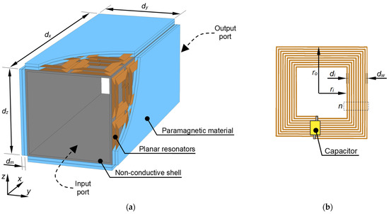
Figure 1.
Structure of the medium frequency magnetic meta-hose: (a) the source of the magnetic field should have been placed near the input port, while the resulting transfer of the magnetic field is observed at an output port. (b) A single resonator.
The inner shell of MMH was made of a non-conductive (and non-magnetic) material and operated only as a frame, at which the resonators and the composite were mounted. The length of the hose was dx, the width was dy and the height was dz. Throughout the research, it was assumed that dx = 2.5dy and dy = dz. The composite and resonators were stacked alternately, where the thickness of the composite layer was dm. The number of layers can be changed, although fewer layers are expected to decrease the efficiency of MMH, whereas more layers will lead to the extensive construction of the side walls.
Resonators were proposed as the square planar coils with outer size 2ro and inner resection 2ri (Figure 1b) and were wound using ultra-thin wires with a diameter of dw and an insulation thickness of di (the number of turns was n). This approach may help to ensure as high inductance as possible since many turns can be used at the limited surface of the planar inductor. Furthermore, to achieve a specific resonant frequency, the identical capacitors were connected in series with each coil. Their capacitance was adjusted during an optimization process.
The lumped parameters of planar inductors can be expressed by analytical formulae; however, they are valid for an isotropic and non-magnetic environment. A self-inductance of the planar coil is [37]
where c1, c2, c3, c4 are coefficients specific to the different shapes of inductor, e.g., a square, circular, octagonal, etc. [37]. A mean diameter is
while a fill factor is defined as
and an inner resection is expressed as
In Equation (1), the relative permeability (µr) of the surrounding area occurs. However, its value for the mixed type of environment (i.e., the air and layers of paramagnetic composite), is non-linearly dependent on an amount of paramagnetic material with a permeability of µm; hence, 1 < µr < µm. To identify µr or L for the different amounts of paramagnetic material, extra experiments or numerical calculations would be required. Nevertheless, Equations (1)–(4), even for µr = 1 and the imposed operating frequency (fr) of the external magnetic field, can still be useful to estimate an initial capacitance as
which was used as a starting point for the optimization process.
2.2. Metamaterial Properties
The anisotropic metamaterial is characterized by the complex effective permeability tensor (if the non-diagonal elements are omitted) [13]
where at least one component μx, μy or μz has a value that is different from the two others. In the case of a typical approach without the additional paramagnetic or ferromagnetic material, according to magnetic field components in Figure 2, the meta-cell simply possesses μx = μy = 1 and some complex permeability μz ≠ 1. The value of μz component is the result of an adjustment of the geometrical parameters of the inductor and the series capacitance [38].
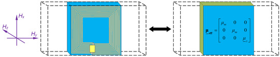
Figure 2.
An exemplary cell of the considered anisotropic metamaterial: the meta-cell acts as an anisotropic, homogenous medium characterized by the complex effective permeability tensor µeff.
By an application of the paramagnetic composite and limiting the thickness (z-axis) of the meta-cell to the thickness of the composite (dm), the effective permeability is
where μz also depends on μm. Still, it is possible to achieve the near-zero or negative real part of μz. To estimate its value, numerical computations need to be conducted since available analytical formulae are limited to cases where μm = 1 [38,39].
2.3. Simulation Model
The three-dimensional (3D) numerical model of MMH was created in COMSOL Multiphysics software, as shown in Figure 3. During simulations, only a quarter of the hose was represented due to symmetry of the system. The Magnetic Insulation boundary condition [40]
was assigned to an external xz surface, and the Perfect Magnetic Conductor boundary condition [40]
was used on xy boundary of the model. where n0 was the normal vector to the xy surface, A was the magnetic vector potential and H was the magnetic field. The Magnetic Insulation was also applied on the remaining external surfaces to imitate an expansive space outside the model, where the magnetic field tends to zero (isotropic, dielectric background). The infinitely long and negligibly thin conductor with the current I, located at a distance dI = ro from an input port, was the source of the external magnetic field. The ports were interpreted as surfaces at the beginning and the end of MMH. On these surfaces, magnetic field and magnetic energy were then examined.
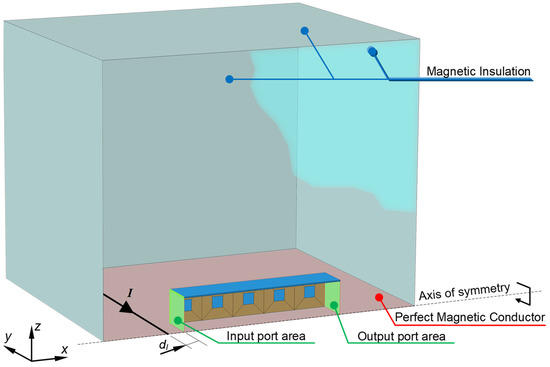
Figure 3.
Numerical model of the magnetic meta-hose with a line conductor as the source of the magnetic field. The model was analyzed as a quarter of the original structure, and symmetry conditions were applied on the external xz and xy surfaces.
The multi-turn planar inductors were modeled using the current sheet approximation approach [41,42,43], known in the COMSOL software as the Multi-turn coil boundary condition [44]. Many turns (nearly 200) and thin wires (dw << ro) must be imitated, leading to an undesirably high number of degrees of freedom. To reduce the memory demand of a computational unit, each coil was homogenized to four ‘sheets’, characterized by parameters such as the number of turns (n), an electrical conductivity (σw), a winding cross section (aw), and the total diameter of the wire (di + dw). Additionally, a lumped capacitor (C) was connected in series.
The system was analyzed in the frequency domain with angular frequency ω, with respect to the magnetic vector potential (A). The external current density Je = f(I) acted as the magnetic field source. The Helmholtz equation was used to find A and the magnetic field (H) [45]
Within the domains characterized by the known magnetic permeability (µ) and the electrical conductivity (σ). These parameters, the homogenized inductors, Equations (8)–(11) and the line current source I = 1 A were sufficient to describe the electromagnetic phenomena in the model and find the distribution of magnetic field (H). The system was solved numerically using the finite element method (FEM) [41,46], where the number of degrees of freedom resulting from a finite element mesh was around 500,000.
3. Results and Discussion
The magnetic meta-hose was analyzed for frequencies from 10 kHz to 1 MHz. The parameters of resonators and a nonconductive shell were presented in Table 1. To make the study more general, the fill factor (ν) was used instead of the number of turns (n) to show the influence of the inductor on the magnetic field transfer. The second variable was the relative magnetic permeability (µm) of a composite. Two operating frequencies were considered: fr = 25 kHz and fr = 100 kHz, to show the dependability and effectiveness of the system on the frequency of an external magnetic field.

Table 1.
Parameters used during simulations.
Since the magnetic field was considered in the study, the related quantities were calculated. To show the increase in the magnetic energy at the output port, the gain of energy transfer was calculated as
while the ability to preserve the high value of the magnetic field was defined as a ratio between the mean magnetic field at the output port and the input port
where Sin is the area of the input port, Sout is the area of the output port, |H0| is the magnetic field norm at the output port without MMH and |Hν,µm| is the magnetic field norm at the output port with MMH, characterized by the fill factor ν and the composite with relative permeability µm. Hence, η and k were calculated with respect to ν and µm.
The capacitor establishes a resonant frequency of the metamaterial; thus, a precise adjustment of the capacitance was necessary. To automatize this process, the optimization algorithm (Nelder-Mead method) was utilized. The algorithm was conjugated with the numerical model and its task was to maximize the one-dimensional objective function η = f(C). Therefore, the following procedure was realized:
- (1)
- Start from ν = 0 and µm = 1.
- (2)
- Estimate the inductance (L) using Equations (1)–(4).
- (3)
- Estimate the initial capacitance (C0) using Equation (5).
- (4)
- Run the simulation and optimization algorithm.
- (5)
- Adjust the capacitance during the optimization process to find the maximum η.
- (6)
- Stop and save the magnetic field distribution after identification of max(η).
- (7)
- Increase ν. If ν > 0.9 then increase µm and set ν = 0.
- (8)
- Execute points (2)–(7).
As the result, at a certain point (ν, µm) only optimized values of C and η were saved, while k was calculated. The exemplary values of optimized capacitances were listed in Tables S1 and S2 in the Supplementary Material.
3.1. Optimum Cases for Different Parameters of Metamaterial
After performing the optimization process, the maximum values of magnetic energy gain, i.e., max(η(ν, µm)) and corresponding magnetic field ratio k(ν, µm) were saved. Then, from the entire set of results, the best cases were found. On these bases it was possible to identify a structure of a coil (ν) and properties of composite (µm) which ensured the most efficient MMH for fixed geometrical parameters of the hose.
At the operating frequency fr = 25 kHz, the maximum energy gain ηbest = 1260.5 was found for ν = 0.15 and µm = 150, as shown in Figure 4a. Compared to the case without any hose, the energy density increased more than three orders of magnitude. For µm = 1 and different inductors (dashed red line in Figure 4a), the best energy gain was η = 26.86 (ν = 0.29). While for different permeabilities (without resonators), it was less than η = 1.7 (µm = 150). The differences in ηbest shows that it is unlikely to achieve the high energy gain using only resonators or paramagnetic/ferromagnetic material. However, by combining these two approaches, at some specific point, the gain can be elevated significantly. A similar situation was found with the magnetic field ratio k, where the best case kbest = 0.39 was identified for ν = 0.45 and µm = 26, and an area of high values of k in Figure 4b was much wider than in Figure 4a. This suggests that the magnetic field transfer “from input to output” of MMH can be achieved with many combinations of ν and µm. Nevertheless, the utilization of resonators (k = 0.32) or the composite material (k = 0.01) gave poorer results than their combination.
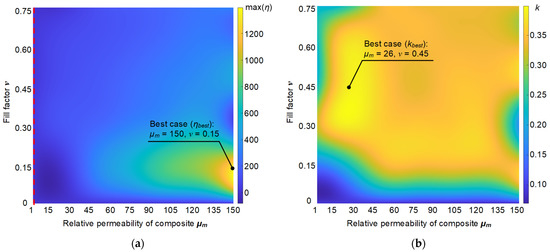
Figure 4.
The results of maximizing objective function η = f(C) for different fill factors ν and permeabilities µm at fr = 25 kHz: (a) energy transfer gain η and (b) magnetic field ratio k.
For fr = 100 kHz, the gain and ratio increased, as shown in Figure 5. The best case ηbest = 8466 (nearly 7 times higher than at fr = 25 kHz) was found for ν = 0.15 and µm = 124. At this time the highest assumed value of µm (i.e., 150) was not required to maximize the gain. While the fill factor ν for 25 kHz and 100 kHz, respectively, was 0.15 which (in this model) suggests that a large number of turns was not necessary to maximize a magnetic coupling. It is worth noting that more turns will increase the inductance and resistance, and hence after some ν, the quality factor Q = ωL/R starts decreasing, limiting the effectiveness of the magnetic energy transfer. What is more, the highest ratio kbest = 1.15 was found again for ν = 0.45 and µm = 26 and shows a possibility of not only transferring the magnetic field with no attenuation but also an ability to enhance it at the end of the hose. Comparing to fr = 25 kHz the area of high values of k (yellow parts) had changed. Here, the number of turns of inductors may have a more substantial impact on transferring the magnetic field from the input to the output of MMH than the permeability of the composite material.
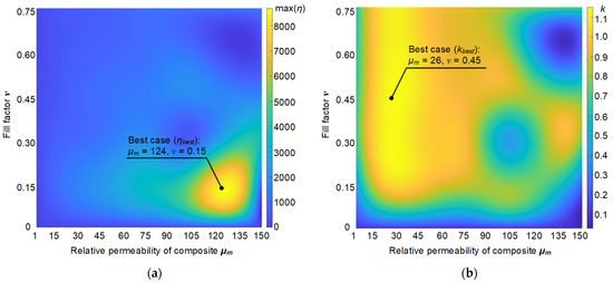
Figure 5.
The results of maximizing objective function η = f(C) for different fill factors ν and permeabilities µm at fr = 100 kHz: (a) energy transfer gain η and (b) magnetic field ratio k.
3.2. Magnetic Field Distribution
To show the effect of the magnetic field transfer, the distribution of |H|, in the best cases, was shown in this section. In the beginning, the cases without any hose and only with paramagnetic cladding were calculated. Additionally, the power flow was shown.
For the line current source in Figure 6, that is, an infinitely thin conductor, the magnetic field distribution has a typical shape. The magnetic field around the source has the highest values, while with growing distance, the magnetic flux tends to zero. The power flow was directed outside the conductor; hence, the field propagates to a distant space. In this case, the mean magnetic field norm (≈0.46 A/m) and the energy density (≈2.9 nJ/m) at the distance ro + dx (the output of MMH) were negligible, and at the distance ro (the input of MMH), their values were 7 A/m and 361 nJ/m, respectively. The situation changed after applying the composite material with µm = 150, as shown in Figure 7. However, at the output, the mean magnetic field was reduced (0.44 A/m) while the magnetic energy increased (4.9 nJ/m). As the result, the paramagnetic material was not able to achieve the task of transferring the magnetic field. The only visible effect on the magnetic field distribution was the change in the curvature of isolines at the input port of the hose. The magnetic flux had been ‘drawn’ into the hose, but the effective distance of the transfer was less than ro.
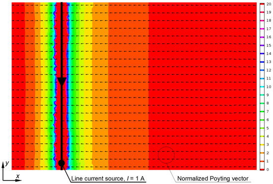
Figure 6.
Magnetic field norm (color) and normalized power flow (black arrows) for the model without the magnetic meta-hose.
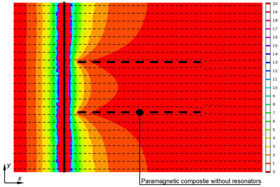
Figure 7.
Magnetic field norm (color) and normalized power flow (black arrows) for the model with the paramagnetic cladding (the highest considered permeability, μm = 150) without resonators.
Identical values and distributions were observed for both 25 and 100 kHz, due to the lack of conductive material in the system and no dispersion of permeability.
Comparing Figure 7 with Figure 8, the differences in the magnetic field distribution are clearly visible. At fr = 25 kHz, the magnetic flux was ’pulled’ in the MMH which can be noticed as an orange area (1 ÷ 4 A/m) inside the hose. The highest magnetic field in the hose was found in the resonators and the composite material. The Poyting vectors showed that the power traveled across the shell and then returned to an air core. Additionally, a kind of the power circulation can also be observed near the conductor (in Figure 6 the vectors were directed from the conductor to the outside space). The meta-hose visibly changed the magnetic field distribution and the power flow. This helped to achieve the increase in the magnetic field norm at the output (1.37 A/m) and magnetic field energy density (992 nJ/m). Although the magnetic flux had not reached the value initially found at the input port (7 A/m), the magnetic energy gain was significant.
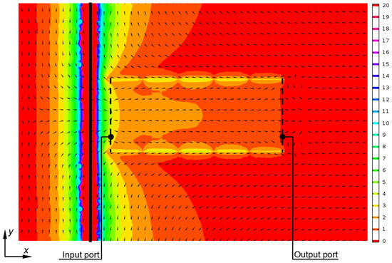
Figure 8.
Magnetic field norm (color) and normalized power flow (black arrows) for the best model with the magnetic meta-hose (ν = 0.15, µm = 150) at fr = 25 kHz.
Further observations regarding the spatial distribution of the magnetic field come from Figure 8, Figure 9 and Figure 10. A higher magnetic field can be observed around the centrally located resonators than the field around resonators closer to the source. This was probably due to the induced current inside the coils, which also was the highest in central inductors (e.g., for the waveguide in Figure 10, the current of the central coil was 3.95 mA, while the current of the coil at the input port was 1.59 mA). Furthermore, the ‘reversed’ power flow in the center of the hose appeared. Numerical calculations indicated that the power density inside MMH, mostly near the input port, was greater than in the surrounding space. This confirmed the effect of ‘pulling’ the field and energy into the hose. The changed direction of the Poyting vector arises, most probably, from the metamaterial cladding. In these examples, the interior of the magnetic hose acted as another metamaterial medium (with a negative refractive index), changing the direction of the x-component of the Poyting vector.
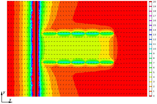
Figure 9.
Magnetic field norm (color) and normalized power flow (black arrows) for the best model with the magnetic meta-hose (ν = 0.15, µm = 124) at fr = 100 kHz.
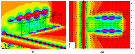
Figure 10.
Magnetic field norm (color) and normalized power flow (black arrows) for the model with the highest k = 1.15, i.e., the magnetic meta-hose (ν = 0.45, µm = 26) at fr = 100 kHz: (a) 3D view on the system with xz and xy cut planes and (b) 2D view on xy cut plane.
At fr = 100 kHz, as shown in Figure 9, the enhancement of the mean magnetic field at the output was more effective (≈5.7 A/m), and the magnetic energy reached the highest gain (3.64 µJ/m). It can also be noticed that the field was nearly uniform across MMH, with values of 4 ÷ 5 A/m, and transferred to the end of the hose. The power flow was similar to those in Figure 8. The last example in Figure 10 shows the magnetic field distribution for the case with the maximum k. The mean magnetic field at the output port reached nearly 8 A/m. While the magnetic flux was transferred effectively inside the air core, the field of centrally located resonators was almost as high as the one near the line conductor. The effect can be observed better in the 3D projection in Figure 10a.
3.3. Frequency Response of MMH
The frequency responses of the magnetic meta-hose were calculated to study their ability to enhance the magnetic energy transfer at the medium frequency range. Only the best cases from Section 3.1 were analyzed. As shown in Figure 11, the hose with the highest gain at fr = 25 kHz (η = 392.11) achieved a nearly identical value at f = 112.2 kHz (η = 318.24), while at f = 84.14 kHz, the gain was even higher (η = 417.03).
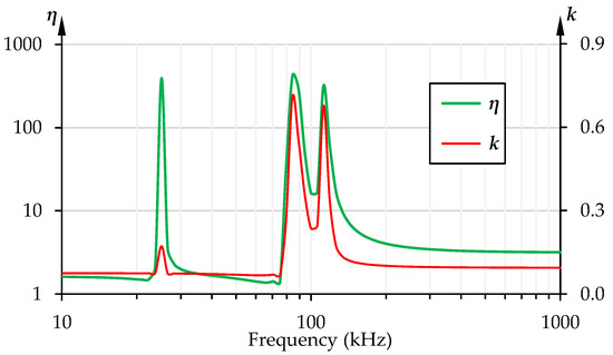
Figure 11.
Frequency response of the magnetic meta-hose with the highest energy transfer gain η (ν = 0.15, µm = 150) identified at fr = 25 kHz.
This example shows that MMH acts as a band-pass filter, able to transfer the magnetic energy for the designed frequency (e.g., 25 kHz) and simultaneously in the higher frequencies range. It was also confirmed by the magnetic field ratio k, which reached the highest values (for the abovementioned frequencies) with the peak k = 0.71 at f = 84.14 kHz (more than four times higher than k = 0.172 at f = 25 kHz). In Figure 11 and Figure 12, it can be seen that obtaining the optimal gain at some imposed frequency will not exclude the possibility of the effective magnetic field transfer at the other (higher) frequencies.
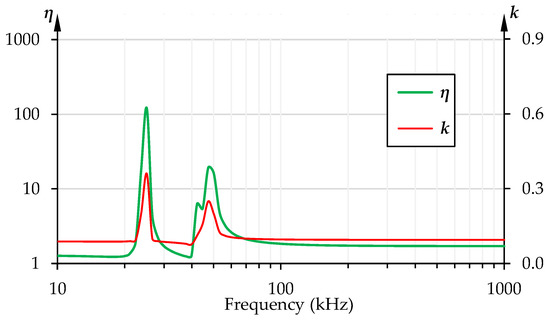
Figure 12.
Frequency response of the magnetic meta-hose with the highest magnetic field ratio k (ν = 0.45, µm = 26) identified at fr = 25 kHz.
The results were much more promising for the operating frequency fr = 100 kHz, shown in Figure 13. The gain η was nearly 8466.06 (f = 100 kHz) and 594.75 (f = 316.23 kHz) as well as 1107.29 (f = 421.7 kHz), which was at least an order of magnitude more than the values observed for fr = 25 kHz. The high values of η were also accompanied by the elevated values of k. The imposed frequency fr = 100 kHz allowed us to achieve k = 0.715 and, similar to the previous cases, two additional peaks were found where k was more significant. For f = 316.23 kHz the magnetic field ratio exceeded 1, which means the magnetic field was amplified at the output (compared to the magnetic field at the input).
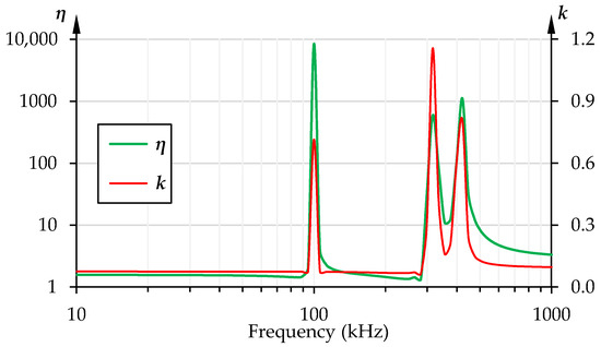
Figure 13.
Frequency response of the magnetic meta-hose with the highest gain of energy transfer η (ν = 0.15, µm = 124) identified at fr = 100 kHz.
In Figure 14, the frequency response of MMH with the highest recorded k at fr = 100 kHz was presented. The same observations can be made in Figure 12. In the considered frequency range, the highest gain and ratio were found at the imposed frequency of 100 kHz, and two subsequent peaks were nearly combined. By analyzing Figure 10, Figure 11, Figure 12 and Figure 13 one may conclude that magnetic meta-hose was able to act as a spatial band-pass filter for the transient magnetic field. The passed frequencies can be adjusted, for instance, by changing the parameters of the inductors and the capacitor.
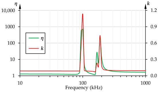
Figure 14.
Frequency response of the magnetic meta-hose with the highest magnetic field ratio k (ν = 0.45, µm = 26) identified at fr = 100 kHz.
The analyzed cases indicated that MMH led to greater values of energy density gain and magnetic field ratios with higher operating frequencies. However, for the frequencies over 1 MHz some negative effects, such as the eddy currents, dispersion, and a magnetic loss in a composite material will be observed, leading to a reduced ability of MMH to transfer the magnetic field and/or electromagnetic waves effectively. The practical frequency range of the proposed magnetic hose will probably be located between several dozen to several hundred kilohertz. Furthermore, it was not a rule that optimum cases for η also provided the highest k. Figure 11 and Figure 13 revealed that the peak values of the magnetic field ratio were found at higher frequencies than fr.
4. Conclusions
The paper concentrated on an analysis of the magnetic meta-hose intended for the transfer of the medium frequency magnetic field. The structure of the device was proposed as a hybrid between the magnetic hose for the static field and the classic waveguide. The anisotropic metamaterial was introduced as a cladding of the waveguide to ensure a propagation of the magnetic field along the specified path. Two layers of the planar resonators and a paramagnetic composite were used to form the metamaterial. Due to the layered construction of the hose, it was possible to reduce the thickness of the walls and utilize an air core which combined, accordingly minimizing the mass of the device.
The numerical model of the meta-hose was created, and the magnetic field distribution was calculated. The results showed that the proposed meta-structure was able to transfer the magnetic field and its energy at the considered distance effectively. The magnetic energy density was increased more than a thousand times at a lower frequency (25 kHz) and more than eight thousand times at 100 kHz. For the second operating frequency, the mean magnetic field norm at the output of the magnetic hose was not lower than at the input, and hence the task of transferring the magnetic flux had been achieved. Furthermore, the frequency characteristics demonstrated a band-pass behavior of the magnetic meta-hose since only signals with the specific frequencies were transferred. This property is similar to the one exhibited by optical fibers, where only some modes of the electromagnetic field, at particular frequencies, can propagate across the waveguide.
Although the numerical results were promising, a comparison with the experimental measurements is essential. The verification would require a prototype of the magnetic meta-hose and to test the power transfer efficiency from some magnetic field source to a load (e.g., a receiving coil). The advantage of the introduced structure is the set of commercially available components (dielectric frames, thin wires and paramagnetic composites); hence, the proposed magnetic hose can be manufactured with current technologies.
Supplementary Materials
The following supporting information can be downloaded at: https://www.mdpi.com/article/10.3390/en16010334/s1, Table S1: Optimized capacitances in (nF) resulting from the Nelder-Mead algorithm used for the design of a magnetic meta-hose, intended to operate in the external magnetic field at fr = 25 kHz; Table S2: Optimized capacitances in (nF) resulting from the Nelder-Mead algorithm used for the design of a magnetic meta-hose, intended to operate in the external magnetic field at fr = 100 kHz. Tables with exemplary optimized capacitances.
Funding
This research was funded by the Ministry of Science and Higher Education in Poland at the Bialystok University of Technology under research subsidy No. WZ/WE-IA/2/2020.
Data Availability Statement
Not applicable.
Acknowledgments
Not applicable.
Conflicts of Interest
The authors declare no conflict of interest.
References
- Elahi, E.; Dastgeer, G.; Nazir, G.; Nisar, S.; Bashir, M.; Qureshi, H.A.; Kim, D.-K.; Aziz, J.; Aslam, M.; Hussain, K.; et al. A review on two-dimensional (2D) magnetic materials and their potential applications in spintronics and spin-caloritronic. Comput. Mater. Sci. 2022, 213, 111670. [Google Scholar] [CrossRef]
- Ali, A.; Mitra, A.; Aïssa, B. Metamaterials and Metasurfaces: A Review from the Perspectives of Materials, Mechanisms and Advanced Metadevices. Nanomaterials 2022, 12, 1027. [Google Scholar] [CrossRef] [PubMed]
- Jiang, W.; Ma, Y.; Zhu, J.; Yin, G.; Liu, Y.; Yuan, J.; He, S. Room-temperature broadband quasistatic magnetic cloak. NPG Asia Mater. 2017, 9, e341. [Google Scholar] [CrossRef]
- Zhu, J.; Jiang, W.; Liu, Y.; Yin, G.; Yuan, J.; He, S.; Ma, Y. Three-dimensional magnetic cloak working from dc to 250 kHz. Nat. Commun. 2015, 6, 8931. [Google Scholar] [CrossRef]
- Navau, C.; Prat-Camps, J.; Sanchez, A. Magnetic Energy Harvesting and Concentration at a Distance by Transformation Optics. Phys. Rev. Lett. 2012, 109, 263903. [Google Scholar] [CrossRef]
- Sun, F.; He, S. Static magnetic field concentration and enhancement using magnetic materials with positive permeability. PIER 2014, 142, 579. [Google Scholar] [CrossRef]
- Navau, C.; Mach-Battle, R.; Parra, A.; Prat-Camps, J.; Laut, S.; Del-Valle, N.; Sanchez, A. Enhancing the sensitivity of magnetic sensors by 3D metamaterial shells. Sci. Rep. 2017, 7, 44762. [Google Scholar] [CrossRef]
- Prat-Camps, J.; Navau, C.; Sanchez, A. A Magnetic Wormhole. Sci. Rep. 2015, 5, 12488. [Google Scholar] [CrossRef]
- Mach-Battle, R.; Navau, C.; Sanchez, A. Invisible magnetic sensors. Appl. Phys. Lett. 2018, 112, 162406. [Google Scholar] [CrossRef]
- Steckiewicz, A. High-frequency cylindrical magnetic cloaks with thin layer structure. J. Magn. Magn. Mater. 2021, 534, 168039. [Google Scholar] [CrossRef]
- Bakir, M.; Karaaslan, M.; Dincer, F.; Delihacioglu, K.; Sabah, C. Perfect metamaterial absorber-based energy harvesting and sensor applications in the industrial, scientific, and medical band. Opt. Eng. 2015, 54, 097102. [Google Scholar] [CrossRef]
- Capobianco-Hogan, K.G.; Cervantes, R.; Deshpande, A.; Feege, N.; Krahulik, T.; LaBounty, J.; Sekelsky, R.; Adhyatman, A.; Arrowsmith-Kron, G.; Coe, B.; et al. A magnetic field cloak for charged particle beams. Nucl. Instrum. 2018, 877, 149–156. [Google Scholar] [CrossRef]
- Bhardwaj, A.; Pratap, D.; Semple, M.; Iyer, A.K.; Jayannavar, A.M.; Ramakrishna, S.A. Properties of waveguides filled with anisotropic metamaterials. C. R. Phys. 2020, 21, 677–711. [Google Scholar] [CrossRef]
- Han, T.; Qiu, C.-W. Transformation Laplacian metamaterials: Recent advances in manipulating thermal and dc fields. J. Opt. 2016, 18, 044003. [Google Scholar] [CrossRef]
- Suresh Kumar, N.; Naidu, K.C.B.; Banerjee, P.; Anil Babu, T.; Venkata Shiva Reddy, B. A Review on Metamaterials for Device Applications. Crystals 2021, 11, 518. [Google Scholar] [CrossRef]
- Shan, D.; Wang, H.; Cao, K.; Zhang, J. Wireless power transfer system with enhanced efficiency by using frequency reconfigurable metamaterial. Sci. Rep. 2022, 12, 331. [Google Scholar] [CrossRef]
- Huang, X.; Zhang, C.; Cong, L.; Cai, R.; Yang, F.; Lu, C. Development and prospects of metamaterial in wireless power transfer. IET Power Electron. 2021, 14, 2423–2440. [Google Scholar] [CrossRef]
- Lee, W.; Yoon, Y.-K. Wireless Power Transfer Systems Using Metamaterials: A Review. IEEE Access 2020, 8, 147930–147947. [Google Scholar] [CrossRef]
- Li, W.; Wang, P.; Yao, C.; Zhang, Y.; Tang, H. Experimental investigation of 1D, 2D, and 3D metamaterials for efficiency enhancement in a 6.78 MHz wireless power transfer system. In Proceedings of the IEEE Wireless Power Transfer Conference (WPTC), Aveiro, Portugal, 5–6 May 2016; pp. 1–4. [Google Scholar] [CrossRef]
- Stevens, C.J. Magnetoinductive Waves and Wireless Power Transfer. IEEE Trans. Power Electron. 2015, 30, 6182–6190. [Google Scholar] [CrossRef]
- Alberto, J.; Reggiani, U.; Sandrolini, L.; Albuquerque, H. Accurate Calculation of the Power Transfer and Efficiency in Resonator Arrays for Inductive Power Transfer. PIER B 2019, 83, 61–76. [Google Scholar] [CrossRef]
- Alberto, J.; Reggiani, U.; Sandrolini, L.; Albuquerque, H. Fast Calculation and Analysis of the Equivalent Impedance of a Wireless Power Transfer System Using an Array of Magnetically Coupled Resonators. PIER B 2018, 80, 101–112. [Google Scholar] [CrossRef][Green Version]
- Zhong, W.; Lee, C.K.; Hui, S.Y.R. General Analysis on the Use of Tesla’s Resonators in Domino Forms for Wireless Power Transfer. IEEE Trans. Ind. Electron. 2013, 60, 261–270. [Google Scholar] [CrossRef]
- Wang, B.; Yerazunis, W.; Teo, K.H. Wireless Power Transfer: Metamaterials and Array of Coupled Resonators. Proc. IEEE 2013, 101, 1359–1368. [Google Scholar] [CrossRef]
- Navau, C.; Prat-Camps, J.; Romero-Isart, O.; Cirac, J.I.; Sanchez, A. Long-distance Transfer and Routing of Static Magnetic Fields. Phys. Rev. Lett. 2014, 112, 253901. [Google Scholar] [CrossRef] [PubMed]
- Zhou, P.; Ma, G.; Liu, H.; Li, X.; Zhang, H.; Yang, C.; Ye, C. Transportation of Static Magnetic Fields by a practically realizable Magnetic Hose. IEEE Magn. Lett. 2016, 7, 1300304. [Google Scholar] [CrossRef]
- Sohr, P.; Wei, D.; Wang, Z.; Law, S. Strong Coupling in Semiconductor Hyperbolic Metamaterials. Nano Lett. 2021, 21, 9951–9957. [Google Scholar] [CrossRef]
- Liang, Y.; Koshelev, K.; Zhang, F.; Lin, H.; Lin, S.; Wu, J.; Jia, B.; Kivshar, Y. Bound States in the Continuum in Anisotropic Plasmonic Metasurfaces. Nano Lett. 2020, 20, 6351–6356. [Google Scholar] [CrossRef]
- Moayyed, F.; Dalili Oskouei, H.R.; Mohammadi Shirkolaei, M. High Gain and Wideband Multi-Stack Multilayer Anisotropic Dielectric Antenna. PIER 2021, 99, 103–109. [Google Scholar] [CrossRef]
- Mohammadi Shirkolaei, M.; Ghalibafan, J. Magnetically scannable slotted waveguide antenna based on the ferrite with gain enhancement. Waves Random Complex Media 2021, 1, 1–11. [Google Scholar] [CrossRef]
- Mohammadi Shirkolaei, M.; Aslinezhad, M. Substrate integrated waveguide filter based on the magnetized ferrite with tunable capability. Microw. Opt. Technol. Lett. 2020, 63, 1120–1125. [Google Scholar] [CrossRef]
- Seo, Y.-S.; Hughes, Z.; Hoang, M.; Isom, D.; Nguyen, M.; Rao, S.; Chiao, J.-C. Investigation of wireless power transfer in through-wall applications. In Proceedings of the Asia Pacific Microwave Conference Proceedings, Kaohsiung, Taiwan, 4–7 December 2012; pp. 403–405. [Google Scholar] [CrossRef]
- Wu, K.; Zhao, X.; Bifano, T.G.; Anderson, S.W.; Zhang, X. Auxetics-inspired tunable metamaterials for magnetic resonance imaging. Adv. Mater. 2021, 34, 2109032. [Google Scholar] [CrossRef] [PubMed]
- Hurshkainen, A.; Nikulin, A.; Georget, E.; Larrat, B.; Berrahou, D.; Neves, A.L.; Sabouroux, P.; Enoch, S.; Melchakova, I.; Belov, P.; et al. A novel metamaterial-inspired RF-coil for preclinical dual-nuclei MRI. Sci. Rep. 2018, 8, 9190. [Google Scholar] [CrossRef] [PubMed]
- Markevicius, V.; Navikas, D.; Idzkowski, A.; Valinevicius, A.; Zilys, M.; Janeliauskas, A.; Walendziuk, W.; Andriukaitis, D. An Effective Method of Vehicle Speed Evaluation in Systems Using Anisotropic Magneto-Resistive Sensors. IEEE Intell. Transp. Syst. Mag. 2021, 13, 142–151. [Google Scholar] [CrossRef]
- KEMET. Product Datasheet: Flex Suppressor, Noise Suppression Sheet, Volume 19. Available online: https://content.kemet.com/datasheets/TOK_FS101.pdf (accessed on 22 November 2022).
- Mohan, S.S.; del Mar Hershenson, M.; Boyd, S.P.; Lee, T.H. Simple accurate expressions for planar spiral inductances. IEEE J. Solid-State Circuits 1999, 34, 1419–1424. [Google Scholar] [CrossRef]
- Steckiewicz, A. Homogenization of the vertically stacked medium frequency magnetic metamaterials with multi-turn resonators. Sci. Rep. 2022, 12, 20333. [Google Scholar] [CrossRef]
- Liu, J.; Gong, Z.; Yang, S.; Sun, H.; Zhou, J. Practical Model for Metamaterials in Wireless Power Transfer Systems. Appl. Sci. 2020, 10, 8506. [Google Scholar] [CrossRef]
- Staelin, D.H. Electromagnetics and Applications; Massachusetts Institute of Technology: Cambridge, MA, USA, 2011; pp. 42–45. [Google Scholar]
- Gyselinck, J.; Dular, P. Frequency-domain homogenization of bundles of wires in 2-D magnetodynamic FE calculations. IEEE Trans. Magn. 2005, 41, 1416–1419. [Google Scholar] [CrossRef]
- Meeker, D.C. An improved continuum skin and proximity effect model for hexagonally packed wires. J. Comput. Appl. Math. 2012, 236, 4635–4644. [Google Scholar] [CrossRef]
- Meeker, D.C. Continuum Representation of Wound Coils Via an Equivalent Foil Approach. Finite Element Method Magnetics Website. Available online: http://www.femm.info/examples/prox/notes.pdf (accessed on 20 November 2022).
- COMSOL Inc. AC/DC Module User’s Guide: Chapter 3. COMSOL Multiphysics Official Website. Available online: https://doc.comsol.com/5.4/doc/com.comsol.help.acdc/ACDCModuleUsersGuide.pdf (accessed on 25 November 2022).
- Stankiewicz, J.M.; Choroszucho, A. Efficiency of the Wireless Power Transfer System with Planar Coils in the Periodic and Aperiodic Systems. Energies 2022, 15, 115. [Google Scholar] [CrossRef]
- Zienkiewicz, O.C.; Taylor, R.L.; Zhu, J.Z. The Finite Element Method: Its Basis and Fundamentals, 7th ed.; Elsevier Butterworth-Heinemann: Oxford, UK, 2013; pp. 115–149. [Google Scholar] [CrossRef]
Disclaimer/Publisher’s Note: The statements, opinions and data contained in all publications are solely those of the individual author(s) and contributor(s) and not of MDPI and/or the editor(s). MDPI and/or the editor(s) disclaim responsibility for any injury to people or property resulting from any ideas, methods, instructions or products referred to in the content. |
© 2022 by the author. Licensee MDPI, Basel, Switzerland. This article is an open access article distributed under the terms and conditions of the Creative Commons Attribution (CC BY) license (https://creativecommons.org/licenses/by/4.0/).