Abstract
The development of the electric power industry needs to be understood against the current backdrop of the transition to technological platforms facilitating the adoption of smart grids. Smart grids can be made up of separate clusters (microgrids) consisting of power consumers, power grids, and distributed generation (DG) units. To improve energy efficiency, DC microgrids can be integrated into smart grids to deliver power to consumers within a building (or several buildings) and at the sites of C&I facilities. It is advisable to carry out integrations of DC and AC microgrids with DG and energy storage units on the basis of power routers used to couple grids of different voltage classes. This study outlines a computer model of power router-based integration of DC and AC microgrids with distributed generation and energy storage units. The model was developed in the MATLAB environment. The paper also features the results of a study of the proposed methods as applied to voltage control under normal and emergency operating conditions of a DC and AC distribution grid.
1. Introduction
Development of the electric power industry needs to be understood against the current backdrop of the transition to technological platforms facilitating the adoption of smart grids [1,2,3], which use digital devices for measurement, data collection, processing, power system protection, diagnostics, monitoring, etc. The application of intelligent technologies in smart grids makes it possible to address a number of issues. For example, the issues of integrating renewable energy sources [4,5], improving power quality [6], voltage control [7], enhancing grid performance [8], etc.
Smart grids can incorporate individual clusters (microgrids) [9,10] consisting of electricity consumers, power grids, and distributed generation (DG) units [11,12], including those using renewable energy sources (RES) in their operation [13,14]. To improve the energy efficiency of smart grids, DC microgrids can be integrated into them [15,16,17] to serve power to consumers within a building (or several buildings) and at the sites of C&I facilities [18]. DC power grids have the following advantages [19]:
- there is no reactance;
- no reactive power is transmitted;
- electromagnetic interference effects on adjacent lines are reduced;
- streamlined frequency converter circuits with which most modern electric motors are equipped;
- streamlined secondary power supply sources for electronic devices and LED lighting (no rectifier required);
- instrumental in connecting RES, which is usually constant voltage sources (PV panels, fuel cells, battery storage units, etc.): no inverters are required;
- no issues with the stability of parallel operation of generators;
- streamlined implementation of networks for charging electric cars;
- possible linkage to railroad networks.
Recently, DC microgrids have gained popularity over AC microgrids due to the advantages discussed above. In such networks, energy storage devices without converters can be used to maintain a balance of power and voltage stability during interruptions in the operation of renewable energy sources and load changes [20,21]. Various control methods are developed in DC microgrids. For example, in [22], a control strategy is proposed for various components of DC microgrids based on an energy management system. At the same time, a battery system for storing electricity and a supercapacitor are used as the main control components. The paper [23] proposes an effective strategy for power flow control in the event of network failures based on the method of centralized control and the algorithm for restoring reliable voltage in a DC network consisting of a system of wind turbines, power storage devices, and DC loads. Nguyen et al. [24] propose a distributed DC microgrid control based on a multi-agent system. In this case, the DC microgrid consists of a network agent, a battery agent, a wind power generation system agent, and a load agent. To balance the power in the system under various conditions, each agent examines the information received both from local measurements and neighboring agents via communication lines and makes an optimal decision on the control. Studies [25,26] propose methods for controlling DC networks that can be implemented for smart homes, which are considered microgrids.
The use of high-power converters makes it possible to integrate renewable energy sources and energy storage into existing networks, which leads to the creation of complex hybrid AC and DC systems [27,28]. The emerging problems with the quality of electricity in hybrid DC and AC networks are considered in [27]. The paper [29] proposes various multiport converters for voltage regulation in hybrid networks. The paper [30] proposes a Phasor Measuring Unit (PMU)-enabled converter that improves the performance of DC microgrids. In addition, an analysis of existing power converters for DC grids is presented in [31,32].
Hybrid AC/DC grids increase the flexibility and manageability of the network using modern control methods. For example, in [33], a strategy is proposed to control the bidirectional charging of plug-in electric vehicles in hybrid grids to simultaneously regulate voltage and frequency, reduce peak load, and improve power quality. The study presented in [34] considers the technologies of electrical networks of the future, which will support hybrid DC and AC grids, solid-state transformers, and unified multiport converters based on power electronics.
Thus, integrating DC and AC microgrids with distributed generation and energy storage units can be considered an integral part of smart grids. It is advisable to form such integrations on the basis of power routers (PR) [35,36] to couple DC and AC grids of different voltage classes. Published research [36] provides evidence that the use of a power router can improve the power quality in 0.4 kV grids connected to distinct windings of traction transformers.
The aim of this work is to develop a computer model of power router-based integration of DC and AC microgrids with distributed generation and energy storage units and to study the proposed methods with respect to their application to voltage control with power routers and energy storage units under normal and emergency operating conditions.
The paper presents a description of a computer model of power router-based integration of DC and AC microgrids with distributed generation and energy storage (ES) units. The model was developed in the MATLAB environment. The paper also features the results of the study of the proposed methods as applied to voltage control under normal and emergency operating conditions of the DC and AC distribution grid.
2. Structure and Description of the Computer Model of DC and AC Microgrid Integration
The use of DC and AC microgrid integration based on power routers will allow a number of functions to be implemented:
- voltage control at the connection points of the power router;
- control of power flows in the distribution system;
- management of RES-based distributed generation units and energy storage units with damping of voltage and power fluctuations.
- The power router is based on a solid-state transformer (SST) of different configurations [37,38]:
- single-stage with direct conversion of AC voltage;
- two-stage with a low-voltage DC link;
- two-stage with a high-voltage DC link;
- three-stage with high-voltage and low-voltage DC links.
The three-stage power router topology shown in Figure 1 is one of the best solutions for smart grids. It allows for providing ancillary services to both high-voltage and low-voltage DC and AC consumers and connecting various distributed generation units to energy storage units.

Figure 1.
Three-stage power router topology.
Insulated-gate bipolar transistors (IGBTs) can be used in the high-frequency inverter of the power router, allowing switching currents above 1 kA. The effective use of such a transistor is limited by the switching frequency at which the losses are within acceptable limits, ensuring conversion efficiencies above 90%. This frequency should not exceed 5000 Hz.
A power router based on a single-phase high-frequency transformer with a regulated inverter on the high voltage (HV) side and a rectifier on the low voltage (LV) side can be used to integrate DC power grids of different voltage classes. We have developed a model of such a power router in the MATLAB environment using Simulink and SimPowerSystems simulation packages. The flow chart of the model of the proposed power router to integrate DC grids with a voltage of 10 kV on the HV side and 0.22 kV on the LV side is shown in Figure 2.
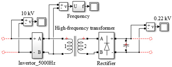
Figure 2.
Structure of the MATLAB model of a power router for DC grids.
The model flow chart of the inverter control system on the HV side of the power router is shown in Figure 3. The control system consisted of a voltage regulator (the Voltage regulator block in Figure 3) with a proportional-integral (PI) regulation algorithm, whose input was the effective voltage value on the HV side of the high-frequency transformer and the per-unit voltage setpoint. To form a sinusoidal voltage with a given frequency of 5000 Hz, the Sine Wave block was used, the output signal of which was multiplied by the output signal of the PI controller and was sent as a control signal to the input of the pulse-width modulated generator (the PWM Generator block in Figure 3) to form the corresponding inverter control pulses. Thus, the voltage level was regulated. An LC filter was used to smooth out the ripples and suppress noise at the inverter output. Voltage regulation on the HV and LV sides of a high-frequency transformer can also be performed by means of the input to the PI regulator operating on the LV side.
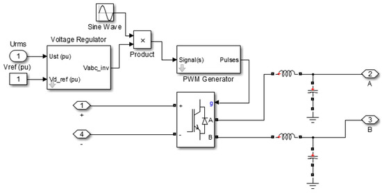
Figure 3.
Schematic of the inverter control system.
The schematic of the investigated power router-based DC distribution grid with distributed generation and energy storage units is shown in Figure 4. The power router with single-phase high-frequency transformers connects high and low-voltage DC grids. The availability of energy storage on the LV side of the power router allows effective management of the grid load profile and smoothing out of possible voltage and power fluctuations that are due to the presence of RES-based distributed generation units and other reasons. On the LV side of the power router, it is possible to connect an inverter to a voltage controller for AC consumers. The high-capacity battery storage connected to the HV side of the power router makes it possible to increase the reliability of the power supply and smooth out voltage and power fluctuations in case the microgrid in question switches to the island mode.
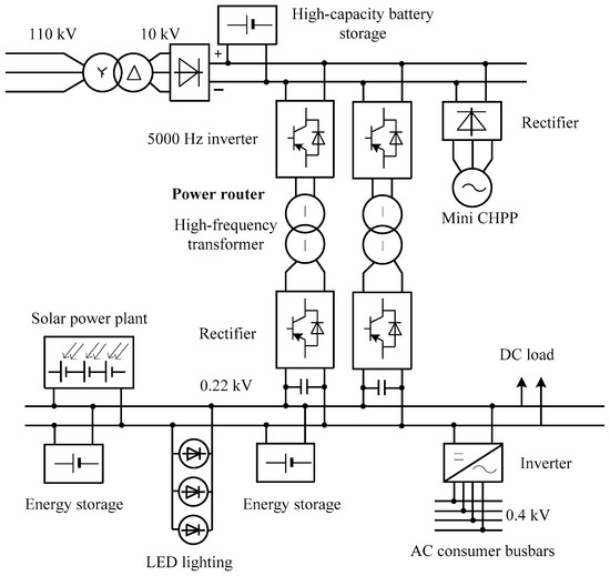
Figure 4.
Diagram of the investigated power router-based DC grid.
To study the normal and emergency operating conditions of the described power grid, we have developed a corresponding computer model. The flow chart of the MATLAB model of the power router-based DC and AC distribution system is shown in Figure 5. The power grid on the 10 kV side of the power router is connected through a transformer to the 110 kV power supply system (PSS).
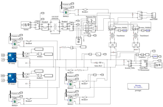
Figure 5.
Flow chart of the MATLAB model of the investigated power router-based grid.
Energy storage units based on lithium-ion batteries [39] were modeled by standard Battery blocks of the MATLAB SimPowerSystems package. The HV side of the power router used a 10,000 Ah battery, and the LV side used 4000 Ah energy storage units.
The following distributed generation units were simulated in the grid:
- mini CHPP with a capacity of 2.5 MW-A on the 10 kV side of the power router;
- solar power plant (SPP) on the 0.22 kV side.
The flow chart of the mini CHPP model is shown in Figure 6. The mini CHPP turbine generator was modeled with Synchronous Machine pu Fundamental, a standard block of the SymPowerSystems library of the MATLAB environment. The structural diagram of the adopted steam turbine model with intermediate steam extraction (Steam turbine block in Figure 6) is shown in Figure 7. For the thyristor exciter (Exciter block in Figure 6), we used a model of a first-order aperiodic link with the coefficient ke = 1, time constant Te = 0.025 s, and a voltage limiting block [40]. Regulation of rotor speed and turbine generator voltage was performed using models of automatic regulator of speed (ARS) (the Automatic regulator of rotor speed block in Figure 6) and automatic regulator of excitation (the MARE block in Figure 6), which are proportional-integral-differential (PID) regulators described by the following transfer functions:
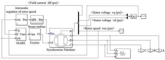
Figure 6.
Flow chart of the MATLAB model of the mini CHPP.
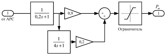
Figure 7.
Structural diagram of the steam turbine model with intermediate steam extraction.
- (1)
- ARS block:
- (2)
- MARE block:
The model also used predictive control algorithms, which were described in [41].
The model of the solar power plant was implemented using the MATLAB PV Array block, based on 400 parallel and 14 series-connected solar photovoltaic modules connected together, resulting in a maximum power of 415 kW. The grid used two models of solar power plants with current-voltage and power-voltage characteristics shown in Figure 8.
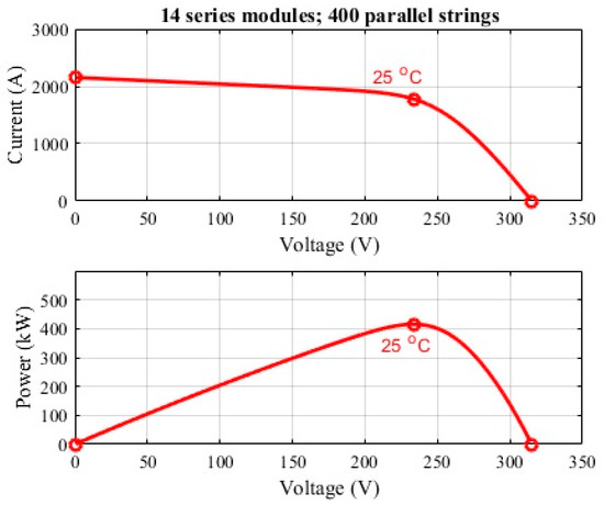
Figure 8.
Current-voltage and power-voltage characteristics of the solar power plant model.
The results of computer simulation attested to the efficacy and validity of the proposed DC distribution system model with power routers. The model is flexible and allows for additional connection of all possible distributed generation units and power consumers.
3. Results
To study the normal and emergency operating conditions of the presented DC and AC power grid with power routers, we considered a sudden disconnection of the grid from the 110 kV power supply system, the connection of an additional heavy load in the DC grid on the LV side of the power router, as well as a significant decrease in solar irradiance. For this purpose, to control the voltage under the above conditions, we used power routers with regulated inverters on the HV side as well as energy storage units that were either switched on permanently or switched on when the voltage dropped.
Disconnecting the DC distribution grid from the 110 kV power supply system caused a voltage sag. In this case, the use of power routers with a regulated inverter on the HV side made it possible to reduce the voltage sag in DC and AC grids slightly, but a greater effect of maintaining the nominal voltage was achieved on the 10 kV side of the power router because there was virtually no voltage sag. Where power routers with non-regulated inverters were used on the HV side, the depth of the voltage sag in the 10 kV grid reached 22%. The corresponding time dependencies of voltages in the DC and AC grid on the HV and LV sides of power routers are shown in Figure 9. It should be noted that in this experiment, all of the energy storage units in the grid were switched off.
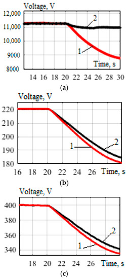
Figure 9.
Time dependencies of voltages: (a) on the HV side of PR; (b) on the LV side of PR (DC grid); (c) on the LV side of PR after inverter (in AC grid); 1—non-regulated PRs; 2—regulated PRs.
When energy storage units and especially the high-capacity battery storage on the HV side of the power router, were permanently connected to the grid, we observed that voltage stability was maintained in the grid, even after disconnection of the link with the 110 kV power supply system. In this case, maintaining the nominal voltage was achieved with regulated and non-regulated inverters on the HV side of power routers. To illustrate the above, Figure 10 shows the graph of voltage on the LV side of a power router in a DC grid when the 110 kV power supply system was switched off at 10 s into the simulation.
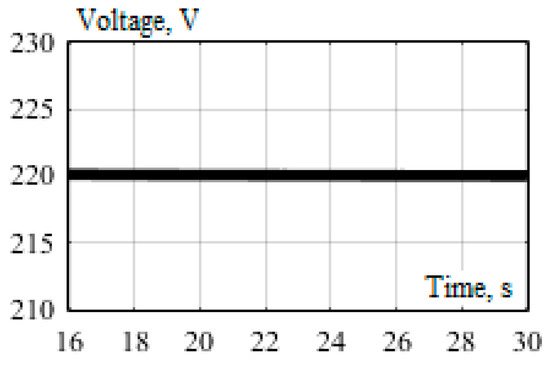
Figure 10.
Graph of voltage on the LV side of PR (DC grid).
The setup of another experiment to determine the possibility of voltage control in the grid in question was as follows: energy storage units at the solar power plants were switched on permanently, the high-capacity battery storage on the HV side of the power router was switched off, and switching-on of two energy storage units in the 220 V DC grid was used to boost the voltage level. The time dependencies for voltages in the grid when the 110 kV power supply system was switched off are shown in Figure 11. The results of the experiment demonstrated that the depth of the voltage sag in the grid was reduced when energy storage units at the solar power plants were permanently switched on: on the HV side of the power router—by 4% (curve one in Figure 9a and Figure 11a); on the LV side of the power router in the DC grid—by 11% (curve one in Figure 9b and Figure 11b); on the LV side of the power router downstream the inverter in the 0.4 kV AC grid—by 10% (curve one in Figure 9c and Figure 11c). The use of regulated power routers enabled reducing the depth of the voltage sag and virtually ruled out the voltage sag on the HV side. Furthermore, in the case of connecting additional energy storage units in the 220 V DC grid, it was possible to maintain the nominal voltage on the LV side of power routers even after switching off the 110 kV power supply system.
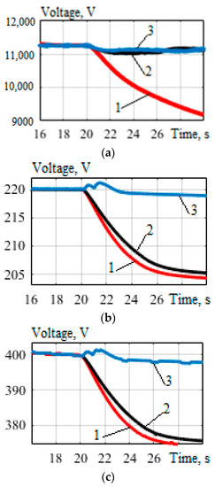
Figure 11.
Time dependencies of voltages when the power supply system was switched off: (a) on the HV side of PR; (b) on the LV side of PR (DC grid); (c) on the LV side of PR downstream the inverter (in the AC grid);1—non-regulated PRs; 2—regulated PRs; 3—regulated PRs with additional ES units connected in the 220 V grid.
Table 1 summarizes the results of the simulation of the voltage sag in the power grid in question when the 110 kV power supply system was switched off. The maximum depth of the voltage sag was determined as per the expression, %:
where —nominal voltage, V; —minimum voltage during a sag, V.

Table 1.
Results of simulation of the voltage sag when the power supply system was switched off.
Table 1 shows that the use of regulated power routers could reduce the voltage sag depth on the LV side of DC and AC grids by an average of 2% and on the HV side—by 19.5%. With energy storage units permanently switched on at solar power plants and the use of regulated power routers, it proved possible to reduce the maximum voltage sag depth by an average of 8.5% on the LV side in DC and AC grids and by 1%—on the HV side.
Connecting an additional heavy load to the DC grid on the LV side of the power router also caused a voltage sag. When energy storage units throughout the grid were switched off, the use of power routers with regulated inverters could reduce voltage sag depth to some extent. The obtained time dependencies for voltages under these operating conditions with energy storage units switched off are shown in Figure 12.
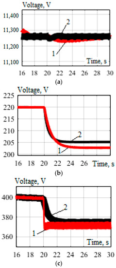
Figure 12.
Time dependencies for voltages after connection of a heavy load in the 220V grid: (a) on the HV side of the PR; (b) on the LV side of the PR (DC grid); (c) on the LV side of the PR downstream the inverter (in the AC grid); 1—non-regulated PRs; 2—regulated PRs.
Next, we also performed an experiment on connecting an additional heavy load to the 220 V DC grid in the case when the high-capacity battery storage was switched off on the HV side of the power router and energy storage units at the solar power plants were permanently switched on. To boost voltage, we also used the connection of two energy storage units to the 220 V DC grid. The time dependencies for grid voltages when a heavy load was connected at 20 s into the simulation are shown in Figure 13. The results of the experiment showed that the voltage sag depth in the grid was reduced when the energy storage at solar power plants was permanently switched on: on the LV side of the power router in the DC grid—by 4% (curve one in Figure 12b and Figure 13b); on the LV side of the power router downstream the inverter in the 0.4 kV AC grid—by 4.5% (curve one in Figure 12c and Figure 13c). The use of regulated power routers was able to reduce the voltage sag depth to some extent, and with additional connection in a series of energy storage units in the 220 V DC grid, it was possible to raise the voltage to its nominal value on the LV side of power routers (curve three in Figure 13).
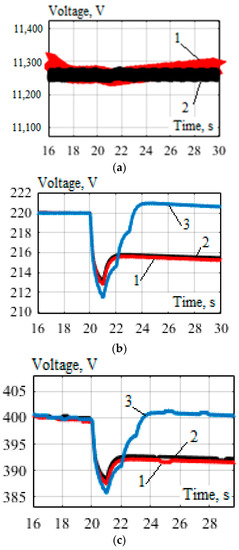
Figure 13.
Time dependencies for voltages: (a) on the HV side of the PR; (b) on the LV side of the PR (DC grid); (c) on the LV side of the PR downstream of the inverter (in the AC grid); 1—non-regulated PRs; 2—regulated PRs; 3—regulated PRs when connected in series in the 220 V grid.
Table 2 summarizes the results of the simulation of the voltage sag in the given power grid when an additional heavy load was connected. Table 2 shows that the use of regulated power routers was able to reduce the voltage sag depth on the LV side of the DC and AC grid by 1% on average, and with permanently connected energy storage units at the solar power plants, it made it possible to reduce this value by an average of 3%.

Table 2.
Voltage sag simulation results with a heavy load connected.
The voltage sag in the grid was also simulated when solar irradiance decreased significantly, which reduced the generation of electricity at SPPs. Regulated power routers and energy storage units at the solar power plant were used to boost voltage. We observed a slight voltage sag when the SPP power lowered, and the use of regulated power routers made it possible to reduce the voltage sag depth to some extent. The corresponding time dependencies for voltages are shown in Figure 14.
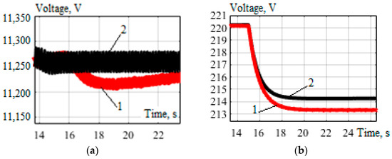
Figure 14.
Time dependencies for voltages in the case of a decrease in solar irradiance: (a) on the HV side of PRs; (b) on the LV side of PRs (DC grid); 1—non-regulated PRs; 2—regulated PRs.
The results of voltage regulation with the help of energy storage units in the case of a decrease in solar irradiance are shown in Figure 15.
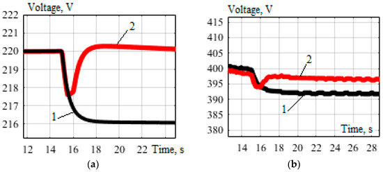
Figure 15.
Time dependencies for voltages: (a) on the LV side of PRs (DC grid); (b) on the LV side of PRs (in the AC grid); 1—ES units at SPPs were permanently switched on; 2—ES units at SPPs were switched on when the voltage dropped.
The voltage sag depth in the DC grid was 1.6 times less when energy storage units were permanently switched on at SPPs, as compared to the case when energy storage units were not used (curve one in Figure 14b and Figure 15a). However, it proved impossible to raise the voltage to its nominal value with permanently switched-on ES units. Increasing the voltage to its nominal value in the DC and AC grid, given the reduced power of SPPs, could be achieved by connecting ES units when the voltage drops (curve two in Figure 15).
4. Conclusions
The study outlined a computer model for power router-based integration of DC and AC microgrids with distributed generation and energy storage units. The model is flexible and allows for additional connection of any distributed generation units and power consumers. The results of the computer simulation allow us to draw the following conclusions:
- In the case of operation without energy storage units, the use of power routers with a regulated inverter on the HV side made it possible to reduce the voltage sag depth on the LV side in DC and AC grids by 2% on average when the power supply system was switched off. However, a greater effect of maintaining the voltage at the level of its nominal value was achieved on the 10 kV side of the power router: the voltage sag depth reduction was 19.5%. If power routers with non-regulated inverters on the HV side were used, the voltage sag depth in the 10 kV grid reached 22%.
- When energy storage units, especially the high-capacity battery storage on the HV side of the power router, were permanently connected to the grid, we observed that voltage stability was ensured in the grid, even after disconnection from the 110 kV power supply system. In this case, maintaining the nominal voltage was achieved with both regulated and non-regulated inverters on the HV side of power routers.
- When energy storage units at solar power plants were permanently switched on during the period of disconnection from the power supply system, the voltage sag depth in the grid was reduced: on the HV side of the power router—by 4%; on the LV side of the power router in the DC grid—by 11%; on the LV side of the power router downstream the inverter in the 0.4 kV AC grid—by 10%. The use of regulated power routers also enabled reducing the voltage sag depth and virtually ruled out the voltage sag on the HV side. Furthermore, in the case of connecting additional energy storage units in the 220 V DC grid, it was possible to maintain the nominal voltage on the LV side of power routers even after switching off the 110 kV power supply system.
- With disconnected energy storage units throughout the grid, in the case of the connection of a heavy load, the use of power routers with regulated inverters allowed reducing the voltage sag depth on the LV side of the DC and AC grid by 1% on average, and with permanently connected energy storage units at the solar power plants, it allowed reducing its value by an average of 3%.
- When energy storage units at solar power plants were permanently switched on during the connection of a heavy load, the voltage sag depth in the grid was reduced: on the LV side of the power router in the DC grid—by 4%; on the LV side of the power router downstream the inverter in the 0.4 kV AC grid—by 4.5%. The use of regulated power routers and additionally connected energy storage units in the 220 V DC grid made it possible to raise the voltage to its nominal value on the LV side of power routers.
- In the case when solar irradiance decreased significantly, thus reducing the output of electricity generation at the solar power plant, a small voltage sag in the grid occurred. The use of regulated power routers made it possible to reduce the voltage sag depth to some extent. It was possible to increase the voltage to its nominal value in the DC and AC grid by connecting a series of energy storage units at the solar power plant.
Thus, the developed computer model of a hybrid DC and AC grid based on power routers makes it possible to study the operating conditions of such grids and voltage control methods. The proposed methods of voltage control using power routers and energy storage devices in normal and emergency operating conditions of DC and AC grids have shown their performance and can be recommended for practical application. Further development of the proposed methods of voltage control in hybrid DC and AC grids will focus on the coordinated control of power routers and energy storage devices in terms of their residual charges.
Author Contributions
Conceptualization, Y.B., and A.K. methodology, Y.B., A.K., and K.S.; software, Y.B.; validation, Y.B., A.K., and K.S.; formal analysis, A.K., and K.S.; investigation, Y.B., A.K., and K.S.; resources, K.S.; data curation, Y.B.; writing—original draft preparation, Y.B., A.K., and K.S.; writing—review and editing, Y.B. and K.S.; visualization, K.S.; supervision, K.S.; project administration, A.K., and K.S.; funding acquisition, K.S. All authors have read and agreed to the published version of the manuscript.
Funding
This research received no external funding.
Data Availability Statement
Data sharing is not applicable. No new data were created or analyzed in this study. Data sharing is not applicable to this article.
Conflicts of Interest
The authors declare no conflict of interest.
References
- Hasan, M.K.; Habib, A.A.; Shukur, Z.; Ibrahim, F.; Islam, S.; Razzaque, M.A. Review on cyber-physical and cyber-security system in smart grid: Standards, protocols, constraints, and recommendations. J. Netw. Comput. Appl. 2023, 209, 103540. [Google Scholar] [CrossRef]
- Bayindir, R.; Colak, I.; Fulli, G.; Demirtas, K. Smart grid technologies and applications. Renew. Sustain. Energy Rev. 2016, 66, 499–516. [Google Scholar] [CrossRef]
- Panda, D.K.; Das, S. Smart grid architecture model for control, optimization and data analytics of future power networks with more renewable energy. J. Clean. Prod. 2021, 301, 126877. [Google Scholar] [CrossRef]
- Bhalshankar, S.S.; Thorat, C.S. Integration of smart grid with renewable energy for energy demand management: Puducherry case study. In Proceedings of the 2016 International Conference on Signal Processing, Communication, Power and Embedded System (SCOPES), Odisha, India, 3–5 October 2016; pp. 1–5. [Google Scholar] [CrossRef]
- Bulatov, Y.; Kryukov, A.; Nguyen, V.H.; Tran, D.H. Fuzzy Controller of Rotation Angle of Blades of Horizontal-Axial Wind Power Generation Plant. In Advances in Intelligent Systems and Computing; Springer: Berlin/Heidelberg, Germany, 2019; Volume 983, pp. 105–115. [Google Scholar] [CrossRef]
- Suslov, K.; Solonina, N.; Stepanov, V. A principle of power quality control in the intelligent distribution networks. In Proceedings of the 2015 International Symposium on Smart Electric Distribution Systems and Technologies (EDST), Vienna, Austria, 8–11 September 2015; pp. 260–264. [Google Scholar] [CrossRef]
- Antoniadou-Plytaria, K.E.; Kouveliotis-Lysikatos, I.N.; Georgilakis, P.S.; Hatziargyriou, N.D. Distributed and Decentralized Voltage Control of Smart Distribution Networks: Models, Methods, and Future Research. IEEE Trans. Smart Grid 2017, 8, 2999–3008. [Google Scholar] [CrossRef]
- Colak, I.; Bayindir, R.; Sagiroglu, S. The Effects of the Smart Grid System on the National Grids. In Proceedings of the 2020 8th International Conference on Smart Grid (icSmartGrid), Paris, France, 17–19 June 2020; pp. 122–126. [Google Scholar] [CrossRef]
- Ahmethodzic, L.; Music, M. Comprehensive review of trends in microgrid control. Renew. Energy Focus 2021, 38, 84–96. [Google Scholar] [CrossRef]
- Mortezapour, V.; Lesani, H. Hybrid AC/DC microgrids: A generalized approach for autonomous droop-based primary control in islanded operations. Int. J. Electr. Power Energy Syst. 2017, 93, 109–118. [Google Scholar] [CrossRef]
- Sikorski, T.; Rezmer, J. Distributed Generation and Its Impact on Power Quality in Low-Voltage Distribution Networks. In Power Quality Issues in Distributed Generation; Luszcz, J., Ed.; IntechOpen: London, UK, 2015. [Google Scholar] [CrossRef]
- Aderibigbe, M.A.; Adoghe, A.U.; Agbetuyi, F.; Airoboman, A.E. Impact of Distributed Generations on Power Systems Stability: A Review. In Proceedings of the 2022 IEEE Nigeria 4th International Conference on Disruptive Technologies for Sustainable Development (NIGERCON), Lagos, Nigeria, 5–7 April 2022. [Google Scholar] [CrossRef]
- Voropai, N.I.; Suslov, K.V.; Sokolnikova, T.V.; Styczynski, Z.A.; Lombardi, P. Development of power supply to isolated territories in Russia on the bases of microgrid concept. In Proceedings of the 2012 IEEE Power and Energy Society General Meeting, San Diego, CA, USA, 22–26 July 2012. [Google Scholar] [CrossRef]
- Li, L.; Wang, X. Design and operation of hybrid renewable energy systems: Current status and future perspectives. Curr. Opin. Chem. Eng. 2021, 31, 100669. [Google Scholar] [CrossRef]
- Chen, D.; Xu, Y.; Huang, A.Q. Integration of DC Microgrids as Virtual Synchronous Machines Into the AC Grid. IEEE Trans. Ind. Electron. 2017, 64, 7455–7466. [Google Scholar] [CrossRef]
- Sechilariu, M.; Locment, F.; Wang, B. Photovoltaic electricity for sustainable building. Efficiency and energy cost reduction for isolated DC microgrid. Energies 2015, 8, 7945–7967. [Google Scholar] [CrossRef]
- dos Santos, L.T.; Sechilariu, M.; Locment, F. Optimized load shedding approach for grid-connected DC microgrid systems under realistic constraints. Buildings 2016, 6, 50. [Google Scholar] [CrossRef]
- Sechilariu, M.; Locment, F. Urban DC Microgrid: Intelligent Control and Power Flow Optimization; Butterworth-Heinemann: Oxford, UK, 2016; p. 306. [Google Scholar]
- Bulatov, Y.N.; Kryukov, A.V. Distribution DC Electrical Network with Power Router. In Proceedings of the 2019 International Multi-Conference on Industrial Engineering and Modern Technologies (FarEastCon), Vladivostok, Russia, 1–4 October 2019. [Google Scholar] [CrossRef]
- Mahmud, M.A.; Roy, T.K.; Saha, S.; Haque, M.E.; Pota, H.R. Robust nonlinear adaptive feedback linearizing decentralized controller design for islanded DC microgrids. IEEE Trans. Ind. Appl. 2019, 55, 5343–5352. [Google Scholar] [CrossRef]
- Azizi, A.; Peyghami, S.; Mokhtari, H.; Blaabjerg, F. Autonomous and decentralized load sharing and energy management approach for DC microgrids. Electr. Power Syst. Res. 2019, 177, 106009. [Google Scholar] [CrossRef]
- Ghosh, S.K.; Roy, T.K.; Pramanik, M.A.H.; Sarkar, A.K.; Mahmud, M.A. An Energy Management System-Based Control Strategy for DC Microgrids with Dual Energy Storage Systems. Energies 2020, 13, 2992. [Google Scholar] [CrossRef]
- Van Nguyen, T.; Kim, K.-H. Power Flow Control Strategy and Reliable DC-Link Voltage Restoration for DC Microgrid under Grid Fault Conditions. Sustainability 2019, 11, 3781. [Google Scholar] [CrossRef]
- Nguyen, T.V.; Kim, K.-H. An Improved Power Management Strategy for MAS-Based Distributed Control of DC Microgrid under Communication Network Problems. Sustainability 2020, 12, 122. [Google Scholar] [CrossRef]
- Li, X.; Guo, L.; Li, Y.R.; Hong, C.; Zhang, Y.; Guo, Z.; Huang, D.; Wang, C. Flexible Interlinking and Coordinated Power Control of Multiple DC Microgrids Clusters. IEEE Trans. Sustain. Energy 2018, 9, 904–915. [Google Scholar] [CrossRef]
- Vuyyuru, U.; Maiti, S.; Chakraborty, C. Active Power Flow Control Between DC Microgrids. IEEE Trans. Smart Grid 2019, 10, 5712–5723. [Google Scholar] [CrossRef]
- Bracale, A.; Caramiaa, P.; Carpinelli, G.; Mottola, F.; Proto, D. A Hybrid AC/DC Smart Grid to Improve Power Quality and Reliability. In Proceedings of the 2012 IEEE International Energy Conference and Exhibition (ENERGYCON), Florence, Italy, 9–12 September 2012; pp. 507–514. [Google Scholar]
- Monteiro, V.; Monteiro, L.F.C.; Franco, F.L.; Mandrioli, R.; Ricco, M.; Grandi, G.; Afonso, J.L. The Role of Front-End AC/DC Converters in Hybrid AC/DC Smart Homes: Analysis and Experimental Validation. Electronics 2021, 10, 2601. [Google Scholar] [CrossRef]
- Alsokhiry, F.; Adam, G.P. Multi-Port DC-DC and DC-AC Converters for Large-Scale Integration of Renewable Power Generation. Sustainability 2020, 12, 8440. [Google Scholar] [CrossRef]
- Yaqub, R. Phasor Measurement Unit Assisted Inverter—A Novel Approach for DC Microgrids Performance Enhancement. Electricity 2021, 2, 330–341. [Google Scholar] [CrossRef]
- Paez, J.D.; Frey, D.; Maneiro, J.; Bacha, S.; Dworakowski, P. Overview of DC–DC Converters Dedicated to HVdc Grids. IEEE Trans. Power Deliv. 2019, 34, 119–128. [Google Scholar] [CrossRef]
- Khan, Z.W.; Minxiao, H.; Kai, C.; Yang, L.; Rehman, A.U. State of the Art DC-DC Converter Topologies for the Multi-Terminal DC Grid Applications: A Review. In Proceedings of the 2020 IEEE International Conference on Power Electronics, Smart Grid and Renewable Energy (PESGRE2020), Cochin, India, 2–4 January 2020. [Google Scholar]
- Mohammadi, F.; Nazri, G.-A.; Saif, M. A Bidirectional Power Charging Control Strategy for Plug-in Hybrid Electric Vehicles. Sustainability 2019, 11, 4317. [Google Scholar] [CrossRef]
- Monteiro, V.; Martins, J.S.; Aparício Fernandes, J.C.; Afonso, J.L. Review of a Disruptive Vision of Future Power Grids: A New Path Based on Hybrid AC/DC Grids and Solid-State Transformers. Sustainability 2021, 13, 9423. [Google Scholar] [CrossRef]
- Juneja, A.; Bhattacharya, S. Power router: Architectures and functionalities toward Energy Internet. In Proceedings of the 2011 IEEE International Conference on Smart Grid Communications (SmartGridComm), Brussels, Belgium, 17–20 October 2011; pp. 31–36. [Google Scholar]
- Bulatov, Y.N.; Kryukov, A.V.; Arsentiev, G.O. Use of Power Routers and Renewable Energy Resources in Smart Power Supply Systems. In Proceedings of the 2018 International Ural Conference on Green Energy (UralCon), Chelyabinsk, Russia, 4–6 October 2018; pp. 143–148. [Google Scholar] [CrossRef]
- She, X.; Huang, A.Q.; Burgos, R. Review of Solid State Transformer technologies and their applications in power distribution system. IEEE J. Emerg. Sel. Top. Power Electron. 2013, 1, 186–198. [Google Scholar] [CrossRef]
- Bansode, S.G.; Joshi, P.M. Solid state transformers: New approach and new opportunity. In Proceedings of the 11th IRF International Conference, Pune, India, 15 June 2014; pp. 15–21. [Google Scholar]
- Nishi, Y. Lithium ion secondary batteries; past 10 years and the future. J. Power Sources 2001, 100, 101–106. [Google Scholar] [CrossRef]
- Anderson, P.M.; Fouad, A.A. Power System Control and Stability, 2nd ed.; IEEE Press: New York, NY, USA, 2003. [Google Scholar]
- Bulatov, Y.; Kryukov, A.; Suslov, K. Using Group Predictive Voltage and Frequency Regulators of Distributed Generation Plants in Cyber-Physical Power Supply Systems. Energies 2022, 15, 1253. [Google Scholar] [CrossRef]
Disclaimer/Publisher’s Note: The statements, opinions and data contained in all publications are solely those of the individual author(s) and contributor(s) and not of MDPI and/or the editor(s). MDPI and/or the editor(s) disclaim responsibility for any injury to people or property resulting from any ideas, methods, instructions or products referred to in the content. |
© 2022 by the authors. Licensee MDPI, Basel, Switzerland. This article is an open access article distributed under the terms and conditions of the Creative Commons Attribution (CC BY) license (https://creativecommons.org/licenses/by/4.0/).