Abstract
Offshore wind energy is a sustainable renewable energy source that is acquired by harnessing the force of the wind offshore, where the absence of obstructions allows the wind to travel at higher and more steady speeds. Offshore wind has recently grown in popularity because wind energy is more powerful offshore than on land. Prior to the development of floating structures, wind turbines could not be deployed in particularly deep or complicated seabed locations since they were dependent on fixed structures. With the advent of floating structures, which are moored to the seabed using flexible anchors, chains, or steel cables, wind turbines can now be placed far offshore. The deployment of floating wind turbines in deep waters is encouraged by several benefits, including steadier winds, less visual impact, and flexible acoustic noise requirements. A thorough understanding of the physics underlying the dynamic response of the floating offshore wind turbines, as well as various design principles and analysis methods, is necessary to fully compete with traditional energy sources such as fossil fuels. The present work offers a comprehensive review of the most recent state-of-the-art developments in the offshore wind turbine technology, including aerodynamics, hydromechanics, mooring, ice, and inertial loads. The existing design concepts and numerical models used to simulate the complex wind turbine dynamics are also presented, and their capabilities and limitations are discussed in detail.
1. Introduction
Global warming and climate pattern changes are some major consequences of the human activities that are caused by the overuse of fossil fuels [1]. Renewable energy, on the other hand, has the capability of decreasing greenhouse gas emissions by providing a sustainable and clean energy resource [2,3]. Based on the statistical data from the International Energy Agency (IEA), the renewable energy market share is growing steadily, in which wind power takes up of the total growth [4]. Offshore wind is advantageous among the various forms of renewable energy since it can produce large amounts of electricity [5]. Over 6000 MW of new offshore wind energy installations were made worldwide in 2021, following the construction of 5618 MW in 2020 (Figure 1). By the end of 2021, the capacity increased to 39,006 MW, thanks to the more than 200 active projects. Annual new installations are expected to surpass the milestones of 20 GW by 2025 and 40 GW in 2030, with a compound average annual growth rate (ACAGR) of over up to 2025 and until the end of the decade [6].
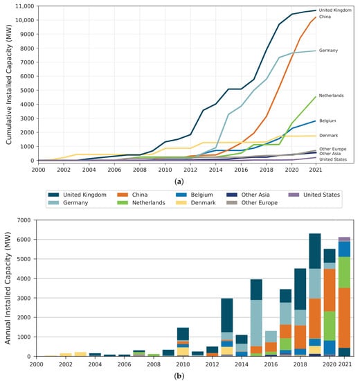
Figure 1.
Global cumulative offshore wind energy deployment and annual capacity trends through 2021 [8]. (a) Cumulative installed wind energy trends for countries with the highest record in the past two decades. (b) Annual new installation trends for countries with the highest record in the past two decades.
The world’s first offshore wind turbine was installed in 1990 in Nogersund, Sweden. The Netherlands, Sweden, Denmark, and the UK have established a number of offshore wind power demonstration projects over the past two decades, which were funded mainly by the governments and research organizations [7].
The vast majority of operational offshore wind turbines are mounted on bottom-fixed substructures, such as monopile, jacket, tripod, and gravity base substructures, which are positioned in shallow to intermediate sea depths of up to 50 m. Although wind resources are significant in locations with sea depths over 50 m, fixed-bottom offshore wind turbines do not have an economic justification for their use in energy extraction at these depths [9]. With the advent of floating structures, however, wind turbines can now be placed far offshore. The deployment of floating wind turbines in deep waters has several advantages, such as steadier winds, less visual impact, and flexible acoustic noise requirements. In recent years, various types of floating offshore wind turbines (FOWTs) with different support platforms, anchoring and mooring configurations have been proposed and investigated. The designs have benefited from the floating support structure concepts employed by the oil and gas offshore industry, such as semisubmersibles, tension leg platforms (TLPs), and spar-buoys.
In 2008, Blue H Technologies deployed a tension leg platform (TLP) with an 80 kW rated capacity 21.3 km off the coast of Apulia, Italy, as the first floating wind turbine trial [10]. In 2009, the Norwegian State Oil Company, Statoil, installed HyWind, a 2.3 MW wind turbine equipped with a spar-type support platform, which was the world’s first floating offshore wind turbine on the MW scale [11]. In 2011, the 2 MW turbine-equipped WindFloat, designed by Principle Power Inc., was deployed 4 km off the coast of Aguçadoura, Portugal, at a 45 m depth [10].
Onshore wind turbines have recently improved their economic viability relative to the conventional energy sources [12,13]. This achievement was made possible by a number of developments, including improved control systems [14,15,16], larger wind turbines [17,18], higher fidelity models [19,20], the collective installation of wind turbines called wind farms [21,22,23], improved energy loss recovery [24,25,26], and more optimized designs [27,28]. The construction of offshore wind turbines, however, is more expensive and capital-intensive than that of onshore wind turbines. Additionally, costs may change based on factors such as the distance from the coast, the sea conditions, and more [29]. In general, the tower and foundation of an offshore wind turbine are approximately and three times more costly than their onshore counterparts, respectively [30]. For offshore wind platforms with fixed bottoms, the most expensive component is the turbine itself, contributing about to the overall expense, while the assembly and installation is , followed by the construction of foundation and substructure at [31]. On the other hand, for the FOWTs, the wind turbine and installation and assembly take up about and of the total cost, respectively, with the foundation and substructure being the most expensive components at [31]. Of course, the ratios mentioned above may change with the industrial development of the offshore wind turbines in the future.
Compared to fixed-bottom offshore and onshore wind turbines, the overall cost of FOWTs is significantly greater due to the high cost of floating offshore support structures. However, the most densely populated areas across the world are along the coasts where FOWTs are a better alternative than onshore wind turbines [32,33]. Therefore, many of the concerns that are related to onshore wind turbines such as visual and noise distractions can be avoided by placing the wind turbines far offshore [34,35].
Stronger and more consistent winds also promote offshore wind energy, which results in higher energy yield and lighter loads on the rotor and nacelle assemblies. [36]. In shallow to intermediate water depths, where wind resources are substantial, the installation of fixed-bottom offshore wind turbines is more practical and cost-effective than floating platforms. However, the countries that border the Atlantic Ocean, including the United States, Japan, and west European nations, have limited coastal territorial waters that are less than 50 m deep. As a result, there has been a considerable interest in floating offshore wind turbines (FOWTs) over the past ten years [9].
The current study provides a thorough overview of advances in FOWT technology from the perspective of design concepts, loading, and analysis tools and presents the future prospects for the floating offshore wind industry.
2. Design Concepts for Floating Offshore Wind Turbines
FOWTs are among the concepts that can efficiently and economically capture energy from deep-water offshore wind resources [37,38]. A wind turbine mounted on a floating foundation is part of the FOWT idea, which enables the production of power in deep waters where bottom-fixed wind turbines are not economically feasible. Different floating wind turbine concepts are shown in Figure 2.
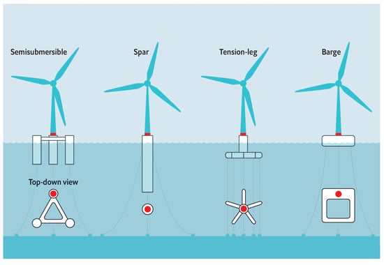
Figure 2.
Different FOWT design concepts [40].
Several FOWT designs have been developed on barge, spar, TLP, and semisubmersible foundations [39]. Every FOWT design has advantages and disadvantages that should be taken into account depending on the installation site parameters, such as proximity to the shore, water depth, environmental factors, and sea bottom characteristics. A floating offshore wind turbine system consists of the following:
- Platform and tower;
- Blades, nacelle and hub;
- Mooring system with tendons, clump masses, and mooring lines;
- Fairleads and anchors;
- Gear box, high-speed and low-speed shafts with a mechanical brake system;
- Controller and electricity generator;
- Hydraulics and cooling systems;
- Pitch and yaw mechanisms.
The performance of FOWTs is affected by the displacement in six degrees of freedom (6DOF), which consists of three translational (surge X, sway Y, and heave Z) and three rotational (roll, pitch, and yaw) modes of movement, as can be seen in Figure 3. The motions in 6DOF are caused by the combined influence of the environmental and system restoring loads that act on a floating wind turbine [41].
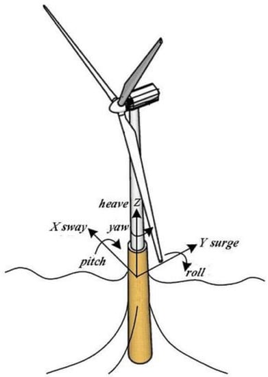
Figure 3.
The degrees of freedom of an offshore floating wind turbine platform [42].
The following section reviews some well-known and cutting-edge ideas for floating offshore wind turbine platforms and mooring methods for upcoming offshore wind farms in relatively deep waters.
2.1. Spar-Type Platform
Floating spar-buoy offshore wind turbines (FSOWTs) are one of the best design concepts that have the potential to effectively harvest energy in deep waters [5,43]. It might be claimed that FSOWTs are unlikely to be the best solution for FOWTs due to the complexity of their installation at deep drafts; nevertheless, they are the only viable option for mass production owing to their ease of construction [44]. In combination with the mass-dominated dynamic behavior, the deep draft of the spar and the comparatively small water plane area reduce the heave excitation forces, which results in great hydrodynamic stability and a very strong performance in the heave mode of motion.
A typical configuration of a spar-buoy consists of a cylindrical floating spar-buoy that is fastened to the ground by cables. The spar-type platform with either a catenary or taut mooring system maintains its stability by lowering the center of mass with regard to the center of buoyancy using the substantial ballast at the lower level of the structure, significantly contributing to the roll, pitch and displacement. Mooring lines are utilized to prevent drifting and limit the surge and sway motions. For spar-type platforms, it is also possible to eliminate the wind-induced yaw motion by using delta mooring lines [45].
2.2. Semi-Submersible Platform
The semi-submersible concept was originally developed for use in the offshore oil and gas industry where a large drill deck was needed [46]. Semi-submersible FOWTs typically consist of a number of vertical columns joined by cross braces or pontoons [47,48,49]. Heave plates or skirts are usually attached to the bottom of the columns in order to increase the added mass and damping. However, an additional lift force on heave plates or skirts may appear due to vortex shedding [50].
Thanks to the small draft, the deployment of semisubmersible FOWTs can be made in the regions with a water depth of ranging from 40 m to 50 m. They can be assembled on dry docks, where the platforms are then towed offshore using standard tug boats providing significant logistical and financial savings. Limited sensitivity to water depth, quayside integration, large payload capacity and the possibility to reposition the platform following field abandonment are just a few advantages of semisubmersible platforms. Furthermore, especially for the systems where the turbine is located on the side of the floater, the operation and maintenance are relatively easier [51]. The ballasts inside the chamber provide a better stability in harsh environments, even though obtaining an active ballast in the system may produce additional needs for maintenance.
2.3. Barge Platform
Barges achieve stability using their distributed buoyancy, taking advantage of the large water plane area. One of the most common types of barge platforms used in offshore wind industry is Ideol. This type of floating structure is usually distinguished by a rectangular annulated-shaped floating substructure with a pool at its center (a.k.a., the moon pool), which diminishes the floater motion by absorbing the wave loads [52].
For barge platforms, a catenary mooring system is typically utilized to prevent drifting [53]. It is also possible to use abandoned vessels as a floating platform for wind turbines; however, the applicability of both barges and ship-shaped structures is constrained by several problems that include, depending on the system size, high tower-base bending moments, pitch dynamic motions induced by the waves, and associated accelerations at the nacelle and wave loading [54]. However, it may be feasible to employ such a notion in calm bays and seas.
2.4. Tension Leg Platform
The stability of the tension leg platform (TLP) is utilized by its excess buoyancy as well as the vertical tendons that are anchored to the seabed. The key benefit of employing TLPs over spar and semisubmersible platform technologies is the smaller and lighter substructure [55]. TLPs have a considerably smaller footprint due to the taut mooring lines and the resulting vertical tension at the anchorage.
To support large vertical loads, different types of anchoring systems, such as suction anchors, gravity anchors, or anchor piles, are used depending on the geology and seabed conditions [56]. The biggest problem with TLPs is that they rely on pretensioned tendons to maintain stability. In this regard, a possible failure in the mooring or anchoring system may result in capsizing since the mooring system restores the stability of the platform [57].
2.5. Catamaran Platform
The largest construction vessel in the world, a.k.a. Pioneering Spirit, and several environmentally friendly power boats were built using catamarans, which are frequently utilized in the maritime transportation and leisure industries [58]. Catamarans are well known for their high levels of stability and vast usable deck space, both of which are advantageous for offshore renewable energy systems. For heeling stability, a catamaran primarily relies on its beam (width) and demi-hull buoyancy. This implies that the stability increases with increasing beam width and length. An essential design factor for a FOWT is its longitudinal stability (pitch), which has a direct impact on the amount of power generated [59]. As a result of their renowned transverse stability, there is a significant chance that converting a catamaran into a FOWT support platform is worthwhile. A standard catamaran can be transformed into a platform for tidal energy according to various studies [60,61,62]. There is not much literature that emphasizes converting a catamaran into a useful support platform for operating wind turbines. This is a new technology for FOWTs, tested only at small scales and subject to continuous research. In this regard, single-point mooring catamarans were designed and tested for some special offshore operations [63]. The results showed that the side-to-side movement could only be avoided with external control methods. In a more recent work, an equally spaced semi-hull catamaran platform was proposed, where a wind turbine is placed in the middle of the platform with a mooring system of eight slack [64] (Figure 4). According to the numerical analyses, the proposed design had considerably reduced responses ( and reduction in rotor thrust and fore-aft tower-base bending moment, respectively) and boosted stability (up to pitch response reduction in comparison with the barge platform) [64].
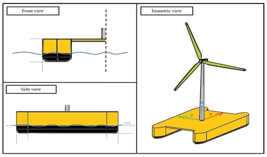
Figure 4.
Preliminary catamaran FOWT concept schematic [64].
2.6. Novel Platform Designs
In recent years, researchers have proposed novel floating platforms that take advantage of the strengths of existing concepts and combine them to achieve more cost-effective designs. Fully submersible platforms, for example, combine the advantages of semi-submersible and spar platforms (Figure 5a). This concept employs inclined side columns that are used to increase the water plane and thus the moment of inertia while minimizing the draft and stress on the support structure [65]. A fully submersible floating platform is similar to a semi-submersible one, but the middle parts of the columns are inclined outwards, while the upper and lower parts remain upright to connect to the center column via a set of cross braces and pontoons. This alteration lowers the platform’s center of gravity, which is the primary source of stability in spar platforms, while simultaneously increasing the moment of inertia from which semi-submersible platforms achieve stability [66]. The dynamic response analysis of fully submersible platforms indicates that this type of floating platform has a relatively better overall dynamic performance, and the cost is lower than that of a semi-submersible platform [65].
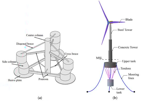
Figure 5.
Novel FOWT platform design concepts. (a) Fully-submerged platform initial design [65]. (b) TELWIND platform design concept [68].
TELWIND is a novel multi-body floating platform developed by ESTEYCO S.A.P. with a wide cylindrical platform and a cylindrical ballast body suspended by six tendons [67]. The spar of TELWIND is composed of a telescopic tower and two independent concrete bodies connected by suspension tendons (Figure 5b). The upper concrete body maintains buoyancy, while the lower concrete body serves as the ballasting body. The telescopic tower allows for wet towing of the pre-assembled system, as folding in the tower provides a more stable configuration for the structure. This floating platform is designed to withstand harsh metocean conditions. In this regard, TELWIND’s dynamic performance was tested both experimentally and numerically under various wind and wave load cases [68]. For this multi-body floating platform, the dynamic behavior is found to be highly sensitive to the state of tendons’ health.
3. Studies on Floating Offshore Wind Turbines
The dynamic behavior of FOWTs is crucial for the design, operation, maintenance, and administration of floating wind farms [69]. The dynamic responses of the wind turbine superstructure and associated control systems have become crucial as wind turbines have grown taller and more slender to produce more power. The systems that control the unwanted structural vibrations can increase the lifespan of wind turbines by decreasing stress and related fatigue and significantly reduce the maintenance requirement. Furthermore, the loads on the foundation, which often play a major role in the overall cost of offshore wind turbines, are considerably reduced. In order to develop a reliable control algorithm and evaluate structural integrity, it is important to determine the loads acting on the system (Figure 6 and Figure 7) as accurately as possible [70].
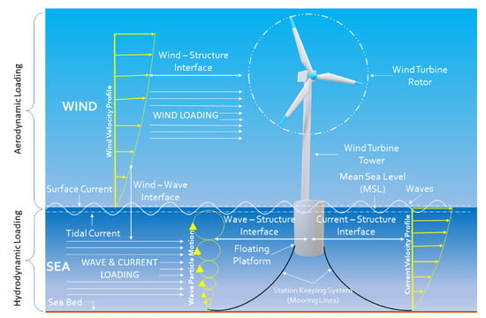
Figure 6.
Schematic diagram of fluid-structure interfaces and dynamic loads experienced by a FOWT [71].
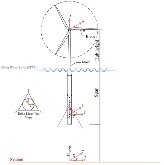
Figure 7.
Configuration of a spar-type FOWT and the used coordinate systems [72].
There is a two-way relationship between the aerodynamic and hydrodynamic performance of an offshore wind turbine with respect to environmental loads, structural health and integrity, control systems, material choice and design. This section only discusses the loads acting on a FOWT system without delving into the control systems or structural health of the FOWTs.
3.1. Aerodynamic Loads
A wind turbine is an energy converter that uses a mechanical-electrical process to convert wind kinetic energy to electricity. The wind induces lift and drag forces on the wind turbine blades, and the wind velocity at the rotor lowers owing to the presence of the rotor. The aerodynamic loads are inherently nonlinear and are produced by the skew inflow, dynamic and static wind flow, shear effects on the induction, dynamic stall, and large deflections of the blades. The periodic aerodynamic forces that occur due to the wind shear, off-axis winds, rotation of the rotor, turbulence induced fluctuations and dynamic effects are the main sources of fatigue loads and are crucial factors in the peak loads experienced by a wind turbine. Therefore, the determination of aerodynamic forces is extremely important for the dynamic response analysis, design, optimization and structural integrity assessment of such systems [73]. The state-of-the-art tools for calculating the aerodynamic loads are developed by solving the Navier–Stokes equations for compressible flows and by taking the flow near the blades into account.
The traditional blade element momentum (BEM) model developed by Glauert is a widely used technique for calculating the aerodynamic forces on a wind turbine [74]. The BEM model is capable of determining the steady forces and, thus, can estimate the power and thrust for various wind speeds, pitch angle settings, and rotational speeds [75]. The BEM theory was derived by combining the blade element theory and momentum theory, where the actual geometry of the rotor, such as the distribution of the chord and twist, the number of blades, and the airfoils, is disregarded. In other words, the BEM method couples the momentum theory with the local events taking place at the actual blades by applying blade element theory [73]. First, the momentum balance of an annular rotating stream tube going through the turbine is calculated. Next, the spanwise drag and lift forces on the blade cross-sections are computed. These two individual theories are employed iteratively until the aerodynamic loads converge to the desired results [73].
Some drawbacks of the BEM theory include not being able to predict the delayed stall caused by rotational effects and poor performance due to large velocities [76] or yawed flow. The advanced or extended blade element momentum theory can be implemented to account for the unsteady aerodynamic effects in the time-domain.
For a floating offshore wind turbine system, the time-dependent structural behavior of the system and the aerodynamic loads are strongly coupled. The loads on each blade element can be calculated using the induced wind velocity on each blade element at any given time and the velocity of the blade elements due to the blade motion [72]:
Here, is the air density, c is the chord length, is the lift coefficient, is the drag coefficient, () and () are the axial and tangential wind velocities, respectively, and are the blade element velocities in the perpendicular and tangential directions to the rotor plane, respectively, and is the length of blade element.
Figure 8 shows a spanwise transversal section of the blade element and the aerodynamic forces acting on it. In this figure, is the inflow angle, indicates the angle of attack, W is the vector summation of the tangential and axial wind velocities, and and represent the blade twist and pitch angles, respectively.
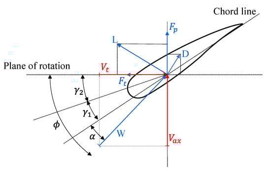
Figure 8.
Velocity and force components at the rotor plane [72].
The tangential and axial wind velocities are not equal to the rotational and free stream speed due to the presence of the rotor. Accordingly, tangential () and axial (a) induction factors are used to reflect the shift in the wind velocity as:
where is the velocity of the free stream, is the rotor’s rotational velocity, and r is the blade element radius.
The free stream velocity in the above formulation is computed at the wind turbine’s hub-height, and it can either be steady or turbulent [77,78]. The von Karman or Kaimal and Maan spectrums can be used to simulate a turbulent wind field [79]. There are other theoretical approaches for aerodynamic calculations on the horizontal axis wind turbine rotors.
The traditional BEM theory is not applicable for shrouded or ducted wind turbines because this theory is based on the assumption that the axial induction is half its value when the far wake coincides with the rotor plan [80]. However, the traditional BEM axial induction factor becomes invalid due to the presence of a diffuser or any other system which modifies the flow. Therefore, it was proposed to replace the traditional axial induction factor with a generalized rotor plane axial induction, [80]. This approach is called the generalized actuator disc theory (GADT), where the geometry of the specified diffuser is taken into account by the parameter. The GADT was later modified to include an effective diffuser efficiency, which depended on the thrust loading or axial induction [81]. This was achieved by applying Glauert corrections to the diffuser-augmented wind turbines in the turbulent wake state. An empirical model for the axial velocity profile at the rotor plane prediction was also established, which enabled the estimation of the diffuser’s axial induction.
Aerodynamic loads can also be calculated using the panel and vortex methods [82]. The first calculations based on vortex methods were performed, by hand, independently by Prager in 1928 [83] and Rosenhead in 1931 [84,85]. The vortex approach is predicated on the idea that the whole domain around the body surface and wake region experiences inviscid, incompressible, and irrotational flow. Solving Laplace’s equation with the proper velocity boundary conditions on the body surface and far field yields the velocity potential [86].
Vortex methods are powerful tools to study the interactions of blade wake vortices with each other as well as with other rotorcraft components. The majority of current comprehensive rotorcraft analysis codes use vortex methods, which allow the lifting surface (such as a rotor blade) to be modeled in a variety of ways. These modeling techniques include the lifting line theory (LLT), Weissinger’s LLT (extended lifting-line theory), the lifting surface method, and the source-doublet panel method [87]. The issue with vortex methods is that they are unable to handle the nonlinear aerodynamic features connected to viscous effects and flow patterns in the post-stall regime. However, there have been recent developments in order to address the inherent shortcomings of the vortex methods [87].
Another effective tool for calculating aerodynamic loads is the acceleration potential approach, which, in its simplest form, combines the lifting line method with axial wake relaxation. The behavior of wind turbines can also be studied using the cascade theory. The widely utilized cascade theory in turbomachinery design is capable of accounting for the aerodynamic interactions between the blades. Although more computationally intensive than BEM theory, cascade theory has been demonstrated to produce more accurate answers for high-solidity, low-tip-speed rotors [88].
Despite being computationally expensive, computational fluid dynamics (CFD) tools are also used to analyze the wind turbine rotors thanks to the advancements in computer performance and algorithms [20,89,90].
3.2. Hydrodynamic and Hydrostatic Loads
The hydrodynamic loads on FOWT platforms are generated by linear drag, radiation, inertia (added mass), incident wave scattering (diffraction), buoyancy (restoring), and sea currents. By integrating the linear and nonlinear dynamic pressures of the water over the floater’s wetted surface, nonlinear effects can be determined. Figure 9 illustrates the schematic representation of a FOWT floater and the hydrodynamic loads acting on it.
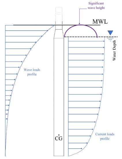
Figure 9.
Schematic representation of a FOWT platform with structural properties and environmental loading parameters systems [72].
One method for calculating hydrodynamic load in the time domain is the linear hydrodynamic model, which solves the linearized governing boundary-value problems independent of a platform’s shape, size, or type of motion. The model divides the hydrodynamic problem into three easier problems, namely the radiation, diffraction, and hydrostatic problems [91,92]. The radiation problem studies the forces that a body experiences due to the radiated wave that results from the oscillating body in the absence of an incident wave and includes contributions from wave-radiation damping and added mass [93]. The diffraction problem takes the loads on a fixed body into account when the incident waves are scattered by the body. Wave scattering and the undisturbed pressure field cause the diffraction loads (Froude–Kriloff). The hydrostatic problem calculates the forces acting on a body caused by hydrostatic pressure variations on the wetted surface area as it displaces from its equilibrium position.
The hydrodynamic force on a floating platform () can be shown as follows [54]:
Here, subscripts i and j represent the support platform degrees of freedom (1 = surge, 2 = sway, 3 = heave, 4 = roll, 5 = pitch and 6 = yaw). is the water density, g is the gravitational acceleration, is the displaced volume of fluid for an undisplaced FOWT system, is the Kronecker–Delta function component, is the linear hydrostatic-restoring matrix component determined from the effects of the water-plane area and the center of buoyancy (COB), and is the support platform’s displacement.
The first term on the right-hand side, , is the wave-induced excitation force on the support platform which is highly dependent on the wave elevation, . The wave elevation is estimated by the linear (Airy wave theory) and nonlinear wave theories. The Airy wave theory is based on mass balance and momentum balance equations, which can be expressed in terms of the velocity’s potential function, leading to the Laplace and Bernoulli equations. The second and third terms on the right-hand side, and , represent the hydrostatic loads acting on the support structure. The second term, , indicates the buoyancy force obtained from Archimedes’ principle, which acts in a vertical upward direction and is equal to the weight of the displaced water for the undisplaced FOWT. This force is only nonzero for the heave mode of displacement of the support platform. The third term, , represents the variation in the hydrostatic force and moment as the support platform is displaced. The last term on the right-hand side, , is a convolution integral that represents the load contribution from wave-radiation damping and an additional contribution from the added mass.
In order to compute the hydrodynamic coefficients and wave forces in the time-domain, first the linear hydrodynamic formulation should be obtained in the frequency domain. Commercial software, such as WAMIT (Wave Analysis at MIT) [94], Ansys AQWA [95], and SESAM [96], are widely used to solve the linearized hydrodynamic radiation and diffraction problems for the interaction of surface waves with offshore platforms of arbitrary geometry in the frequency domain. The outputs of these codes are the wave excitation force, restoring, damping, and added-mass matrices. There are also some other widely accepted open access codes, such as FinGreen3D [97] and HAMS [98], which have been developed and tested for the wave hydrodynamics calculations for the floating structures. The latter is also used as the hydrodynamic module of NREL’s response amplitudes of floating turbines (RAFT) code [99], which is a frequency-domain dynamics model for floating wind turbine systems.
The Morison equation and the frequency-domain model are the two most frequently used substitutes for the linear hydrodynamic model. The Morison equation is valid for slender structures, whose dimension is small compared to the wavelength. As Faltinsen [91] proposed, a structure can be considered slender if , where represents the characteristic diameter of the structure and is the wavelength. To put it differently, the presence of the structure does not affect the wave profile remarkably. The frequency-domain model uses the same assumptions as those in the linear hydrodynamics approach with some limitations: the propagation of the incident wave is limited to a single direction, frequency, and amplitude. In other words, the wave must be a monochromatic wave, and the platform must oscillate at the incident wave frequency. Under irregular sea states, however, it is possible to combine the results for each frequency/direction to predict the behavior of the system.
The Morison equation combined with the panel method and the pressure integration method can also be used to determine hydrodynamic forces acting on a floating platform. The structure can be divided into a number of elements using the panel method [100], while the Morison equation computes nonlinear viscous drag and linear wave loads on each element [54]. However, for floating structures with complex geometry such as semisubmersibles and TLPs, the implementation of the panel method can be tricky as the orientation and diameters of the structural members of the floater are different. This problem can be addressed using the advanced hybrid panel-stick method based on matrix operations in both the frequency [101] and time domains [48].
For a FOWT, the instantaneous position of the system should be considered to update the hydrodynamic forces on the structure in time, so the Morison equation should be modified to take into account the displacement of element as a result of the whole system’s motion [91]:
where, is the diamater of the cylindrical platform, c and u are the current and wave particle velocities, respectively, and are the structure’s velocity and acceleration, respectively, is the spar’s cross-sectional area, is the local acceleration of the wave particles, and is the spar section’s unit length.
, and are the empirically determined coefficients for viscous drag, inertia, and additional mass, respectively [102]. These coefficients are functions of the Reynolds number, relative current number, Kaulegan–Carpenter number, and surface roughness ratio [103]. In this notation of the Morison equation, the first term is the quadratic viscous drag force, and the last three terms represent the added mass, diffraction, and the Froude–Krylov forces, respectively.
3.3. Mooring System Loads
Mooring systems are used to keep the floating platform in position against waves, winds, and currents in order to limit the influence of system displacements on power production. They are also used to achieve stability in some support platform concepts, such as TLPs [54]. FOWTs typically use one of the three conventional mooring configurations, catenary mooring systems, tension-leg mooring systems, and semi-taut mooring systems, or a combination of them (Figure 10), which were initially developed with respect to the needs in the oil and gas sector [104].
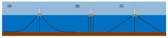
Figure 10.
Three types of mooring systems: (A) catenary mooring system, (B) tension-leg mooring system, and (C) semi-taut mooring system [105].
A mooring system consists of a number of slack or taut cables that are fastened to the floating support structure’s fairlead points and anchored to the seabed from the opposite ends. The mooring system introduces constraining forces at the fairlead points through the tension in the mooring lines, which is non-linear, and a function of position and time. The tension is dependent on the mooring system’s geometrical configuration, the cable’s apparent weight, the support platform’s motion, cable’s elasticity, and viscous separation effects.
The mooring loads are usually calculated via the finite element or non-linear spring models [106]. The drag forces may contribute to the damping effect on the platform motions. It is possible to describe the mooring lines as a quasi-static or non-linear spring to determine the dynamic response of the FOWT system, provided that the damping effects and inertia of the mooring lines are minimal in comparison to the entire FOWT system.
The quasi-static method can be used to estimate the tension on the cable by assuming a static equilibrium at each time step. The quasi-static technique ignores the inertia and damping of the mooring system, as well as the individual line bending stiffness, while accounting for elastic stretching, the cable’s weight in water, and seabed friction. Nonetheless, the nonlinear geometric restoration of the whole mooring system is considered [107]. In the quasi-static approach, two nonlinear equations can be solved using a root-finding technique to determine the vertical and horizontal components of the mooring line’s effective tension when the fairlead’s position is known at any instant.
3.4. Ice Loads
The installation of wind turbines in regions with significant ice formation has become inevitable as the global investment in offshore wind projects rises. For Arctic operations such as offshore wind generation, marine transportation, and offshore drilling to be safer and more sustainable, it is crucial to understand the sea level’s ice loading and behavior [108].
Ice loads can be examined in accordance with a variety of standards, including ISO/FDIS 19906 [109] and IEC 61400 [110], depending on the application. However, these standards only offer a general framework for including ice loads in the design and analysis process, and the specifics of ice load modeling are not specified.
The ice failure process is used to determine the loads’ amplitude and frequency. Therefore, understanding how the ice fails under a given condition is essential for determining the load and related response. After the failure process is determined, a computational model can be used to estimate the loads on the structure for different ice thicknesses. Ice failure under compression can happen in a number of ways depending on the geometry of the structure, the presence of ridges, and ice-related factors, including velocity, thickness, and temperature [111]. For sea ice, probable failure modes include creep, crushing, bending, buckling, and splitting. Bending is the main mode of failure when the level ice collides with FOWT support platforms with a conical shape, and the ice tensile strength is less than the compressive strength at the mean sea level [109,112,113,114]. For sloped structures, the impact of rubble ice accumulation might be troublesome since it can create a vertical surface against which the ice will start to crack due to crushing, resulting in an increased load.
There are several approaches to determine the ice’s impact on conical structures. ISO 19906 examined two empirical approaches: an elastic-beam-on-elastic foundation approach [115], and a plasticity-based approach [116]. In the elastic-beam-on-elastic foundation method, the horizontal component of the flexural ice failure load, , is given by:
where represents the breaking load, is the load required to push the incoming ice sheet through the rubble, is the component of the action required to push the ice blocks up the slope, is the magnitude of force needed to lift the ice rubble on top of the advancing ice sheet, and is the force required to turn the ice blocks at the transition between the conical and upper cylindrical surfaces.
Another major source of ice failure load on offshore support structures is the crushing failure. The IEC standard suggests the Korzhavin formulation [117] to estimate the limit force induced by the crushing of ice on a vertical structure, P:
where w is the structure’s projected width, h is the ice’s thickness, is the crushing strength of the ice, and , , are the shape, contact and aspect ratio factors, respectively.
The ISO 19906 standard proposes a method for the calculation of the crushing ice forces that relies on empirically-derived corrections applied to a reference strength. For ice crushing, the global limit load is given by:
where is the global average ice pressure, h is the ice’s thickness, and w is the projected width of the structure.
Several improvements have been made to the earlier developed ship-ice interaction models [118] for their application to offshore wind turbines. This approach assumes that the support platform forms the hard boundary condition for ice during the ice breaking process, particularly at the surrounding region of the waterline, since the waterline always breaks the ice when the structure penetrates into the ice sheet.
At the contact zones along the waterline, ice wedges separate from the ice sheet as the FOWT advances. The crushing force increases with the expanding contact area, until its vertical component surpasses the ice’s bearing capacity and, at a given distance from the contact zone, causes the ice sheet to bend [119,120]. Determination of the potential contact zones for both the ice sheet and the platform requires using geometry, which involves the detection of any contact (or overlap) between the FOWT’s waterline and the level ice edge. When defining this surface to represent the waterline geometry, the fluctuations owing to the wind turbine motion in six degrees of freedom are taken into account, and the geometry is identified by determining the point where the platform meets the water plane. In this approach, the contact surface between the ice and the wind turbine platform is considered to be flat at each contact zone, as indicated in Figure 11.
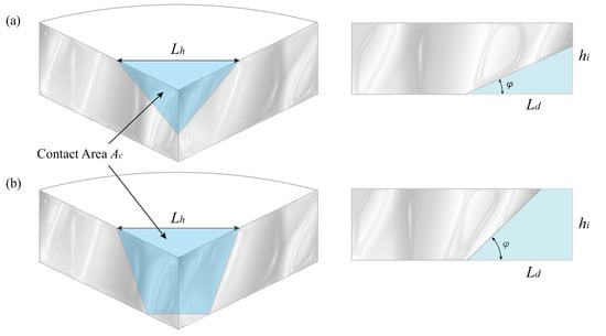
Figure 11.
Contact area representation for two different (a) and, (b) cases.
The contact area, , is defined by the indentation depth, . The contact length, , is determined by the distance between adjacent platform nodes. There are two scenarios for the contact area that are investigated through the algorithm, and the ice failure can be defined based on the results. The horizontal and vertical components of the contact force are then computed considering the contact area and the effective ice crushing and bending strengths. With the calculation of the contact force on the support structure of the offshore wind turbine, the dynamic response of the system subjected to ice loads can be determined.
3.5. Inertial Loads
The inertial forces caused by a turbine’s acceleration and deceleration include gyroscopic, centrifugal, Coriolis, hinge-spring, and braking loads. The centrifugal loads are induced by the rotation of the blade. For a backward pre-coned rotor, the component of the centrifugal force that is perpendicular to the axis of rotation induces a flapwise bending moment in the opposite direction to the thrust bending moment, which reduces the overall flapwise bending moment and causes the blade to flap back into the rotation plane.
The centrifugal force is a function of the distance to the rotation axis and the square of the rotational velocity. In most cases, the Coriolis force experienced by moving objects in a reference frame that spins with regard to an inertial frame, such as the Earth, is insignificant. The gyroscopic loads on the rotor occur when the turbine yaws in operational mode, creating a yaw moment about the vertical axis and a tilting moment about the horizontal axis in the plane of rotation, as shown in Figure 12.
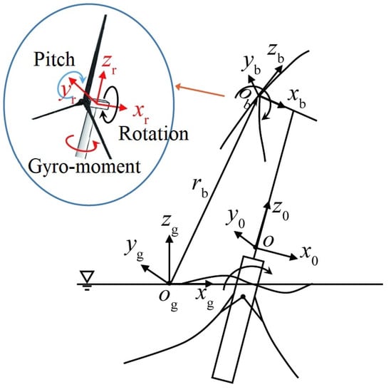
Figure 12.
Gyroscopic effect on a FOWT [121].
To bring the blade back into the hinge’s plane, the hinge-spring creates a moment at the hinge with an amplitude equal to the flapping angle. When a braking torque is applied to the rotor shaft, mechanical braking loads occur, leading to a rotor deceleration and, consequently, edgewise bending moments.
4. Numerical Models to Simulate the Dynamics of FOWTs
The design of a FOWT calls for a multidisciplinary approach for assessing a range of interrelated modules, including hydrodynamics, aerodynamics, and structural dynamics and controls, making it one of the most difficult and complex offshore structures [45,122]. Therefore, offshore floating wind turbines are analyzed and designed by implementing fully coupled dynamic response simulation tools.
For the onshore wind turbine analysis, aero-servo-elastic codes are widely used, which integrate the aerodynamic (aero), controller system (servo) and structural dynamic (elastic) modules in a fully coupled manner. During the last decade, some of these algorithms have been enhanced to include additional offshore deployment dynamics, such as the sea current, wave loads, hydrodynamic loads, level ice loads, and support structure dynamics. Most of the well-known aero-hydro-servo-elastic simulation tools that are currently available are listed in Table 1.

Table 1.
Overview of aero-servo-hydro-elastic numerical models and their capabilities and limitations.
Each code has its own set of advantages and disadvantages related to the trade-off between the accuracy and simulation time. All numerical tools presented in Table 1 use the fully coupled approach in load prediction. SIMPACK, Simo, SESAM/DeepC, FAST, BA-Simula, Adams, and all versions of HAWC, FLEX5, and Bladed use a multi-body system (MBS) to determine the structural dynamics. Here, a multi-body system is defined as the spatial arrangement of a set of flexible or rigid bodies with respect to global and local coordinate systems, which is further detailed in [144]. Except ANSYS-WaveLoads and SESAM/DeepC, the BEM method is implemented to calculate the aerodynamic force, including dynamic stall and dynamic wake. Dynamic stall is implemented by using the Beddoes–Leishman model [139]. The free vortex wake (FVW) method is preferred to simulate the impacts of dynamic inflow skewed wake, tip losses, and ground effects for large wind turbines. However, the majority of the codes presented here include a generalized dynamic wake (GDW) solver based on potential methods, which can be considered as one of the shortcomings of these tools.
There are a number of factors that must be taken into account in order to carry out a reliable hydrodynamic assessment of FOWT systems, including wave loads, station-keeping, current loads, stability, and damping. Except for SIMPACK, all of the codes presented here calculate hydrodynamic forces on the floater using a combination of linear (Airy) wave theory, potential theory and/or Morison’s equation. Linear wave theory gives a linearized description of the propagation of surface gravity waves and is strictly applicable to conditions in which the wave height is small compared to the wavelength and the water depth. Potential theory is deemed more suitable for big volume models, where the floater is modeled as a three-dimensional diffracting body and the wave-induced loads acting on the platform are determined via panel method [145]. Morison’s equation is applicable to slender structures and takes into account the floater’s diameter, fluid particle velocity and acceleration, as well as the hydrodynamic drag and inertia coefficients [91]. However, there is a number of drawbacks, where the wave radiation damping and some terms of the additional mass matrix are neglected and the diffraction problem is oversimplified.
5. Experimental Models to Simulate the Dynamics of FOWTs
Physical modeling has been widely used for determining the wave- and current-induced response of floating offshore platforms in order to assess the feasibility of implementing such systems and to calibrate and validate numerical models. However, building a scaled model of an operational wind turbine mounted on a floating platform is not achievable because the Reynolds number scaling of the aerodynamic loads and the Froude number scaling of the hydrodynamic loads cannot be satisfied simultaneously [146].
The first physical model test was conducted by the DeepCwind association, where the experimental data for a spar [147], semi-submersible [148], and tension leg platform [149,150,151] were compared with the data from the NREL FAST numerical model. The results demonstrated that a geometrically scaled rotor did not accurately mimic the aerodynamic capabilities of a real-life rotor. The second test was conducted using a performance-scaled rotor, which had a steady thrust-matched design that provided the necessary thrust without satisfying the Reynolds number scaling [150,151]. However, reproducing the expected aerodynamic loads at low Reynolds numbers was still an issue due to the Froude number scaling [152]. In order to resolve this conflict, testing methods such as software-in-the-loop (SIL) and hardware-in-the-loop (HIL) have been developed, where the scaled wind turbine rotor is replaced with a system that is capable of generating equal aerodynamic loads [153]. SIL and HIL methods make it possible to study the fully coupled dynamic response of FOWTs in both wave basins and wind tunnels by enhancing the accuracy of scale model tests. In these methods, the aerodynamic loads on the rotor are often calculated using a numerical model that incorporates the instantaneous displacements of the floating platform as an input. These loads are, then, applied to the physical model by utilizing devices such as winches [154], tendons [155,156], ducted fans [157,158], or multi-fans [159]. Another fully coupled experimental FOWT dynamic response analysis has recently been conducted in the wind tunnel of Politecnico di Milano, where a scaled wind turbine model was used to generate proper aerodynamic loads. A numerical hydrodynamic and mooring system model that used the aerodynamic forces acting on the tower base as an input was, then, coupled with the physical wind turbine [160,161].
6. Machine Learning Models in FOWTs’ Design, Monitoring and Analysis
The assessment of FOWTs’ dynamic performance using numerical simulation tools is usually time consuming because large sets of load scenarios are needed [162,163]. The implementation of numerical methods such as CFD tools requires a great deal of insight into the physical processes governing the behavior of FOWTs. To address these problems, surrogate models have been proposed and tested, which showed their capability of reducing runtime while preserving accuracy [164,165]. Surrogate models can be divided into two general categories, namely, data-driven and projection-based methods.
Data-driven methods such as Gaussian processes [166,167], support-vector networks [168], Wiener chaos expansion [169], decision networks [170,171], radial basis functions [172], dynamic mode decomposition [173], and neural networks [174,175] can model the dynamic response of the system by finding the relevancy between the model inputs and outputs based on the numerical simulation data. On the other hand, projection methods such as dynamic mode decomposition [176], the reduced basis method [177,178], Kosambi–-Karhunen–-Loève theorem [176], proper orthogonal decomposition [179,180], and proper generalized decomposition [181,182] are effective means of numerically solving time-dependent incompressible fluid-flow problems by projecting the governing equations of the system onto a reduced-dimension subspace.
Data-driven and projection-based methods both have advantages and disadvantages. The projection-based approach is proven to be accurate in predicting the outcome of the test input data that are never used in model training but is also prone to loss of the crucial physical properties of the underlying dynamics due to the reduction of the original space dimension. The fundamental benefit of data-driven techniques is that the model behaves similar to a black box and there is no requirement to understand the underlying system. However, the performance of these models is highly dependent on the volume of training data and necessitates a relatively bigger data set to obtain accurate findings.
In recent years, machine learning (ML) and other advanced data-driven models have become more popular in the analysis of FOWT dynamics. Numerous ML algorithms, including artificial neural networks (ANNs), neuro-fuzzy, support-vector machine (SVM), and support-vector regression (SVR), have shown promising results for both short- and long-term time series prediction [183,184,185,186,187,188]. With the advent of GPU parallel computing, deep learning neural networks (DLNNs) have attracted a lot of attention and have been used in numerous sectors of maritime engineering since 2012. DLNNs can automatically learn arbitrary complex mappings between the inputs and outputs while handling multiple data, which makes them strong tools for time series forecasting, especially in situations with complex-nonlinear dependencies, multivalent inputs, and multi-step forecasting [189]. In this regard, the recurrent neural network (RNN) is a promising deep learning technique that can be used to predict the structural responses of FOWT systems. In this network, the connections between the neural nodes create a cycle, allowing the output from some nodes to affect the subsequent input of the same nodes [190,191]. A previous study included two different RNN models, gated recurrent unit (GRU), and long short-term memory (LSTM) neural networks that were used to detect the structural damage of FOWT blades [192]. Another study linearized structural properties of a FOWT to apply them as the physical constraints to a deep residual recurrent neural network (DR-RNN) to form a deep learning framework [193]. This model was introduced to a frame structure with four degrees of freedom as a benchmark study for validation purposes, and the results were compared with a classic data-driven model. The proposed model provided robust system dynamic response predictions regardless of the range of original training data. A different study implemented DLNN to predict the dynamic response of FOWT towers, where the outputs of the OpenFAST numerical tool were used to train a multi-layer perception (MLP) model [194]. The model demonstrated a promising performance in the assessment of the tower top accelerations and tower base forces. A convolutional neural network (CNN) was proposed to monitor the structural health of the wind turbines. The proposed model was fed with wind turbine tower vibration data, which was calculated using the NREL FAST code for a variety of wind turbulence intensity (WTI) levels and blade health conditions [195]. The CNN provided satisfactory results in predicting the defective blade effect on tower vibrations. A DLNN model was trained using the FOWT mooring loads data derived from a fully coupled aero-hydro-servo-elastic numerical model and a finite element model [196]. A feedforward neural network with five layers was used to predict the mooring line tension for a range of load scenarios and a good agreement between the results of the DLNN and numerical models was achieved. Another study implemented an RNN model to assess the wind turbine’s sequential condition monitoring data, and the model performance verification was performed against a real-world wind turbine condition monitoring data set [197].
7. Summary and Expected Future Developments of FOWTs
Policymakers have started to recognize global warming as a serious threat to life on earth in the forms of widespread flooding and extreme weather. There is a narrowing window of time to act decisively to halt global warming. The urgency and demand for clean renewable energy have accelerated the development of FOWTs in recent years, and advancements and new designs are expected to continue. However, the harsh environment of oceans and the complexity of the design and installation of FOWTs have been a grand challenge for offshore engineers. The present work has provided a comprehensive overview of the recent developments in FOWT design concepts, physics of various disciplines governing the dynamics behavior, and numerical models to simulate the offshore wind turbines.
The majority of the world’s usable offshore wind resources exist at depths greater than 60 m, which is highly encouraging from an economic standpoint for the development of floating offshore wind technology. The placement of turbines adjacent to one another can modify the wind flow and cause wake effects, which is one of the challenges that offshore wind farms must overcome. Due to the downstream wind speed drop brought on by the wind turbines being so close to one another, less power is produced by the farm. Optimizing wind farms for a variety of environmental load scenarios while minimizing the potential wake effects in real time requires up to thousands of iterations and simulation runs, which is considerably expensive and time consuming. In this regard, the most recent development is an AI framework that develops physics-informed machine learning models, enabling up to 4000 times faster high-fidelity simulations than that of traditional methods [198].
Another cutting-edge alternative is the OceanHydro Omni, which seeks to address the primary problems associated with conventional horizontal axis offshore wind turbines [199]. In addition to the wake effect, horizontal axis wind turbines can only function within a specified range of wind speed, preventing them from utilizing the full potential of the wind. The stochastic nature of the wind is the other significant issue, which causes unpredictable fluctuations in electricity generation. Vertical axis offshore wind turbines, on the other hand, can be installed relatively closer together because they generate a funnel-shaped wake that stretches similar to a contrail, reducing the turbulence of the wind. The disadvantage of vertical axis wind turbines is that their efficiency ranges between and , which is significantly lower than the efficiency of horizontal axis turbines. OceanHydro Omni utilizes a vertical axis wind rotor that provides mechanical power to lift a heavy block which is, then, released to generate electricity through an electrical generator. Omni is also capable of providing an electrical conversion efficiency of up to with the added benefit of on-demand dispatchable power and energy storage. It is designed to stay operational during high wind speeds (up to 40 m/s). As of right now, the technical preparedness is not fulfilled; however, there is still much potential for development and research on this concept.
To summarize, remarkable progress has been made in the recent decades in the development of new floating platform design concepts and numerical models to simulate the dynamic response of the offshore wind turbines. However, FOWTs are yet in their preliminary stage of technology readiness, and further development and research are required to better understand their dynamic response for more cost-effective designs.
Author Contributions
Conceptualization, M.B. and T.A.; methodology, M.B. and D.V.S.; investigation, M.B., S.G.T. and D.V.S.; resources, S.W.; data curation, S.G.T.; writing—original draft preparation, M.B.; writing—review and editing, D.V.S. and T.A.; visualization, S.G.T.; supervision, D.V.S.; funding acquisition, D.V.S. All authors have read and agreed to the published version of the manuscript.
Funding
Publication of this article was funded by the Open Access Subvention Fund and the John H. Evans Library and Florida Institute of Technology Ocean Engineering and Marine Sciences Department.
Data Availability Statement
Not applicable.
Conflicts of Interest
The authors declare no conflict of interest.
References
- Al-Ghussain, L. Global warming: Review on driving forces and mitigation. Environ. Prog. Sustain. Energy 2019, 38, 13–21. [Google Scholar] [CrossRef]
- Sun, X.; Huang, D.; Wu, G. The current state of offshore wind energy technology development. Energy 2012, 41, 298–312. [Google Scholar] [CrossRef]
- Benson, C.L.; Magee, C.L. On improvement rates for renewable energy technologies: Solar PV, wind turbines, capacitors, and batteries. Renew. Energy 2014, 68, 745–751. [Google Scholar] [CrossRef]
- Kim, C.; Dinh, M.C.; Sung, H.J.; Kim, K.H.; Choi, J.H.; Graber, L.; Yu, I.K.; Park, M. Design, Implementation, and Evaluation of an Output Prediction Model of the 10 MW Floating Offshore Wind Turbine for a Digital Twin. Energies 2022, 15, 6329. [Google Scholar] [CrossRef]
- Ashuri, T.; Zaayer, M. Review of design concepts, methods and considerations of offshore wind turbines. In Proceedings of the 2007 European Offshore Wind Conference and Exhibition, Berlin, Germany, 4–6 December 2007; European Wind Energy Association EWEA: Brussels, Belgium, 2007. [Google Scholar]
- Global Wind Energy Council. Wind Report 2021; Global Wind Energy Council: Brussels, Belgium, 9 September 2021. [Google Scholar]
- Da, Z.; Xiliang, Z.; Jiankun, H.; Qimin, C. Offshore wind energy development in China: Current status and future perspective. Renew. Sustain. Energy Rev. 2011, 15, 4673–4684. [Google Scholar] [CrossRef]
- Musial, W.; Spitsen, P.; Beiter, P.; Duffy, P.; Marquis, M.; Cooperman, A.; Hammond, R.; Shields, M. Offshore Wind Market Report: 2021 Edition; Department of Energy: Washington, DC, USA, 2021. [Google Scholar]
- O’Kelly, B.; Arshad, M. Offshore wind turbine foundations–analysis and design. In Offshore Wind Farms; Elsevier: Amsterdam, The Netherlands, 2016; pp. 589–610. [Google Scholar]
- Castro-Santos, L.; Diaz-Casas, V. Floating Offshore Wind Farms; Springer: Berlin/Heidelberg, Germany, 2016. [Google Scholar]
- Savenije, L.; Ashuri, T.; Bussel, G.; Staerdahl, J. Dynamic modeling of a spar-type floating offshore wind turbine. In Proceedings of the European Wind Energy Conference and Exhibition (EWEC), Warsaw, Poland, 20–23 April 2010; pp. 1–10. [Google Scholar]
- Ashuri, T. Beyond Classical Upscaling: Integrated Aeroservoelastic Design And Optimization of Large Offshore Wind Turbines. Ph.D. Thesis, Delft University of Technology, Delft, The Netherlands, 2012. [Google Scholar]
- Stehly, T.; Beiter, P.; Duffy, P. 2019 Cost of Wind Energy Review; Technical Report; National Renewable Energy Lab. (NREL): Golden, CO, USA, 2020. [Google Scholar]
- Ashuri, T.; Vasquez Mayen, E.; Hamidi, R. A new statistical approach to enhance the performance of model-free optimal controls algorithms. In Proceedings of the 2018 Multidisciplinary Analysis and Optimization Conference, Atlanta, Georgia, 25–29 June 2018; p. 3421. [Google Scholar]
- Kong, X.; Ma, L.; Liu, X.; Abdelbaky, M.A.; Wu, Q. Wind turbine control using nonlinear economic model predictive control over all operating regions. Energies 2020, 13, 184. [Google Scholar] [CrossRef]
- Shah, K.A.; Meng, F.; Li, Y.; Nagamune, R.; Zhou, Y.; Ren, Z.; Jiang, Z. A synthesis of feasible control methods for floating offshore wind turbine system dynamics. Renew. Sustain. Energy Rev. 2021, 151, 111525. [Google Scholar] [CrossRef]
- Ashuri, T.; Martins, J.R.; Zaaijer, M.B.; van Kuik, G.A.; van Bussel, G.J. Aeroservoelastic design definition of a 20 MW common research wind turbine model. Wind Energy 2016, 19, 2071–2087. [Google Scholar] [CrossRef]
- Gaertner, E.; Rinker, J.; Sethuraman, L.; Zahle, F.; Anderson, B.; Barter, G.E.; Abbas, N.J.; Meng, F.; Bortolotti, P.; Skrzypinski, W.; et al. IEA Wind TCP Task 37: Definition of the IEA 15-Megawatt Offshore Reference Wind Turbine; Technical Report; National Renewable Energy Lab. (NREL): Golden, CO, USA, 2020. [Google Scholar]
- Madsen, M.H.A.; Zahle, F.; Sørensen, N.N.; Martins, J.R. Multipoint high-fidelity CFD-based aerodynamic shape optimization of a 10 MW wind turbine. Wind Energy Sci. 2019, 4, 163–192. [Google Scholar] [CrossRef]
- Dhert, T.; Ashuri, T.; Martins, J.R. Aerodynamic shape optimization of wind turbine blades using a Reynolds-averaged Navier–Stokes model and an adjoint method. Wind Energy 2017, 20, 909–926. [Google Scholar] [CrossRef]
- Ardente, F.; Beccali, M.; Cellura, M.; Brano, V.L. Energy performances and life cycle assessment of an Italian wind farm. Renew. Sustain. Energy Rev. 2008, 12, 200–217. [Google Scholar] [CrossRef]
- uit het Broek, M.A.; Veldman, J.; Fazi, S.; Greijdanus, R. Evaluating resource sharing for offshore wind farm maintenance: The case of jack-up vessels. Renew. Sustain. Energy Rev. 2019, 109, 619–632. [Google Scholar] [CrossRef]
- Ashuri, T.; Ponnurangam, C.; Zhang, J.; Rotea, M. Integrated layout and support structure optimization for offshore wind farm design. J. Phys. Conf. Ser. 2016, 753, 092011. [Google Scholar] [CrossRef]
- Ramos-García, N.; Kontos, S.; Pegalajar-Jurado, A.; González Horcas, S.; Bredmose, H. Investigation of the floating IEA Wind 15 MW RWT using vortex methods Part I: Flow regimes and wake recovery. Wind Energy 2022, 25, 468–504. [Google Scholar] [CrossRef]
- Ashuri, T.; Li, Y.; Hosseini, S.E. Recovery of energy losses using an online data-driven optimization technique. Energy Convers. Manag. 2020, 225, 113339. [Google Scholar] [CrossRef]
- Ashuri, T.; Rotea, M.; Xiao, Y.; Li, Y.; Ponnurangam, C.V. Wind turbine performance decline and its mitigation via extremum seeking controls. In Proceedings of the AIAA Science and Technology Forum and Exposition (SciTech), Wind Energy Symposium, San Diego, CA, USA, 3–7 January 2022; American Institute of Aeronautics and Astronautics: Reston, VA, USA, 2016; pp. 1–11. [Google Scholar]
- McWilliam, M.K.; Zahle, F.; Dicholkar, A.; Verelst, D.; Kim, T. Optimal aero-elastic design of a rotor with bend-twist coupling. J. Phys. Conf. Ser. 2018, 1037, 042009. [Google Scholar] [CrossRef]
- Neto, J.X.V.; Junior, E.J.G.; Moreno, S.R.; Ayala, H.V.H.; Mariani, V.C.; dos Santos Coelho, L. Wind turbine blade geometry design based on multi-objective optimization using metaheuristics. Energy 2018, 162, 645–658. [Google Scholar] [CrossRef]
- Kitzing, L.; Morthorst, P.E. Trends in offshore wind economics–the past and the future. In Proceedings of the 14th Wind Integration Workshop, Bruessels, Belgium, 20–22 October 2015; pp. 20–22. [Google Scholar]
- Morthorst, P.E.; Kitzing, L. Economics of building and operating offshore wind farms. In Offshore Wind Farms; Elsevier: Amsterdam, The Netherlands, 2016; pp. 9–27. [Google Scholar]
- Mone, C.; Hand, M.; Bolinger, M.; Rand, J.; Heimiller, D.; Ho, J. 2015 Cost of Wind Energy Review; Technical Report; National Renewable Energy Lab. (NREL): Golden, CO, USA, 2017. [Google Scholar]
- Díaz, H.; Soares, C.G. Review of the current status, technology and future trends of offshore wind farms. Ocean. Eng. 2020, 209, 107381. [Google Scholar] [CrossRef]
- Arapogianni, A.; Genachte, A.B.; Ochagavia, R.M.; Vergara, J.P.; Castell, D.; Tsouroukdissian, A.R.; Korbijn, J.; Bolleman, N.; Huera-Huarte, F.J.; Schuon, F.; et al. Deep Water—The Next Step for Offshore Wind Energy; European Wind Energy Association (EWEA): Brussels, Belgium, 2013; pp. 972–978. [Google Scholar]
- Mills, S.B.; Bessette, D.; Smith, H. Exploring landowners’ post-construction changes in perceptions of wind energy in Michigan. Land Use Policy 2019, 82, 754–762. [Google Scholar] [CrossRef]
- Schallenberg-Rodríguez, J.; Montesdeoca, N.G. Spatial planning to estimate the offshore wind energy potential in coastal regions and islands. Practical case: The Canary Islands. Energy 2018, 143, 91–103. [Google Scholar] [CrossRef]
- Nematbakhsh, A.; Olinger, D.J.; Tryggvason, G. A nonlinear computational model of floating wind turbines. J. Fluids Eng. 2013, 135, 121103. [Google Scholar] [CrossRef]
- Castro-Santos, L.; Filgueira-Vizoso, A.; Carral-Couce, L.; Formoso, J.Á.F. Economic feasibility of floating offshore wind farms. Energy 2016, 112, 868–882. [Google Scholar] [CrossRef]
- Schwanitz, V.J.; Wierling, A. Offshore wind investments–realism about cost developments is necessary. Energy 2016, 106, 170–181. [Google Scholar] [CrossRef]
- Roddier, D.; Cermelli, C.; Weinstein, A. WINDFLOAT: A Floating Foundation for Offshore Wind Turbine Part I: Design Basis and Qualification Process. Paper No. OMAE2009-79229. In Proceedings of the 28th International Conference on Offshore Mechanics and Arctic Engineering, Honolulu, HI, USA, 31 May–5 June 2009; p. V010T09A073. [Google Scholar]
- Mei, X.; Xiong, M. Effects of second-order hydrodynamics on the dynamic responses and fatigue damage of a 15 MW floating offshore wind turbine. J. Mar. Sci. Eng. 2021, 9, 1232. [Google Scholar] [CrossRef]
- Cottura, L.; Caradonna, R.; Novo, R.; Ghigo, A.; Bracco, G.; Mattiazzo, G. Effect of pitching motion on production in a OFWT. J. Ocean. Eng. Mar. Energy 2022, 8, 319–330. [Google Scholar] [CrossRef]
- Hu, D.; Deng, L.; Zeng, L. Study on the Aerodynamic Performance of Floating Offshore Wind Turbine Considering the Tower Shadow Effect. Processes 2021, 9, 1047. [Google Scholar] [CrossRef]
- Maienza, C.; Avossa, A.; Ricciardelli, F.; Coiro, D.; Troise, G.; Georgakis, C.T. A life cycle cost model for floating offshore wind farms. Appl. Energy 2020, 266, 114716. [Google Scholar] [CrossRef]
- Zheng, Z.; Chen, J.; Liang, H.; Zhao, Y.; Shao, Y. Hydrodynamic responses of a 6 MW spar-type floating offshore wind turbine in regular waves and uniform current. Fluids 2020, 5, 187. [Google Scholar] [CrossRef]
- Nielsen, F.G.; Hanson, T.D.; Skaare, B. Integrated dynamic analysis of floating offshore wind turbines. In Proceedings of the International Conference on Offshore Mechanics and Arctic Engineering, Hamburg, Germany, 4–9 June 2006; Volume 47462, pp. 671–679. [Google Scholar]
- Lefebvre, S.; Collu, M. Preliminary design of a floating support structure for a 5 MW offshore wind turbine. Ocean. Eng. 2012, 40, 15–26. [Google Scholar] [CrossRef]
- Johannessen, M. Concept Study and Design of Floating Offshore Wind Turbine Support Structure. Master’s Thesis, KTH, School of Engineering Sciences (SCI), Aeronautical and Vehicle Engineering, Naval Systems, Stockholm, Sweden, 2018. [Google Scholar]
- Liu, Y.; Hu, C.; Sueyoshi, M.; Yoshida, S.; Iwashita, H.; Kashiwagi, M. Motion response characteristics of a Kyushu-University semi-submersible Floating Wind Turbine with trussed slender structures: Experiment vs. numerical simulation. Ocean. Eng. 2021, 232, 109078. [Google Scholar] [CrossRef]
- Ahn, H.; Ha, Y.J.; Cho, S.g.; Lim, C.H.; Kim, K.H. A Numerical Study on the Performance Evaluation of a Semi-Type Floating Offshore Wind Turbine System According to the Direction of the Incoming Waves. Energies 2022, 15, 5485. [Google Scholar] [CrossRef]
- Benitz, M.A.; Schmidt, D.P.; Lackner, M.A.; Stewart, G.M.; Jonkman, J.; Robertson, A. Comparison of hydrodynamic load predictions between reduced order engineering models and computational fluid dynamics for the oc4-deepcwind semi-submersible. In Proceedings of the 2014 International Conference on Offshore Mechanics and Arctic Engineering, San Francisco, CA, USA, 8–13 June 2014; American Society of Mechanical Engineers: New York, NY, USA, 2014; Volume 45547, p. V09BT09A006. [Google Scholar]
- James, R.; Weng, W.Y.; Spradbery, C.; Jones, J.; Matha, D.; Mitzlaff, A.; Ahilan, R.; Frampton, M.; Lopes, M. Floating Wind Joint Industry Project—Phase I Summary Report. Carbon Trust Tech. Rep. 2018, 19, 2–20. [Google Scholar]
- Van Kessel, J.L.F. Aircushion Supported Mega-Floaters. Ph.D. Thesis, Delft University of Technology, Delft, The Netherlands, 2010. [Google Scholar]
- Jonkman, J.; Buhl, M. Loads Analysis of a Floating Offshore Wind Turbine Using Fully Coupled Simulation; No. NREL/CP-500-41714, Technical Report; National Renewable Energy Lab. (NREL): Golden, CO, USA, 2007. [Google Scholar]
- Jonkman, J.M. Dynamics Modeling and Loads Analysis of an Offshore Floating Wind Turbine; University of Colorado at Boulder: Boulder, CO, USA, 2007. [Google Scholar]
- Adam, F.; Myland, T.; Dahlhaus, F.; Großmann, J. Gicon®-TLP for wind turbines—the path of development. In Proceedings of the The 1st International Conference on Renewable Energies Offshore (RENEW), Lisbon, Portugal, 24–26 November 2014; pp. 24–26. [Google Scholar]
- Chuang, T.C.; Yang, W.H.; Yang, R.Y. Experimental and numerical study of a barge-type FOWT platform under wind and wave load. Ocean. Eng. 2021, 230, 109015. [Google Scholar] [CrossRef]
- Atcheson, M.; Garrad, A.; Cradden, L.; Henderson, A.; Matha, D.; Nichols, J.; Roddier, D.; Sandberg, J. Floating Offshore Wind Energy; Springer: Berlin/Heidelberg, Germany, 2016. [Google Scholar]
- Fang, C.; Chan, H.; Incecik, A. Investigation of motions of catamarans in regular waves—II. Ocean. Eng. 1997, 24, 949–966. [Google Scholar] [CrossRef]
- Johlas, H.M.; Martínez-Tossas, L.A.; Churchfield, M.J.; Lackner, M.A.; Schmidt, D.P. Floating platform effects on power generation in spar and semisubmersible wind turbines. Wind Energy 2021, 24, 901–916. [Google Scholar] [CrossRef]
- Qasim, I.; Gao, L.; Peng, D.; Liu, B. Catamaran or semi-submersible for floating platform–selection of a better design. In IOP Conference Series: Earth and Environmental Science; IOP Publishing: Bristol, UK, 2018; Volume 121, p. 052041. [Google Scholar]
- Junianto, S.; Prastianto, R.W.; Wardhana, W. Motion Responses Analysis for Tidal Current Energy Platform: Quad-Spar and Catamaran Types. China Ocean. Eng. 2020, 34, 677–687. [Google Scholar] [CrossRef]
- Brown, S.; Ransley, E.; Xie, N.; Monk, K.; De Angelis, G.; Nicholls-Lee, R.; Guerrini, E.; Greaves, D. On the impact of motion-thrust coupling in floating tidal energy applications. Appl. Energy 2021, 282, 116246. [Google Scholar] [CrossRef]
- Xue, K.; Wang, W.B.; Wang, W.Y. A Dynamic Positioning Method for Single Point Mooring System of a Catamaran. In Key Engineering Materials; Trans Tech Publications Ltd.: Wollerau, Switzerland, 2011; Volume 450, pp. 47–50. [Google Scholar]
- Cutler, J.; Bashir, M.; Yang, Y.; Wang, J.; Loughney, S. Preliminary development of a novel catamaran floating offshore wind turbine platform and assessment of dynamic behaviours for intermediate water depth application. Ocean. Eng. 2022, 258, 111769. [Google Scholar] [CrossRef]
- Zhang, H.; Wang, H.; Cai, X.; Xie, J.; Wang, Y.; Zhang, N. Novel method for designing and optimising the floating platforms of offshore wind turbines. Ocean. Eng. 2022, 266, 112781. [Google Scholar] [CrossRef]
- Zhang, H.; Wang, H.; Cai, X.; Xie, J.; Wang, Y.; Zhang, N. Research on the Dynamic Performance of a Novel Floating Offshore Wind Turbine Considering the Fully-Coupled-Effect of the System. J. Mar. Sci. Eng. 2022, 10, 341. [Google Scholar] [CrossRef]
- Armesto, J.A.; Jurado, A.; Guanche, R.; Couñago, B.; Urbano, J.; Serna, J. Telwind: Numerical analysis of a floating wind turbine supported by a two bodies platform. In International Conference on Offshore Mechanics and Arctic Engineering; American Society of Mechanical Engineers: New York, NY, USA, 2018; Volume 51319, p. V010T09A073. [Google Scholar]
- Yang, Y.; Bashir, M.; Michailides, C.; Mei, X.; Wang, J.; Li, C. Coupled analysis of a 10 MW multi-body floating offshore wind turbine subjected to tendon failures. Renew. Energy 2021, 176, 89–105. [Google Scholar] [CrossRef]
- Jaksic, V.; O’Shea, R.; Cahill, P.; Murphy, J.; Mandic, D.; Pakrashi, V. Dynamic response signatures of a scaled model platform for floating wind turbines in an ocean wave basin. Philos. Trans. R. Soc. A Math. Phys. Eng. Sci. 2015, 373, 20140078. [Google Scholar] [CrossRef] [PubMed]
- Buckley, T.; Watson, P.; Cahill, P.; Jaksic, V.; Pakrashi, V. Mitigating the structural vibrations of wind turbines using tuned liquid column damper considering soil-structure interaction. Renew. Energy 2018, 120, 322–341. [Google Scholar] [CrossRef]
- Clement, C.; Kosleck, S.; Lie, T. Investigation of viscous damping effect on the coupled dynamic response of a hybrid floating platform concept for offshore wind turbines. Ocean. Eng. 2021, 225, 108836. [Google Scholar] [CrossRef]
- Barooni, M.; Ali, N.A.; Ashuri, T. An open-source comprehensive numerical model for dynamic response and loads analysis of floating offshore wind turbines. Energy 2018, 154, 442–454. [Google Scholar] [CrossRef]
- Manwell, J.F.; McGowan, J.G.; Rogers, A.L. Wind Energy Explained: Theory, Design and Application; John Wiley & Sons: Hoboken, NJ, USA, 2010. [Google Scholar]
- Glauert, H. Airplane propellers. In Aerodynamic Theory; Springer: Berlin/Heidelberg, Germany, 1935; pp. 169–360. [Google Scholar]
- Hansen, M. Aerodynamics of Wind Turbines; Routledge: London, UK, 2015. [Google Scholar]
- Glauert, M. Wind-Tunnel Tests on a Thick Suction Aerofoil with a Single Slot. 1948. Available online: https://reports.aerade.cranfield.ac.uk/handle/1826.2/3186 (accessed on 1 September 2020).
- Beltran, B.; Benbouzid, M.E.H.; Ahmed-Ali, T. Second-order sliding mode control of a doubly fed induction generator driven wind turbine. IEEE Trans. Energy Convers. 2012, 27, 261–269. [Google Scholar] [CrossRef]
- Meng, W.; Yang, Q.; Sun, Y. Guaranteed performance control of DFIG variable-speed wind turbines. IEEE Trans. Control. Syst. Technol. 2016, 24, 2215–2223. [Google Scholar] [CrossRef]
- Karman, T.V. The fundamentals of the statistical theory of turbulence. J. Aeronaut. Sci. 1937, 4, 131–138. [Google Scholar] [CrossRef]
- Jamieson, P. Generalized limits for energy extraction in a linear constant velocity flow field. Wind. Energy Int. J. Prog. Appl. Wind. Power Convers. Technol. 2008, 11, 445–457. [Google Scholar] [CrossRef]
- Liu, Y.; Yoshida, S. An extension of the Generalized Actuator Disc Theory for aerodynamic analysis of the diffuser-augmented wind turbines. Energy 2015, 93, 1852–1859. [Google Scholar] [CrossRef]
- Hansen, M.O.L.; Sørensen, J.N.; Voutsinas, S.; Sørensen, N.; Madsen, H.A. State of the art in wind turbine aerodynamics and aeroelasticity. Prog. Aerosp. Sci. 2006, 42, 285–330. [Google Scholar] [CrossRef]
- Prager, W. Die druckverteilung an körpern in ebener potentialströmung. Physik. Zeitschr 1928, 29. [Google Scholar]
- Rosenhead, L. The formation of vortices from a surface of discontinuity. Proc. R. Soc. Lond. Ser. A Contain. Pap. Math. Phys. Character 1931, 134, 170–192. [Google Scholar]
- Rosenhead, L. The point vortex approximation of a vortex sheet. Proc. Roy. Soc. London Ser. A 1932, 134, 170–192. [Google Scholar]
- Cottet, G.H.; Koumoutsakos, P.D. Vortex Methods: Theory and Practice; Cambridge University Press: Cambridge, UK, 2000; Volume 8. [Google Scholar]
- Lee, H.; Sengupta, B.; Araghizadeh, M.; Myong, R. Review of vortex methods for rotor aerodynamics and wake dynamics. Adv. Aerodyn. 2022, 4, 1–36. [Google Scholar] [CrossRef]
- Islam Md, Q.; Sadrul Islam, A.K.M. The Aerodynamic Performance of a Horizontal-Axis Wind Turbine Calculated by Strip Theory. JSME Int. J. Ser. B 1994, 37, 871–877. [Google Scholar] [CrossRef]
- Tran, T.T.; Kim, D.H. A CFD study into the influence of unsteady aerodynamic interference on wind turbine surge motion. Renew. Energy 2016, 90, 204–228. [Google Scholar] [CrossRef]
- Rezaeiha, A.; Montazeri, H.; Blocken, B. On the accuracy of turbulence models for CFD simulations of vertical axis wind turbines. Energy 2019, 180, 838–857. [Google Scholar] [CrossRef]
- Faltinsen, O. Sea Loads on Ships and Offshore Structures; Cambridge University Press: Cambridge, UK, 1993; Volume 1. [Google Scholar]
- Newman, J.N. Marine Hydrodynamics; The MIT Press: Cambridge, MA, USA, 2018. [Google Scholar]
- Falnes, J.; Kurniawan, A. Ocean Waves and Oscillating Systems: Linear Interactions Including Wave-Energy Extraction; Cambridge University Press: Cambridge, UK, 2020; Volume 8. [Google Scholar]
- Lee, C.; Newman, J. WAMIT User Manual, Version 7.0; WAMIT Inc.: Chestnut Hill, MA, USA, 2013. [Google Scholar]
- ANSYS, A. User Manual Release 15.0; ANSYS Inc.: Canonsburg, PA, USA, 2013. [Google Scholar]
- Manual, S.U. Wave and Current Loads on Fixed Rigid Frame Structures, Sesam User Manual; DNV GL: Bærum, Norway, 2021. [Google Scholar]
- Liu, Y.; Yoshida, S.; Hu, C.; Sueyoshi, M.; Sun, L.; Gao, J.; Cong, P.; He, G. A reliable open-source package for performance evaluation of floating renewable energy systems in coastal and offshore regions. Energy Convers. Manag. 2018, 174, 516–536. [Google Scholar] [CrossRef]
- Liu, Y. HAMS: A frequency-domain preprocessor for wave-structure interactions—Theory, development, and application. J. Mar. Sci. Eng. 2019, 7, 81. [Google Scholar] [CrossRef]
- Hall, M.; Housner, S.; Zalkind, D.; Bortolotti, P.; Ogden, D.; Barter, G. An Open-Source Frequency-Domain Model for Floating Wind Turbine Design Optimization. J. Phys. Conf. Ser. 2022, 2265, 042020. [Google Scholar] [CrossRef]
- Johnson, F.T. A General Panel Method for the Analysis and Design of Arbitrary Configurations in Incompressible Flows; Technical Report; NASA: Washington, DC, USA, 1980. [Google Scholar]
- Liu, Y.; Hu, C.; Sueyoshi, M.; Iwashita, H.; Kashiwagi, M. Motion response prediction by hybrid panel-stick models for a semi-submersible with bracings. J. Mar. Sci. Technol. 2016, 21, 742–757. [Google Scholar] [CrossRef]
- Van Der Meulen, M.B.; Ashuri, T.; Van Bussel, G.J.; Molenaar, D.P. Influence of nonlinear irregular waves on the fatigue loads of an offshore wind turbine. In The Science of Making Torque from Wind, Proceedings of the 4th Scientific Conference, Oldenburg, Germany, 9–12 October 2012. [Google Scholar]
- Sinaiski, E.G. Hydromechanics: Theory and Fundamentals; John Wiley & Sons: Hoboken, NJ, USA, 2011. [Google Scholar]
- Sound and Sea Technology. Advanced Anchoring and Mooring Study; Technical Report; Oregon Wave Energy Trust (OWET): Portland, OR, USA, 2009. [Google Scholar]
- Yang, R.Y.; Chuang, T.C.; Zhao, C.; Johanning, L. Dynamic Response of an Offshore Floating Wind Turbine at Accidental Limit States—Mooring Failure Event. Appl. Sci. 2022, 12, 1525. [Google Scholar] [CrossRef]
- Kim, B.W.; Sung, H.G.; Kim, J.H.; Hong, S.Y. Comparison of linear spring and nonlinear FEM methods in dynamic coupled analysis of floating structure and mooring system. J. Fluids Struct. 2013, 42, 205–227. [Google Scholar] [CrossRef]
- Jonkman, J.M. Dynamics of offshore floating wind turbines—Model development and verification. Wind. Energy Int. J. Prog. Appl. Wind. Power Convers. Technol. 2009, 12, 459–492. [Google Scholar] [CrossRef]
- Ranta, J.; Polojärvi, A. Limit mechanisms for ice loads on inclined structures: Local crushing. Mar. Struct. 2019, 67, 102633. [Google Scholar] [CrossRef]
- ISO19906, I; Petroleum and Natural Gas Industries–Arctic Offshore Structures. ISO: Geneva, Switzerland, 2010.
- IEC 61400-3-1:2019; Design Requirements for Offshore Wind Turbines. International Electrotechnical Commission: Geneva, Switzerland, 2009.
- Song, M.; Shi, W.; Ren, Z.; Zhou, L. Numerical study of the interaction between level ice and wind turbine tower for estimation of ice crushing loads on structure. J. Mar. Sci. Eng. 2019, 7, 439. [Google Scholar] [CrossRef]
- Xu, N.; Yue, Q. Dynamic ice force analysis on a conical structure based on direct observation and measurement. J. Offshore Mech. Arct. Eng. 2014, 136. [Google Scholar] [CrossRef]
- Xu, N.; Yue, Q.; Guo, F. Mitigating ice-induced vibration by adding ice-breaking cone. In Proceedings of the The Twentieth International Offshore and Polar Engineering Conference, Beijing, China, 20–25 June 2010. [Google Scholar]
- Xu, Y.; Kujala, P.; Hu, Z.; Li, F.; Chen, G. Numerical simulation of level ice impact on landing craft bow considering the transverse isotropy of Baltic Sea ice based on XFEM. Mar. Struct. 2020, 71, 102735. [Google Scholar] [CrossRef]
- Croasdale, K.; Cammaert, A.; Metge, M. A method for the calculation of sheet ice loads on sloping structures. In Proceedings of the 12th International Symposium on Ice, The Norwegian Institute of Technology, Trondheim, Norway, 23–26 August 1994; pp. 23–26. [Google Scholar]
- Ralston, T. Plastic limit analysis of sheet ice loads on conical structures. In Physics and Mechanics of Ice; Springer: Berlin/Heidelberg, Germany, 1980; pp. 289–308. [Google Scholar]
- Korzhavin, K.N. Action of Ice on Engineering Structures; Technical Report; Cold Regions Research And Engineering Lab: Hanover, Germany, 1971. [Google Scholar]
- Tan, X.; Su, B.; Riska, K.; Moan, T. A six-degrees-of-freedom numerical model for level ice–ship interaction. Cold Reg. Sci. Technol. 2013, 92, 1–16. [Google Scholar] [CrossRef]
- Erceg, S.; Erceg, B.; und Polach, F.v.B.; Ehlers, S. A simulation approach for local ice loads on ship structures in level ice. Mar. Struct. 2022, 81, 103117. [Google Scholar] [CrossRef]
- Barooni, M.; Nezhad, S.K.; Ali, N.A.; Ashuri, T.; Sogut, D.V. Numerical study of ice-induced loads and dynamic response analysis for floating offshore wind turbines. Mar. Struct. 2022, 86, 103300. [Google Scholar] [CrossRef]
- Chen, J.h.; Pei, A.g.; Chen, P.; Hu, Z.q. Study on gyroscopic effect of floating offshore wind turbines. China Ocean. Eng. 2021, 35, 201–214. [Google Scholar] [CrossRef]
- Ashuri, T.; Zaaijer, M.B.; Martins, J.R.; Van Bussel, G.J.; Van Kuik, G.A. Multidisciplinary design optimization of offshore wind turbines for minimum levelized cost of energy. Renew. Energy 2014, 68, 893–905. [Google Scholar] [CrossRef]
- Kleinhansl, S.; Mayer, M.; Mangold, A. ADCoS—A nonlinear aeroelastic code for the complete dynamic simulation of offshore-structures and lattice-towers; Aero Dynamik Consult GmbH: Neuhausen auf den Fildern, Germany, 2004. [Google Scholar]
- Mittendorf, K.; Nguyen, B.; Blümel, M. WaveLoads–A Computer Program to Calculate Wave Loading on Vertical and Inclined Tubes; User Manual, Gigawind; Universität Hannover: Hannover, Germany, 2005; Volume 1. [Google Scholar]
- Mittendorf, K. Hydromechanical Design Parameters and Design Loads for Offshore Wind Energy Converters. Ph.D. Thesis, Inst. für Strömungsmechanik und Elektronisches Rechnen im Bauwesen, Leibniz Universität Hannover, Germany, 2006. [Google Scholar]
- Bossanyi, E. GH Bladed Theory Manual; Garrad Hassan and Partners Ltd.: Bristol, UK, 2003. [Google Scholar]
- Moriarty, P.J.; Hansen, A.C. AeroDyn Theory Manual; Technical Report; National Renewable Energy Lab.: Golden, CO, USA, 2005. [Google Scholar]
- Jonkman, J.M.; Shaler, K. Fast. Farm User’S Guide and Theory Manual; National Renewable Energy Laboratory: Golden, CO, USA, 2021. [Google Scholar]
- Kaufer, D.; Cosack, N.; Böker, C.; Seidel, M.; Kühn, M. Integrated analysis of the dynamics of offshore wind turbines with arbitrary support structures. In Proceedings of the European Wind Energy Conference, Marseille, France, 16–19 March 2009. [Google Scholar]
- Böker, C. Load Simulation and Local Dynamics of Support Structures for Offshore Wind Turbines; Shaker Verlag GmbH: Düren, Germany, 2010. [Google Scholar]
- Thirstrup Petersen, J. Kinematically Nonlinear Finite Element Model of a Horizontal Axis Wind Turbine. Part 1; Technical Report; Risøe National Lab: Roskilde, Denmark, 1990. [Google Scholar]
- Thirstrup Petersen, J. The aeroelastic code HawC-model and comparisons. In Proceedings of the Meeting of Experts on State of the Art of Aerolastic Codes for Wind Turbine Calculations, Lyngby, Denmark, 11–12 April 1996. [Google Scholar]
- Larsen, T.J.; Hansen, A.M. How 2 HAWC2, the User’s Manual; Risø National Laboratory: Roskilde, Denmark, 2007. [Google Scholar]
- OrcaFlex Ltd. OrcaFlex User Manual Version 11.0 d; Orcina Ltd.: Ulverston, UK, 2020. [Google Scholar]
- Veritas, D.N. SESAM User Manual, Wave Load & Stability Analysis of Fixed and Floating Structures; Det Norske Veritas: Høvik, Norway, 2014. [Google Scholar]
- Ocean, S. SIMO 4.10. 3 User Guide; SINTEF Ocean Research Organisation: Trondheim, Norway, 2017. [Google Scholar]
- Myhr, A.; Nygaard, T.A. Load reductions and optimizations on tension-leg-buoy offshore wind turbine platforms. In Proceedings of the The Twenty-second International Offshore and Polar Engineering Conference, Rhodes, Greece, 17–22 June 2012. [Google Scholar]
- Peters, D.A.; He, C.J. Correlation of measured induced velocities with a finite-state wake model. J. Am. Helicopter Soc. 1991, 36, 59–70. [Google Scholar] [CrossRef]
- Leishman, J.G.; Beddoes, T. A Semi-Empirical model for dynamic stall. J. Am. Helicopter Soc. 1989, 34, 3–17. [Google Scholar]
- Airy, G.B. Tides and Waves; B. Fellowes: Greenwich, UK, 1845. [Google Scholar]
- Dean, R.G. Stream function representation of nonlinear ocean waves. J. Geophys. Res. 1965, 70, 4561–4572. [Google Scholar] [CrossRef]
- Chaplin, J.R. Developments of stream-function wave theory. Coast. Eng. 1979, 3, 179–205. [Google Scholar] [CrossRef]
- Morison, J.; Johnson, J.; Schaaf, S. The force exerted by surface waves on piles. J. Pet. Technol. 1950, 2, 149–154. [Google Scholar] [CrossRef]
- Shabana, A.A. Dynamics of Multibody Systems; Cambridge University Press: Cambridge, UK, 2020. [Google Scholar]
- Holthuijsen, L.H. Waves in Oceanic and Coastal Waters; Cambridge University Press: Cambridge, UK, 2010. [Google Scholar]
- Withee, J.E. Fully Coupled Dynamic Analysis of a Floating Wind Turbine System. PhD thesis, Naval Postgraduate School, Monterey, CA, USA, 2004. [Google Scholar]
- Browning, J.; Jonkman, J.; Robertson, A.; Goupee, A. Calibration and validation of a spar-type floating offshore wind turbine model using the FAST dynamic simulation tool. J. Phys. Conf. Ser. 2014, 555, 012015. [Google Scholar] [CrossRef]
- Koo, B.; Goupee, A.J.; Lambrakos, K.; Lim, H.J. Model test correlation study for a floating wind turbine on a tension leg platform. In International Conference on Offshore Mechanics and Arctic Engineering; American Society of Mechanical Engineers: New York, NY, USA, 2013; Volume 55423, p. V008T09A101. [Google Scholar]
- Stewart, G.M.; Lackner, M.A.; Robertson, A.; Jonkman, J.; Goupee, A.J. Calibration and validation of a FAST floating wind turbine model of the DeepCwind scaled tension-leg platform. In Proceedings of the Twenty-second International Offshore and Polar Engineering Conference, Rhodes, Greece, 17–22 June 2012. [Google Scholar]
- Goupee, A.J.; Fowler, M.J.; Kimball, R.W.; Helder, J.; de Ridder, E.J. Additional wind/wave basin testing of the DeepCwind semi-submersible with a performance-matched wind turbine. In International Conference on Offshore Mechanics and Arctic Engineering; American Society of Mechanical Engineers: New York, NY, USA, 2014; Volume 45547, p. V09BT09A026. [Google Scholar]
- Kimball, R.; Goupee, A.J.; Fowler, M.J.; de Ridder, E.J.; Helder, J. Wind/wave basin verification of a performance-matched scale-model wind turbine on a floating offshore wind turbine platform. In International Conference on Offshore Mechanics and Arctic Engineering; American Society of Mechanical Engineers: New York, NY, USA, 2014; Volume 45547, p. V09BT09A025. [Google Scholar]
- Robertson, A.; Jonkman, J.; Wendt, F.; Goupee, A.; Dagher, H. Definition of the OC5 DeepCwind Semisubmersible Floating System. Technical Report; National Renewable Energy Laboratory (NREL): Golden, CO, USA, 2016. [Google Scholar]
- Bayati, I.; Facchinetti, A.; Fontanella, A.; Taruffi, F.; Belloli, M. Analysis of FOWT dynamics in 2-DOF hybrid HIL wind tunnel experiments. Ocean. Eng. 2020, 195, 106717. [Google Scholar] [CrossRef]
- Gueydon, S.; Lindeboom, R.; van Kampen, W.; de Ridder, E.J. Comparison of two wind turbine loading emulation techniques based on tests of a TLP-FOWT in combined wind, waves and current. In International Conference on Offshore Mechanics and Arctic Engineering; American Society of Mechanical Engineers: New York, NY, USA, 2018; Volume 51975, p. V001T01A012. [Google Scholar]
- Sauder, T.; Chabaud, V.; Thys, M.; Bachynski, E.E.; Sæther, L.O. Real-time hybrid model testing of a braceless semi-submersible wind turbine: Part I—The hybrid approach. In International Conference on Offshore Mechanics and Arctic Engineering; American Society of Mechanical Engineers: New York, NY, USA, 2016; Volume 49972, p. V006T09A039. [Google Scholar]
- Bachynski, E.E.; Thys, M.; Sauder, T.; Chabaud, V.; Sæther, L.O. Real-time hybrid model testing of a braceless semi-submersible wind turbine: Part II—Experimental results. In International Conference on Offshore Mechanics and Arctic Engineering; American Society of Mechanical Engineers: New York, NY, USA, 2016; Volume 49972, p. V006T09A040. [Google Scholar]
- Azcona, J.; Bouchotrouch, F.; González, M.; Garciandía, J.; Munduate, X.; Kelberlau, F.; Nygaard, T.A. Aerodynamic thrust modelling in wave tank tests of offshore floating wind turbines using a ducted fan. In Journal of Physics: Conference Series; IOP Publishing: Bristol, UK, 2014; Volume 524, p. 012089. [Google Scholar]
- Vittori, F.; Bouchotrouch, F.; Lemmer, F.; Azcona, J. Hybrid scaled testing of a 5MW floating wind turbine using the SIL method compared with numerical models. In International Conference on Offshore Mechanics and Arctic Engineering; American Society of Mechanical Engineers: New York, NY, USA, 2018; Volume 51319, p. V010T09A082. [Google Scholar]
- Battistella, T.; Paradinas, D.D.L.D.; Urbán, A.M.; Garcia, R.G. High fidelity simulation of multi-MW rotor aerodynamics by using a multifan. In International Conference on Offshore Mechanics and Arctic Engineering; American Society of Mechanical Engineers: New York, NY, USA, 2018; Volume 51319, p. V010T09A074. [Google Scholar]
- Bayati, I.; Facchinetti, A.; Fontanella, A.; Giberti, H.; Belloli, M. A wind tunnel/HIL setup for integrated tests of Floating Offshore Wind Turbines. In Journal of Physics: Conference Series; IOP Publishing: Bristol, UK, 2018; Volume 1037, p. 052025. [Google Scholar]
- Bayati, I.; Belloli, M.; Facchinetti, A.; Giberti, H. A 6DOF/Hil setup for wind tunnel hybrid tests on a 1/75 scale model of a 10 MW floating wind turbine. In Proceedings of the 23rd Conference of the Italian Association of Theoretical and Applied Mechanics, Salerno, Italy, 4–7 September 2017; Centro Servizi d’Ateneo Srl: Cagliari, Italy, 2017; Volume 4, pp. 611–624. [Google Scholar]
- Li, X.; Zhang, W. Long-term assessment of a floating offshore wind turbine under environmental conditions with multivariate dependence structures. Renew. Energy 2020, 147, 764–775. [Google Scholar] [CrossRef]
- Li, X.; Zhang, W. Long-term fatigue damage assessment for a floating offshore wind turbine under realistic environmental conditions. Renew. Energy 2020, 159, 570–584. [Google Scholar] [CrossRef]
- Bazargan, H.; Christie, M.; Elsheikh, A.H.; Ahmadi, M. Surrogate accelerated sampling of reservoir models with complex structures using sparse polynomial chaos expansion. Adv. Water Resour. 2015, 86, 385–399. [Google Scholar] [CrossRef]
- Wang, J.X.; Wu, J.L.; Xiao, H. Physics-informed machine learning approach for reconstructing Reynolds stress modeling discrepancies based on DNS data. Phys. Rev. Fluids 2017, 2, 034603. [Google Scholar] [CrossRef]
- Solak, E.; Murray-Smith, R.; Leithead, W.; Leith, D.; Rasmussen, C. Derivative observations in Gaussian process models of dynamic systems. Adv. Neural Inf. Process. Syst. 2002, 15. Available online: https://proceedings.neurips.cc/paper/2002/hash/5b8e4fd39d9786228649a8a8bec4e008-Abstract.html (accessed on 27 November 2022).
- DiazDelaO, F.; Adhikari, S. Structural dynamic analysis using Gaussian process emulators. Eng. Comput. 2010, 27, 580–605. [Google Scholar] [CrossRef]
- Mahjoobi, J.; Mosabbeb, E.A. Prediction of significant wave height using regressive support vector machines. Ocean. Eng. 2009, 36, 339–347. [Google Scholar] [CrossRef]
- Kersaudy, P.; Sudret, B.; Varsier, N.; Picon, O.; Wiart, J. A new surrogate modeling technique combining Kriging and polynomial chaos expansions–Application to uncertainty analysis in computational dosimetry. J. Comput. Phys. 2015, 286, 103–117. [Google Scholar] [CrossRef]
- Afenyo, M.; Khan, F.; Veitch, B.; Yang, M. Arctic shipping accident scenario analysis using Bayesian Network approach. Ocean. Eng. 2017, 133, 224–230. [Google Scholar] [CrossRef]
- Dondelinger, F.; Lèbre, S.; Husmeier, D. Non-homogeneous dynamic Bayesian networks with Bayesian regularization for inferring gene regulatory networks with gradually time-varying structure. Mach. Learn. 2013, 90, 191–230. [Google Scholar] [CrossRef]
- Beckert, A.; Wendland, H. Multivariate interpolation for fluid-structure-interaction problems using radial basis functions. Aerosp. Sci. Technol. 2001, 5, 125–134. [Google Scholar] [CrossRef]
- Young, P.C.; Ratto, M. Statistical emulation of large linear dynamic models. Technometrics 2011, 53, 29–43. [Google Scholar] [CrossRef]
- Elshafey, A.A.; Haddara, M.R.; Marzouk, H. Damage detection in offshore structures using neural networks. Mar. Struct. 2010, 23, 131–145. [Google Scholar] [CrossRef]
- Kalra, R.; Deo, M.; Kumar, R.; Agarwal, V.K. Artificial neural network to translate offshore satellite wave data to coastal locations. Ocean. Eng. 2005, 32, 1917–1932. [Google Scholar] [CrossRef]
- Ghommem, M.; Presho, M.; Calo, V.M.; Efendiev, Y. Mode decomposition methods for flows in high-contrast porous media. Global–local approach. J. Comput. Phys. 2013, 253, 226–238. [Google Scholar] [CrossRef]
- Efendiev, Y.; Galvis, J.; Thomines, F. A systematic coarse-scale model reduction technique for parameter-dependent flows in highly heterogeneous media and its applications. Multiscale Model. Simul. 2012, 10, 1317–1343. [Google Scholar] [CrossRef][Green Version]
- Lieberman, C.; Willcox, K.; Ghattas, O. Parameter and state model reduction for large-scale statistical inverse problems. SIAM J. Sci. Comput. 2010, 32, 2523–2542. [Google Scholar] [CrossRef]
- Hall, K.C.; Thomas, J.P.; Dowell, E.H. Proper orthogonal decomposition technique for transonic unsteady aerodynamic flows. AIAA J. 2000, 38, 1853–1862. [Google Scholar] [CrossRef]
- Kerschen, G.; Golinval, J.c.; Vakakis, A.F.; Bergman, L.A. The method of proper orthogonal decomposition for dynamical characterization and order reduction of mechanical systems: An overview. Nonlinear Dyn. 2005, 41, 147–169. [Google Scholar] [CrossRef]
- Ladeveze, P.; Chamoin, L. On the verification of model reduction methods based on the proper generalized decomposition. Comput. Methods Appl. Mech. Eng. 2011, 200, 2032–2047. [Google Scholar] [CrossRef]
- Nouy, A. A priori model reduction through proper generalized decomposition for solving time-dependent partial differential equations. Comput. Methods Appl. Mech. Eng. 2010, 199, 1603–1626. [Google Scholar] [CrossRef]
- Kim, S.; Matsumi, Y.; Pan, S.; Mase, H. A real-time forecast model using artificial neural network for after-runner storm surges on the Tottori coast, Japan. Ocean. Eng. 2016, 122, 44–53. [Google Scholar] [CrossRef]
- Mosavi, A.; Edalatifar, M. A hybrid neuro-fuzzy algorithm for prediction of reference evapotranspiration. In Proceedings of the International Conference on Global Research and Education, Kaunas, Lithuania, 24–27 September 2018; Springer: Berlin/Heidelberg, Germany, 2018; pp. 235–243. [Google Scholar]
- Dineva, A.; Várkonyi-Kóczy, A.R.; Tar, J.K. Fuzzy expert system for automatic wavelet shrinkage procedure selection for noise suppression. In Proceedings of the IEEE 18th International Conference on Intelligent Engineering Systems INES 2014, Tihany, Hungary, 3–5 July 2014; pp. 163–168. [Google Scholar]
- Suykens, J.A.; Vandewalle, J. Recurrent least squares support vector machines. IEEE Trans. Circuits Syst. I Fundam. Theory Appl. 2000, 47, 1109–1114. [Google Scholar] [CrossRef]
- Gizaw, M.S.; Gan, T.Y. Regional flood frequency analysis using support vector regression under historical and future climate. J. Hydrol. 2016, 538, 387–398. [Google Scholar] [CrossRef]
- Taherei Ghazvinei, P.; Hassanpour Darvishi, H.; Mosavi, A.; Yusof, K.b.W.; Alizamir, M.; Shamshirband, S.; Chau, K.w. Sugarcane growth prediction based on meteorological parameters using extreme learning machine and artificial neural network. Eng. Appl. Comput. Fluid Mech. 2018, 12, 738–749. [Google Scholar] [CrossRef]
- Brownlee, J. Deep Learning for Time Series Forecasting: Predict the Future with MLPs, CNNs and LSTMs in Python; Machine Learning Mastery: Melbourne, Australia, 2018. [Google Scholar]
- Hermans, M.; Schrauwen, B. Training and analysing deep recurrent neural networks. Adv. Neural Inf. Process. Syst. 2013, 26. Available online: https://proceedings.neurips.cc/paper/2013/hash/1ff8a7b5dc7a7d1f0ed65aaa29c04b1e-Abstract.html (accessed on 27 November 2022).
- Hinton, G.; Deng, L.; Yu, D.; Dahl, G.E.; Mohamed, A.r.; Jaitly, N.; Senior, A.; Vanhoucke, V.; Nguyen, P.; Sainath, T.N.; et al. Deep neural networks for acoustic modeling in speech recognition: The shared views of four research groups. IEEE Signal Process. Mag. 2012, 29, 82–97. [Google Scholar] [CrossRef]
- Choe, D.E.; Kim, H.C.; Kim, M.H. Sequence-based modeling of deep learning with LSTM and GRU networks for structural damage detection of floating offshore wind turbine blades. Renew. Energy 2021, 174, 218–235. [Google Scholar] [CrossRef]
- Li, X.; Zhang, W. Physics-informed deep learning model in wind turbine response prediction. Renew. Energy 2022, 185, 932–944. [Google Scholar] [CrossRef]
- Wang, Z.; Qiao, D.; Tang, G.; Wang, B.; Yan, J.; Ou, J. An identification method of floating wind turbine tower responses using deep learning technology in the monitoring system. Ocean. Eng. 2022, 261, 112105. [Google Scholar] [CrossRef]
- Khazaee, M.; Derian, P.; Mouraud, A. A comprehensive study on Structural Health Monitoring (SHM) of wind turbine blades by instrumenting tower using machine learning methods. Renew. Energy 2022, 199, 1568–1579. [Google Scholar] [CrossRef]
- Lin, Z.; Liu, X. Assessment of wind turbine aero-hydro-servo-elastic modelling on the effects of mooring line tension via deep learning. Energies 2020, 13, 2264. [Google Scholar] [CrossRef]
- Chen, H.; Liu, H.; Chu, X.; Liu, Q.; Xue, D. Anomaly detection and critical SCADA parameters identification for wind turbines based on LSTM-AE neural network. Renew. Energy 2021, 172, 829–840. [Google Scholar] [CrossRef]
- NVIDIA Modulus and Omniverse Siemens Gamesa Taps NVIDIA Digital Twin Platform for Scientific Computing to Accelerate Clean Energy Transition. Available online: https://blogs.nvidia.com/blog/2022/03/22/siemens-gamesa-wind-farms-digital-twins/ (accessed on 27 November 2022).
- Omni Hydro Wind Energy. Available online: https://hw.energy/ (accessed on 27 November 2022).
Disclaimer/Publisher’s Note: The statements, opinions and data contained in all publications are solely those of the individual author(s) and contributor(s) and not of MDPI and/or the editor(s). MDPI and/or the editor(s) disclaim responsibility for any injury to people or property resulting from any ideas, methods, instructions or products referred to in the content. |
© 2022 by the authors. Licensee MDPI, Basel, Switzerland. This article is an open access article distributed under the terms and conditions of the Creative Commons Attribution (CC BY) license (https://creativecommons.org/licenses/by/4.0/).