Review

Review of Efficiency Improvement Technologies of Wind Diesel Hybrid Systems for Decreasing Fuel Consumption

1
Department of Electric Power Engineering, Power Supply and Power Electronics, Nizhny Novgorod State Technical University n.a. R.E. Alekseev, 603950 Nizhny Novgorod, Russia
2
Department of Electrical Equipment, Electric Drive and Automation, Nizhny Novgorod State Technical University n.a. R.E. Alekseev, 603950 Nizhny Novgorod, Russia
3
Department of Applied Mathematics, Nizhny Novgorod State Technical University n.a. R.E. Alekseev, 603950 Nizhny Novgorod, Russia
*
Author to whom correspondence should be addressed.
Energies 2023, 16(1), 184; https://doi.org/10.3390/en16010184
Submission received: 24 November 2022 / Revised: 19 December 2022 / Accepted: 20 December 2022 / Published: 24 December 2022
(This article belongs to the Special Issue Smart Solutions and Devices for the Power Industry)

Abstract

:
The article contains current information on the development of energy-efficient technologies of wind–diesel hybrid systems (WDHS) for decreasing organic fuel consumption. As a result of the review, three research directions are identified: WDHS design optimization, the main equipment and control system improvements. A comparison of their effectiveness is presented. The methods of selecting WDHS configuration, equipment capacities and location, the optimization algorithms and objective functions used are described and WDHS project feasibility calculation results are presented. The methods to improve energy efficiency of WDHS major units’ (diesel generator (DG) and wind turbine (WT)) are considered. The methods to decrease diesel fuel consumption using special devices and energy storage system are presented. Special attention is paid to WDHS operating modes’ control methods and strategies, as well as to algorithms providing the efficient system operation. As a result, recommendations for the design of both isolated and on-grid WDHS are formulated.

1. Introduction

Diesel generators (DG) are usually primary power sources for the objects remote from an electric power system [1,2]. Diesel power station (DPS) operation requires expensive transported diesel fuel, while DG process waste (diesel fuel drums and exhaust gases) and pollute the natural environment.
In regions with high renewable energy sources (RES) potential, hybrid energy systems based on DG and RES are used providing diesel fuel economy. Wind diesel hybrid systems (WDHS) and wind solar diesel hybrid systems (WSDHS) are mostly widespread.
WDHS became widespread in Alaska, Canada and in Russia’s Far North regions [3,4]. This can be explained by the remoteness of these territories from centralized electric power systems, low population density, impossibility or impracticability of building large electric power plants, underdevelopment of transport system and the high potential of wind power. The wind turbine (WT) allows to reduce DG’s electric energy production and, consequently, fuel consumption and CO2 emissions [5]. DG can be used as reserve power sources, while batteries are used for energy storage. Integrating WT into operating DPS allows the reduction in annual diesel fuel consumption by 50% [6].
Despite its considerable contribution and benefits, WDHS performance is limited by a number of disadvantages determined by their main equipment operation. The major disadvantages are the underuse of WT power resources at a low wind speed and DG high fuel consumption. These problems negatively impact the WDHS efficiency. Thus, the research and development of fuel saving technologies is a topical area of WDHS efficiency research. Figure 1 shows the classification of current WDHS fuel saving methods aimed at improving (1) the WDHS design; (2) the main equipment; and (3) the control system.
The methods to improve WDHS design include size optimization, selecting energy storage systems (ESS), and determining the optimal location of the power plant. The most efficient solution is selected based on performance and economic assessment and analysis of reliability indicators.
The methods to improve WDHS main equipment performance include diesel engine speed control, WT generator and turbine design development, and using special devices enabling the decrease in fuel consumption. They also include hybrid power station projects with various types of ESS, as well as using extra RES of different types.
The methods to improve WDHS control system are aimed at developing algorithms providing efficient system operation modes. WDHS use energy management system (EMS) and algorithms, maintaining frequency and voltage values in the system. WT control systems are used prediction methods of WT energy generation, algorithms of the maximum power point tracker (MPPT) and optimal operation selection. The optimization methods of ESS charge/discharge modes are used as well.
The latest WDHS comprehensive review was made more than 30 years ago [7]. That article contains information about the WDHS application range, provides a classification, describes WDHS operation modes and design methods, as well as promising developments as of 1998. Despite the fact that the information in [7] is still relevant, most points are already considered basic and are used in the implementation of WDHS projects, and do not reflect modern trends and technology level.
This paper compiles relevant information about WDHS technological development for decreasing diesel fuel consumption. The research objects are small and medium power (up to MW) WDHS operating both off-grid (stand-alone) and on-grid. The review comprises articles devoted to WDHS, as well as other relevant articles describing methods and techniques of improving the efficiency of DG, WT and systems based on other RES types, which can be used to improve WDHS efficiency. Table 1 summarized the available efficiency data of above-mentioned technologies.
Section 2 describes methods of selecting WDHS configuration, capacity, and location. Section 3 is devoted to the improvement technologies of WDHS main equipment (DG, WT, ESS) and using special devices. WDHS control systems are considered in Section 4. The conclusion contains recommendations for the design of WDHS projects.

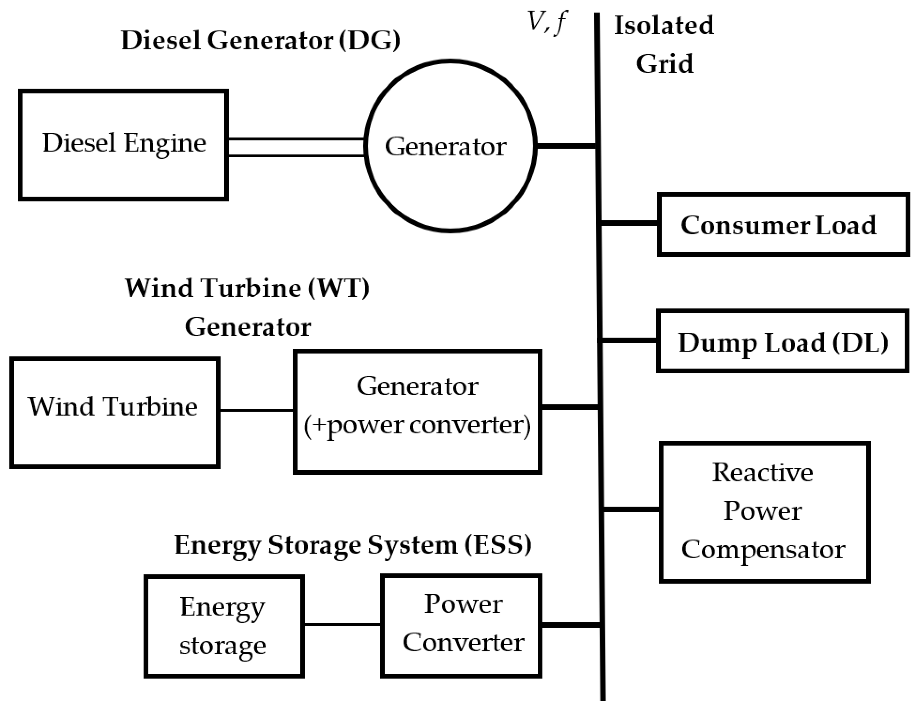
2. WDHS Configuration, Capacity and Location

The optimization of WDHS equipment (DG, WT, ESS) configuration and capacity, selecting WDHS location and operating modes lead to a decrease in fuel consumption. Generally, the choice of the best option is based on single objective optimization, which considerably limits the methods efficiency [25]. Single objective optimization methods include the iterative method [26], the graphical construction method [27], the linear programing [28], as well as the genetic algorithm (GA) [29] and particle swarm optimization (PSO) [30]. Specialized software is widely used [31], the most popular ones being Hybrid Optimization of Multiple Energy Resources (HOMER) and Hybrid Optimization by Genetic Algorithms (HOGA) [2].
Most software is acceptable only for pre-project rough evaluation due to a number of limitations: they use wind speed mean monthly values and there is no possibility of updating the program. This limits the development of new equipment control strategies [8]: it is preferable to use hourly measured or simulated electrical load and wind speed values.
The stochastic nature of WT power output and the necessity to solve multi-objective and nonlinear tasks brought about the use of artificial algorithms.
Diesel fuel consumption or CO2 emissions, as well as other technical and economic parameters applied to choose the optimal equipment configuration and capacity of the system elements, can be the objective function when solving the task of decreasing fuel consumption. They primarily include levelized cost of energy (LCOE), annual energy production (AEP), capital expenses (CAPEX), net present value (NPV) or net present cost (NPC), and payback period. Moreover, electric reliability, environmental friendliness and social criteria can be the objective function [32]. The formulas to specify these criteria are detailed in [33]. The key or characteristic criterion selection depends on the research goals.
If there are several criteria, multi-criteria decision-making methods should be used to choose the optimal system configuration. Almutairi et al. (2021) suggested a method based on hybrid stepwise weight assessment ratio analysis (SWARA) and weighted aggregated sum product assessment (WASPAS) [34]. This method allows the ranking of different system configuration options, setting its own weight coefficient for each assessment criterion.
Sensitivity analysis is carried out following the selection of optimal equipment configuration, in the course of which the impact of variable factors (diesel fuel or separate equipment cost) on the system core indicators is determined.

2.1. WDHS Optimal Sizing and Location

Al-falahi et al. (2017) reviewed the latest equipment size optimization methodologies of standalone hybrid RES-based power systems. The accuracy of consumer load profile and WT parameters (hub height and swept area) have considerable impact on optimization results. It was confirmed that newly developed hybrid algorithms (teaching–learning-based optimization algorithm (TLBO) and clonal selection, flower pollination algorithm (FPA/SA), and natural selection particle swarm optimization (NSPSO)) provide better quality results with less computational time compared with GA and PSO. Table 2 presents an overview (objective function, constraints and performance) of the hybrid optimization methods that can be applied to WDHS [35].
Hamanah et al. (2020) optimized hybrid WDHS equipment configuration with and without ESS by the lightning search algorithm (LSA) in Matlab. Annual cost is the objective function. ESS allows the cost of energy (COE) to be cut by 58% and the use of three times less powerful DG [9].
Ross et al. (2011) considered energy rating and power rating of ESS impact for various wind penetration rates. Wind penetration impact proved to be greater than that of ESS sizes. The mode of DG operation has an even greater effect on sizing of an ESS. If DG runs continuously the efficiency of using ESS increases together with increasing the wind penetration [45].
Nguyen-Hong et al. (2018) suggested a two-stage stochastic optimization framework when determining the optimal size of ESS in WDHS. In order to eliminate uncertain factors (wind speed and load growth rate), a scenarios reduction algorithm is used based on the maximum entropy principle and the K-means clustering approach [46].
Zhu et al. (2020) used an optimization method based on improved multi-objective grey wolf optimizer (IMOGWO) in order to optimize the size of an island hybrid energy microgrid. Selecting the optimal system size is a multi-objective problem including annualized cost of system (CACS) minimization and deficiency of power supply probability (DPSP). Optimization results confirm that IMOGWO provides better convergence compared to standard MOGWO and multi-objective particle swarm optimization (MOPSO) [25].
Size optimization of the hybrid systems with DG and WT can be performed using biography algorithms [47], improved bacterial foraging algorithm (BFA) [48], bi-objective ant colony optimization (BOACO) algorithm [49], firefly algorithm (FA) [50], grasshopper optimization algorithm (GOA) [51], cuckoo search (CS) algorithm [52], manta ray foraging optimizer (MRFO) [53], improved fruit fly optimization algorithm [54], bonobo optimizer (BO) [55], hybrid big bang–big crunch (HBB–BC) algorithm [56], differential evolution algorithm (DEA) [57], crow search algorithm (CSA) [58], advanced Pareto-front non-dominated sorting MOPSO (advanced-PFNDMOPSO) [59], whale optimization algorithm (WOA), water cycle algorithm (WCA), moth-flame optimizer (MFO) and hybrid particle swarm–gravitational search algorithm (PSOGSA) [60]. These methodologies can also be used when selecting the optimal WDHS location in the electrical network [59].
Jamiati et al. (2015) applied the group search optimization (GSO) algorithm to choose the optimal DG and WT location and size by the example of the IEEE 37 bus distribution network. The authors showed that simultaneous optimization of three objective function parameters provides better results than using one parameter [61].
Lan et al. (2017) suggested a two-stage method based on a non-linear auto-regressive model with exogenous inputs–back-propagation neural network (NARX-BPNN) and hybrid MOPSO to choose the optimal ESS size and location in WDHS. NARX-BPNN is used to predict WT energy production and load demand on the basis of historical data. NARX-BPNN allowed the ESS capacity to be reduced four times compared to the results obtained by static prediction methods. In order to increase algorithm converge speed, wind energy distribution is discretized by a three-point evaluation method and power–voltage (P–V) sensitivity analysis is applied. By the example of an IEEE 30 bus system, it was shown that the proposed hybrid MOPSO algorithm enables the optimal location of ESS to be determined, resulting in a reduction in total operational costs by 15% on average, as well as greenhouse gas emissions by 3%, compared to the design variant where ESS are installed on the same bus as WT [10].
Most research dealing with WDHS size optimization does not consider the possibility of a demand response or load shifting control. At the same time, García-Vera et al. (2020) proved that demand response control enables the reduction of ESS optimal size, improving technical, economic and environmental indices [62]. It is possible to reach a LCOE reduction of more than 20%, while the investments in ESS of about 10% [63].
Lavrik et al. (2021) suggested a multi-objective optimization method of stand-alone WDHS size, considering the possibility of load shifting control. The optimization was carried out by a classical Gauss–Seidel iteration method according to the minimal NPV criterion considering a limited payback period. As a result, DG service life was increased two times, while LCOE was reduced by 40%. Load shifting control enables the load share not covered by RES to be lowered by 2.1%, as well as to decrease NPV and payback period, whereas CO2 emissions go up due to ESS reduction [8].
Xia et al. (2021) suggested a price-based demand response model and a method of selecting optimal hybrid microgrid configuration on the basis of real-time electricity price. The optimization is carried out on two levels: the source and the load. At the source side, the necessary number of DG and ESS capacity is determined according to the set number of WT. The lowest comprehensive cost of distributed power planning is used as an objective function. At the load side, according to the demand-price elasticity matrix model, the minimum absolute value of the difference between the power of the electric load and the power generated by renewable energy at 24 moments a day is used as the objective function to calculate the real-time electricity price and derive the electric load after demand response. The model allows the decrease in the number and power of DG and ESS, and the reduction in total economic costs and customer electricity costs by increasing the RES penetration rate [64].
Systems with a high WT energy penetration rate are known to have poor reliability. In case of the absence of wind or an emergency, a vast amount of power output is almost immediately lost which leads to the system loss of stability. That is why national operators strongly require that the network WT has a spinning reserve by conventional energy sources which are able to compensate the WT generation change, maintaining the frequency within the system. In this case, the WT penetration rate is limited by the necessary spinning reserve available.
In order to assess the WT maximum wind power penetration, voltage and frequency values are estimated in the system in steady-state and transition modes in the event of emergency situations. The values obtained are compared to the admissible limit values regulated by networking standards. Chang et al. (2016) put forward a methodology of determining the maximum WT penetration in a stand-alone power supply system considering spinning reserve. Herewith, it is necessary to consider WT effective load-carrying capability (ELCC). Unlike traditional unit scheduling criteria, according to which WT cannot be scheduled, the authors suggest considering a fraction of WT total installed power as part of SR power. The suggested approach allows annual diesel fuel costs to be cut by 7.47%. In order to increase the WT penetration rate, they suggest increasing the number of online DGs [65].
Elistratov et al. (2019) put a forward parameter validation methodology of locating and estimating WDHS efficiency in order to enhance electric power supply reliability of remote and off-grid communities and settlements and to reduce diesel fuel costs. The methodology envisages a multi-level system-based assessment of energy resources potential, the current electric power supply analysis, climatic information, as well as WDHS equipment parameters and operating mode optimization. Under the methodology, harsh climatic conditions of operating WDHS in the Arctic are considered by an additional coefficient: losses due to icing, snow loads, air density and humidity changes and extremely low temperatures. The calculation results are presented in the geoinformation system [66].

2.2. Project Efficiency Calculations

Al-Sharafi et al. (2016) suggested a double-step performance assessment tool for hybrid systems. The total efficiency index takes into account economic effectiveness using COE, energy excess percentage (EXC), operating life cycle (OLC), as well as ecological effects by coefficients of renewable contribution (RC), renewable source availability (RSA) and environmental impact (EI). Every coefficient is assigned its weights, with their values depending on the project goals [67].
Connors et al. (1990) suggested a WDHS simulation with a battery ESS (BESS) for a village-scale system taking into account generalized characterization of the local wind regime and electrical load demands (including prioritization). At the first stage, an hour-by-hour simulation of one month of operation is performed; following this, the data obtained are transferred to the efficiency estimate model. The proposed model allows the relative cost of electricity and socio-economic impact to be estimated [68].
Himri et al. (2008) provide a WDHS technical and economic assessment in the south-west of Algeria. HOMER software is used to estimate the power plant energy production, its life-cycle costs and greenhouse gas emissions reduction. The wind speed and the fuel cost at which building WDHS becomes profitable are established [69].
Bhattarai et al. (2016) used HOMER software to select an optimal source of electric power supply for an off-grid community of Brochet, located in Northern Manitoba (Canada). Compared to the existing DG set, building WDHS allows the reduction in cost of energy by 30% and carbon dioxide emissions by 18%, while maintaining the whole system reliability at the current level [70].
Shezan et al. (2015) carried out the analysis of using a stand-alone WDHS with an ESS in Cameron Highlands hotels in Malaysia. From the point of view of providing the consumer with the necessary electric energy [kWh/day] at the necessary peak power, the optimal WDHS equipment configuration was determined with the help of HOMER software providing the lowest cost of energy [71].
Giannoulis et al. (2011) estimated the economic impact of building a stand-alone WDHS on the Isle of Lesbos in Greece using HOMER software. They present a sensitivity analysis of diesel fuel price, hub height, the number of WT, penalties for CO2 emissions, wind energy operating reserve at the optimal level of WT energy penetration [72].

2.3. Reliability and Stability Estimate

Liu et al. (2006) put forward an analytical approach to estimate the reliability of stand-alone WDHS with BESS. This approach is based on a discrete speed frame analysis of the Weibull wind speed distribution and considers power cutoff caused by elements’ failure and wind speed fluctuation. The calculations resulted in reliability indices: loss of load probability (LOLP) and expected energy not supplied (EENS) [73].
Tremyasov et al. (2017) suggested the dynamic fault tree method with Markov models for representing dynamic operators in order to estimate stand-alone WDHS reliability. The method takes into account WDHS failures in the model which are caused by weather conditions. The events’ dependence on the sequence and failure events priorities are considered using dynamic operators. WDHS reliability is calculated in order to choose its optimal structure. The reliability is determined by the forced outage rate value and the stream parameter of fault [74].

3. Main Equipment Improvement

The main WDHS energy units are DG and WT generator (Figure 2).
DG comprises a diesel engine driving a synchronous machine rotor. The internal combustion engine (ICE) converts fuel energy into shaft rotation mechanical energy by fuel combustion in the cylinders. In order to change the engine power (speed), a speed controller is used, affecting the consumption of fuel entering the cylinders. Mechanical rotational energy is converted into electrical energy by a synchronous generator which also provides a sinewave of frequency f and amplitude V. Generator output voltage amplitude is controlled by an automatic voltage controller regulating reactive power.
WT generator comprises WT converting wind kinetic energy into electric generator rotor spinning mechanical energy in which it is converted in electrical energy. Two types of WT are most widespread: horizontal axis wind turbine (HAWT) and vertical axis wind turbine (VAWT). The conceptual difference of these two construction types is the necessity to point horizontal devices with the wind. Moreover, HAWT require a high tower, as the height layout provides a more intensive wind flow effect on the rotor. Four types of generators are singled out: (1) cage rotor inductor generator; (2) wound rotor induction generator (WRIG) with variable rotor resistance; (3) doubly fed induction generator (DFIG); and (4) full converter. WT generator can be connected directly to the grid or through power converter depending on the generator type.
WDHS can also comprise an ESS, a ballast (or dump) load, a reactive power compensating installation and a control system. BESS connected through a semiconductor converter are most often used in WDHS [2]. Other types of ESS can also be used. Ballast load is necessary to discharge energy surplus produced by WT at small loads if all ESS are fully charged. It represents a block of resistors connected via power switches or semiconductor converters, and functions as an active consumer.
WDHS are subdivided into three groups depending on the rate of organic fuel replacement [76,77]. These groups differ according to both installed power of WDHS equipment and its operating mode (Table 3).
The higher the wind energy utilization rate, the lower the organic fuel consumption and the more environmentally friendly the WDHS operation. Thus, in order to decrease diesel fuel consumption, it is necessary to increase WT penetration.
Depending on WDHS equipment configuration and operating modes and WT penetration, different WDHS structural design variants are possible [35,79,80] (Figure 3). The most popular is the scheme where the sources are connected directly to the load AC bus without intermediate power conversion (Figure 3a). This scheme provides the highest efficiency. However, it is necessary to take special measures to maintain the joint operation of several sources with various capacity and to distribute load among them.
In Figure 3a, DG operates at fixed output shaft speed at any load which is necessary to obtain the 50 (or 60) Hz frequency. WT can operate at variable shaft speed; for this purpose, its output is connected to the AC bus via a rectifier (R) and an inverter (I). In no-wind conditions and hurricanes, WT cuts off and DG take on the whole load. WT power should not exceed that of DG by more than 20%.
The block diagrams in Figure 3b,c are applicable to zones with high wind potential when WT can function as the primary energy source. Herewith, DG power can be considerably lower than that of WT, while a greater capacity ESS is connected for energy storage. In Figure 3b, WT and DG are interconnected on the AC bus, while ESS charge–discharge is carried out via a bidirectional converter (BC) connected to the rectifier output. In Figure 3c, ESS is charged through BC from the DC bus during joint or isolated DG and WT operation. ESS gives up energy into load via BC and inverter if necessary. DG and WT can operate in variable shaft speed modes and, consequently, with variable power output. Such a mode enables DG to reduce power output in order to decrease fuel consumption. WT has the opportunity of operating in the mode of using the maximum wind energy [81].
Sebastián (2021) presented a review of dynamic models for WDHS-based isolated microgrids and classified them according to the equipment type and operating modes [75].
Chernov et al. (2018) presented an assessment of the impact of share of the WT generator capacity in the WDHS installed capacity, as well as the consumer composition impact on the amount of replacement of the DG energy output. They proved that when WT is integrated into an operating DPS, a considerable DG load decrease is observed resulting in the DG operating with increased diesel fuel consumption [82].
Wind speed and consumer load demand change result in DG operation in transition dynamic modes at small loads or beyond the prescribed environmental conditions. A continuous long-term DG operation at small loads results in residue of fuel combustion condensation on engine cylinder walls, which, in turn, leads to friction intensification, decreases efficiency and increases fuel consumption over time (Figure 4). Moreover, the DG load decrease from 75 to 25% increases HC, CO and NOx specific emissions by two to three times. One of the ways to solve this problem is the engine running at higher rpm until it reaches operational temperature. The impact of WT penetration and environmental conditions (temperature, humidity, cold and aggressive environment) on DG characteristics is studied in [77], based on analyzing DG operating experience and recorded cases of DG failure.

3.1. Variable Speed DG

Fuel saving in WDHS with high wind penetration rate is limited as (1) DG load decrease does not result in proportional fuel saving, and (2) it is not recommended to run diesel engines with a load below 40–60% of their rated load as it negatively impacts diesel service life (excessive oil consumption, etc.) [13].
Fixed speed generators are conventionally used in DG. A standard solution to reach high WT penetration is to cut off DG in minimum load periods. However, in this case, an expensive ESS is needed which makes no economic sense to isolated low demand consumers.
Low load operation is the simplest way to improve DG flexibility which does not require making any engineering changes in the engine structure. For this purpose, low load operating limits in the engine control unit are removed. Using low load DG allows the decrease in fuel consumption of WDHS with high wind penetration rate by 6.3%, compared to running fixed speed generators, as well as the decrease in the ESS installed capacity. However, frequent purging is required for the engine normal operation and its service life maintenance in this operating mode [84]. Diesel engines operating at low loads must be brought up to high loads (at least 40–50% of full power) regularly to avoid operational problems. Increased engine loads raise the pressure and temperature, scrap the liner lacquering, and burn the soot deposits and unburned coal [77].
A common approach to improve WDHS efficiency is to use variable speed DG. WT penetration increase and diesel fuel consumption decrease are provided by diesel engine speed reduction at small loads without the use of ESS.
The DG control system reduces the generator speed to its optimal value at partial loading (Figure 5), the fuel amount in the cylinder increases, while the engine thermal inertia and combustion efficiency are preserved [14].
This technology allows the decrease in fuel consumption (up to 40%), greenhouse gases emission and operating costs compared to a conventional DG [12]. By reducing engine idle time in low load mode, the engine service life increases. Figure 6 shows a comparison of the variable and fixed speed DG efficiency.
If WDHS comprises one DG, this must be variable speed DG. If WDHS includes several DGs, variable speed DG must be the first to start [13].
Variable speed operating mode can be realized by both mechanical systems (gear unit), and electrical ones (power converter). Electrical systems provide the best performance characteristics at the least costs [14].
Mobarra et al. (2022) compared the efficiency and characteristics of variable speed DG structures: diesel-driven DFIG, diesel-driven WRIG, diesel-driven permanent magnet synchronous generator (PMSG), super-capacitor diesel generator (SCDG), rotating-stator mode for diesel generator (RSDG) and continuously variable transmission (CVT). The analysis of the characteristics of the described structures is given from the point of view of energy saving, greenhouse gases emissions, total harmonic distortion (THD) reduction. WRIG is marked as having the most efficient technology to be used as part of hybrid RES system due to its low dynamic response [12].
Kocheganov et al. (2019) suggested an energy efficient variable speed WDHS structure with two electrogeneration channels. Variable-voltage generators, uncontrolled rectifiers and stabilizing converters are mounted at the DG and WT output. The sources are interconnected on a DC stabilized voltage bus. An automatic control system provides the maximum power take off from the wind wheel at each wind current speed value. If the load power exceeds WT power, the control system adjusts the power intake from the ICE. The ICE is equipped with a speed controller providing the optimal rpm depending on the load power intake [86].
Manwell et al. (1992) suggested integrating DG and WT energy channels by a common AC/DC/AC inverter (Figure 7) [13]. Variable speed and voltage generator power output is converted by the inverter into fixed frequency and voltage power. Control system adjusts engine controller settings in such a way that the engine speed changes according to the required power. WT can also have variable speed, but it uses the same inverter as the DG.
Apart from the WDHS fuel consumption decrease (up to 37% compared to the fixed speed one), implementing variable speed DG allows the number of start/stop cycles to be reduced.
Hamilton et al. (2022) suggested a modified hybrid DG (Figure 8) which can operate in two modes depending on the load: with variable speed (up to 30% loading) and fixed speed (over 30%). In the variable speed mode generator, energy enters the rectifier, and its power is 1/3 of the generator power. Mode switching happens automatically. In order to provide smoothness of the generator transient response during mode switching and due to the system inertia decreasing in variable speed mode, ESS are to be connected to the DC bus [14].
Moreover, the system structure provides the possibility of integrating two energy channels (DG and renewable source) on the common DC bus prior to the inverter. This solution increases the inverter loading, thus boosting its efficiency coefficient. The calculation results show that hybrid DG penetration allows WDHS fuel consumption to decrease by 42% (for WDHS without ESS) and by 10.9% (with ESS), as compared to the fixed speed DG.

3.2. WT

WT energy production efficiency influences the overall WDHS performance. The more energy WT produces within a year, the shorter the DG running time, the number of its starting cycles and, consequently, the lower the diesel fuel consumption.
Wind speed primarily influences WT efficiency. Thus, the simplest way to increase WT energy production is to set the turbine in regions with wind speed high annual average values. The higher the turbine setting (tower), the higher the wind speed and energy production. However, the height of the turbine setting is limited by structural and other restrictions, and consequently, additional methods of efficiency improvement are necessary.
Traditionally, HAWT are widely used due to their efficiency. The VAWT advantage is that there is no need to position the turbine with the wind. Modern VAWT are able to operate efficiently even at low wind speed.
Most WT are fixed speed wind turbines (FSWT), whereas variable-speed wind turbines (VSWT) have a number of advantages: energy capture increase, smoothness of rotation, transmission load decrease, and no need to employ a flow control technique. VSWT structure enables WT to produce the maximum power if the rotor is spinning at an optimum speed with the corresponding wind speed. Optimum rotor speed depends on rotor-generator characteristics and is maintained by the MPPT controller.

3.2.1. HAWT

  • Turbine structure.
Wind turbines theoretical efficiency cannot exceed 59.3%, which corresponds to power factor Cp = 0.593. Real operating efficiency will always be lower than the theoretical one due to rotary strengths, such as wake rotation, turbulence caused by drag or vortex shedding (tip losses), which reduce the maximum efficiency.
For loss of efficiency enhancement, the following is required: to avoid tip speed ratios increasing wake rotation; to select aerofoil sections with high lift to drag ratio; and to use special tip geometries.
Depending on the rotor design, modern three-blade HAWT peak efficiency can reach 50%, while VAWT efficiency can reach 40% [87].
  • Blades.
HAWT efficiency depends heavily on blade profiles and design. Schubel et al. (2012) studied WT turbine structures with a horizontal axis of rotation having various blade numbers and profiles, aerofoil section and optimum angle. As a result, they singled out structural versions having a theoretical maximum efficiency and practical efficiency [87].
Turbines with a high tip speed ratio (TSR) (λ ≥ 10, where λ is the tangential speed of the tip of a blade to wind speed ratio) have greater efficiency. On the other hand, they have several drawbacks, such as excessive noise and aerodynamic and centrifugal loads due to which the risk of blade breakage appears. Consequently, for high tip speed turbines, it is necessary to decrease the chord width, making narrow-profile blades. At lower wind speed, such blades develop a minimum torque, so WT have a higher cut in speed and difficulty self-starting. The optimal value is λ = 9–10 for two blades and λ = 6–9 for three blades.
Optimal blade and chord length are determined by the blade element momentum (BEM) method and depend on the TSR and the number of blades (Figure 9).
A turbine blade consists of three areas: root, mid span and tip. The blade structure should provide the maximum aerodynamic lift. To achieve this an aerofoil section should have a lift to drag ratio of over 30. The thinner an aerofoil section is, the less its drag; therefore, the turbine efficiency is higher.
Every blade area should have its own aerofoil: it should be thick at the foot (thickness to chord ratio > 27), in order to endure high stresses, while closer to the tip the blade thickness decreases (thickness to chord ratio of 21–15) in order to reduce the drag.
The indicated values are design values and hold true when the turbine operates at nominal wind speed. However, due to the wind speed changeability, turbines practically always operate at the wind speed which is lower or higher than the nominal one. At the same time, turbine performance should remain efficient. In order to maintain efficiency at a wind speed different from the nominal one, pitching is used, which provides the required aerofoil section lift. The blade turns through the hub, changing the blade angle and angle of incidence. It is possible to use both collective pitch, at which all the blades turn simultaneously through an identical angle, and individual pitch [87].
In order to improve the turbine efficiency, the blade structure can be updated by adding special aerodynamic elements which separate the wind flow, thus increasing the lift and reducing the drag. Both active and passive flow control techniques are used. The active ones require additional energy source to control the flow, whereas the passive techniques do not require this and so appear more economically feasible. Using active techniques is practical only for high-power large-scale WT (MW). Rehman et al. (2018) researched different methods of improving HAWT blade efficiency: applying passive and active techniques of increasing the turbine power output, decreasing cut-in-speed, and using advanced materials [88]. Singh et al. (2012) proved that blade structure modification can decrease WT cut-in-speed. Pitch angle change allowed the reduction in minimum and medium two-blade turbine cut-in-speed to 2.34 and 3.24 m/s, respectively [89].
Fernández-Gámiz et al. (2017) researched the impact of two passive flow control devices, vortex generator and gurney flap, on 5 MW turbine performance efficiency. With the help of the blade element momentum (BEM) method, results were obtained confirming that the blades with passive flow control devices increase the turbine power output by 10.4 and 3.5% depending on the wind speed average speed. Herewith, larger values of power output increment are observed at lower wind speed (5 m/s) [90].
Smart blades use two approaches: aerodynamic control surfaces or smart actuator materials, enabling the modification of the blade configuration depending on the wind parameters. Aileron style flaps, microtabs, camber control, active twist and boundary layer control can be used to control surface aerodynamics. Barlas et al. (2010) presented a detailed review of publications dedicated to this problem which confirm the efficiency of using smart rotor control [91].
A great variety of turbine blades structures results from a wide WT application area. Each blade configuration corresponds to its location and range of wind speed. Vučina et al. (2016) presented a computational framework for turbine blade configuration optimization depending on wind distribution on-site. Annual energy production, NPV or internal-rate-of-return (IRR) can be used as the objective function [92]. Apart from single objective optimization, two-objective, three-objective, and four-objective optimizations can be used, for example multi-objective differential evolution optimization, suggested by Wang et al. (2017). It was proven that increasing the number of objective functions has a positive effect on distribution, convergence and convergence efficiency of the algorithm [93].
When operating WT in the Arctic, the problem of blade icing appears, resulting in the turbine power factor decreasing to 30%. Both passive and active anti-icing systems, including special blade facing materials, blackening and heating are used as anti-icing measures. Elistratov et al. (2021) suggested using a pitch and tip-to-speed ratio control to reduce the effect of icing. The suggested turbine control circuit can potentially reduce the effect of icing by 2–5%; however, installing such a system is practical for WT with a capacity of more than 300 kW [22].
  • Turbine.
Apart from re-designing WT blades configuration, the modernization of a turbine structure as a whole is a separate avenue of research, using special augmentors steering large wind currents to the turbine blades.
Han et al. (2015) suggested a one-stage HAWT structure with a shroud and lobed ejector for low wind speed regions. The calculation results in the CFX complex showed that wind energy utilization efficiency increased by 66–73% at 2 to 6 m/s wind speed. At the same time, the turbine power output increased by 240% [94].
Allaei et al. (2014) presented a HAWT structural design with increased velocity (Invelox), which allows drawbacks of the traditional HAWT to be avoided. The Venturi tube is used for air current collection, acceleration and steering it to the turbine blades [95]. The wind collector collects wind energy of any direction. The collected airflow goes through the funnel and after being speed up, it enters the turbine located in the Venturi tube (Figure 10). Electric power output increases by 80–560% compared to the conventional HAWT. Such a structure is able to produce energy even at a speed of as low as 0.45 m/s.
Research results of Sotoudeh et al. (2019) showed that with the assembly height increase from 10 up to 40 m, the power output increases by 87.5%. An improved design of two-storey Invelox turbine was suggested, with an additional funnel on its top. This design allowed to increase power output by 44% [97]. Ding et al. (2020) suggested improving and re-designing the Invelox structure to provide high efficiency at any wind speed direction. A straight-through layout with a windshield was suggested for this purpose [96].
Adeyeye et al. (2021) presented optimization results of a new type of turbine: Ferris wheel turbine (FWT). It comprises a rim, a wire, a hub, a blade, a generator, a tower and a turbine foundation. The blades are mounted on wire spokes, creating a Ferris wheel, and rotate around the central shaft. This design makes it possible for the blades to self-pitch and self-twist in order to keep the blades’ leading edges at an optimal incidence angle to gain the maximum lift. It was shown that as the rim diameter and the number of spokes (blades) increase, the turbine efficiency increases [98].
  • Generator.
Variable speed PMSG are connected to the network via a semiconductor converter and, therefore, possess no drawbacks which are inherent to fixed speed asynchronous induction generators. In isolated networks they provide an active and reactive power flow control without any special devices, improving the power quality and voltage stability [16].
The generators which are widely used as WT are DFIG. They are represented by a slip ring induction motor or wound rotor induction machine. The generator rotor is connected to the network via an AC/DC/AC bidirectional converter which includes rotor side converter (RSC) and grid-side converter (GSC), connected through a DC-link. The converters control the rotor speed and the output power. The generator stator is directly connected to the network. The DFIG structure allows the power of fixed voltage and frequency to be generated, regardless of changing rotor speed. One of the main DFIG advantages is the possibility of an active and reactive power independent control, allowing the power factor to be controlled.
Wu et al. (2016) presented a comparison of different RSC DFIG-based WT control strategies. The simulation results in PSCAD showed that the direct torque control (DTC) of the RSC converter provides electromagnetic torque direct control and thus provides a better dynamic response in the turbine MPPT operating mode. GSC operated in voltage-oriented control (VOC) mode, maintaining DC on the bus [99]. Chhipa et al. (2022) suggested using RSC and GSC vector control. The proposed MPPT controller provides efficient WT operation at wind speed fluctuations [11].
Puchalapalli et al. (2021) put forward synchronizing control DFIG-based WT as part of island WDHS. DFIG and WT are connected via a static transfer switch. An additional frequency loop is integrated into the RSC control circuit to reduce power fluctuations and to ensure smooth shifting. WT peak wind power generation is the purpose of the RSC algorithm. RSC maintains nominal voltage even as the rotor speed decreases to its minimum values. The task of the load side converter (GSC analogue) control algorithm is maintaining the DG operating mode within the range of optimal fuel consumption even at sharp load decrease and at unbalanced loads [100].
Lukasievicz et al. (2018) put forward a management approach using additional controllers for isolated hybrid WDHS with WT DFIG. DG is used to control DC-link voltage. Two extra controllers were added to DG and DC dump load. The suggested approach does not require a BESS and an ultra-condenser to control DC-link voltage. WT operates in V–f control mode, while DG operates in PQ control mode. A strong impact of wind turbine rpm frequency on DC-link is mitigated by a low-pass filter introduced into the wind turbine speed control loop [101].
WT can be equipped with two parallel generators connected with the rotor shaft. Depending on the wind speed, a higher power generator (at high wind speed) or lower power generator (at low wind speed) are connected to the rotor shaft. Such a scheme provides a dual-speed operation mode [102].
  • Layout.
For higher power output, it is necessary to combine several WT into a single cluster. Herewith, it is necessary to consider the wake effect, that is, wind speed reduction behind the rotor. Thus, the problem of optimal WT group layout arises. Sultana et al. (2022) presented a model of wind turbine layout based on PSO and wake effect minimization [103].

3.2.2. VAWT

  • Structure.
Studying aerodynamic characteristics is also essential for VAWT. H-rotor Darrieus VAWT are based on the principle of lift and usually demonstrate higher efficiency compared to drag-type Savonius VAWT. However, open-ended blades produce tip loss effects, lowering the power output. Wingtip devices, such as winglets and endplates are used in the airfoil section to increase its efficiency. Ung et al. (2022) compared different types of wingtip devices and estimated their influence on the Cp power factor. Symmetric V endplate showed the best effect [104].
  • Layout.
Unlike HAWT, small-size VAWT can be laid out at a small distance from each other, providing high power output performance per occupied space unit. This is particularly true for VAWT with counter-rotating paired rotors. Vergaerde et al. (2019) experimentally showed that when two-bladed H-type Darrieus VAWT are installed next to each other in a plane normal to a uniform inflow, the power is increased by 16% compared to the output by two separate VAWT [105]. The closer the VAWT rotors are located, the stronger the effect is, which can reach nearly 70% at the rotor diameter to the distance between the rotors ratio d/D = 1.6 [106].

3.3. Economy Mode Setting Device

Dar’enkov et al. (2020) suggested a WDHS intelligent control system based on an economy mode setting device (EMSD) regulating ICE fuel supply [15]. The EMSD flowchart is shown in Figure 11.
EMSD is an adaptive controller consisting of four basic elements: the main controller, teaching control, content-addressable memory unit and non-volatile memory connected by one common data bus. EMSD optimizes the engine shaft speed, regulating fuel supply to the ICE depending on the internal and external operating environment. The control signal is generated by the content-addressable memory unit which is an artificial neural network program simulation. Optimum ICE shaft speed is determined in real time.
The principle of EMSD operation is as follows. The sensors record the following parameters: DG power (Pω), ICE fuel consumption (ge) and ICE shaft speed (ω). These parameters are transferred to the learning controller where they are compared with similar parameters available in the data memory block. If the parameters of the current mode match one of the modes’ parameters stored in the data memory unit, the learning controller reads out the information about the position of the fuel pump rail (value h) and transmits it to the management controller. The management controller forms a control signal in the ICE fuel supply system. This results in the fuel pump rail moving in the right direction by the required number of steps. If the learning controller input data do not match any mode stored in the data memory block, the learning controller performs several learning cycles of the memory block. Following the learning process, a new optimal position of the fuel pump rail is formed, which is transmitted to the management controller. The new mode parameters are additionally formed by input (Pω, ge and ω) and output (h) parameters which are stored in the data memory block.
The WDHS intelligent control system algorithm was designed and tested using the Simulink model. Specific and absolute fuel consumption change dependencies on load power for two 4 kW DGs were obtained: a fixed speed DG and a variable speed DG with EMSD (Figure 12). Using EMSD in the low-load mode allows fuel consumption to be decreased by almost 30%. The error of determining optimum engine speed using EMSD prototype does not exceed 15%.

3.4. Energy Storage System

ESS is one of the basic elements of any hybrid electric power station. An ESS is necessary to maintain an active and reactive power balance at any specific time, providing stability of voltage and frequency values in the system. Moreover, ESS allows an increase in the fraction of renewable energy use and a reduction in the number of DG starts/stops and the total fuel consumption.
The simplest and most widespread type of ESS for short-term energy storage is BESS [2]. However, these systems have certain limitations, such as low charge/discharge rate, limited capacity, necessity of recurring maintenance. Apart from batteries, ESS based on ultra-condensers (UC), superconductive magnetic energy storage (SMES), flywheels, compressed air, hydrogen and flow redox battery can be used.
Shaahid (2013) estimated ESS capacity and RES penetration impact on WDHS technical and economic performance. The WDHS storage capacity increase from 0 to 6 h of autonomous load supply allows environmental emissions and annual fuel consumption to decrease by 12%, but along with this, the system COE goes up by 22%. Compared to solely DG operation, WDHS with ESS fuel saving is 28%. A further increase in ESS capacity does not bring about the desirable effect due to the lack of energy produced by one WT. Increasing the WT number and wind penetration almost linearly influences the reduction in the number of hours of DG operation and fuel consumption: a wind penetration increase from 0 to 65% decreases fuel consumption by 51% [107].
Li et al. (2020) presented a technical and economic assessment of hybrid WDHS with three types of ESS: lead-acid (LA), zinc-bromine (ZB) flow and lithium-ion (LI). Using ESS for WDHS operating at low annual average wind speed allows COE and annual fuel consumption to decrease by almost 56 and 72%, respectively. From the point of view of COE, the optimum alternative at low wind speeds is using ZB flow battery, whereas COE for LA and LI is 30 and 36% higher, respectively. With regard to fuel consumption reduction, the optimum alternative is WDHS with LI and LA BESS, with 5% fuel saving compared to ZB flow ESS [18].
Hussain et al. (2020) compared the efficiency of using various types of ESS combinations as part of WDHS: BESS, SMES and UC [108]. They confirmed that BESS and SMES combinations provide the best dynamic response.
Monroy-Morales et al. (2022) introduced WDHS with flywheel ESS (FESS) and dump load, which are used for WT energy surplus storage and consumption. FESS is connected through two three-phase full-bridge converters in a back-to-back configuration: the grid-side converter and the machine-side converter. With a surplus of WT energy, diesel engine cuts off the generator by friction clutch, while an energy surplus is accumulated in FESS if its state of charge (SOC) is less than 95%. If the SOC exceeds 95%, FESS is no longer capable of storing energy and energy surplus is consumed by dump load. At low wind speeds, the accumulated FESS energy is consumed. When FESS is discharged to 45%, the DG is started. The simulation results confirm that the proposed system is able to maintain frequency and voltage in the system within the standard range and limits at load and wind speed change [109].
Compressed air energy storage (CAES) operates under the compression–decompression cycle principle providing large WT penetration and an optimum DG operating mode. With WT output surplus, air is compressed by an M compressor and accumulated in the reservoir (Figure 13). At low wind speed, the compressed air is injected into the diesel engine which can operate in three modes: supercharged, hybrid and pneumatic, increasing power and decreasing fuel consumption two-fold [17]. Ibrahim et al. (2012) showed that WDHS with CAES reduces annual fuel consumption by 27% compared to using a DG only system, while the savings from a WDHS without CAES are only 15%. At the same time, the WDHS without CAES allows a 13% reduction of annual maintenance and operation costs, while with CAES, this rate increases to 51% [110]. Direct injection of compressed air into the diesel engine under 3–4 bar pressure and low temperature allows the optimum air/fuel ratio to be reach [111].
According to Sedighnejad et al. (2011), CAES systems of various pressure Matlab simulation results proved that 27 bars is the optimum pressure [112]. A further pressure increase leads to the loss of efficiency of the compressor. Satisfactory efficiency level can be reached using several compression stages together with a high-efficiency cooler–heat exchanger for compressed air cooling and preheating. However, this will require a more complex system design and greater costs for its implementation.
Martinez et al. (2019) proved that fuel consumption goes down with the compressor’s compression stages, as well as its efficiency (polytropic efficiency) going up. It also depends on the reservoir capacity for hydrogen storage: the bigger the reservoir (the less the hydrogen pressure), the less the fuel consumption. Overall system performance depends on the size of installation and the WT penetration ratio. CAES introduction allows fuel consumption to decrease by 12% at 40% WT penetration, and by 27% at 80% WT penetration [17]. Benchaabane et al. (2019) developed a computer model to carry out a financial and environmental analysis, as well as WDHS with CAES risk analysis [113].
Saad et al. (2017) suggested WDHS with adiabatic air compression and storage at constant pressure (ACP-WDCAS), combining CAES and hydropneumatic energy storage technologies. Such a solution enables the DG to overcharge with direct admission of compressed air into the engine. It was shown that fuel consumption goes up with the increase in engine inlet pressure and it is possible to determine the pressure at which the consumption will be optimal. The optimum pressure value increases with the increase in engine load. Intake air temperature is also important. High air temperature is preferable at low values of DG load, whereas at high load, fuel consumption decreases proportionally with the decrease in intake air temperature. ACP-WDCAS provides fuel saving compared to conventional CAES due to optimum engine operation [111].
The energy surplus produced by WT can be used for hydrogen generation in electrolysis plants. Long-term energy storage is an advantage of the hydrogen storage unit. At peak hours and low wind speeds, hydrogen is used for electric energy generation by the internal combustion hydrogen generator or hydrogen proton exchange membrane and phosphoric acid fuel cells (PEMFC, PAFC) [114]. Flynn et al. (2007) proved that the hydrogen storage unit allows diesel fuel consumption to decrease by 2.5%, expanding the WT penetration ratio by 1.3%. A nearly two-fold increase in hydrogen tank capacity has no considerable impact on fuel saving (which is less than 1%) [16].
Segurado et al. (2011) suggested using WDHS with pumped hydro storage to supply the population of S. Vicente Island with electricity and fresh water. DG is used as the primary energy source. Part of the energy produced by WT is used to distill water, which is further on supplied to the population, as well as to energize pumps of pumped hydro storage, dispensing untapped water from the lower reservoir into the upper one. The remaining WT energy fraction is supplied to consumers in the form of electrical energy. The hydroelectric power plant is used to cover the peak load. Simulating various system operation modes at different WT penetration ratios in H2RES showed that pumped hydro storage operation is efficient at a high wind penetration rate [115].
These systems became widespread in isolated island systems. Most of the research findings show that such systems’ efficiency largely depends on the wind potential. Katsaprakakis et al. (2014) suggested solving the problem of low efficiency at low wind speeds by using offshore wind farms’ energy and large capacity reservoirs. The sea is used as a lower reservoir while sea water is used as an energy carrier. The lower and upper reservoirs are connected by double penstocks, their cross-section diameter allowing the use of the pipes for simultaneous water fall and pumping: one pipe is used only for water fall, while the second one is used for pumping. Compared to using only one penstock, this method allowed the annual wind energy ratio to increase by 9.3%. Pumped hydro storage enabled DG to decrease energy generation by 50%, providing a 40% fuel consumption decrease [19]. However, it should be noted that DG will operate with excessive fuel consumption due to the load decrease and the system’s overall efficiency going down. Besides, such a system construction would be rather expensive.
Asif et al. (2013) presented diesel fuel consumption calculations for various operating modes of WDHS with pumped hydro storage, BESS and damping load. The maximum daily fuel consumption economy (up to 20%) is achieved if DG cuts off whenever the system load goes below 30% of the DG nominal power. However, this mode results in frequent DG switching, which negatively impacts the system resource and lifetime, while frequency deviations in the system reach 7 Hz. If variable speed diesel is used, the DG can operate at the load beyond 30%. In this mode, frequency deviations are practically absent and fuel saving is 13%. Decreasing the number of switches is possible without the speed control if the DG keeps operating in the current mode (present state) for at least 10 min after the recent switchover. Frequency drops in this state will reach 10 Hz, while the economy will only be 9.2% [116].
Stiel et al. (2012) estimated the potential of using vanadium redox battery (VRB) in a large remote WDHS by HOMER Micropower Optimization Model [20]. VRB has considerable advantages over other electrochemical storage types such as a long-term service, lower capital and operating costs and almost unlimited capacity due to the possibility of autonomous power and capacity extension [117]. The calculation results show that a plant with a VRB having power equal to the system peak load is a more feasible solution compared to installing an extra DG. With the VRB installed, the annual fuel consumption decreases 4.4 times in comparison with WDHS without an ESS [20].
In order to reduce WDHS frequency deviations, SMES can be used. SMES is an energy storage based on superconducting coil made of niobium titanium (NbTi) or magnesium diboride (MgB2). It has low power losses, a high energy density, a quick response time and a high charge–discharge rate. Thoker et al. (2021) suggested using a sliding mode controller based on neural network adaptive radial basis function in order to control the SMES converter. Disturbance simulation results in Matlab confirmed the proposed control circuit efficiency, lowering the values of frequency deviations and setting time [118].
Mishra et al. (2022) suggested using a combination of unified power flow controller (UPFC) and SMES in an isolated microgrid with WDHS to mitigate low-frequency power fluctuations and for system load frequency control in transient modes [119].
Hernandez-Alvidrez et al. (2022) presented simulation results of a BESS-based grid forming inverter (GFMI), which was named grid bridge system (GBS) [120]. Microgrid-integrated GFMI simulates conventional rotor generators’ characteristics, providing a quick response to power imbalances caused by various system failures. Providing spinning reserve at the time of energy shortage due to temporary WT energy loss (or drop) allows the use of a lower power DG. Despite the fact that GBS’s primary function is to provide spinning reserve and voltage stability in the microgrid, the use of such systems results in a slowing down of the DG governor’s dynamics and a decrease in the fuel consumption.

3.5. Hybrid Electric Power Plants Based on DG, WT and Other RES Types

The combined use of several types of renewable energy sources simultaneously is most effective in isolated remote microgrids projects. López-Castrillón et al. (2021) presented an exhaustive review of projected and realized hybrid energy generation systems for remote and off-grid communities and settlements [2]. It was found that in addition to WDHS depending on climate and available renewables, the following hybrid system combinations incorporating WT and DG became widespread: solar–wind diesel (PV-WT-DG), PV-WT-Small Hydro-DG, PV-WT-Biogas-DG, PV-WT-Fuel Cell-DG, PV-WT-Tidal-DG, WT-Wave-DG, PV-WT-Biogas-Small Hydro-DG and WT-Tidal-DG power stations.
WSDHS have become most popular and widespread; they include solar panels as well as DG, WT and ESS. Size optimization research results and technical and economic analysis findings confirm WSDHS efficiency.
According to Alshammari et al. (2022) optimization results, the WSDHS COE for 1 kWh is 18% lower than that of WDHS [58]. Calculations of Riayatsyah et al. (2022) showed that COE of stand-alone WSDHS without an ESS is 8% lower than that of WDHS, while the RES renewable fraction increases 10-fold. The use of ESS increases the COE difference up to 25%, whereas the WSDHS RES fraction increases this figure of WDHS only three times [121].
Lavrik et al. (2021) confirmed that LCOE of WSDHS without an ESS is 21% lower than that of WDHS. Incorporating ESS into WSDHS slightly affects LCOE, whereas the annual fuel consumption goes down by 53% [8]. These values correlate with the calculations of Hamanah’s et al. (2020), showing that disregarding the ESS, the LCOE of WSDHS is 60% lower than that of WDHS, or 13% lower if BESS are used [9].
The difference in COE values obtained in the above publications is explained by different types and different load power, RES potential in the location under consideration, diesel fuel (either regarding or disregarding subsidy assistance) and equipment costs. This difference is most noticeable when analyzing power plants’ projects located in countries with high solar power potential and low wind speeds. Johannsen et al. (2020) calculated LCOE for Kenya at 6.28 kWh/m2/day average solar insolation and a wind speed of 3.18 m/s. The LCOE of WSDHS is nearly two times lower, while the RES fraction is 1000 higher than those of WDHS. Even despite bigger capital expenses (250% higher), the WSDHS project will still be feasible [122]. This explains the fact why SDG projects have become most widespread in hot climate countries (in Africa and Asia). However, if wind speed increases to 5.5 m/s, the LCOE disparity will reduce to 37%, while the RES fraction for WDHS will only be 27% lower.
Despite this, the general trend is quite obvious: adding solar modules lowers the COE and annual costs, and increases reliability and ecological performance of the project. For example, Gan et al. (2015) proved that if 20 solar panels are integrated into WDHS, ESS capacity can be reduced by 33% [123].
Baidas et al. (2022) suggested using a hybrid WSDHS with ESS for supplying electric energy to cell-phone transmitter stations in Kuwait rural areas. DG is used as a reserve power source. The equipment power and configuration of the hybrid power plant were optimized in HOMER for two regions with different climatic conditions in order to minimize NPC and CO2 emissions. In an area with high average wind speeds, integrating PV modules into WDHS reduces annual fuel consumption 7.7 times and the NPC by 26%. In an area with a high average clearness index and solar insolation, integrating PV provides even better results: annual fuel consumption decreases 9.3 times, and NPC by 32%. However, if WT unit output is increased twice, the WDHS (WT-DG-ESS) project becomes more feasible. It should be noted that building WSDHS (PV-WT-DG- ESS) requires a larger area, several times bigger than the land area for WDHS, which can be a limiting factor when realizing the projects [124].
Almutairi et al. (2021) studied the possibility of RES-based hybrid system autonomous operation for electric power supply of buildings in the Bostegan settlement in the Iranian province Hormozgan. Calculations in HOMER showed that initial investments in building WSDHS (PV-WT-DG-BESS configuration) are 63% higher than investing in WDHS (WT-DG-BESS) with analogous parameters, where NPC and LCOE of WSDHS are only 1% lower. However, WSDHS annual maintenance cost is almost twice lower than that of WDHS, whereas the energy fraction produced by RES reaches 64%, as opposed to 29% by WDHS. Diesel fuel consumption decreases by 89%. Thus, the WSDHS project is feasible [34].
Abo-Elyousr et al. (2018) suggested using hybrid WSDHS with a biomass generator and natural gas turbine, as well as natural gas fuel cell in off-grid Egypt regions. The optimum system configuration was determined by bi-objective ant colony optimization (BOACO) algorithm [49].

4. Control System

Conventional dispatch (CD) control is a standard hybrid system control strategy, at which the system operation is governed by the predetermined rules. Such a system is not flexible and is unable to timely respond to the changing mode parameters, so the system operation in this mode is not optimal.
The problem of optimal scheduling is similar to WDHS size optimization; therefore, similar algorithms and objective functions can be used to solve it. The WDHS control system should select the system’s optimum operation, providing the maximum use of wind power within the whole range of wind speeds and load power.
This section reviews the current algorithms and control methods of WDHS and integrated WT, providing optimal scheduling and diesel fuel economy.

4.1. WDHS Control Systems: Dispatch Strategies or Optimal Scheduling

WDHS with the ESS standard operation algorithm is shown in Figure 14. At high WDHS penetration, the DG operates as a reserve power source, charging up discharged or low-charged batteries.
When wind power if sufficient to satisfy consumer demand, DG can be cut off and WT energy surplus can be accumulated in ESS. However, if RES power is insufficient, the hybrid system operating mode is determined by selecting an appropriate dispatch strategy determining the practicability of switching on/off each system element at a given moment. WDHS basic operating modes and corresponding dispatch strategies are described by Drouilhet et al. (2002) [126].
Ishraque et al. (2021) singled out several basic dispatch strategies: load following (LF), cycle charging (CC), generator order (GO), and combination dispatch (CmD). When selecting load following (LF), the generator provides enough capacity to satisfy load demand. Providing reliable electric power supply to consumers is a high-priority task. In CC, the generator runs at its full capacity when it is on, while energy surplus is used to charge the ESS. The ESS plays a key role here. Such a strategy can be effective in regions with low RES potential. In the GO strategy, a predefined order of generator combinations of relevant power satisfies consumer demand. ESS are used only when urgently needed. CmD does not require load prediction methods. Accumulators’ charging mode selection is determined by the current load. CmD specifies the lowest cost power source option in order to select in which mode (LF or CC) to operate at the current mode parameters. Optimal strategy selection depends on the sources’ power, load demand and environmental conditions [127].
DG and ESS operation algorithms vary with each control strategy. Thus, its optimum equipment configuration and power correspond to each control strategy; therefore, technical and economic parameters of the whole system operation will be different. Shezan et al. (2021) presented island hybrid microgrid optimal sizing for various dispatch strategies. Comparing the calculation results in HOMER showed that the island hybrid microgrid optimal strategy is LF which provides lowest the COE and NPC. The GO strategy is the best to reduce operating costs, NPC and CO2 emissions, and, therefore, allows the maximum fuel saving to be achieved. CO2 emissions go down by 8, 21 and 22% on average compared to LF, CC and CmD, respectively [21].
Control systems’ algorithms should take into account WDHS equipment layout and configuration. Elistratov et al. (2021) put forward an improved intelligent automatic control system of WDHS operated in the Arctic, considering weather, wind and blades icing forecast. The control system hardware component uses two dynamic power redistribution devices between the system elements: a bi-directional current transducer with batteries connected to it and controlled dump load. The developed algorithm efficiency was compared with WDHS with LF control strategy and DG only operation, allowing 34% and 60% of fuel to be saved, respectively. The proposed control strategy was named CC with short-term forecasting including icing effects [22].
WT shut down at wind speeds lower than cut-in speed and higher than cut-off speed. However, if WT run at low wind speeds (higher than cut-in, but lower than the nominal one), their operation can be inefficient because the effect of the energy produced can be levelled down by operational costs. Thus, for WDHS with several WT, there is a problem of determining the optimal number of simultaneously running installations. Hu et al. (2013) used a dynamic programming method to select the optimum WT operational option with switching options for maximizing the WDHS net cash flow. This method allows to determine the effective number of running WT depending on the wind speed [128].
Yang et al. (2021) suggested using the multidimensional firefly algorithm (MDFA) to solve the problem of economic dispatch (ED) and hybrid power plant day-ahead scheduling optimization. The task of ED is to lower the energy generation cost. The algorithm determines the optimal number and type of running generators for every hour of a 24 h period. The proposed algorithm allows energy generation cost over 24 h period to be reduced by 36.1 and 5.3% compared to GA and PSO, respectively [129].
Tiwari et al. (2019) suggested a control system of WDHS with ESS. DFIG is used as a WT generator, while DG loading is regulated in such a way as to ensure its operation in a fuel-efficient zone. A BESS is connected to the DC bus providing buffer storage. RSC provides turbine MPPT using field-oriented vector control, while GSC provides power exchange with ESS. GSC also controls DG and WT currents so that they remain balanced and sinusoidal. The proposed control provides DG operation in all modes with a 0.65 to 1.05 load ratio of the nominal power [130].
Shuai et al. (2013) applied DEA for hybrid WSDHS operation optimization for desalination aimed at minimizing island microgrid operation costs [131].

4.1.1. Energy Management System (EMS)

EMS is a key component of the hybrid plant and solves the task of keeping power balance between the system elements, thus ensuring reliable and efficient operation of the system as a whole. The simplest energy management strategy is a rule-based EMS. It determines the system operation mode and decides which energy source to use according to the predefined rules.
An et al. (2018) proposed an EMS which is based on forecasting energy resources data, load demand and market cost of electricity in each hour on the next day. The dynamic programming (DP) method is used. The objective function is environmental emission reduction. In comparison with rule-based EMS, this method’s economy is 38.3–46.4% and depends on the ESS initial power level [132].
Yahyaoui et al. (2022) presented an EMS of a stand-alone hybrid power plant aimed at reliable, controllable loads supply. The EMS is focused on the maximum use of RES power, reducing DG penetration and maintaining the charge of ESS within an allowable range. The EMS produces signals to connect the necessary power supply source depending on the load and using fuzzy logic [133].
Phan et al. (2022) presented an EMS based on deep Q network (DQN) for an island hybrid power plant with energy storage based on batteries and electrolyzed hydrogen. The EMS task is to lower fuel consumption, providing the lowest COE. According to algorithm-based findings, it is possible for fuel consumption to be reduced by 28% in comparison with the CD-based EMS [23].

4.1.2. Frequency and Voltage Control

A large number of studies are devoted to frequency control in systems with WDHS. This problem is particularly acute for isolated WDHS with high wind power penetration rate. In the process of WDHS operation, frequency deviations are observed which are caused by power imbalance due to unexpected and abrupt load and wind speed change. Frequency deviations exceeding the admissible limits lead to the system instability.
Solving the problem of maintaining frequency within the admissible limits, reducing its deviations and improving dynamic characteristics will allow the expansion of the range of admissible WT operation modes, and the increase in WT penetration and energy production rate while lowering diesel fuel consumption.
Arzani et al. (2021) suggest using frequency control ancillary services (FCAS) in order to mitigate transient processes at considerable operation point change and disconnection from the main power grids. Each generation source receives a frequency control signal based on distribution coefficients which are calculated by solving multi-objective optimization. A metaheuristic approach, the artificial bee colony (ABC) algorithm, is used to find the optimal solution. System operating conditions, under which frequency deviations appear, are simulated in PSCAD: switching operation and disconnection from the main power grid, load disturbance and the microgrid total inertia reduction. According to the simulation results, selecting optimum coefficients using the ABC algorithm can reduce the frequency nadir point, overshoot and settling time of the frequency response [134].
Takahashi et al. (2020) suggested cooperative frequency control of a DFIG generator integrated into DG for adjustable speed diesel engine-driven power plant ESS in order to improve the frequency stability of the isolated small-scale power system with WT. A proportional–differential (PD) controller based on fuzzy logic is used in the frequency control system. Simulation modelling results show that using the DFIG generator together with a WT permanent magnet generator can effectively reduce frequency fluctuations. DFIG and ESS combined control can further increase frequency control possibilities [135].
Voltage maintenance in systems with WDHS is equally important. This problem is particularly acute for stations in which control strategies permit cutting off DG at their low load. ESS can effectively solve this problem; reactive power sources can also be used.

4.2. WT Control System Improvement

This section deals with various approaches to provide efficiency by improving the WT control system.

4.2.1. Wind Prediction

The possibility to know the system behavior in advance plays an important role in solving the problem of cost-effective load dispatch and maintaining stable frequency value. Herewith, prediction methods are used. An essential role is played by a short-term prediction several minutes or hours ahead.
A back propagation (BP) algorithm is traditionally used for prediction. Xiong et al. (2022) proposed a hybrid algorithm based on gradient descent and metaheuristic optimization for short-term wind power prediction. BP data are used as input data in a shuffled frog leaping algorithm. Next, the results are once more optimized by a root mean square propagation algorithm, and thereafter they are introduced in the artificial neural network as source data for prediction. Such an algorithm is called BP-SFLA-RMSprop-ANN. Comparison results with similar algorithms confirm the high accuracy of prediction and the least errors at an acceptable convergence speed. The mean absolute percentage error (MAPE) was 18.41% at the value of R2 = 0.9539 [136].
Chen et al. (2012) suggested rolling an auto-regressive and moving-average (ARMA) model to predict wind speed 24 h ahead. MAPE was 16.23%. The data obtained are used to determine the optimum mode of the low-carbon dispatch model based on hybrid particle swarm optimization with a simulated annealing (SA) algorithm. For this, the authors introduce the term “energy-environment efficiency” which is the function of CO2 emissions. The proposed algorithm allows to make an optimum compromise satisfying the conditions of both reducing operation costs and environmental impact [137].
A comparison of wind power prediction models by machine learning methods was presented by Alkesaiberi et al. (2022). Gaussian process regression (GPR) and ensemble learning (EL) models showed the best results among other statistic models. The best results can be achieved by dynamic models using the data of both prior and current wind power. The best results among these were shown by GPR with Bayesian optimization and EL models. The bagging trees model is optimum to predict wind power relying exclusively on meteorological data of wind speed and direction [138].
Shojaee et al. (2022) proposed a decentralized model-predictive controller to control frequency and power of isolated WDHS with mechanically coupled WT and DG. The optimal control action is determined over a predefined prediction horizon at every sampling interval. Algorithm optimization is aimed at minimizing the difference between the predicted and reference response. The proposed closed-loop system performs best when damping the undesired oscillations at load and wind speed change, and has a larger stability margin compared to the linear quadratic Gaussian controller [139].

4.2.2. Maximum Power Point Tracking (MPPT)

The WT optimum operating mode is set by the MPPT controller. The MPPT is focused on maintaining the maximum possible turbine power factor and, consequently, the maximum power output. In order to achieve this, it is necessary to precisely monitor the desirable turbine rotor speed, which is a difficult task, taking into account stochastic change of wind speed.
MPPT algorithms fall into three categories: tip speed ratio (TSR) algorithm, hill-climbing search (HCS)/perturb and observe (P&O) algorithm, and optimal torque (OT)/power signal feedback (PSF) algorithm. Zhang et al. (2022) presented MPPT control based on precise monitoring of the rotor speed probability density function (PDF) shape. The MPPT control law is designed in such a way so that PDF shape of rotor speed precisely matches the desired PDF shape. For this, a combination of the OT algorithm and Fokker–Planck–Kolmogorov (FPK) equation was used, which is solved by the linear least-square (LLS) method. The proposed nonlinear MPPT optimal control allows WT output to be increased, reducing speed and rotor moment fluctuations [140].
Meng et al. (2017) presented a model predictive control method with dynamic weights in the cost function for large-inertia WT. The results showed a considerable decrease in power fluctuations in all modes while maintaining the maximum turbine power factor [141].

4.2.3. Pitch Control

WT cut-off at wind speeds exceeding the cut-off speed considerably lowers energy production efficiency. For solving the tasks of effective WT management, it is necessary to find a compromise between the maximum power output and meeting structural and operational safety requirements. In order to maintain high efficiency, HAWT should operate in the optimal mode within the whole range of wind speed change. In order to control the turbine power, pitch angle control is used so that the rotor speed is maintained within the preset range.
Habibi et al. (2022) suggested a pitch actuator controller to maintain HAWT optimum speed. The controller uses limited control with the Lyapunov barrier function employed. A Nussbaum-type function is used to avoid uncertain wind speed variation effects; precise wind measurement is not required for its operation. The use of a controller prevents rotor overspeeding and mechanical brake engagement when wind speeds are above cut-off [142].

4.3. ESS Control Algorithms

Phelan et al. (2013) showed that when DG and WT operate simultaneously, the load and ESS are not always capable of utilizing all the energy produced. Therefore, the energy is wasted, being discharged at damper load. Such a situation is observed at final stages of the charging cycle when the BESS is unable to accept any more charge. This power fraction (usually wasted) can be saved by more efficient generator operation scheduling. The DG cut-off is optimal when the wind power is sufficient for the power supply load; however, it is not always possible to be realized. A charging algorithm was proposed, which is based on wind speed prediction according to the change in measured barometric pressure. This algorithm makes it possible to achieve a reduction in fuel consumption by 2.5% and in DG run hour by 3.4%. The efficiency increases to 7% when using this algorithm for WDHS with a low capacity of ESS [24].

5. Conclusions and Future Directions

Despite a large amount of research in this area, it is noteworthy that most studies are theoretical and research results were obtained by computer simulation. In order to estimate the proposed solutions’ real operating efficiency, it is necessary to carry out field tests and control algorithms’ implementation and perfection on WDHS in operation.
The main disadvantages of WDHS are the high consumption of diesel fuel and emission into the atmosphere. It is recommended to turn off diesel engines running at low load or use variable speed DG to reduce fuel consumption. Such solutions require power converters and auxiliary devices, which reduce the overall efficiency and reliability of the system. At the same time, the converters solve the problem of WDHS sources integration with the parameters of the load (off-grid) or power grid (on-grid WDHS). Therefore, the choice of WT and DG generator types and their interface systems is an important technical task.
WDHS control systems should not only provide optimal operating modes for WT, DG and ESS, but also maintain the voltage and frequency in the system, ensuring proper response speed. At the same time, even more serious requirements and system functions are imposed on on-grid WDHS, and reliability requirements come to the fore. WDHS efficient operation cannot be ensured without the availability of an expensive ESS, which is the key unit of the WDHS. The correct choice of the ESS affects not only the technical characteristics of the system, but also its economic characteristics, such as COE, NPV, payback period.
Hybrid system optimal configuration selection is influenced by many factors ranging from the location, connection with the electric grid, consumer type and power demand, to the presence of already existing power stations when restructuring and updating the existing DPS. However, major topical publications’ analysis brings about broad guidelines for building WDHS with the efficient use of organic fuel.
The WDHS initial design stage is collecting long term data about on-site wind parameters and load profiles. The adequate selection of equipment configuration and size at later stages depends on the obtained data accuracy. In order to obtain precise wind data, a meteorological station is to be installed in a preselected location and a long-term data analysis is to be carried out. If wind power potential is sufficient, the project of building WDHS can be considered. At low wind speeds, alternative options of electric power supply to consumers with other RES types should be considered.
The next stage is the WDHS technical and economic assessment, which involves analyzing economic, environmental and social indicators. HOMER can be used for rapid assessment. The final choice of the sources and ESS number and capacity is to be made using multi-criteria hybrid optimization methods. Special attention is to be paid to the option with the lowest COE (LCOE), operating costs and diesel fuel consumption. However, the priority task in isolated WDHS project is meeting load demand. In the on-grid WDHS project, the key indicators are the wind penetration rate and NPC.
From the point of view of efficiency and diesel fuel saving, the optimum solution is WDHS, comprising several variable speed DGs of different power, a windfarm comprising variable speed HAWT with DFIG or PMSG and energy storage based on BESS. WDHS without ESS are impractical from technical and economic points of view. Individual units are connected by semi-conductor converters. The WDHS unit connection diagram depends on RES penetration, which is, in turn, determined by on-site wind potential: for higher average wind speeds, bigger penetration ratios should be opted for.
The choice of a certain WT type depends on annual average wind speed on-site, while blade configuration should use passive (at low and medium power) or active (at high power) power flow controls. Special techniques should be used, e.g., anti-icing, when operating WT in severe climate regions. If the potential of other RES (such as solar) is sufficient, installing additional solar panels will result in the system efficiency improvement. An efficient ESS can be built based on CAES, and hydrogen electrolysis or flow batteries when long-term energy storage is necessary.
EMS should operate according to the generator order dispatch strategy, using wind power and short-term load demand prediction and providing stable frequency and voltage values in the system. DG loading should not decrease below 40% of the nominal value. Idle DG should be cut off, reducing the number of run hours. This decreases the generator maintenance and the quantity of fuel supply delivery to a remote location. WT control requires an MPPT. ESS charge level should be maintained to the extent available to provide a long-term operation.
A promising research area is studying the impact of WT efficiency improvement methods on WDHS fuel saving. In order to improve the planning efficiency of operating modes and make correct real-time managerial decisions, it is necessary to increase the discretization of measuring and predicting both WT power output and load power, as well as other mode parameters.

Author Contributions

Conceptualization, E.S., A.D. and A.K.; methodology, I.L. and A.K.; formal analysis, A.M.; investigation, I.L.; resources, A.K.; writing—original draft preparation, E.S., A.D., A.K., I.L. and A.M.; writing—review and editing, E.S., A.D., A.K., I.L. and A.M.; visualization, I.L.; supervision, A.D.; project administration, E.S. All authors have read and agreed to the published version of the manuscript.

Funding

This research was funded by the Ministry of Science and Higher Education of the Russian Federation (state task No. FSWE-2022-0005) and the Council of the grants of the President of the Russian Federation for the state support of Leading Scientific Schools of the Russian Federation (Grant No. NSH-70.2022.1.5).

Conflicts of Interest

The authors declare no conflict of interest.

Nomenclature

ABCartificial bee colony
ACalternating current
ACP-WDCASwind–diesel hybrid system with adiabatic air compression and storage at constant pressure
AEPannual energy production
ANNartificial neutral network
ARMAauto-regressive and moving-average
BEMblade element momentum
BESSbattery energy storage system
BFAbacterial foraging algorithm
BCbidirectional converter
BObonobo optimizer
BOACObi-objective ant colony optimization
BPback propagation
CACSannualized cost of system
CAEScompressed air energy storage
CAPEXcapital expenses
CCcycle charging
CDconventional dispatch
COEcost of energy
CmDcombination dispatch
CScuckoo search
CSAcrow search algorithm
CVTcontinuously variable transmission
DCdirect current
DGdiesel generator
DEAdifferential evolution algorithm
DFIGdoubly fed induction generator
DPdynamic programming
DPS diesel power station
DPSPdeficiency of power supply probability
DTCdirect torque control
EDeconomic dispatch
EENSexpected energy not supplied
EIenvironmental impact
ELensemble learning
ELSSeffective load-carrying capability
EMSenergy management system
EMSDeconomy mode setting device
ENSenergy not served (supplied)
ESS energy storage system
EXCenergy excess percentage
FAfirefly algorithm
FCfuel cell
FCASfrequency control ancillary services
FESSflywheel energy storage system
FPAflower pollination algorithm
FPKFokker–Planck–Kolmogorov
FSWTfixed speed wind turbines
FWTFerris wheel turbine
GAgenetic algorithm
GBS grid bridge system
GFMIgrid forming inverter
GOgenerator order
GOAgrasshopper optimization algorithm
GPRGaussian process regression
GSCgrid-side converter
GSOgroup search optimization
HAWThorizontal axis wind turbine
HBB-BChybrid big bang–big crunch
HCShill-climbing search
HDIhuman development index
HOGA Hybrid Optimization by Genetic Algorithms
HOMERHybrid Optimization of Multiple Energy Resources
HSharmony search
HSBCSharmony search-based chaotic search
ICEinternal combustion engine
IMOGWOimproved multi-objective grey wolf optimizer
INVinverter
IRRinternal-rate-of-return
JCjob creation
LAlead-acid
LCClife cycle cost
LCOElevelized cost of energy
LEPloss of energy probability
LIlithium-ion
LFload following
LLSlinear least-square
LOLPloss of load probability
LPSPloss of power sup-ply probability
LSAlightning search algorithm
MAPEmean absolute percentage error
MCSMonte Carlo simulation
MDFAmultidimensional firefly algorithm
MFOmoth-flame optimizer
MOEAmulti-objective evolutionary algorithm
MOPSOmulti-objective particle swarm optimization
MPPT maximum power point tracker
MRFOmanta ray foraging optimizer
NARX-BPNNnon-linear auto-regressive model with exogenous inputs—back-propagation neural network
NPCnet present cost
NPVnet present value
NSPSOnatural selection particle swarm optimization
OLCoperating life cycle
OToptimal torque
PAFCphosphoric acid fuel cell
PDproportional–differential
PDFprobability density function
PEMFCproton exchange membrane fuel cell
PFNDPareto-front non-dominated sorting
PMSGpermanent magnet synchronous generator
PSFpower signal feedback
PSOparticle swarm optimization
PSOGSAparticle swarm–gravitational search algorithm
PVphotovoltaic
P&Operturb and observe
Rrectifier
RCrenewable contribution
REFrenewable energy fraction
RES renewable energy sources
RSArenewable source availability
RSDGrotating-stator mode for diesel generator
RSCrotor side converter
SAsimulated annealing
SCDGsuper-capacitor diesel generator
SMESsuperconductive magnetic energy storage
SOCstate of charge
SWARAstepwise weight assessment ratio analysis
TACtotal annual cost
THDtotal harmonic distortion
TLBOteaching–learning-based optimization algorithm
TStabu search
TSRtip speed ratio
UCultra-condenser
UPFCunified power flow controller
VAWTvertical axis wind turbine
VOCvoltage-oriented control
VRBvanadium redox battery
VSWTvariable-speed wind turbines
WASPASweighted aggregated sum product assessment
WCAwater cycle algorithm
WDHSwind–diesel hybrid system
WOAwhale optimization algorithm
WRIGwound-rotor induction generator
WTwind turbine
ZBzinc-bromine

References

  1. Kiushkina, V.R.; Antonenkov, D.V. Specifics of assessing energy security of isolated energy service areas in territories with harsh climatic conditions. Int. J. Energy Technol. Policy 2019, 15, 236–253. [Google Scholar] [CrossRef]
  2. López-Castrillón, W.; Sepúlveda, H.H.; Mattar, C. Off-grid hybrid electrical generation systems in remote communities: Trends and characteristics in sustainability solutions. Sustainability 2021, 13, 5856. [Google Scholar] [CrossRef]
  3. Ginny, F.; Schwörer, T.; Keith, K. Alaska Isolated Wind-Diesel Systems: Performance And Economic Analysis; Report prepared for Alaska Energy Authority and Denali Commission; Alaska Center for Energy and Power: Fairbanks, AK, USA, 2010. [Google Scholar]
  4. Elistratov, V.V.; Panfilov, A.A.; Konyschev, M.A.; Denisov, R.S. The application of adapted materials and technologies to create energy systems based on renewable energy sources under harsh climatic condition. Appl. Sol. Energy 2018, 54, 472–476. [Google Scholar] [CrossRef]
  5. Simpkins, T.; Cutler, D.; Hirsch, B.; Olis, D.; Anderson, K. Cost-optimal pathways to 75% fuel reduction in remote Alaskan villages. In Proceedings of the 2015 IEEE Conference on Technologies for Sustainability (SusTech), Ogden, UT, USA, 30 July–1 August 2015; pp. 125–130. [Google Scholar] [CrossRef]
  6. Zatsarinnaya, Y.; Gainullin, R.; Rep’ev, E.; Bramm, A. The prospects of distributed generation in Russia. In Proceedings of the 2021 Ural-Siberian Smart Energy Conference (USSEC), Novosibirsk, Russian, 13–15 November 2021; pp. 157–162. [Google Scholar] [CrossRef]
  7. McGowan, J.G.; Manwell, J.F.; Connors, S.R. Wind/diesel energy systems: Review of design options and recent developments. Sol. Energy 1988, 41, 561–575. [Google Scholar] [CrossRef]
  8. Lavrik, A.; Zhukovskiy, Y.; Tcvetkov, P. Optimizing the size of autonomous hybrid microgrids with regard to load shifting. Energies 2021, 14, 5059. [Google Scholar] [CrossRef]
  9. Hamanah, W.M.; Abido, M.A.; Alhems, L.M. Optimum sizing of hybrid PV, wind, battery and diesel system using lightning search algorithm. Arab. J. Sci. Eng. 2020, 45, 1871–1883. [Google Scholar] [CrossRef]
  10. Lan, H.; Yin, H.; Wen, S.; Hong, Y.-Y.; Yu, D.C.; Zhang, L. Electrical energy forecasting and optimal allocation of ESS in a hybrid wind-diesel power system. Appl. Sci. 2017, 7, 155. [Google Scholar] [CrossRef] [Green Version]
  11. Chhipą, A.A.; Chakrabarti, P.; Bolshev, V.; Chakrabarti, T.; Samarin, G.; Vasilyev, A.N.; Ghosh, S.; Kudryavtsev, A. Modeling and control strategy of wind energy conversion system with grid-connected doubly-fed induction generator. Energies 2022, 15, 6694. [Google Scholar] [CrossRef]
  12. Mobarra, M.; Rezkallah, M.; Ilinca, A. Variable speed diesel generators: Performance and characteristic comparison. Energies 2022, 15, 592. [Google Scholar] [CrossRef]
  13. Manwell, J.F.; Stein, W.A.; Rogers, A.; McGowan, J.G. An investigation of variable speed operation of diesel generators in hybrid energy systems. Renew. Energy 1992, 2, 563–571. [Google Scholar] [CrossRef]
  14. Hamilton, J.; Negnevitsky, M.; Wang, X. The role of modified diesel generation within isolated power systems. Energy 2022, 240, 122829. [Google Scholar] [CrossRef]
  15. Dar’enkov, A.; Sosnina, E.; Shalukho, A.; Lipuzhin, I. Economy mode setting device for wind-diesel power plants. Energies 2020, 13, 1274. [Google Scholar] [CrossRef] [Green Version]
  16. Flynn, J.; Iqbal, T. Ramea wind–hydrogen–diesel project: System description and component sizing. In Proceedings of the NECEC 2007 Conference, St. John’s, NL, USA, 31 October 2007. [Google Scholar]
  17. Martinez, N.; Benchaabane, Y.; Silva, R.E.; Ilinca, A.; Ibrahim, H.; Chandra, A.; Rousse, D.R. Computer model for a wind–diesel hybrid system with compressed air energy storage. Energies 2019, 12, 3542. [Google Scholar] [CrossRef] [Green Version]
  18. Li, C.; Zhou, D.; Wang, H.; Lu, Y.; Li, D. Techno-economic performance study of stand-alone wind/diesel/battery hybrid system with different battery technologies in the cold region of China. Energy 2020, 192, 116702. [Google Scholar] [CrossRef]
  19. Katsaprakakis, D.A.; Christakis, D.G. Seawater pumped storage systems and offshore wind parks in islands with low onshore wind potential. A fundamental case study. Energy 2014, 66, 470–486. [Google Scholar] [CrossRef]
  20. Stiel, A.; Skyllas-Kazacos, M. Feasibility study of energy storage systems in wind/diesel applications using the HOMER model. Appl. Sci. 2012, 2, 726–737. [Google Scholar] [CrossRef] [Green Version]
  21. Shezan, S.A.; Hasan, K.N.; Rahman, A.; Datta, M.; Datta, U. Selection of appropriate dispatch strategies for effective planning and operation of a microgrid. Energies 2021, 14, 7217. [Google Scholar] [CrossRef]
  22. Elistratov, V.; Konishchev, M.; Denisov, R.; Bogun, I.; Grönman, A.; Turunen-Saaresti, T.; Lugo, A.J. Study of the intelligent control and modes of the Arctic-adopted wind–diesel hybrid system. Energies 2021, 14, 4188. [Google Scholar] [CrossRef]
  23. Phan, B.C.; Lee, M.-T.; Lai, Y.-C. Intelligent deep-Q-network-based energy management for an isolated microgrid. Appl. Sci. 2022, 12, 8721. [Google Scholar] [CrossRef]
  24. Phelan, S.; Meehan, P.; Daniels, S. Using atmospheric pressure tendency to optimise battery charging in off-grid hybrid wind-diesel systems for telecoms. Energies 2013, 6, 3052–3071. [Google Scholar] [CrossRef] [Green Version]
  25. Zhu, W.; Guo, J.; Zhao, G.; Zeng, B. Optimal sizing of an island hybrid microgrid based on improved multi-objective grey wolf optimizer. Processes 2020, 8, 1581. [Google Scholar] [CrossRef]
  26. Amer, M.; Namaane, A.; Sirdi, N. Optimization of hybrid renewable energy systems (HRES) using PSO for cost reduction. Energy Procedia 2013, 42, 318–327. [Google Scholar] [CrossRef] [Green Version]
  27. Borowy, B.S.; Salameh, Z.M. Methodology for optimally sizing the combination of a battery bank and PV array in a wind/PV hybrid system. IEEE Trans. Energy Convers. 1996, 11, 367–375. [Google Scholar] [CrossRef]
  28. Chedid, R.; Rahman, S. Unit sizing and control of hybrid wind-solar power systems. IEEE Trans. Energy Convers. 1997, 12, 79–85. [Google Scholar] [CrossRef] [Green Version]
  29. Erdinc, O.; Uzunglu, M. Optimum design of hybrid renewable energy systems: Overview of different approaches. Renew. Sustain. Energy Rev. 2012, 16, 1412–1425. [Google Scholar] [CrossRef]
  30. Borhanazad, H.; Mekhilef, S.; Ganapathy, V.G.; Modiri-Delshad, M.; Mirtaheri, A. Optimization of micro-grid system using MOPSO. Renew. Energy 2014, 71, 295–306. [Google Scholar] [CrossRef]
  31. Connolly, D.; Lund, H.; Mathiesen, B.V.; Leahy, M. A review of computer tools for analysing the integration of renewable energy into various energy systems. Appl. Energy 2010, 87, 1059–1082. [Google Scholar] [CrossRef]
  32. Mazzeo, D.; Matera, N.; De Luca, P.; Baglivo, C.; Congedo, P.M.; Oliveti, G. A literature review and statistical analysis of photovoltaic-wind hybrid renewable system research by considering the most relevant 550 articles: An upgradable matrix literature database. J. Clean. Prod. 2021, 295, 126070. [Google Scholar] [CrossRef]
  33. Lian, J.; Zhang, Y.; Ma, C.; Yang, Y.; Chaima, E. A review on recent sizing methodologies of hybrid renewable energy systems. Energy Convers. Manag. 2019, 199, 112027. [Google Scholar] [CrossRef]
  34. Almutairi, K.; Hosseini Dehshiri, S.S.; Hosseini Dehshiri, S.J.; Mostafaeipour, A.; Issakhov, A.; Techato, K. Use of a hybrid wind—Solar—Diesel—Battery energy system to power buildings in remote areas: A case study. Sustainability 2021, 13, 8764. [Google Scholar] [CrossRef]
  35. Al-falahi, M.D.A.; Jayasinghe, S.D.G.; Enshaei, H. A review on recent size optimization methodologies for standalone solar and wind hybrid renewable energy system. Energy Convers. Manag. 2017, 143, 252–274. [Google Scholar] [CrossRef]
  36. Cho, J.-H.; Chun, M.-G.; Hong, W.-P. Structure optimization of stand-alone renewable power systems based on multi object function. Energies 2016, 9, 649. [Google Scholar] [CrossRef]
  37. Dufo-López, R.; Cristóbal-Monreal, I.R.; Yusta, J.M. Optimisation of PV-wind-diesel-battery stand-alone systems to minimise cost and maximise human development index and job creation. Renew. Energy 2016, 94, 280–293. [Google Scholar] [CrossRef]
  38. Lujano-Rojas, J.M.; Dufo-López, R.; Bernal-Agustín, J.L. Probabilistic modelling and analysis of stand-alone hybrid power systems. Energy 2013, 63, 19–27. [Google Scholar] [CrossRef]
  39. Hong, Y.-Y.; Lian, R.-C. Optimal sizing of hybrid wind/PV/diesel generation in a stand-alone power system using Markov-based genetic algorithm. IEEE Trans. Power Deliv. 2012, 27, 640–647. [Google Scholar] [CrossRef]
  40. Katsigiannis, Y.A.; Georgilakis, P.S.; Karapidakis, E.S. Hybrid simulated annealing–tabu search method for optimal sizing of autonomous power systems with renewables. IEEE Trans. Sustain. Energy 2012, 3, 330–338. [Google Scholar] [CrossRef]
  41. Tahani, M.; Babayan, N.; Pouyaei, A. Optimization of PV/Wind/Battery stand-alone system, using hybrid FPA/SA algorithm and CFD simulation, case study: Tehran. Energy Convers. Manag. 2015, 106, 644–659. [Google Scholar] [CrossRef]
  42. Maleki, A.; Khajeh, M.G.; Rosen, M.A. Weather forecasting for optimization of a hybrid solar-wind–powered reverse osmosis water desalination system using a novel optimizer approach. Energy 2016, 114, 1120–1134. [Google Scholar] [CrossRef]
  43. Tito, S.R.; Lie, T.T.; Anderson, T.N. Optimal sizing of a wind-photovoltaic-battery hybrid renewable energy system considering socio-demographic factors. Sol. Energy 2016, 136, 525–532. [Google Scholar] [CrossRef] [Green Version]
  44. Ma, G.; Xu, G.; Chen, Y.; Ju, R. Multi-objective optimal configuration method for a standalone wind–solar–battery hybrid power system. IET Renew. Power Gener. 2017, 11, 194–202. [Google Scholar] [CrossRef]
  45. Ross, M.; Abbey, C.; Joós, G. Cost analysis for sizing energy storage systems in wind-diesel microgrids. In Proceedings of the 2011 IEEE Power and Energy Society General Meeting, Detroit, MI, USA, 24–28 July 2011; pp. 1–8. [Google Scholar] [CrossRef]
  46. Nguyen-Hong, N.; Nguyen-Duc, H.; Nakanishi, Y. Optimal sizing of energy storage devices in isolated wind-diesel systems considering load growth uncertainty. IEEE Trans. Ind. Appl. 2018, 54, 1983–1991. [Google Scholar] [CrossRef]
  47. Kumar, R.; Gupta, R.A.; Bansal, A.K. Economic analysis and power management of a standalone wind/photovoltaic hybrid energy storage system using biography based optimization algorithm. Swarm Evol. Comput. 2013, 8, 33–43. [Google Scholar] [CrossRef]
  48. Ma, X.; Wu, Y.; Fang, H.L.; Sun, Y.Z. Optimal sizing of hybrid solar-wind distributed generation in an islanded microgrid using improved bacterial foraging algorithm. Zhongguo Dianji Gongcheng Xuebao (Proc. Chin. Soc. Electr. Eng.) 2011, 31, 17–25. [Google Scholar]
  49. Abo-Elyousr, F.K.; Elnozahy, A. Bi-objective economic feasibility of hybrid micro-grid systems with multiple fuel options for islanded areas in Egypt. Renew. Energy 2018, 128, 37–56. [Google Scholar] [CrossRef]
  50. Kaabeche, A.; Diaf, S.; Ibtiouen, R. Firefly-inspired algorithm for optimal sizing of renewable hybrid system considering reliability criteria. Sol. Energy 2017, 155, 727–738. [Google Scholar] [CrossRef]
  51. Bukar, A.L.; Tan, C.W.; Lau, K.Y. Optimal sizing of an autonomous photovoltaic/wind/battery/diesel generator microgrid using grasshopper optimization algorithm. Sol. Energy 2019, 188, 685–696. [Google Scholar] [CrossRef]
  52. Nadjemi, O.; Nacer, T.; Hamidat, A.; Salhi, H. Optimal hybrid PV/wind energy system sizing: Application of cuckoo search algorithm for Algerian dairy farms. Renew. Sustain. Energy Rev. 2017, 70, 1352–1365. [Google Scholar] [CrossRef]
  53. Alturki, F.A.; Farh, H.M.H.; Al-Shamma’a, A.A.; AlSharabi, K. Techno-economic optimization of small-scale hybrid energy systems using manta ray foraging optimizer. Electronics 2020, 9, 2045. [Google Scholar] [CrossRef]
  54. Zhao, J.; Yuan, X. Multi-objective optimization of stand-alone hybrid PV-wind-diesel-battery system using improved fruit fly optimization algorithm. Soft Comput. 2016, 20, 2841–2853. [Google Scholar] [CrossRef]
  55. Farh, H.M.H.; Al-Shamma’a, A.A.; Al-Shaalan, A.M.; Alkuhayli, A.; Noman, A.M.; Kandil, T. Technical and economic evaluation for off-grid hybrid renewable energy system using novel bonobo optimizer. Sustainability 2022, 14, 1533. [Google Scholar] [CrossRef]
  56. Ahmadi, S.; Abdi, S. Application of the hybrid big bang–big crunch algorithm for optimal sizing of a stand-alone hybrid PV/wind/battery system. Sol. Energy 2016, 134, 366–374. [Google Scholar] [CrossRef]
  57. Abedi, S.; Alimardani, A.; Gharehpetian, G.B.; Riahy, G.H.; Hosseinian, S.H. A comprehensive method for optimal power management and design of hybrid RES-based autonomous energy systems. Renew. Sustain. Energy Rev. 2012, 16, 1577–1587. [Google Scholar] [CrossRef]
  58. Alshammari, S.; Fathy, A. Optimum size of hybrid renewable energy system to supply the electrical loads of the northeastern sector in the Kingdom of Saudi Arabia. Sustainability 2022, 14, 13274. [Google Scholar] [CrossRef]
  59. Mahesh, K.; Nallagownden, P.; Elamvazuthi, I. Advanced Pareto front non-dominated sorting multi-objective particle swarm optimization for optimal placement and sizing of distributed generation. Energies 2016, 9, 982. [Google Scholar] [CrossRef] [Green Version]
  60. Diab, A.A.Z.; Sultan, H.M.; Mohamed, I.S.; Kuznetsov, O.N.; Do, T.D. Application of different optimization algorithms for optimal sizing of PV/wind/diesel/battery storage stand-alone hybrid microgrid. IEEE Access 2019, 7, 119223–119245. [Google Scholar] [CrossRef]
  61. Jamiati, M.; Houshiyar, H.; Ziloee, B.; Jelodarian, A. Determining optimal location and size of diesel generator and wind turbine in simultaneous mode. IJERT 2015, 4, 638–642. [Google Scholar] [CrossRef]
  62. García-Vera, Y.E.; Dufo-López, R.; Bernal-Agustín, J.L. Techno-economic feasibility analysis through optimization strategies and load shifting in isolated hybrid microgrids with renewable energy for the non-interconnected zone (NIZ) of Colombia. Energies 2020, 13, 6146. [Google Scholar] [CrossRef]
  63. Eltamaly, A.M.; Alotaibi, M.A.; Alolah, A.I.; Ahmed, M.A. A novel demand response strategy for sizing of hybrid energy system with smart grid concepts. IEEE Access 2021, 9, 20277–20294. [Google Scholar] [CrossRef]
  64. Xia, Z.; Li, P.; Ji, Y.; Shen, Z.; Wang, G. Optimal configuration of grid-connected microgrid considering real-time electricity price. In Proceedings of the 2021 IEEE 5th Conference on Energy Internet and Energy System Integration (EI2), Taiyuan, China, 22–24 October 2021; pp. 4404–4410. [Google Scholar] [CrossRef]
  65. Chang, C.-A.; Wu, Y.-K.; Chen, B.-K. Determination of maximum wind power penetration in an isolated island system by considering spinning reserve. Energies 2016, 9, 688. [Google Scholar] [CrossRef] [Green Version]
  66. Elistratov, V.V.; Bogun, I.V.; Kasina, V.I. Optimization of wind-diesel power plants parameters and placement for power supply of Russia’s Northern Regions consumers. In Proceedings of the 2019 16th Conference on Electrical Machines, Drives and Power Systems (ELMA), Varna, Bulgaria, 6–8 June 2019; pp. 1–5. [Google Scholar] [CrossRef]
  67. Al-Sharafi, A.; Yilbas, B.S.; Sahin, A.Z.; Ayar, T. Performance assessment of hybrid power generation systems: Economic and environmental impacts. Energy Convers. Manag. 2017, 132, 418–431. [Google Scholar] [CrossRef]
  68. Connors, S.R.; McGowan, J.G.; Manwell, J.F. Wind/diesel village-scale electric power systems: The performance and economic analysis of a simulated village system. Sol. Wind. Technol. 1990, 7, 423–439. [Google Scholar] [CrossRef]
  69. Himri, Y.; Boudghene Stambouli, A.; Draoui, B.; Himri, S. Techno-economical study of hybrid power system for a remote village in Algeria. Energy 2008, 33, 1128–1136. [Google Scholar] [CrossRef]
  70. Bhattarai, P.R.; Thompson, S. Optimizing an off-grid electrical system in Brochet, Manitoba, Canada. Renew. Sustain. Energy Rev. 2016, 53, 709–719. [Google Scholar] [CrossRef] [Green Version]
  71. Shezan, S.A.; Saidur, R.; Ullah, K.R.; Hossain, A.; Chong, W.T.; Julai, S. Feasibility analysis of a hybrid off-grid wind–DG-battery energy system for the eco-tourism remote areas. Clean Technol. Environ. Policy 2015, 17, 2417–2430. [Google Scholar] [CrossRef]
  72. Giannoulis, E.D.; Haralambopoulos, D.A. Distributed generation in an isolated grid: Methodology of case study for Lesvos—Greece. Appl. Energy 2011, 88, 2530–2540. [Google Scholar] [CrossRef]
  73. Liu, X.; Islam, S. Reliability evaluation of a wind-diesel hybrid power system with battery bank using discrete wind speed frame analysis. In Proceedings of the 2006 International Conference on Probabilistic Methods Applied to Power Systems, Stockholm, Sweden, 11–15 June 2006; pp. 1–7. [Google Scholar] [CrossRef]
  74. Tremyasov, V.A.; Krivenko, T.V. Reliability evaluation method of the wind-diesel installation with application of dynamic fault tree. J. Sib. Fed. Univ. Eng. Technol. 2017, 10, 414–425. [Google Scholar] [CrossRef]
  75. Sebastián, R. Review on dynamic simulation of wind diesel isolated microgrids. Energies 2021, 14, 1812. [Google Scholar] [CrossRef]
  76. Baring-Gould, E.I.; Dabo, M. Technology, performance, and market report of wind-diesel applications for remote and island communities. In Proceedings of the European Wind Energy Conference, Marseille, France, 16–19 March 2009. [Google Scholar]
  77. Issa, M.; Ibrahim, H.; Hosni, H.; Ilinca, A.; Rezkallah, M. Effects of low charge and environmental conditions on diesel generators operation. Eng 2020, 1, 137–152. [Google Scholar] [CrossRef]
  78. Sebastian, R. Modelling and simulation of a high penetration wind diesel system with battery energy storage. Int. J. Electr. Power Energy Syst. 2011, 33, 767–774. [Google Scholar] [CrossRef]
  79. Obukhov, S.G.; Plotnikov, I.A. Sravnitel’nyj analiz skhem avtonomnyh elektrostancij, ispol’zuyushchih ustanovki vozobnovlyaemoj energii [Comparative analysis of autonomous power plant schemes using renewable energy installations]. Ind. Power Eng. 2012, 7, 46–51. (In Russian) [Google Scholar]
  80. Erbaev, E.T.; Artyukhov, I.I.; Stepanov, S.F.; Molot, S.V. Features of stand-alone wind-diesel power system construction with different type electrical receivers. Mod. Probl. Sci. Educ. 2015, 1, 121. [Google Scholar]
  81. Stepanov, S.F.; Pavlenko, I.M.; Erbaev, E.T. Ensure efficient operation multi-modular wind power station with change wind speed and load. Mod. Probl. Sci. Educ. 2013, 6, 141. [Google Scholar]
  82. Chernov, D.A.; Karpov, N.D.; Tyagunov, M.G. Features of design and operation of wind-diesel complexes. In Proceedings of the 2018 International Ural Conference on Green Energy (UralCon), Chelyabinsk, Russia, 4–6 October 2018; pp. 34–38. [Google Scholar] [CrossRef]
  83. Issa, M.; Fiset, J.; Mobarra, M.; Ibrahim, H.; Ilinca, A. Optimizing the performance of a 500kW Diesel Generator: Impact of the Eo-Synchro concept on fuel consumption and greenhouse gases. Power Eng. 2018, 23, 22–31. [Google Scholar]
  84. Hamilton, J.; Negnevitsky, M.; Wang, X.; Semshchikov, E. The role of low-load diesel in improved renewable hosting capacity within isolated power systems. Energies 2020, 13, 4053. [Google Scholar] [CrossRef]
  85. Van Maerhem, T.; Bram, R.; Johan, D.; Jan, C. Variable speed genset with full rated power converter using readily available industrial products. In Proceedings of the 2014 16th European Conference on Power Electronics and Applications, Lappeenranta, Finland, 26–28 August 2014; pp. 1–7. [Google Scholar] [CrossRef]
  86. Kocheganov, D.M.; Steklov, A.S.; Serebryakov, A.V. Structure of energy-efficient wind-diesel power plant with variable rotation speed. Smart Electr. Eng. 2019, 2, 42–52. [Google Scholar] [CrossRef]
  87. Schubel, P.J.; Crossley, R.J. Wind turbine blade design. Energies 2012, 5, 3425–3449. [Google Scholar] [CrossRef] [Green Version]
  88. Rehman, S.; Alam, M.M.; Alhems, L.M.; Rafique, M.M. Horizontal axis wind turbine blade design methodologies for efficiency enhancement—A review. Energies 2018, 11, 506. [Google Scholar] [CrossRef]
  89. Singh, R.K.; Ahmed, M.R. Blade design and performance testing of a small wind turbine rotor for low wind speed applications. Renew. Energy 2013, 50, 812–819. [Google Scholar] [CrossRef]
  90. Fernandez-Gamiz, U.; Zulueta, E.; Boyano, A.; Ansoategui, I.; Uriarte, I. Five megawatt wind turbine power output improvements by passive flow control devices. Energies 2017, 10, 742. [Google Scholar] [CrossRef] [Green Version]
  91. Barlas, T.K.; van Kuik, G.A.M. Review of state of the art in smart rotor control research for wind turbines. Prog. Aerosp. Sci. 2010, 46, 1–27. [Google Scholar] [CrossRef]
  92. Vučina, D.; Marinić-Kragić, I.; Milas, Z. Numerical models for robust shape optimization of wind turbine blades. Renew. Energy 2016, 87, 849–862. [Google Scholar] [CrossRef]
  93. Wang, L.; Wang, T.; Wu, J.; Chen, G. Multi-objective differential evolution optimization based on uniform decomposition for wind turbine blade design. Energy 2017, 120, 346–361. [Google Scholar] [CrossRef]
  94. Han, W.; Yan, P.; Han, W.; He, Y. Design of wind turbines with shroud and lobed ejectors for efficient utilization of low-grade wind energy. Energy 2015, 89, 687–701. [Google Scholar] [CrossRef]
  95. Allaei, D.; Andreopoulos, Y. INVELOX: Description of a new concept in wind power and its performance evaluation. Energy 2014, 69, 336–344. [Google Scholar] [CrossRef] [Green Version]
  96. Ding, L.; Guo, T. Numerical study on the power efficiency and flow characteristics of a new type of wind energy collection device. Appl. Sci. 2020, 10, 7438. [Google Scholar] [CrossRef]
  97. Sotoudeh, F.; Kamali, R.; Mousavi, S.M. Field tests and numerical modeling of INVELOX wind turbine application in low wind speed region. Energy 2019, 181, 745–759. [Google Scholar] [CrossRef]
  98. Adeyeye, K.A.; Ijumba, N.; Colton, J.S. Multi-parameter optimization of efficiency, capital cost and mass of Ferris wheel turbine for low wind speed regions. Energies 2021, 14, 6217. [Google Scholar] [CrossRef]
  99. Wu, Y.-K.; Yang, W.-H. Different control strategies on the rotor side converter in DFIG-based wind turbines. Energy Procedia 2016, 100, 551–555. [Google Scholar] [CrossRef] [Green Version]
  100. Puchalapalli, S.; Singh, B. Synchronizing control of wind turbine driven doubly fed induction generator system with DG in remote area involving solar PV-battery energy storage. In Proceedings of the 2021 IEEE Energy Conversion Congress and Exposition (ECCE), Vancouver, BC, Canada, 10–14 October 2021; pp. 497–503. [Google Scholar] [CrossRef]
  101. Lukasievicz, T.; Oliveira, R.; Torrico, C. A control approach and supplementary controllers for a stand-alone system with predominance of wind generation. Energies 2018, 11, 411. [Google Scholar] [CrossRef] [Green Version]
  102. Maruf-ul-Karim, M.; Iqbal, M.T. Dynamic modeling and simulation of a remote wind-diesel-hydrogen hybrid power system. In Proceedings of the 2010 IEEE Electrical Power & Energy Conference, Halifax, NS, Canada, 25–27 August 2010; pp. 1–6. [Google Scholar] [CrossRef]
  103. Sultana, U.; Aamir, M.; Irfan, M.; Fatima, M. Increase the performance of wind energy systems using optimal layout planning. Eng. Proc. 2022, 20, 20. [Google Scholar] [CrossRef]
  104. Ung, S.-K.; Chong, W.-T.; Mat, S.; Ng, J.-H.; Kok, Y.-H.; Wong, K.-H. Investigation into the aerodynamic performance of a vertical axis wind turbine with endplate design. Energies 2022, 15, 6925. [Google Scholar] [CrossRef]
  105. Vergaerde, A.; De Troyer, T.; Standaert, L.; Kluczewska-Bordier, J.; Pitance, D.; Immas, A.; Silvert, F.; Runacres, M.C. Experimental validation of the power enhancement of a pair of vertical-axis wind turbines. Renew. Energy 2020, 146, 181–187. [Google Scholar] [CrossRef]
  106. Peng, J. Effects of aerodynamic interactions of closely-placed vertical axis wind turbine pairs. Energies 2018, 11, 2842. [Google Scholar] [CrossRef] [Green Version]
  107. Shaahid, S.M. Impact of battery storage on economics of hybrid wind-diesel power systems in commercial applications in hot regions. Int. J. Energy Res. 2013, 37, 1405–1414. [Google Scholar] [CrossRef]
  108. Hussain, I.; Das, D.C.; Sinha, N.; Latif, A.; Hussain, S.M.S.; Ustun, T.S. Performance assessment of an islanded hybrid power system with different storage combinations using an FPA-tuned two-degree-of-freedom (2DOF) controller. Energies 2020, 13, 5610. [Google Scholar] [CrossRef]
  109. Monroy-Morales, J.L.; Peña-Alzola, R.; Campos-Gaona, D.; Anaya-Lara, O. Complete transitions of hybrid wind-diesel systems with clutch and flywheel-based energy storage. Energies 2022, 15, 7120. [Google Scholar] [CrossRef]
  110. Ibrahim, H.; Ilinca, A. Contribution of the compressed air energy storage in the reduction of GHG–Case study: Application on the remote area power supply system. In Air Pollution—A Comprehensive Perspective; Haryanto, B., Ed.; IntechOpen: London, UK, 2012. [Google Scholar] [CrossRef] [Green Version]
  111. Saad, Y.; Nohra, C.; Younes, R.; Abboudi, S.; Ilinca, A.; Ibrahim, H.; Feger, Z. Study of an optimized wind-diesel hybrid system for Canadian remote sites. In Proceedings of the 2017 IEEE Electrical Power and Energy Conference (EPEC), Saskatoon, SK, Canada, 22–25 October 2017; pp. 1–6. [Google Scholar] [CrossRef]
  112. Sedighnejad, H.; Iqbal, T.; Quaicoe, J. Performance evaluation of a hybrid wind-diesel-compressed air energy storage system. In Proceedings of the 2011 24th Canadian Conference on Electrical and Computer Engineering (CCECE), Niagara Falls, ON, Canada, 8–11 May 2011; pp. 270–273. [Google Scholar] [CrossRef]
  113. Benchaabane, Y.; Silva, R.E.; Ibrahim, H.; Ilinca, A.; Chandra, A.; Rousse, D.R. Computer model for financial, environmental and risk analysis of a wind–diesel hybrid system with compressed air energy storage. Energies 2019, 12, 4054. [Google Scholar] [CrossRef] [Green Version]
  114. Garcia, R.S.; Weisser, D. A wind–diesel system with hydrogen storage: Joint optimisation of design and dispatch. Renewable Energy 2006, 31, 2296–2320. [Google Scholar] [CrossRef]
  115. Segurado, R.; Krajačić, G.; Duić, N.; Alves, L. Increasing the penetration of renewable energy resources in S. Vicente, Cape Verde. Appl. Energy 2011, 88, 466–472. [Google Scholar] [CrossRef] [Green Version]
  116. Asif, M.R.H.; Iqbal, M.T. Diesel consumption in a high penetration remote hybrid power system with a pumped hydro and battery storage. In Proceedings of the 2013 IEEE Electrical Power & Energy Conference, Halifax, NS, Canada, 21–23 August 2013; pp. 1–6. [Google Scholar] [CrossRef]
  117. Loskutov, A.; Kurkin, A.; Kuzmin, I.; Lipuzhin, I. Ways to ensure parallel operation of vanadium flow batteries to create high power energy storage systems. Batteries 2022, 8, 120. [Google Scholar] [CrossRef]
  118. Thoker, Z.A.; Lone, S.A. Improved frequency response of a wind-diesel power system with adaptive RBF sliding mode control of SMES. In Proceedings of the 2021 National Power Electronics Conference (NPEC), Bhubaneswar, India, 15–17 December 2021; pp. 1–6. [Google Scholar] [CrossRef]
  119. Mishra, D.K.; Złotecka, D.; Li, L. Significance of SMES devices for power system frequency regulation scheme considering distributed energy resources in a deregulated environment. Energies 2022, 15, 1766. [Google Scholar] [CrossRef]
  120. Hernandez-Alvidrez, J.; Darbali-Zamora, R.; Flicker, J.D.; Shirazi, M.; VanderMeer, J.; Thomson, W. Using energy storage-based grid forming inverters for operational reserve in hybrid diesel microgrids. Energies 2022, 15, 2456. [Google Scholar] [CrossRef]
  121. Riayatsyah, T.M.I.; Geumpana, T.A.; Fattah, I.M.R.; Mahlia, T.M.I. Techno-economic analysis of hybrid diesel generators and renewable energy for a remote island in the indian ocean using HOMER Pro. Sustainability 2022, 14, 9846. [Google Scholar] [CrossRef]
  122. Johannsen, R.M.; Østergaard, P.A.; Hanlin, R. Hybrid photovoltaic and wind mini-grids in Kenya: Techno-economic assessment and barriers to diffusion. Energy Sustain. Dev. 2020, 54, 111–126. [Google Scholar] [CrossRef]
  123. Gan, L.K.; Shek, J.K.; Mueller, M.A. Hybrid wind–photovoltaic–diesel–battery system sizing tool development using empirical approach, life-cycle cost and performance analysis: A case study in Scotland. Energy Convers. Manag. 2015, 106, 479–494. [Google Scholar] [CrossRef] [Green Version]
  124. Baidas, M.W.; Almusailem, M.F.; Kamel, R.M.; Alanzi, S.S. Renewable-energy-powered cellular base-stations in Kuwait’s rural areas. Energies 2022, 15, 2334. [Google Scholar] [CrossRef]
  125. Conteh, F.; Takahashi, H.; Hemeida, A.M.; Krishnan, N.; Mikhaylov, A.; Senjyu, T. Analysis of hybrid grid-connected renewable power generation for sustainable electricity supply in Sierra Leone. Sustainability 2021, 13, 11435. [Google Scholar] [CrossRef]
  126. Drouilhet, S.; Shirazi, M. Wales, Alaska high-Penetration Wind-Diesel Hybrid Power System. Theory of Operation; Technical report NREL/TP-500-31755; National Renewable Energy Laboratory: Golden, CO, USA, 2002. [Google Scholar]
  127. Ishraque, M.F.; Shezan, S.A.; Rashid, M.M.; Bhadra, A.B.; Hossain, M.A.; Chakrabortty, R.K.; Ryan, M.J.; Fahim, S.R.; Sarker, S.K.; Das, S.K. Techno-economic and power system optimization of a renewable rich islanded microgrid considering different dispatch strategies. IEEE Access 2021, 9, 77325–77340. [Google Scholar] [CrossRef]
  128. Hu, Y.; Solana, P. Optimization of a hybrid diesel-wind generation plant with operational options. Renew. Energy 2013, 51, 364–372. [Google Scholar] [CrossRef]
  129. Yang, Y.; Qiu, J.; Qin, Z. Multidimensional firefly algorithm for solving day-ahead scheduling optimization in microgrid. J. Electr. Eng. Technol. 2021, 16, 1755–1768. [Google Scholar] [CrossRef]
  130. Tiwari, S.K.; Singh, B.; Goel, P.K. Control of wind–diesel hybrid system with BESS for optimal operation. IEEE Trans. Ind. Appl. 2019, 55, 1863–1872. [Google Scholar] [CrossRef]
  131. Shuai, D.; Nian, L.; Yingmiao, C. Optimal operation of the island microgrid with renewable energy and desalination. In Proceedings of the International Conference on Mechatronic Sciences, Electric Engineering and Computer (MEC), Shenyang, China, 20–22 December 2013; pp. 3718–3722. [Google Scholar] [CrossRef]
  132. An, L.N.; Tuan, T.Q. Dynamic programming for optimal energy management of hybrid wind–PV–diesel–battery. Energies 2018, 11, 3039. [Google Scholar] [CrossRef] [Green Version]
  133. Yahyaoui, I.; de la Peña, N.V. Energy management strategy for an autonomous hybrid power plant destined to supply controllable loads. Sensors 2022, 22, 357. [Google Scholar] [CrossRef] [PubMed]
  134. Arzani, M.; Abazari, A.; Oshnoei, A.; Ghafouri, M.; Muyeen, S.M. Optimal distribution coefficients of energy resources in frequency stability of hybrid microgrids connected to the power system. Electronics 2021, 10, 1591. [Google Scholar] [CrossRef]
  135. Takahashi, R.; Umemura, A.; Tamura, J. Cooperative frequency control of a small-scale power system between diesel engine driven adjustable speed generator and battery. Appl. Sci. 2020, 10, 9085. [Google Scholar] [CrossRef]
  136. Xiong, Z.; Chen, Y.; Ban, G.; Zhuo, Y.; Huang, K. A hybrid algorithm for short-term wind power prediction. Energies 2022, 15, 7314. [Google Scholar] [CrossRef]
  137. Chen, D.; Gong, Q.; Zou, B.; Zhang, X.; Zhao, J. A low-carbon dispatch model in a wind power integrated system considering wind speed forecasting and energy-environmental efficiency. Energies 2012, 5, 1245–1270. [Google Scholar] [CrossRef] [Green Version]
  138. Alkesaiberi, A.; Harrou, F.; Sun, Y. Efficient wind power prediction using machine learning methods: A comparative study. Energies 2022, 15, 2327. [Google Scholar] [CrossRef]
  139. Shojaee, M.; Mohammadi Shakiba, F.; Azizi, S.M. Decentralized model-predictive control of a coupled wind turbine and diesel engine generator system. Energies 2022, 15, 3349. [Google Scholar] [CrossRef]
  140. Zhang, X.; Zhang, Z.; Jia, J.; Zheng, L. A maximum power point tracking control method based on rotor speed PDF shape for wind turbines. Appl. Sci. 2022, 12, 9108. [Google Scholar] [CrossRef]
  141. Meng, H.; Yang, T.; Liu, J.-z.; Lin, Z. A flexible maximum power point tracking control strategy considering both conversion efficiency and power fluctuation for large-inertia wind turbines. Energies 2017, 10, 939. [Google Scholar] [CrossRef] [Green Version]
  142. Habibi, H.; Howard, I.; Simani, S. Wind turbine pitch actuator regulation for efficient and reliable energy conversion: A fault-tolerant constrained control solution. Actuators 2022, 11, 102. [Google Scholar] [CrossRef]
Figure 1. WDHS diesel fuel saving methods.
Energies 16 00184 g001
Figure 2. WDHS structure sample. Adapted from Ref. [75].
Energies 16 00184 g002
Figure 3. WDHS block diagram: (a) without ESS on the AC bus; (b) with ESS on the AC bus; (c) with ESS on the DC bus. DG—diesel generator; R—rectifier; WT—wind turbine; INV—inverter; L—load; ESS—energy storage system; BC—bidirectional converter.
Energies 16 00184 g003
Figure 4. Specific fuel consumption change for a 400 kW DG depending on the load. Adapted from Ref. [83].
Energies 16 00184 g004
Figure 5. Fuel map of a 25 kW (3000 rpm) diesel engine. Adapted from Ref. [85].
Energies 16 00184 g005
Figure 6. Variable and fixed speed DG efficiency at the load change. Adapted from Ref. [12].
Energies 16 00184 g006
Figure 7. Variable speed WDHS. Adapted from Ref. [13].
Energies 16 00184 g007
Figure 8. Modified hybrid DG as part of the solar diesel hybrid system. Adapted from Ref. [14].
Energies 16 00184 g008
Figure 9. HAWT optimal blade shape. Adapted from Ref. [87].
Energies 16 00184 g009
Figure 10. Invelox wind turbine. Adapted from Ref. [96].
Energies 16 00184 g010
Figure 11. Flowchart of the economy mode setting device (EMSD). Reprinted with permission from Ref. [15]: learning controller (1); management controller (2); content-addressable memory block (3); data memory block (4); data bus (5). DG power (Pω), ICE fuel consumption (ge) and shaft speed (ω).
Energies 16 00184 g011
Figure 12. Specific fuel consumption at load power change for a variable speed DG (red line) and a fixed speed DG (blue line). Reprinted with permission from Ref. [15].
Energies 16 00184 g012
Figure 13. WDHS with a storage system based on compressed air. Adapted from Ref. [17].
Energies 16 00184 g013
Figure 14. Flowchart of the WDHS with the high penetration operation algorithm: WWT—wind turbine energy generation; WL—load energy consumption; SOC—battery state of charge; SOCmin—minimum allowable value of SOC. Adapted from Ref. [125].
Energies 16 00184 g014
Table 1. Overview of the efficiency of WDHS diesel fuel saving methods.
Technology/MethodMaximal Decrease, %YearRef.
Fuel ConsumptionCOE or LCOE
Optimization methods
Size optimization with load shifting controlN/A402021[8]
Size optimization with ESSN/A582020[9]
ESS location optimization3.2N/A2017[10]
Main equipment
Size increase: 2013[11]
– WT number51N/A
– ESS capacity12+ 28
Variable speed DG40N/A2022[12]
1992[13]
Dual speed mode DG 2022[14]
– with ESS10.9N/A
– without ESS42N/A
Economy mode setting device30N/A2020[15]
Additional photovoltaic (PV) source
– with ESS53212021[8]
– without ESSN/A602020[9]
ESS
Hydrogen2.5N/A2007[16]
Compressed air energy storage27N/A2019[17]
Lithium-ion72202020[18]
ZB flow battery6756
Pumped hydro storage40N/A2014[19]
Vanadium redox battery77N/A2012[20]
Control strategies and systems
Generator order22+ 202021[21]
Cycle charging with short-term forecasting34N/A2021[22]
Energy management system on deep Q network28N/A2022[23]
ESS charge algorithm2.5N/A2013[24]
Decrease is calculated relatively to standard WHDS.
Table 2. Overview of hybrid optimization algorithms.
Optimization
Algorithm
Objective
Function
System ConfigurationConstraintsPerformance
Comparison
Year[Ref.]
Lightning search algorithm (LSA)Minimize annual costPV-WT-DG-ESSEnergy not served (ENS) and renewable energy fraction (REF)N/A2020[9]
Improved multi-objective grey wolf optimizer (IMOGWO)Minimize annualized cost of system (CACS) and deficiency of power supply probability (DPSP)PV-WT-DG-tidal-ESSNumber of DG, PV, WT, tidal, ESS, generation unit power output, supply–demand balance, SOCBetter convergence than MOGWO and multi-objective particle swarm optimization (MOPSO)2020[25]
Hybrid teaching–learning-based optimization algorithm (TLBO) and clone selectionMinimize annual total cost (TAC), loss of power supply probability (LPSP), and fuel costPV-WT-DG-ESSNumber of PV, WT, DG, ESS and charge quantity of batteryBetter quality results than GA and PSO2016[36]
Multi-objective evolutionary algorithm (MOEA) and GAMinimize NPC and maximize human development index (HDI) and job creation (JC)PV-WT-DG-ESSPower balance, excess energy, SOCN/A2016[37]
Hybrid artificial neutral network (ANN), GA and Monte Carlo simulation (MCS)Minimize NPCPV-WT-DG-ESSProbability of ENS limitN/A2013[38]
Markov-based GAMinimize total costPV-WT-DGNumber of PV, WT and DG, loss of load probability (LOLP) and CO2 emissionsBetter quality results and much smaller CPU time than chronology-based GA2012[39]
Hybrid simulated annealing (SA)–tabu search (TS)Minimize COEPV-WT-DG- -Fuel Cell (FC)-biodiesel-ESSInitial cost, unmet load, capacity shortage, fuel consumption, REF and components’ sizeBetter quality results and faster convergence than SA and TS2012[40]
Flower pollination algorithm (FPA/SA)Minimize LPSP and maximize cumulative savingsPV-WT-ESSNumber of PV and batteries, PV tilt angleBetter results quality than GA;
more precise optimum values than PSO;
less convergence time
2015[41]
Harmony search (HS)-based chaotic search (HSBCS)Minimize life cycle cost (LCC)PV-WT-ESSLPSP, swept area of WT blades, total area of PV and number of ESSBetter average index, better standard deviation and mean simulation time than HS2016[42]
Hybrid GA and exhaustive search techniqueMinimize total costPV-WT-ESSNumber of PV, WT and ESS, PV tilt angle and wind generator
installation height
Smaller number of iterations than GA2016[43]
Natural selection particle swarm optimization (NSPSO)Minimize LPSP, LCC, loss of energy probability (LEP) and energy fluctuation rate KlPV-WT-ESSNumber of type I/II PV, type I/II WT and ESSAvoids a premature convergence effectively than GA;
provides precise results with a lower fitness function value than GA
2017[44]
Table 3. WDHS wind penetration rates.
Wind
Penetration Rate
Equipment Specific Performance FeaturesWT Usage, %
By Installed PowerBy
Generated
Energy
LowDG runs continuously. WT reduces the load on DG. WT participates in covering the main load. Automatic control system is not needed.<50<20
MediumDG runs continuously. At high WT, generation rate secondary loads are connected. An automatic control system is needed.50–10020–50
HighAt high WT, generation rate DG turns off [78]. Tools to maintain frequency and voltage are necessary. An intelligent control system is needed.100–40050–150
Disclaimer/Publisher’s Note: The statements, opinions and data contained in all publications are solely those of the individual author(s) and contributor(s) and not of MDPI and/or the editor(s). MDPI and/or the editor(s) disclaim responsibility for any injury to people or property resulting from any ideas, methods, instructions or products referred to in the content.

