Article

Eliminating the Influence of Support Conditions on Geometric Shape Measurements of Large Crankshafts of Marine Engines

by
Krzysztof Nozdrzykowski
1,*,
Zenon Grządziel
1,
Magdalena Nozdrzykowska
2,
Rafał Grzejda
3 and
Mateusz Stępień
4
1
Faculty of Marine Engineering, Maritime University of Szczecin, Willowa Str. 2, 71-560 Szczecin, Poland
2
Faculty of Computer Science and Telecommunications, Maritime University of Szczecin, 1-2 Waly Chrobrego St., 70-500 Szczecin, Poland
3
Faculty of Mechanical Engineering and Mechatronics, West Pomeranian University of Technology in Szczecin, 19 Piastow Ave., 70-310 Szczecin, Poland
4
Piping Company ‘Chemar Rurociągi’ Sp. z o. o., 6 Olszewskiego St., 25-663 Kielce, Poland
*
Author to whom correspondence should be addressed.
Energies 2023, 16(1), 16; https://doi.org/10.3390/en16010016
Submission received: 1 December 2022 / Revised: 14 December 2022 / Accepted: 17 December 2022 / Published: 20 December 2022

Abstract

:
This paper presents an analysis of the possibility of determining the geometric deviations of large crankshafts of engines using both conventional and alternative fuels. Experimental tests were carried out on a test stand adapted to measure crankshafts seated with their main journals on a set of fixed supports with the possibility of height positioning and using a reference measuring system. A comparative assessment of the results was made for a selected crankshaft using the intercorrelation factor ρ, whose value ranged from 0.8982 to 0.9751. It was concluded that the proposed procedures can be useful in assessing of the geometric condition of the crankshafts with axial position deviations and with limited possibilities of their detection resulting from the adopted support conditions with a set of supports positioned at different heights. Experimental tests were supplemented with FE-analyses of the crankshaft supported at multiple locations and loaded with deviations in the position of the main journal axes.

1. Introduction

When describing the geometric condition of machine parts, it should be borne in mind that, as a result of inevitable errors occurring during the technological process of machining, the actual shape of the product is not fully compliant with the nominal shape assumed by the designer. The differences between the outlines of the actual shapes and their nominal counterparts, referred to as shape deviations, can sometimes have a significant impact on the durability and correctness of the movement of the contacting elements [1,2,3,4,5]. The component under consideration can be formed by a number of surfaces of different shapes and dimensions. From the point of view of the overall geometric description of machine parts, deviations from the nominal direction and position of individual contours, such as misalignment or eccentricity, must additionally be distinguished. These deviations can also significantly affect the correct operation of the entire mechanism or working machine [6].
In some measurements of machine components, such as crankshafts containing a main and crankpin assembly, eccentricity is inherent. This is due to the design and manufacturing technology of crankshafts [7,8]. Such shafts are one of the most essential components of reciprocating power machines fueled, among other things, by alternative fuels. The correct functioning of the crank-piston system [9,10], and as a result, of the entire working machine, depends to a large extent on the accuracy of execution of crankshafts. At the same time, as highlighted in the literature on the subject [11], the share of their costs in the total costs of a working machine is estimated at 20÷25%. In practical measurements, journal eccentricity deviations are quite often difficult to identify [12,13]. This largely depends on the conditions under which the measurements are carried out including, in particular, the support conditions of the crankshaft [14,15,16].
The use of the traditional method of support, which involves supporting a crankshaft subjected to axial position deviations with a set of fixed rigid supports, makes the assessment of the geometric condition of such a component unreliable. This applies to the determined deviations of the shape of the journals as well as the deviations of their axis positions. This property has been demonstrated in previous papers of the authors on the subject in question [17,18,19].
The paper [17] presents the results of simulation tests, which have shown that the use of the traditional method of support, which involves supporting the main journals of the crankshaft with a set of fixed rigid supports, causes limitations in the ability to detect their geometric deviations. Moreover, it has been shown that the measurement results in this case can differ significantly in terms of values as well as measured shape outlines in relation to their actual values and actual shapes.
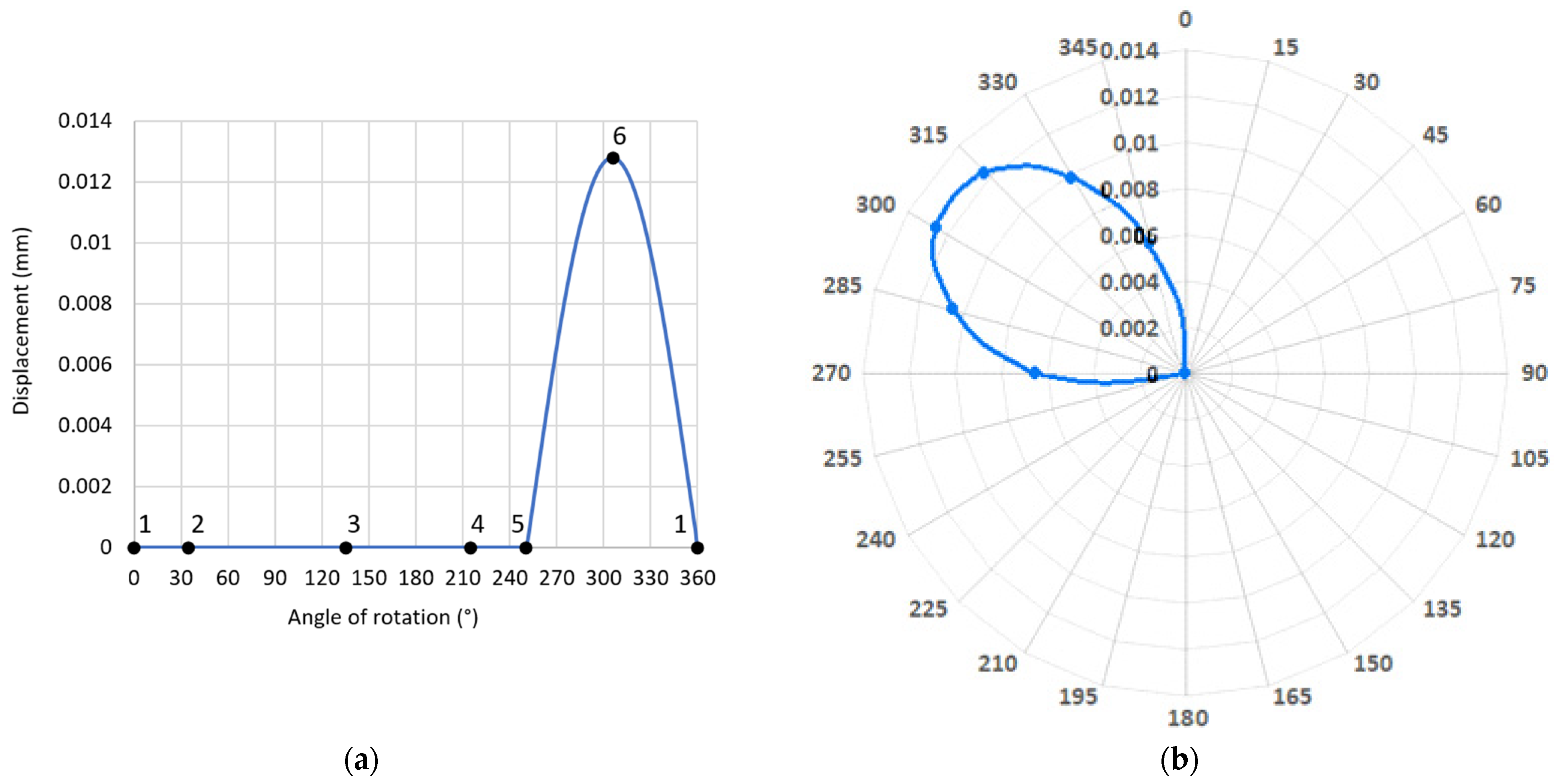
The results of this research formed the basis for the implementation of further studies presented in [18]. These were simulation and experimental studies. In this paper, it was shown that the specific case causing limitations in the detection of geometric deviations was the case when the crankshaft with a journal axis position deviation is supported by a set of rigid prism supports located at a uniform height. This specificity was contained in the fact that in the range of crankshaft rotation angles, where there was constant contact between the journal and the support, the displacement values were zero. This further means that, in this range of crankshaft rotation angles, it is not possible to detect displacements of the journal resulting from its eccentric displacement relative to the axis of rotation realized by the measuring system. For this case, the successive phases of displacements of the journal center during its rotation every 90°, in the range from 0° to 360°, are shown in Figure 1a. The indications of the sensor measuring these displacements, presented in the Cartesian and polar coordinates, are illustrated in Figure 1b. In the presented analysis, it was assumed that the eccentricity is 0.03 mm and that the journal in the initial angular position is at its upper maximum position.
As has been made apparent in cases where the support limits the crankshaft displacement, it is not possible to detect the full eccentricity of the journal. Recalling the symbols used in [18], in the case of the occurrence of eccentric displacement of the journal axis during crankshaft rotation, the values of the measured quantity w are directly affected by the eccentricity e, the height location of the support marked with the symbol x, and the location of the journal outline measured relative to the profile representing the journal axis displacement. In order to be able to correctly assess the geometric deviations, it is of strategic importance to interpret the harmonics, which are the Fourier expansions of the mathematical function describing the measured profile. This applies, in particular, to the harmonics assigned to the profile representing the measured incomplete eccentricity (depicted as a ‘truncated cosine’ as in the previously presented Figure 1b. Such a profile can be written as the sum of the expressions of a trigonometric Fourier series containing the first and subsequent harmonic components with even numbers.
Based on the results of the research carried out and using a scientific foundation in metrology, procedures and applications were proposed to support the measurements of crankshafts. The use of these procedures and applications for the assumed support conditions, which involve supporting the crankshaft with a set of supports located at equal heights, made it possible to correctly assess the geometric condition of the crankshaft. The effectiveness of the application of the developed solutions is presented on the example of practical measurements of the geometric deviations of the test object, which was the crankshaft of a medium-speed marine main drive engine. The measurement method shown can be successfully applied to any engine powered by alternative fuels.
The results presented in [18] did not completely resolve the issues discussed. The research focused on the specific case of the influence of the location of supports on the measurements of geometric deviations. This was a case in which the supports are situated at a uniform height, while the crankshaft is subjected to deviations in the position of the main journal axes. From the practical point of view, a more general case should be assumed, one in which the supports, in order to avoid the introduction of elastic deformations into the crankshaft, are initially located at different heights. The solution to this problem was set as the aim of this paper. The thesis that, in the case of measurements of the crankshaft burdened by deviations in the position of the main journal axes and the limitation of the possibility of detecting its geometric deviations resulting from the adopted support conditions, knowledge of the initial positioning of the supports will make it possible, on the basis of the measured total profile, to correctly determine the actual values of the geometric deviations of the crankshaft.
This paper describes experimental and simulation studies. The experimental part was carried out on a test stand enabling measurements of the crankshaft with reference and non-reference methods [20] with various variants of its support. The test stand was equipped with supports with the possibility of precise height positioning. These supports were additionally equipped with force measurement sensors. Thanks to this solution, it was possible to additionally measure the reaction forces at the contact between the support heads and the main journals of the crankshaft. The experimental tests were supplemented by simulation studies using the finite element method (FEM), which is often used in the numerical analysis of marine crankshafts [21,22]. The Midas NFX 2021 system [23] was implemented for the simulations. These included modelling the deformations and reaction forces on the crankshaft supports with deviations in the position of the main journal axes.

2. Research Problem

Taking into account that, in the case of a multi-supported crankshaft with deviations in the shape and the position of the main journal axes, a total profile is measured, the need to separate the measured values becomes a key issue. In other words, the results of the discrete amplitude spectrum for the summary profile can be used to determine the harmonic components associated with the outline of the journal shape and belonging to the eccentric displacement record of the journal axis.
The limitation of the possibility of eccentric displacement of the journal center resulting from the support conditions adopted with a set of supports located at different heights, causes that the profile image describing these displacements corresponds to the ‘truncated cosine’, as in previous analyses.
To fully illustrate the nature of the displacements, Figure 2 shows the journal displacements for successive characteristic angular positions of the journal, denoted by numbers one to six, assuming a counter-clockwise direction of the shaft rotation. In the angular positions numbered two, three and four, a change in the location of the center of the considered journal O1, with respect to the axis of rotation O of the remaining main journals, is accompanied by elastic deformations of the crankshaft cranks, hence the centers O1, O and the eccentricity for these angular positions are related by an additional mediating element characterizing the flexural compliance of the crankshaft.
Graphs illustrating the displacement path of the sensor stylus, presented in Cartesian and polar coordinate systems, are shown in Figure 3a,b, respectively. In the case under consideration, it was assumed that the eccentricity value e = 0.03 mm and that the center of the journal in the initial angular position was at the point marked 1 (Figure 2). The support, in order to maintain contact with the journal, is shifted upwards in relation to the others by a value of x = 0.017 mm. As a result, the eccentricity corresponding to the segment OO1 in the initial angular position of the crankshaft (rotation angle 0°) is deviated to the left by an angle of 55° with respect to the vertical direction. The measurable eccentricity value in this case is w = 0.013 mm.

3. Solution to the Problem

3.1. Determination of Geometric Deviations of Crankshafts with Limited Possibilities of Their Detection Resulting from the Adopted Support Conditions

As highlighted earlier, the amplitude spectrum of the eccentric displacement profile of the journal burdened by axis position deviation, when the supports are located at equal height, includes the first component and subsequent harmonic components with even numbers. This property was discussed in an earlier publication of the authors [18,19]. In the case analyzed, where the supports are positioned at different heights, the amplitude spectrum of the outline of eccentricity (Figure 3) has harmonic components with even and odd numbers [1,4,24,25,26,27,28,29].
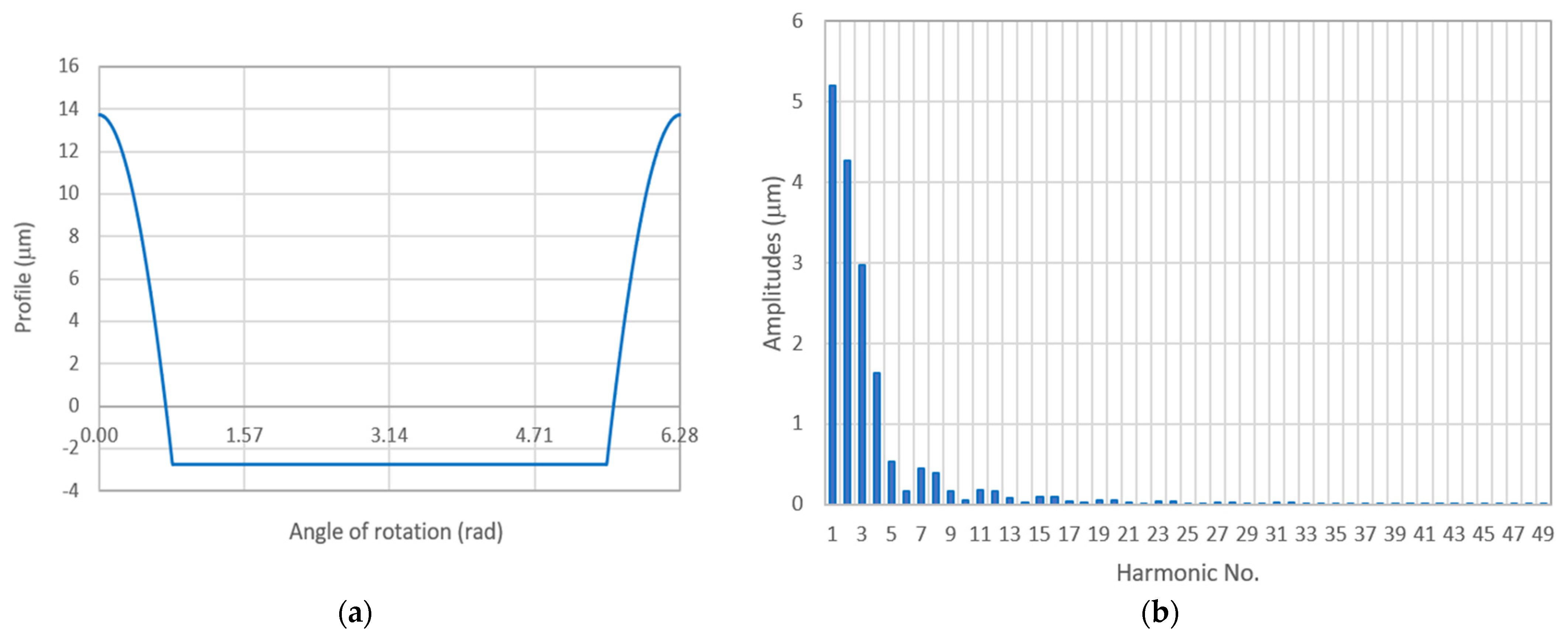
Figure 4 and Table 1 shows, as an example, the changes in the values of the first nine harmonics assigned to the profiles obtained by the ‘truncations’ every 1 µm of cosine waves with a full outline and amplitude equal to 10 µm. By carrying out this operation, outlines of eccentricity corresponding to various variants of the support positioning were obtained. The values of the amplitudes of the individual harmonic components increase in direct proportion to the change in the amplitude value corresponding to the recording of the full cosine. Thus, for any profile corresponding to the recording of the full eccentricity, it is possible to determine the harmonic components of the profiles corresponding to the recording of the measured incomplete eccentricity occurring in the case when the supports, to ensure contact with the journals, are located at different heights before the measurement.
Most of the harmonics describing the outline of eccentricity are unknown, as they are contained in the harmonics of the summary profile. It can be assumed, however, that with the results of the harmonic analysis for the summary profile, the value of the first harmonic is directly related to the profile representing the movement of the journal axis. The value of this amplitude is therefore assigned to the ‘truncated’ cosine profile or the vertical displacement of the support, which is displaced in relation to the other supports located at the same height. Hence, the research problem can be reduced to the search for a method of determining the unknown values of the remaining harmonics describing the outline of eccentricity from the amplitude spectrum of the summary profile.
It can also be assumed that, irrespective of the support conditions adopted, the measurable quantity is the mutual vertical positioning of the supports x. This quantity is related, as already mentioned above, to the measured profile representing the movement of the journal axis with a value w, whose first harmonic component C1 of the amplitude spectrum is a known quantity, since it is obtained from the amplitude spectrum of the measured summary profile.
A graphic interpretation of selected terms and quantities used so far in the text of the paper is presented in Figure 5. It shows the change in the shape of measurable eccentricities (depicted as ‘truncated cosine’ bounding the hatched fields), depending on the displacements of the support corresponding to the x-segments, with the actual value of the eccentricity equal to section e. The measurable eccentricity values correspond to the changes of the sections w.
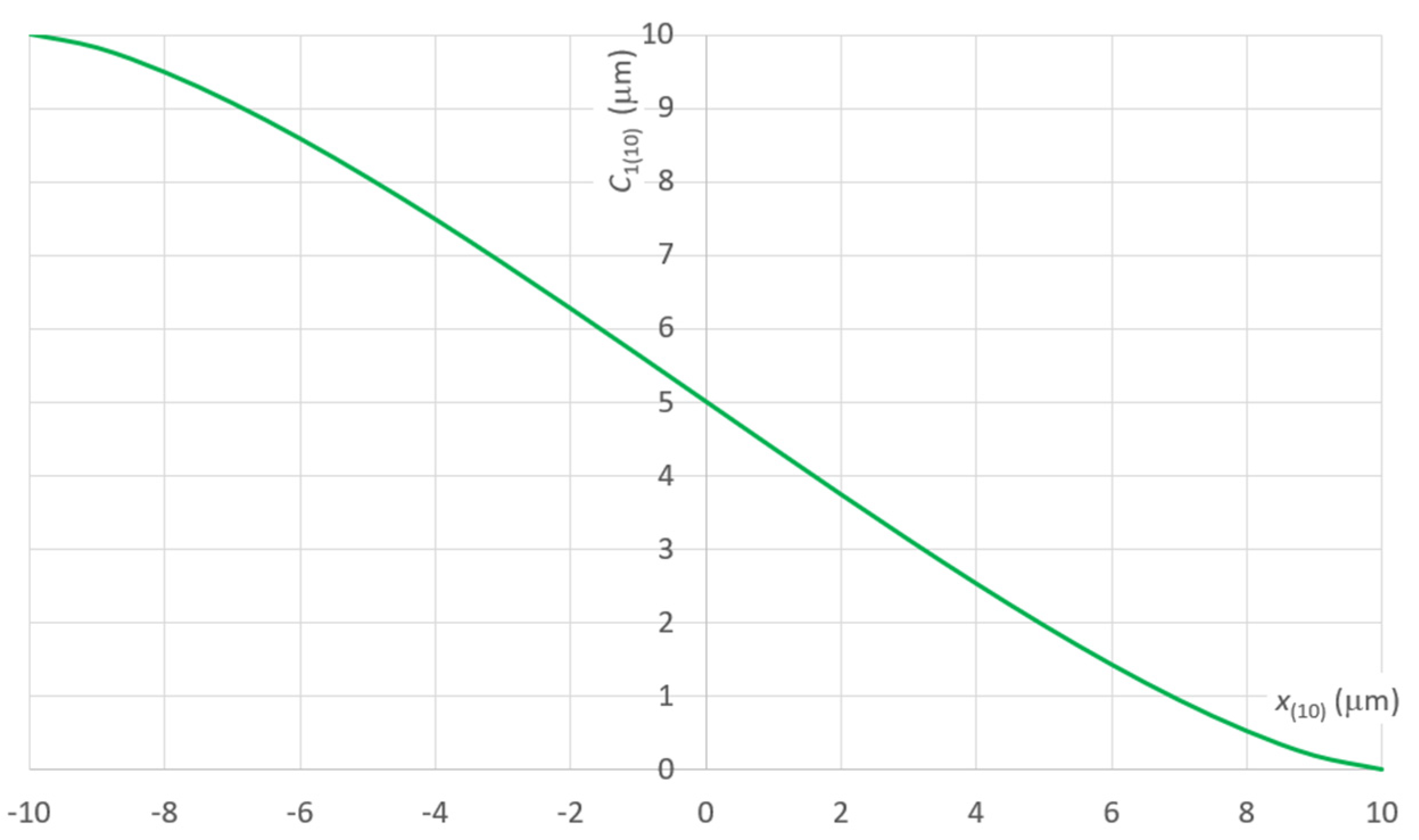
Figure 6 shows the variation of the amplitude value of the first harmonic component C1(10) of the amplitude spectrum of the outline of eccentricity as a function of the displacement of the support x(10), assuming that the eccentricity value e(10) = 10 μm.
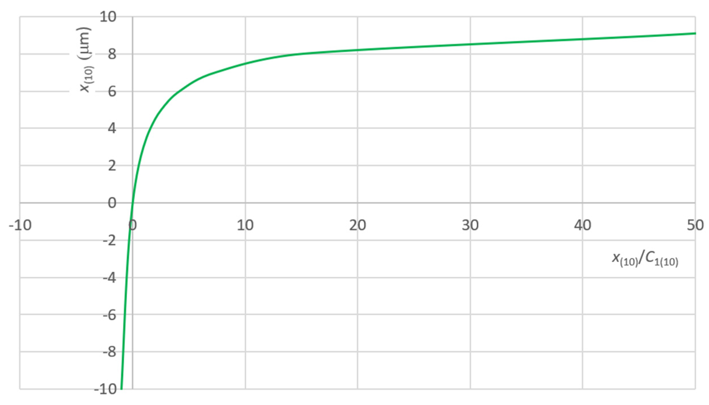
An excellent form of presentation is to express the chosen parameter x or C1 as a function of the x/C1 ratio. Figure 7 shows the variation of the parameter x(10) as a function of the x(10)/C1(10) ratio, assuming that the eccentricity value e(10) = 10 μm.
The quotients xi/C1i for any eccentricity ei are equal to the respective quotients x(10)/C1(10) at eccentricity e(10) = 10 μm. Indeed, the relationships apply: xi = n·x(10), C1i = n· C1(10), ei = n·e(10), where n is the multiplicity of the incidence of x(10), C1(10) and e(10) in xi, C1i and ei respectively.
Hence, taking eccentricity e(10) = 10 μm as a starting value, it is possible, for any xi its corresponding component C1i, to calculate the quotient xi/C1i and compare it to the known value of the quotient x(10)/C1(10).
The application of this approach makes it possible to determine the actual eccentricity value ei from knowledge of the displacement of the support xi and the amplitude of the first harmonic component C1i, which is one of the components of the amplitude spectrum describing the outline of eccentricity obtained when limiting journal displacement by a support positioned at a displacement xi relative to the other supports on which the main journals of the measured crankshaft are seated.
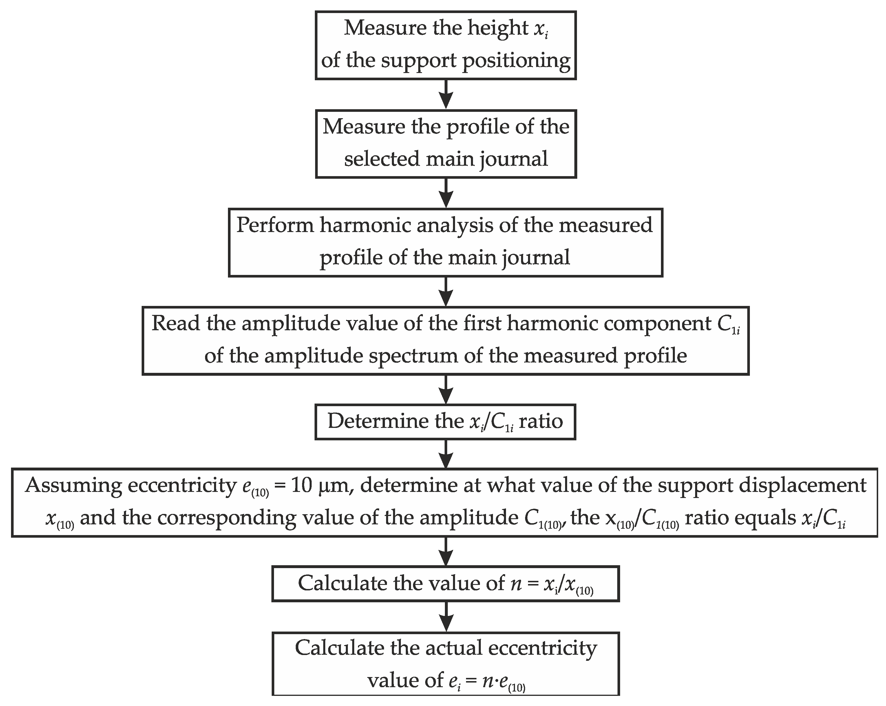
A procedural algorithm to determine the actual eccentricity value ei from the known parameters xi and C1i is shown in Figure 8.
Using the procedures included in the algorithm, it is possible to select the harmonics describing the journal displacements and the harmonics describing the actual journal roundness profile from the amplitude spectrum of the measured summary profile.

3.2. Exemplary Procedures for Determining the Theoretical Roundness Profile on the Basis of the Measured Summary Profile

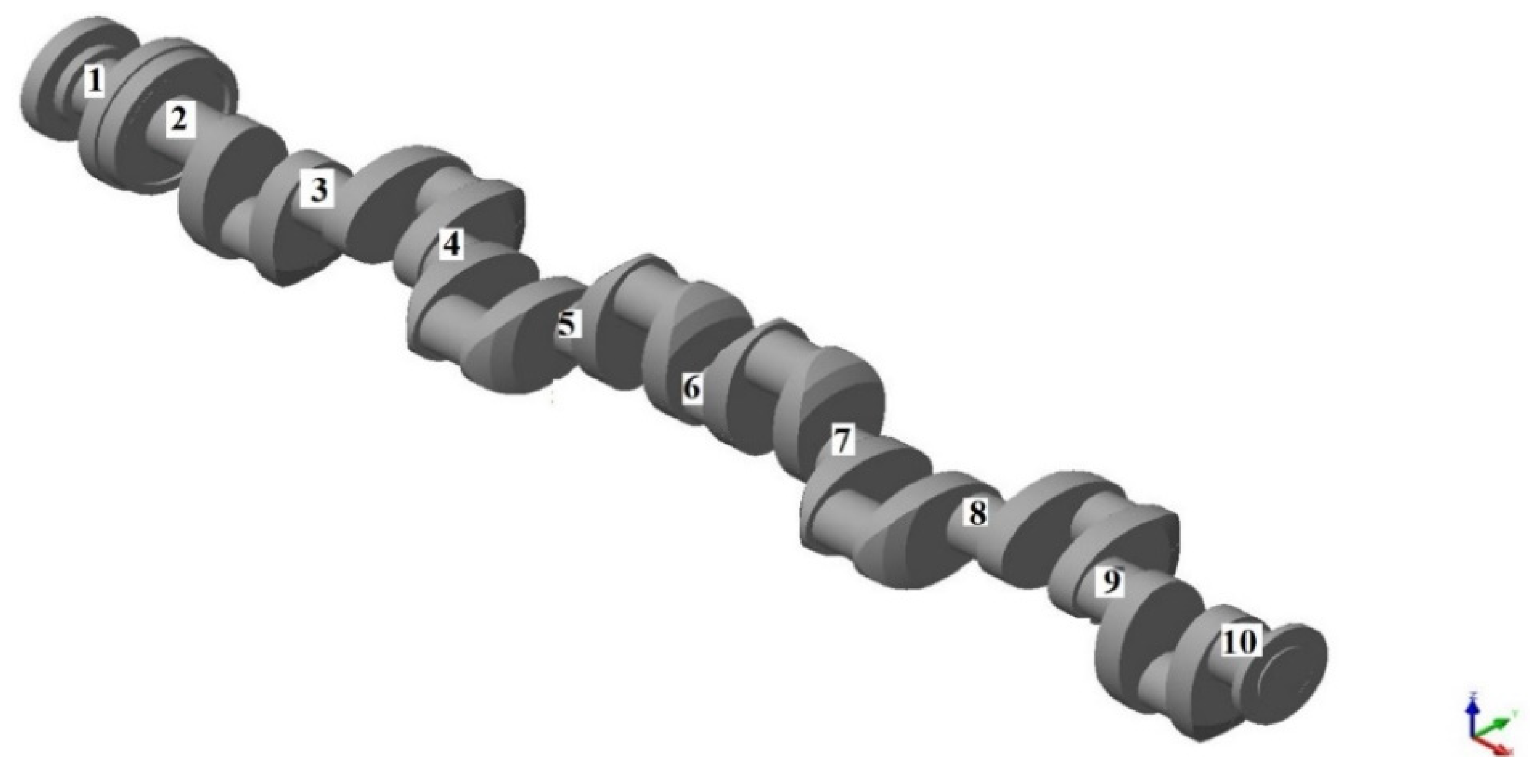
In order to verify the functioning of the developed procedures for determining the theoretical roundness profile from the measured summary profile, the deviations and outlines of the shape of the crankshaft main journal assembly adopted for the experimental study were measured. The object adopted for the study was the crankshaft of a marine main propulsion reciprocating energy machine. The crankshaft is shown in Figure 9 with the numbering of its main journals. The crankshaft was 3630 mm long, weight 9280 N, had ten 149 mm diameter main journals and eight 144 mm diameter crank journals.
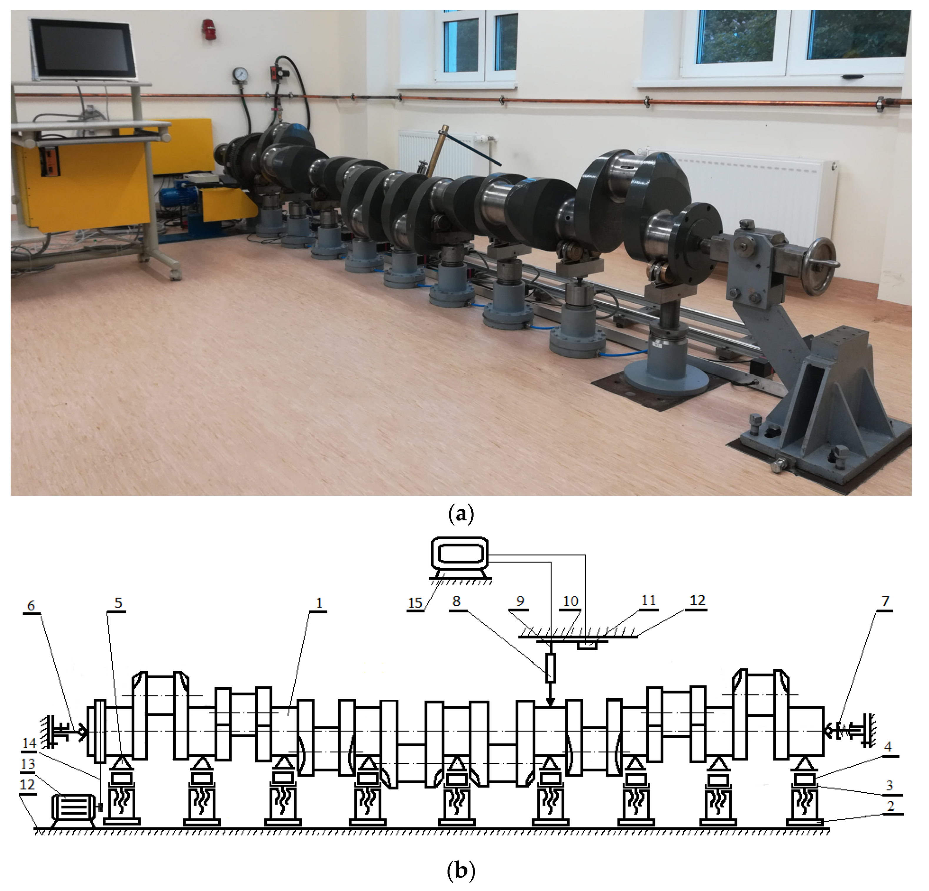
The measurements were made on a test stand equipped with a set of so-called ‘flexible supports’ presented in Figure 10.
The presented test stand is innovative, has no equivalent worldwide and is covered by Polish patent PAT.218653 [30]. It has been successively developed and is now a fully computerized stand for the measurement of large crankshafts. It is characterized by a high degree of versatility and it enables measurements of the crankshaft with reference and non-reference methods with various support variants. The support heads, which are mounted on pneumatic cylinders, are equipped with a screw mechanism enabling their precise height positioning. These supports are additionally equipped with force measurement sensors. This enables measurement of the reaction forces at the contact between the support heads and crankshaft journals. The support heads do not limit journal displacements in the horizontal plane. They are made in the so-called ‘floating’ version. The test stand is equipped with a system for measuring geometric deviations of the crankshaft. The measuring system consists of a trolley with a tripod mounted on it, a measuring sensor, and additionally, a laser distance meter. The system is able to move freely along the crankshaft on precision guides. The tripod with the sensor is pendulum-mounted on the support plate of the trolley, and the sensor can be moved along the tripod. This allows for precise positioning of the sensor in height and angle in relation to the measured journal profile. The measurement results are processed using SUPPORT-DEVFORMLOC, a proprietary calculation program, which combines the procedures for selection of support conditions and the elaborating their results. Due to the fact that the simplifying assumptions made in the development of mathematical models can be a source of method errors, this program performs the necessary calculations taking into account the quantities affecting the accuracy of measurements, including systematic and random errors. The data processing procedures concern both the determined deviations of the shape and the position of the axis [4,19,31,32].
It should also be emphasized that the scope of previous studies included the determination of optimal parameters for the method, which among other things included the angle determining the direction of the sensor’s stylus movement in relation to the measured profile. These studies allowed to establish single-sensor measurement systems characterized by the most favorable parameters in terms of the adopted criteria and their suitability for detecting deviations in the axis position and components of roundness outlines in the most commonly used range of 2–15 waves per circumference, as well as in the range of 15–50 waves per circumference, including some components of surface waviness [31]. These results coincided with those of similar studies reported in [4,33]. The use of these parameters in single-sensor systems allows for measurements to be carried out in accordance with the recommendations of modern metrology and guaranteeing the greatest possibility of detecting various geometric deviations.
The measurement strategy was based on measuring the shape outlines of the main journal assembly of the measured crankshaft and using the mean square element as the reference element used to determine both the shape deviations and the position of the axis. A diagram illustrating the measurement strategy adopted is presented in Figure 11.
The necessary mathematical apparatus adapted to the assumptions resulting from the measurement procedures adopted, based on the harmonic analysis of shape outlines, was used to determine the desired quantities.
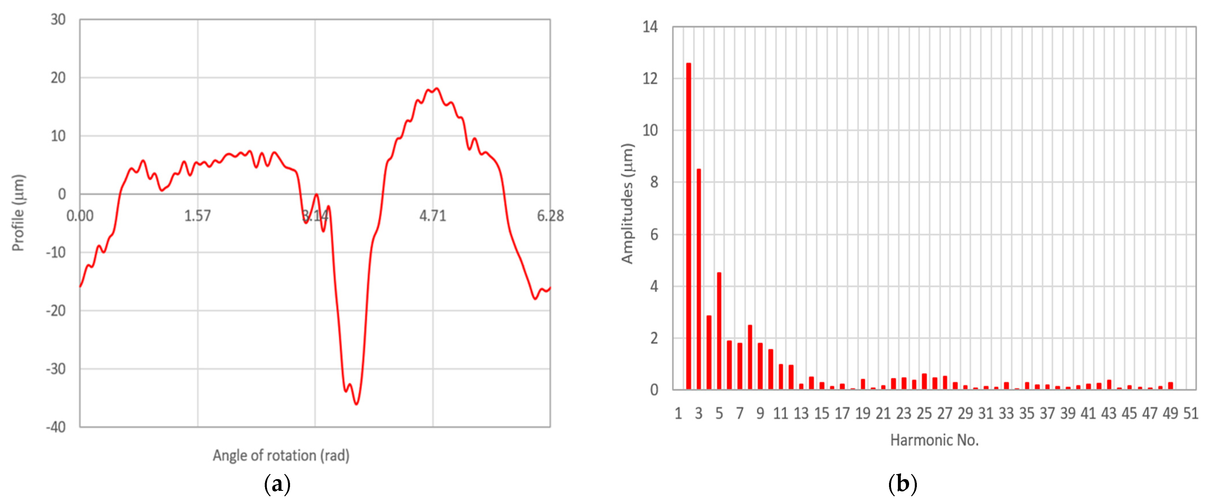
Figure 12a shows the measured summary profile, containing the journal profile No. 4 with an unknown value of eccentricity e.
Measurements have shown that, in the initial angular position of the crankshaft, in order to ensure the contact of the support with the measured journal, it must be shifted upwards in relation to the others by the value x = 38.5 μm.
The amplitude spectrum prepared for the summary profile, with the amplitude values of the individual harmonics corresponding to those in Table 2, is presented in Figure 12b. The first harmonic component of this spectrum has the value C1 = 5.1963 μm.
The quotient x/C1 = 7.4091 (Figure 7), to which the eccentricity e(10) = 10 μm, corresponds x(10) = 7 μm and C1(10) = 0.9448 μm (Figure 6). Since x/x(10) = 5.5, the actual eccentricity e in this case is equal to 5.5e(10), or 55 μm. The measurable eccentricity, on the other hand, corresponds to the value w = e—x = 16.5 μm (Figure 5). The graphical presentation of changes in the measured outline of eccentricity contained in the summary profile, however, can be illustrated as an incomplete cosine shown in Figure 13a or as a discrete amplitude spectrum as in Figure 13b. The values of individual harmonics are summarized in Table 3.
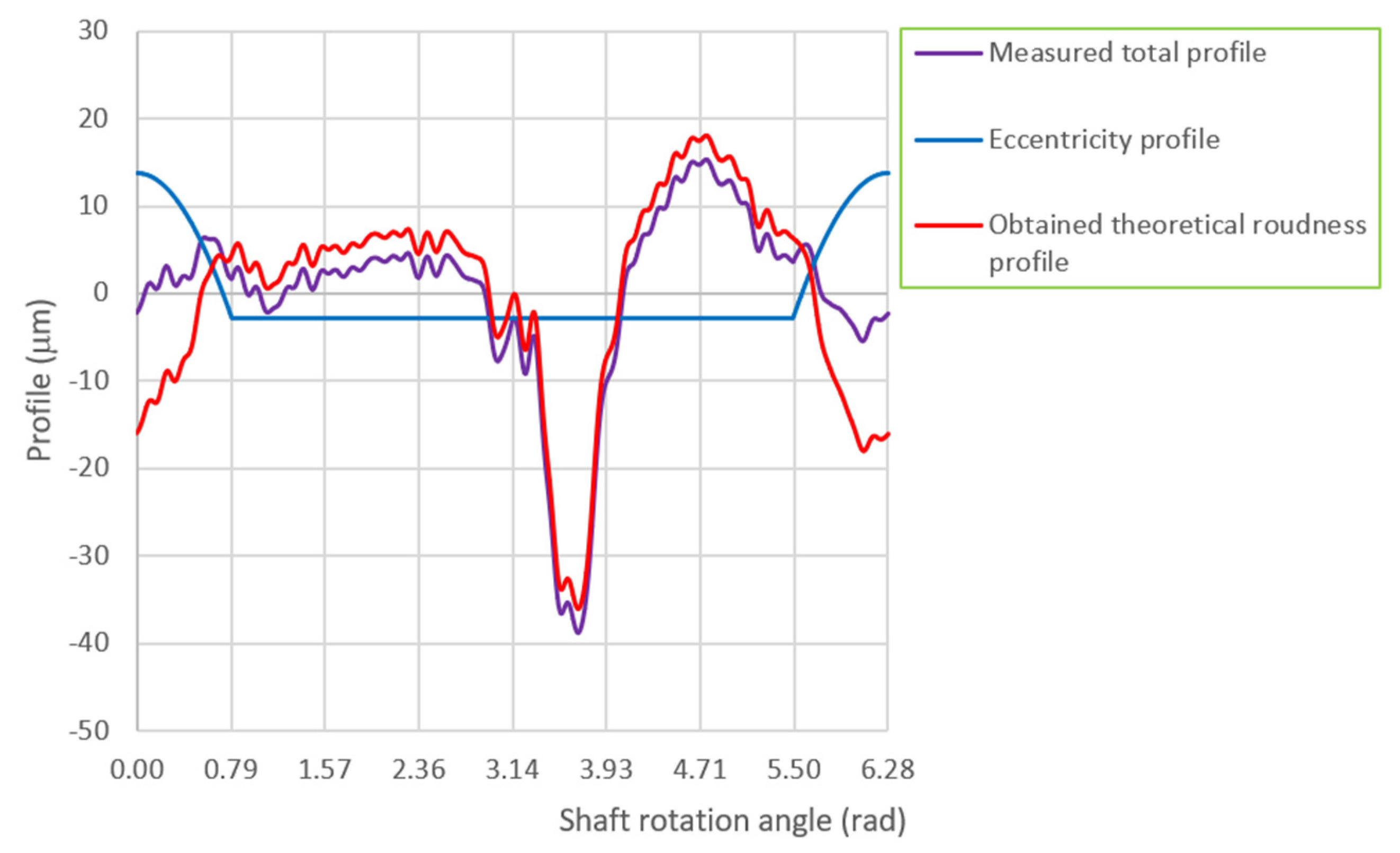
Elimination of the harmonic components assigned to the outline of eccentricity from the amplitude spectrum of the summary profile, as a result, enables the determination of the harmonic components of the theoretical roundness profile of the measured journal. Such a profile for the considered journal No. 4 is shown in Figure 14a, and its amplitude spectrum in Figure 14b.
The values of the individual harmonic components of the amplitude spectrum of the theoretical roundness profile of the journal No. 4 are presented in Table 4. The collective list of journal profiles No. 4, enabling their comparative assessment for the case under consideration, is presented in Figure 15.

3.3. Comparative Assessment of Test Results and Their Validation

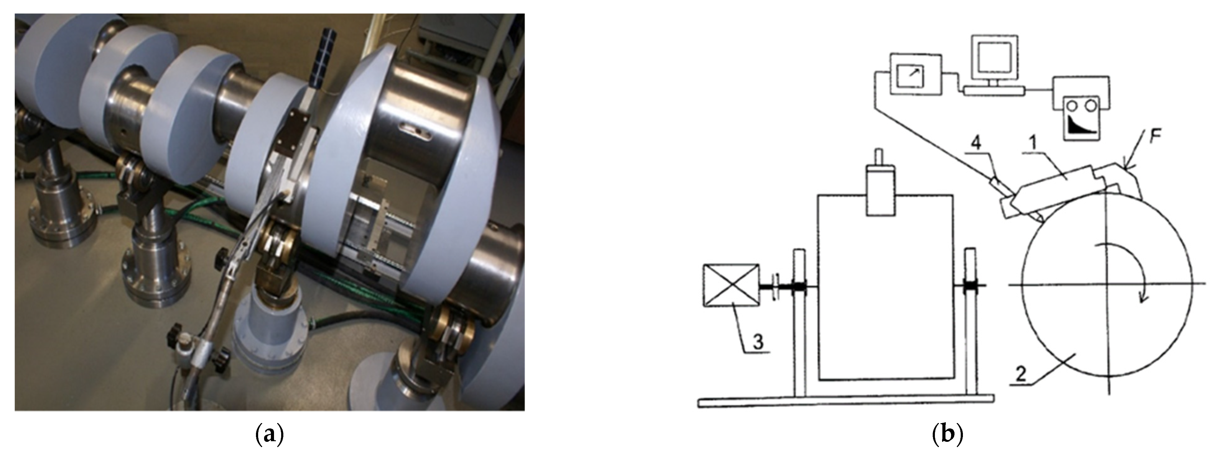
In order to enable a comparative assessment of the correctness of the theoretical roundness profiles obtained on the basis of the procedures proposed in Section 3.2, measurements were made of the standard deviations and outlines of the shape of the main journals of the object adopted for testing. The standard measurements of the deviations and outlines of the shape of the crankshaft journals were carried out with the use of a system with the MUK 25-600 measuring head and SAJD software, enabling full qualitative evaluation of the measured roundness outlines using the reference method [1,4,34,35]. The MUK 25-600 measuring head was seated directly on the surface of the tested journal during the measurements, so that the evaluation of the shape outlines was not dependent on the support conditions of the measured object (see Figure 16).
The roundness outlines measured in this way were subjected to harmonic analysis and comparative assessment with the results of measurements of the deviations and outlines of the journal shapes carried out on the test stand presented earlier (Figure 10). Measurements on the test stand were made by changing the angular position of the crankshaft, and accordingly, the height position of the supports on which the main journals of the measured crankshaft were mounted.
On the basis of the measurement results obtained, the roundness deviations values of the measured journals were specified. The determination of the roundness deviation RONt (roundness deviation) is based on the traditional method of its interpretation, in which it is assumed that in the case of its determination in relation to the mean circle, it is equal to the sum of the absolute values of the maximum height of elevation of the observed profile RONp (roundness peak) and the maximum depth of the cavity the observed profile RONv (roundness valley) [4,36,37]:
R O N t = R O N p + R O N v
The results of the application of the proposed procedures and reference measurements carried out in relation to the journals of the tested crankshaft showing eccentric displacements during its rotation are presented in Table 5. These journals are numbered four, five and seven, as in Figure 9.
Table 5 also shows the results of a comparative assessment between the theoretical roundness profiles obtained by applying the proposed procedures and the reference profiles for the previously listed journals (numbered 4, 5 and 7). The comparative assessment was carried out using correlation calculus and the intercorrelation factor ρ between compared profiles.
Corresponding circle outlines previously filtered in the harmonic range n = 2 ÷ 15, the referenced r1(φ) and the tested r2(φ), were subjected to a comparative evaluation, the measure of which was the value of the correspondence factor determined by a normalized intercorrelation function.
The normalized intercorrelation function is defined as follows [33]:
ρ ( γ ) = 2 0 2 π r 1 ( φ ) · r 2 ( φ + γ ) d φ 0 2 π r 1 ( φ ) 2 d φ + 0 2 π r 2 ( φ ) 2 d φ
The function was standardized so that:
1 ρ ( γ ) 1
whereby it can be proved that ρ(γ*) = 1 only if for a certain phase shift γ*:
r 1 ( φ ) = r 2 ( φ + γ * )
In practice, due to the limited accuracy of measuring instruments, the inequality ρ(γ) < 1 for each γ is usually true. Then, the value of γ* for which the function ρ(γ) assumes a maximum corresponds to the phase shift between the compared outlines, while the value of the intercorrelation function ρ(γ*) for the determined phase shift γ* can be regarded as the value of the compatibility factor between the compared outlines.
In light of the proposed comparative evaluation procedure, the determined value of the angle γ*, which corresponds to the phase shift between the analysed outlines, further allows a quantitative as well as a qualitative visual evaluation of the superimposed roundness outlines presented in a single diagram in the polar or Cartesian coordinate system.
The experimental results were supplemented by simulation studies of the deformations of the adopted test object subjected to axis position deviation and supported by a set of supports positioned at different heights. These studies were aimed at extending the experimental results presented so far and verifying the observations made indicating the possibility of measuring the so-called apparent eccentricity caused by elastic deformations of the crankshaft.
The simulation tests were carried out using the Midas NFX 2021 finite element system (Midas Information Technology Co. Ltd., Seongnam, Korea) [23]. The finite element mesh used in the analysis consisted of tetrahedral elements (CTETRA), characterized by three translational degrees of freedom at each node. The model consisted of 137,475 finite elements with 126,114 degrees of freedom. A steel with Young’s modulus E = 210 GPa, Poisson’s number ν = 0.28, and density ρm = 7900 kg/m3 was used as the material. A gravity load of 9300 N was applied to the model. The boundary conditions were modelled at the nodes corresponding to the journal supports. The support nodes in which the reactions occurred had one degree of freedom taken away (displacement in the vertical direction). The analysis was performed with a Nastran linear static solver (SOL101).
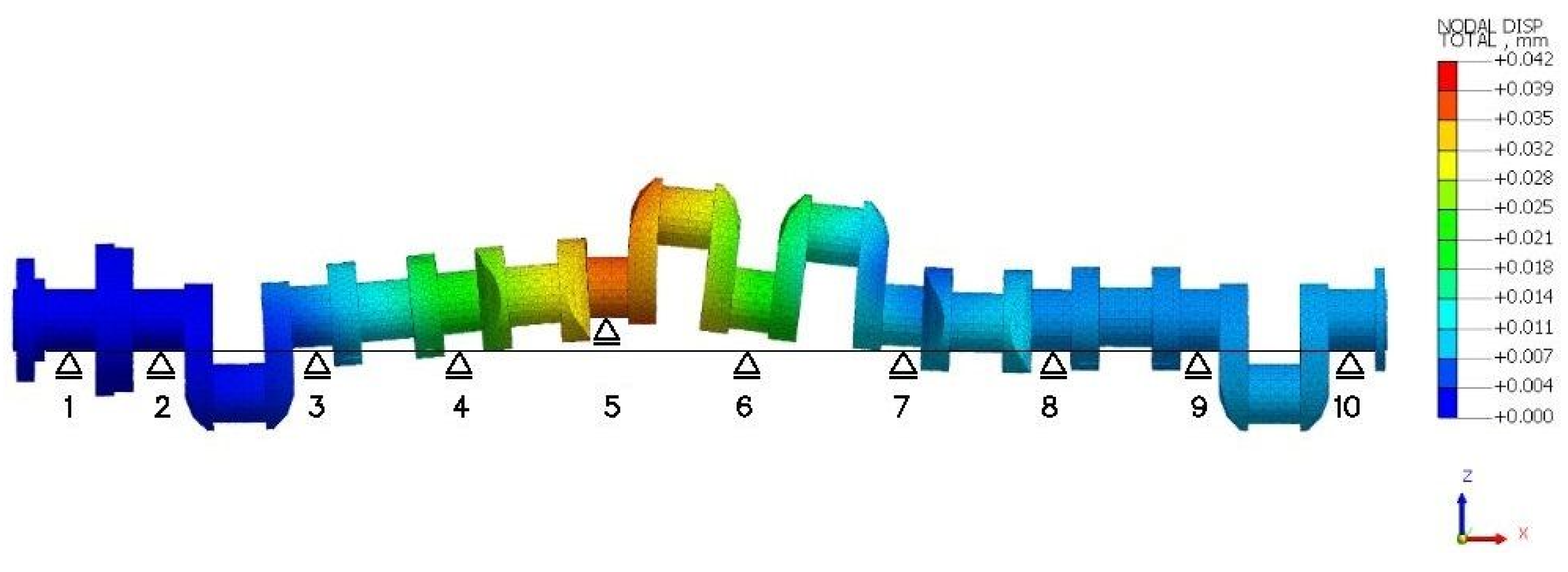
An example of crankshaft deformations obtained by FE-simulations for the case where one of the supports (supporting journal No. 5) is displaced upwards in relation to the others, is shown in Figure 17.
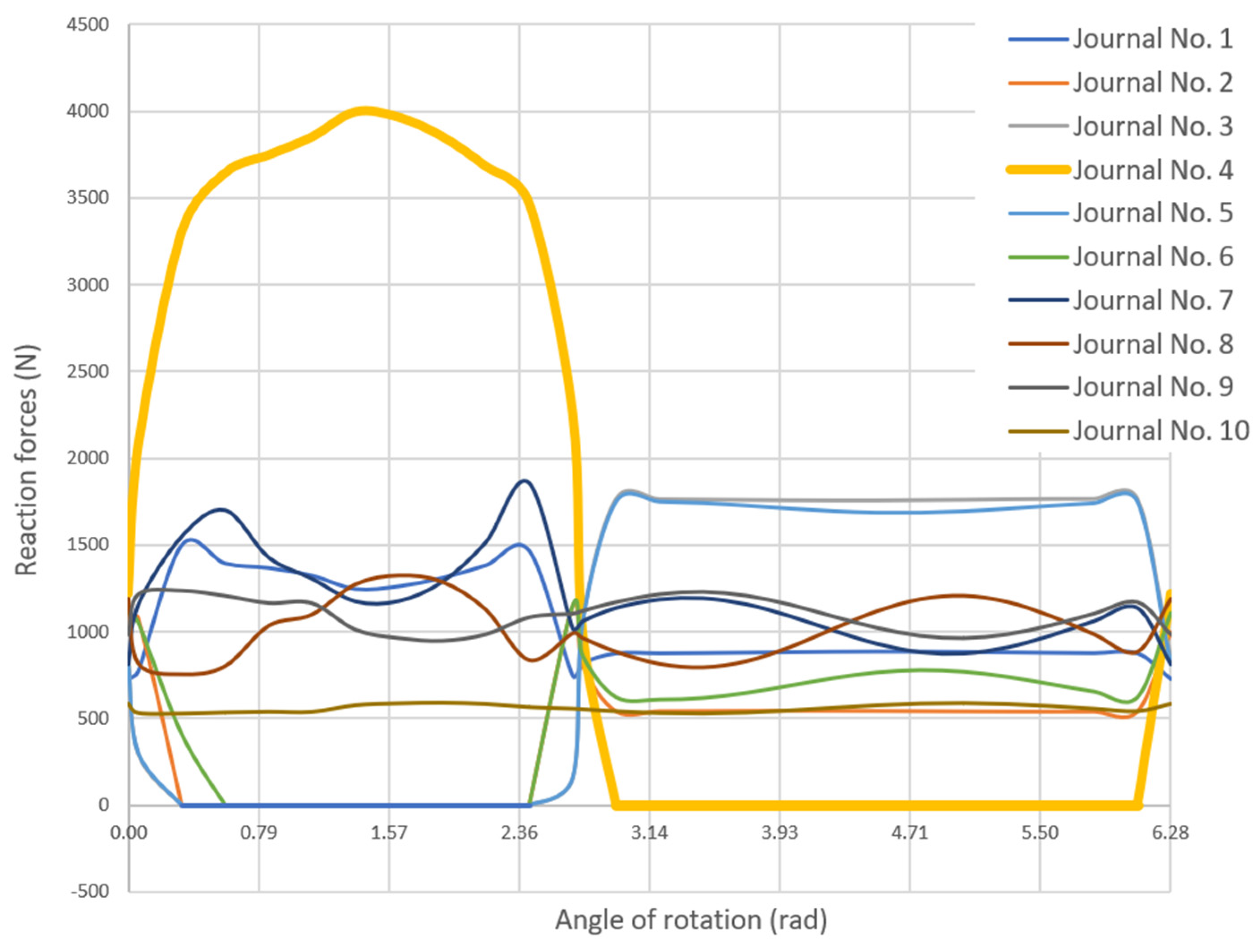
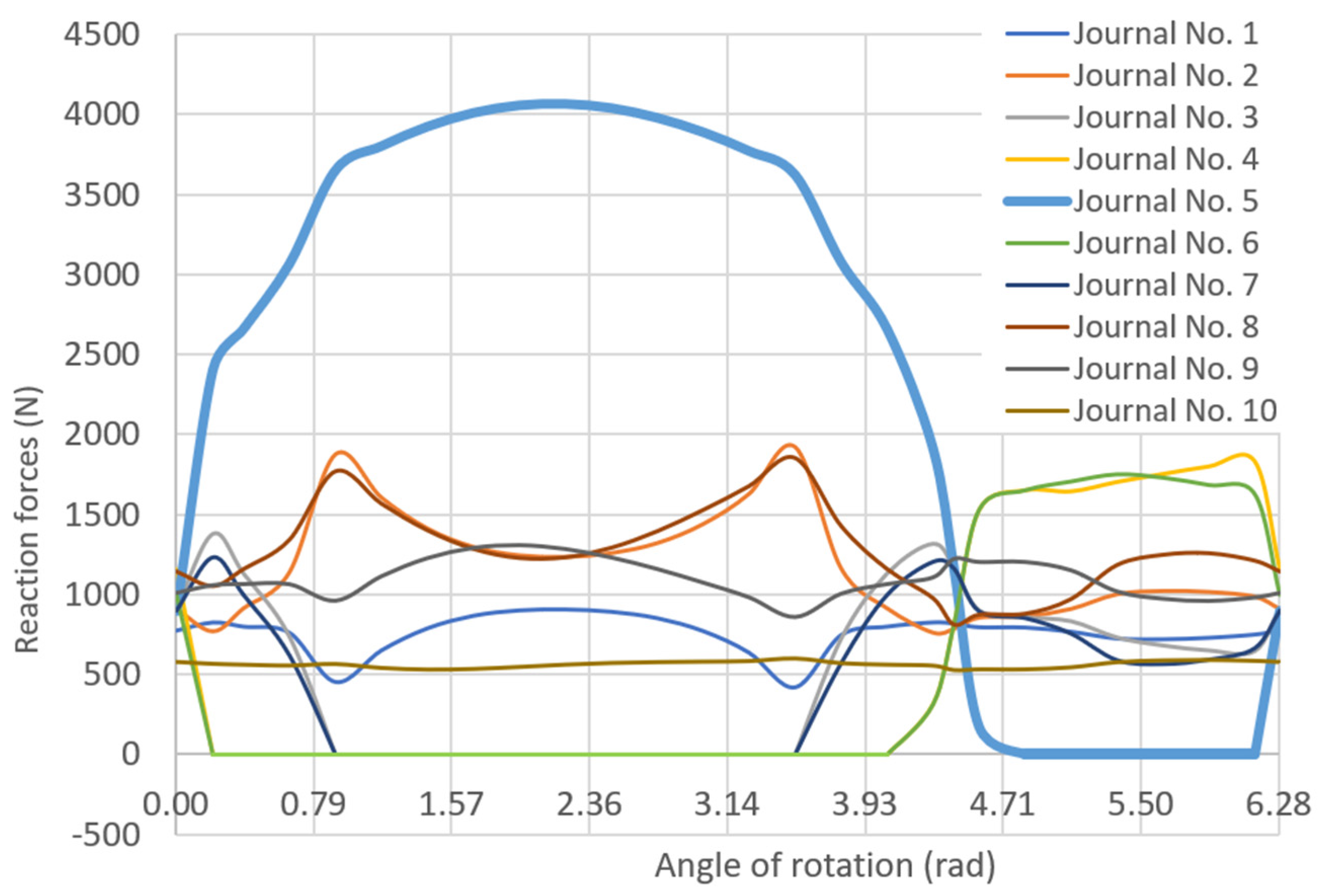
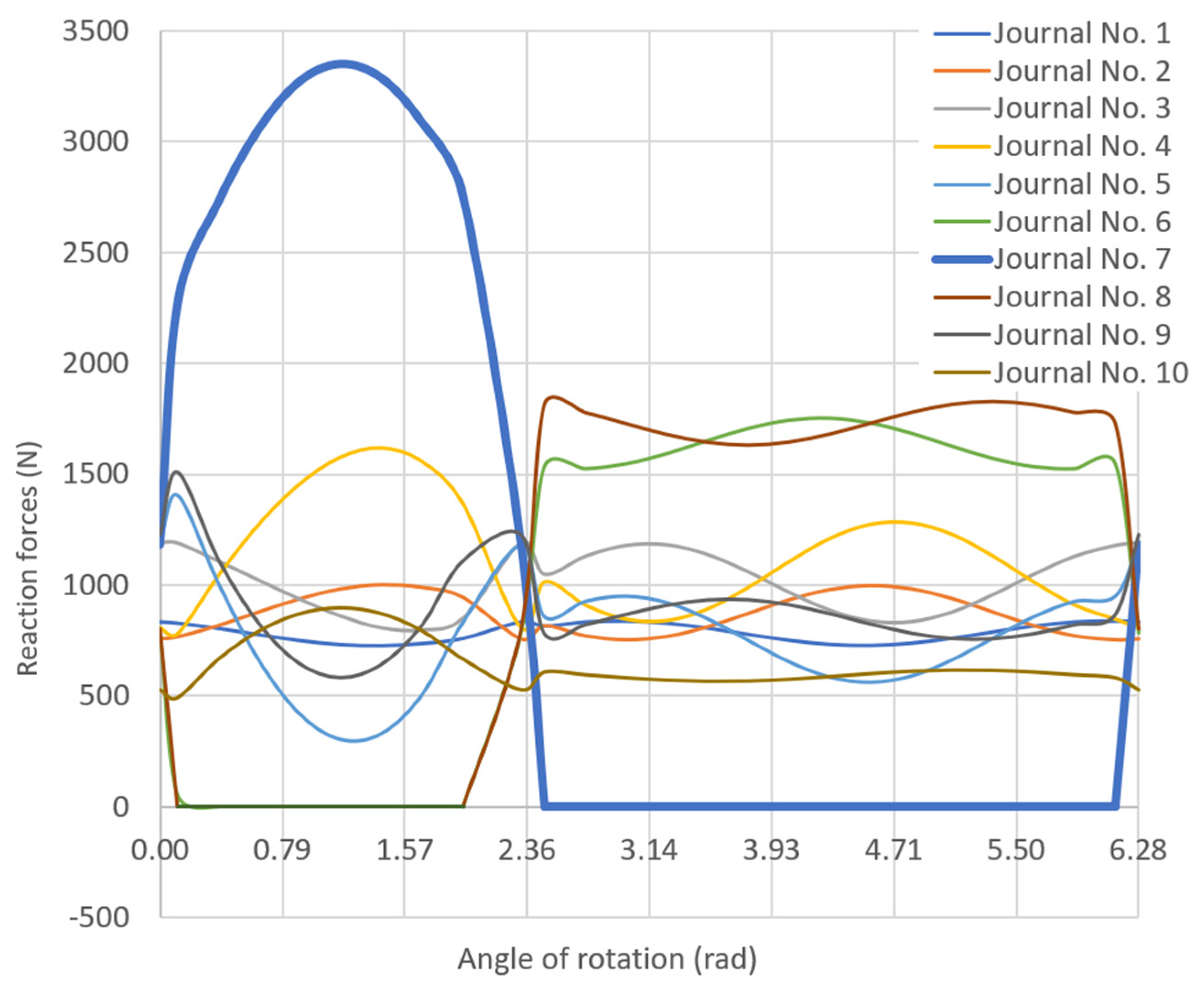
Simulation tests were also carried out to determine the reaction forces at the contact between the support heads and the main journals. For the assumed eccentricity of the journal, displacements of the journal were forced depending on the angle of rotation of the crankshaft [38]. This resulted in a periodic disappearance of the reaction forces on journals adjacent to the eccentricity-laden journal and a significant increase in reaction force when the journal maintained contact with the support. This is evidenced by the exemplary results of the calculation of reaction forces carried out for the selected measurement variants of journals four, five and seven (Table 5), which are presented in Figure 18, Figure 19 and Figure 20.
On the basis of the simulation results obtained, it can be concluded that the so-called ‘apparent eccentricity’ caused by elastic deformations of the crankshaft can be measured during measurements. Such a situation may occur in the case of a complex geometric state of the crankshaft being measured, or in the case of simultaneous measurement of all main journals with the use of multi-sensor systems. Therefore, in such cases, it is necessary to know the initial positioning of the supports as well as the reaction forces at the contact between the support heads and the main journals of the crankshaft. Knowledge of the reaction forces will make it possible to distinguish the measured ‘apparent eccentricity’ caused by elastic deformations of the crankshaft from the eccentricity resulting from its geometric state.

4. Conclusions

This paper presents the results of research aimed at improving the applied measurement techniques for large crankshafts of marine engines fueled not only with diesel but also with alternative (gas) fuels. As emphasized in the introduction, the basis for undertaking the research was verification of the thesis formulated at the beginning of the paper, which states that, in the case of crankshaft measurements burdened with deviations in the position of the main journals’ axes and the limitations in detecting its geometrical deviations resulting from the adopted support conditions, knowledge of the initial positioning of the supports will enable, on the basis of the measured summed profile, the actual values of geometric deviations of the crankshaft to be determined correctly.
The analyses carried out, supported by experimental studies, authorize the conclusion that the formulated research thesis has been verified with positive results and that the adopted aim of the study has been achieved. The studies also confirmed, once again, that the use of the traditional method of supporting the crankshaft with a set of fixed rigid supports causes limitations in the possibility of detecting its geometric deviations.
The result of the research work are the proposed procedures, which, in the case of support positioning at different heights, make it possible to eliminate the influence of the support conditions on the measured deviations and shape outlines of the crankshaft main journal assembly. A comparative analysis of the roundness profiles obtained as a result of the proposed procedures, determined on the basis of the measured summed profiles of the measured main journal assembly of the crankshaft adopted for the experimental tests showed their satisfactory agreement with the measurement results, which were taken as reference. The measure of the comparative assessment was the intercorrelation factor ρ, the minimum value of which was = 0.8982, while the maximum value was = 0.9751. The results obtained provide grounds for the optimistic conclusion that the application of the developed procedures in practical measurements will improve the measurement techniques used, thereby increasing the efficiency and reliability of a reliable assessment of the geometric condition of the crankshaft.
The results of simulation tests of the distribution of reaction forces on the main journals of a multi-location supported crankshaft confirmed that, in order to correctly interpret the measured geometric quantities, it is necessary to control the distribution of the reaction forces. This makes it possible to distinguish the measured so-called ‘apparent eccentricity’ caused by elastic deformations of the crankshaft from the eccentricity resulting from its geometric state.

Author Contributions

Conceptualization, K.N. and Z.G.; methodology, K.N. and Z.G.; software, K.N. and Z.G.; validation, M.N. and M.S.; formal analysis, K.N. and R.G.; investigation, K.N. and Z.G.; resources, K.N. and Z.G.; data curation, K.N. and Z.G.; writing—original draft preparation, K.N. and Z.G.; writing—review and editing, M.N., M.S. and R.G.; visualization, K.N., R.G. and Z.G.; supervision, K.N.; project administration, M.N. and R.G.; funding acquisition, K.N. and M.N. All authors have read and agreed to the published version of the manuscript.

Funding

This research received no external funding.

Data Availability Statement

Not applicable.

Conflicts of Interest

The authors declare no conflict of interest.

References

  1. Adamczak, S. Measurements of Geometrical Surfaces, Outlines of Shape, Waviness, and Roughness; WNT: Warsaw, Poland, 2008. (In Polish) [Google Scholar]
  2. Mekid, S.; Vacharanukul, K. In-process out-of-roundness measurement probe for turned workpieces. Measurement 2011, 44, 762–766. [Google Scholar] [CrossRef]
  3. Janusiewicz, A.; Adamczak, S.; Makieła, W.; Stępień, K. Determining the theoretical method error during an on-machine roundness measurement. Measurement 2011, 44, 1761–1767. [Google Scholar] [CrossRef]
  4. Stępień, K.; Janecki, D.; Adamczak, S. Fundamentals of adaptive strategy of cylindricity measurements with the use of longitudinal measurements. Meas. Sens. 2021, 18, 100146. [Google Scholar] [CrossRef]
  5. Liu, Y.; Mei, Y.; Sun, C.; Li, R.; Wang, X.; Wang, H.; Tan, J.; Lu, Q. A novel cylindrical profile measurement model and errors separation method applied to stepped shafts precision model engineering. Measurement 2022, 188, 110486. [Google Scholar] [CrossRef]
  6. Li, X.; Xu, K.; Wang, S. Precision measurement method of large shaft diameter based on dual camera system. Sensors 2022, 22, 3982. [Google Scholar] [CrossRef]
  7. Clader, N. Marine Diesel Engines: Maintenance, Troubleshooting, and Repair, 3rd ed.; International Marine/Ragged Mountain Press: Camden, UK, 2006. [Google Scholar]
  8. Shen, N.; Li, J.; Qian, X.; Huang, H. Precise alignment method of the large-scale crankshaft during non-circular grinding. Int. J. Adv. Manuf. Technol. 2015, 80, 921–930. [Google Scholar] [CrossRef]
  9. Nguyen, D.V.; Duy, V.N. Numerical analysis of the forces on the components of a direct diesel engine. Appl. Sci. 2018, 8, 761. [Google Scholar] [CrossRef] [Green Version]
  10. Kamiński, W. Marine slow-speed engines’ cylinder oil lubrication feed rate optimization in real operational conditions. Energies 2022, 15, 8378. [Google Scholar] [CrossRef]
  11. Łukomski, Z. Rail and Marine Internal Combustion Engine Technology; Transport and Communication Publishers: Warsaw, Poland, 1972. (In Polish) [Google Scholar]
  12. Chen, M.; Takahashi, S.; Takamasu, K. Development of high-precision micro-roundness measuring machine using a high-sensitivity and compact multi-beam angle sensor. Precis. Eng. 2015, 42, 276–282. [Google Scholar] [CrossRef]
  13. Grzejda, R. Finite element modeling of the contact of elements preloaded with a bolt and externally loaded with any force. J. Comput. Appl. Math. 2021, 393, 113534. [Google Scholar] [CrossRef]
  14. Shape and Position Tolerances of Crankshafts—Engine Technology, Specification; MAN B&W, H. Cegielski, S.A.: Poznan, Poland, 2010. (In Polish)
  15. IMO. Marine Engine IMO Tier II Programme; IMO: London, UK, 2013. [Google Scholar]
  16. MAN B&W 50-90 MC/MCE Engines Instruction Manual; MAN B&W Diesel A/S: Copenhagen, Denmark, 2013.
  17. Nozdrzykowski, K.; Adamczak, S.; Grządziel, Z.; Dunaj, P. The effect of deflections and elastic deformations on geometrical deviation and shape profile measurements of large crankshafts with uncontrolled supports. Sensors 2020, 20, 5714. [Google Scholar] [CrossRef] [PubMed]
  18. Nozdrzykowski, K.; Grządziel, Z.; Dunaj, P. Determining geometrical deviations of crankshafts with limited detection possibilities due to support conditions. Measurement 2022, 189, 110430. [Google Scholar] [CrossRef]
  19. Nozdrzykowski, K. Conditions and Criteria of the Correct Assessment of the Geometric Condition of Large Crankshaft; Maritime University of Szczecin Press: Szczecin, Poland, 2022. (In Polish) [Google Scholar]
  20. Chybowski, L.; Nozdrzykowski, K.; Grządziel, Z.; Jakubowski, A.; Przetakiewicz, W. Method to increase the accuracy of large crankshaft geometry measurements using counterweights to minimize elastic deformations. Appl. Sci. 2020, 10, 4722. [Google Scholar] [CrossRef]
  21. Vizentin, G.; Vukelic, G.; Murawski, L.; Recho, N.; Orovic, J. Marine propulsion system failures—A review. J. Mar. Sci. Eng. 2020, 8, 662. [Google Scholar] [CrossRef]
  22. Chen, L.; Xue, D.; Song, X.; He, Z.; Huang, D. A study on anti-shock performance of marine diesel engine based on multi-body dynamics and elastohydrodynamic lubrication. Appl. Sci. 2021, 11, 11259. [Google Scholar] [CrossRef]
  23. Midas Engineering Software. Available online: https://www.midasoft.com (accessed on 24 October 2022).
  24. Whitehouse, D.J. Handbook of Surface Metrology, 1st ed.; Institute of Physics Publishing: Bristol, England, 1994. [Google Scholar]
  25. Mohlenkamp, M.J. A fast transform for spherical harmonics. J. Fourier Anal. Appl. 1999, 5, 159–184. [Google Scholar] [CrossRef]
  26. Capello, E.; Semeraro, Q. The harmonic fitting method for the assessment of the substitute geometry estimate error. Part I: 2D and 3D theory. Int. J. Mach. Tools Manuf. 2001, 41, 1071–1102. [Google Scholar] [CrossRef]
  27. Kunis, S.; Potts, D. Fast spherical Fourier algorithms. J. Comput. Appl. Math. 2003, 161, 75–98. [Google Scholar] [CrossRef] [Green Version]
  28. Nozdrzykowski, K. Applying harmonic analysis in the measurements of geometrical deviations of crankshafts—Roundness shapes analysis. Multidiscip. Asp. Prod. Eng. 2018, 1, 185–189. [Google Scholar] [CrossRef] [Green Version]
  29. Muhammad, A.; Ali, M.A.H.; Shanono, I.H. Fatigue and harmonic analysis of a diesel engine crankshaft using ANSYS. In iMEC-APCOMS 2019; Osman Zahid, M.N., Abd Aziz, R., Yusoff, A.R., Mat Yahya, N., Abdul Aziz, F., Yazid Abu, M., Eds.; Lecture Notes in Mechanical Engineering; Springer: Singapore, 2020; pp. 371–376. [Google Scholar]
  30. Nozdrzykowski, K. Method and Device for Measuring the Deviation of Axis Shape and Position of the Crankshaft Pivot Set, PAT.218653, 10.06.2014; Polish Patent Office: Warsaw, Poland, 2014. [Google Scholar]
  31. Nozdrzykowski, K. Methodology of Geometric Measurements of Deviations of Cylindrical Surfaces of Large-Size Machine Elements Based on the Example of Ship Engine Crankshafts; Maritime University of Szczecin Press: Szczecin, Poland, 2013. (In Polish) [Google Scholar]
  32. Nozdrzykowski, K. Prevention of elastic strains in flexible large size machine parts with the use of elastic support. Mach. Dyn. Res. 2015, 39, 111–122. [Google Scholar]
  33. Adamczak, S. Reference Methods for Measuring the Roundness Profiles of Machine Parts; Kielce University of Technology: Kielce, Poland, 1998. (In Polish) [Google Scholar]
  34. Adamczak, S.; Janecki, D. Reference methods and their wider applicability to measurements of roundness profiles. Elektrotech. Inftech. 1998, 115, 197–202. [Google Scholar] [CrossRef]
  35. Adamczak, S.; Janecki, D.; Świderski, J.; Dobrowolski, T. Verification of Outlines of Crankshaft Pins Roundness Based on the MUK 25-600 Measuring System with SAJD Software, Research commissioned by the Maritime University of Szczecin; Kielce University of Technology: Kielce, Poland, 2011. (In Polish) [Google Scholar]
  36. Whitehouse, D.J. Handbook of Surface and Nanometrology, 2nd ed.; CRC Press: Boca Raton, FL, USA, 2010. [Google Scholar]
  37. PN-EN ISO 12181-2, 2012; Geometrical Product Specifications (GPS), Roundness, Part 2: Specification Operators. Polish Committee for Standardization: Warsaw, Poland, 2012.
  38. Nozdrzykowski, K.; Grządziel, Z.; Grzejda, R.; Warzecha, M.; Stępień, M. An analysis of reaction forces in crankshaft support systems. Lubricants 2022, 10, 151. [Google Scholar] [CrossRef]
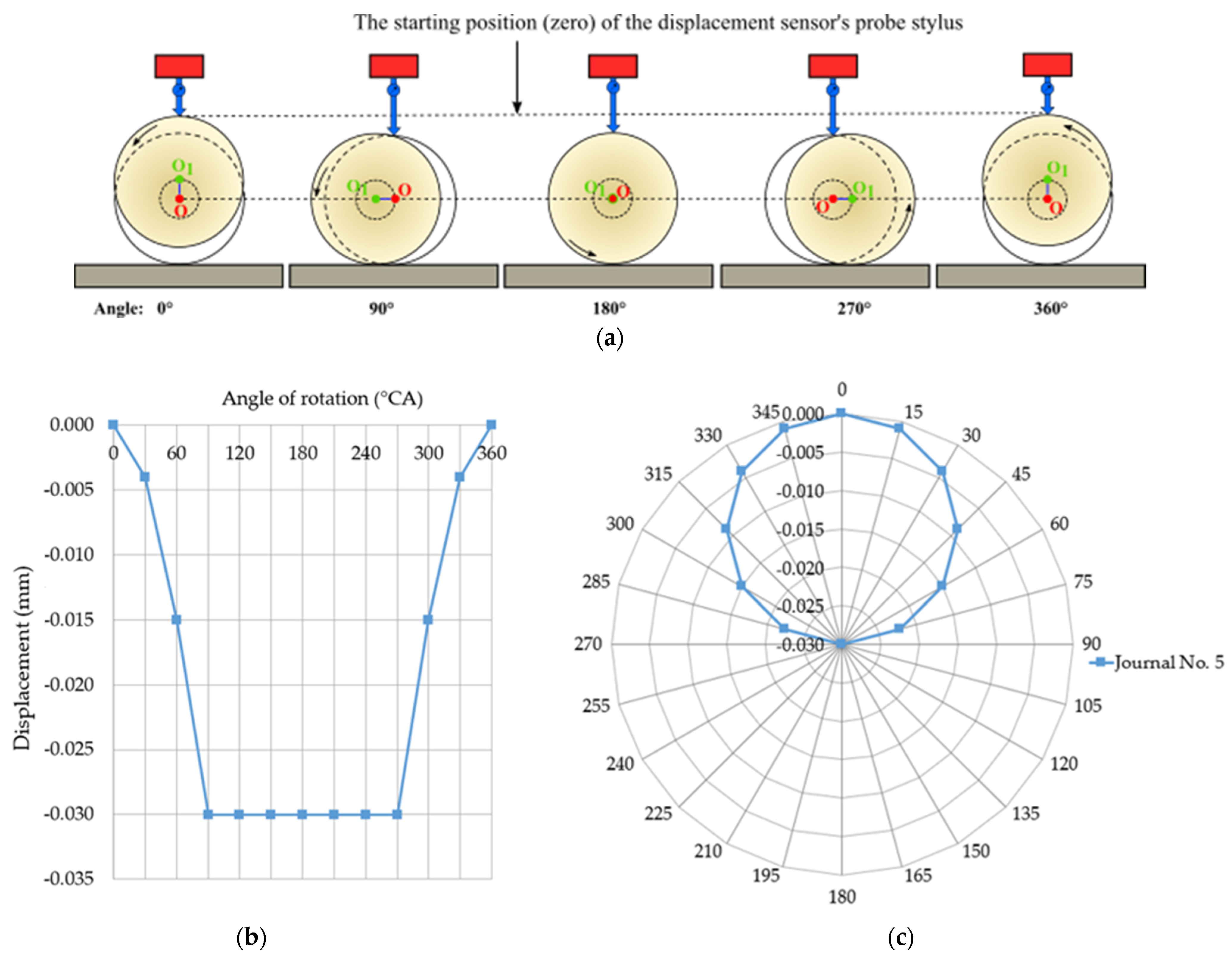
Figure 1. Indications of the sensor when measuring journal displacement over the full range of crankshaft rotation from 0° to 360° recorded at a constant heigh position of the support (a); limits shown in Cartesian coordinates (b); limits shown in polar coordinates (c) [17,18,19].
Energies 16 00016 g001
Figure 2. Diagram showing the successive stages of displacements of a journal with eccentricity during crankshaft rotation, for the case where the support is initially positioned upwards in relation to the others (x—support displacement, OO1 = e—eccentricity, w—measurable eccentricity).
Energies 16 00016 g002
Figure 3. Graphs showing the displacement path of the sensor stylus presented in: (a) Cartesian coordinates; (b) polar coordinates (support offset x = 0.017 mm, eccentricity e = 0.030 mm, measurable eccentricity w = 0.013 mm).
Energies 16 00016 g003
Figure 4. Variation of the amplitudes of the first nine harmonics as a function of the ‘truncations’ every 1 μm of a full cosine with an amplitude of 10 μm.
Energies 16 00016 g004
Figure 5. Graphical interpretation of quantities: w—measurable eccentricity, x—support displacement, e—eccentricity.
Energies 16 00016 g005
Figure 6. Variation of the value of the amplitude of the first harmonic component C1(10) of the amplitude spectrum of the outline of eccentricity depending on the displacement of the support x(10), assuming that the eccentricity value e(10) = 10 μm.
Energies 16 00016 g006
Figure 7. Variation of the parameter x(10) as a function of the x(10)/C1(10) ratio, assuming that the eccentricity value e(10) = 10 μm.
Energies 16 00016 g007
Figure 8. Algorithm for determining the actual eccentricity value ei from the known parameters xi and C1i.
Energies 16 00016 g008
Figure 9. Modelled medium-speed marine main drive crankshaft with numbered main journals.
Energies 16 00016 g009
Figure 10. Test stand equipped with a system of supports with the possibility of their height positioning (a), diagram of the most important elements of the test stand (b) (1—crankshaft, 2—support, 3—support height positioning adjustment mechanism, 4—force sensor, 5—support head, 6 and 7—locating claws, 8—inductive displacement sensor, 9—tripod with displacement sensor position adjustment mechanism, 10—trolley, 11—laser distance meter, 12—ground, 13—geared motor, 14—flexible connector, 15—PC).
Energies 16 00016 g010
Figure 11. Adopted measurement strategy.
Energies 16 00016 g011
Figure 12. Measured summary profile of the journal No. 4 (a), and discrete amplitude spectrum (b).
Energies 16 00016 g012
Figure 13. Picture of the measured outline of eccentricity contained in the summary profile for w = 16.5 μm (a), and discrete amplitude spectrum (b).
Energies 16 00016 g013
Figure 14. Theoretical roundness profile of the journal No. 4 (a), and discrete amplitude spectrum (b).
Energies 16 00016 g014
Figure 15. Summary of profiles for journal No. 4.
Energies 16 00016 g015
Figure 16. Measurements of the engine crankshaft with a MUK 26-600 sampling cell (a), scheme of measuring system (b) (1—measuring head MUK 25-600, 2—crankshaft journal, 3—drive motor, 4—displacement sensor, F—measuring head processing force [35]).
Energies 16 00016 g016
Figure 17. Crankshaft deformations in the case where one of the supports (supporting journal No. 5) is displaced upwards in relation to the others.
Energies 16 00016 g017
Figure 18. Variation of the support reaction forces for the case where journal No. 4 shows the eccentricity e = 55 μm, while the support is lowered in relation to the others by x = −11 μm.
Energies 16 00016 g018
Figure 19. Variation of the support reaction forces for the case where journal No. 5 shows the eccentricity e = 25 μm while the support is lifted in relation to the others by x = 15 μm.
Energies 16 00016 g019
Figure 20. Variation of the support reaction forces for the case where journal No. 7 shows the eccentricity e = 32 μm while the support is lifted in relation to the others by x = 12.8 μm.
Energies 16 00016 g020
Table 1. Variation of the amplitudes of the first nine harmonics depending on the ‘truncations’ every 1 μm of a full cosine with an amplitude equal to 10 μm.
Number of n-Harmonic
123456789
Cosine truncation value w (μm)0Amplitude of harmonic Cn (μm)000000000
10.18860.17720.15920.13630.11020.08310.05680.03330.0137
20.52350.46050.36760.26000.15410.06430.00020.03610.0461
30.94480.77520.54110.29810.09690.03130.08150.07130.0309
41.42891.08860.65080.24900.01880.12320.10150.02620.0356
51.96081.37990.68670.13380.14070.15800.04820.05010.0686
62.52961.63460.64980.01750.22680.12220.03990.09220.0345
73.12601.84210.54790.17370.25280.03410.11060.06980.0334
83.74241.99500.39370.30700.21370.07010.12710.00020.0767
94.37172.08820.20310.39570.12110.15150.08220.07220.0611
105.00732.11900.00610.42620.00120.18150.00180.10150.0009
115.64282.08630.21500.39380.12310.14970.08520.07040.0620
126.27181.99120.40480.30350.21440.06710.12840.00220.0757
136.88771.83660.55770.16920.25160.03720.11010.07140.0310
147.48351.62760.65790.01270.22370.12430.03820.09200.0368
158.05141.37180.69290.13810.13620.15840.04960.04840.0693
168.58221.07970.65500.25190.01390.12170.10140.02810.0346
179.06510.76600.54370.29920.10110.02900.07960.07170.0318
189.48490.45150.36910.25920.15660.06590.00230.03480.0451
199.81810.16910.16050.13430.11090.08290.05810.03410.0151
2010.00490.00650.00240.00130.00080.00060.00040.00030.0002
Table 2. Values of the amplitudes of the harmonic components of the measured summary profile.
The Amplitude of the n-Harmonic (μm)
n010203040
n + 0 1.54760.11860.06120.1592
n + 15.19631.07060.18560.11980.2102
n + 28.85400.80950.44140.06610.2584
n + 38.20030.27530.46740.27450.3599
n + 43.35880.50990.33670.00890.0599
n + 54.03260.23870.62630.25870.1439
n + 61.69830.21070.48340.20890.0877
n + 72.18340.24110.49330.16940.0682
n + 82.22170.02810.30310.12020.1273
n + 91.71360.44150.14500.11330.2811
Table 3. Values of the amplitudes of the harmonic components of the outline of eccentricity (Figure 13).
The Amplitude of the n-Harmonic (μm)
n010203040
n + 0 0.050.060.010.01
n + 15.19630.180.030.020.00
n + 24.26370.170.020.020.01
n + 32.97600.080.040.010.01
n + 41.63950.030.040.010.01
n + 50.53300.100.020.020.00
n + 60.17240.100.010.020.01
n + 70.44830.040.030.010.01
n + 80.39230.020.030.010.01
n + 90.17010.060.010.020.00
Table 4. Values of the amplitudes of the harmonic components of the theoretical roundness profile of journal No. 4.
The Amplitude of the n-Harmonic (μm)
n010203040
n + 0 1.55390.05890.05230.1456
n + 1 0.96400.16810.13050.2070
n + 212.58660.94800.43550.08810.2570
n + 38.49440.20390.44630.26680.3595
n + 42.84800.48480.36920.01810.0503
n + 54.50540.27880.61240.27770.1419
n + 61.86940.13280.47070.19440.0871
n + 71.78270.21650.52450.16960.0714
n + 82.47780.00770.27560.12840.1194
n + 91.77980.40850.15620.09770.0000
Table 5. Values of the roundness deviations of the journals numbered four, five and seven determined for the measured summary profiles (RONtz) and the obtained theoretical profiles (RONtt) depending on the changes of height position of supports x and values of intercorrelation factor ρ.
Journal No 4 (e = 55 μm)
x
(μm)
w
(μm)
Theoretical ProfileReference Profileρ
(-)
RONptRONvtRONttRONtr
(μm)(μm)(μm)(μm)
55020.34−33.0653.4054.250.9200
441118.83−33.0351.860.9310
332219.34−33.0852.420.9181
223318.88−33.0951.960.8982
114418.75−32.9951.740.8997
05520.34−33.0653.400.9134
−116618.61−33.1751.790.9263
−227719.23−32.9652.180.9347
−338819.07−33.0252.080.9291
−449918.99−33.2552.240.9021
−5511019.03−33.0652.090.9210
Journal No 5 (e = 25 μm)
x
(μm)
w
(μm)
Theoretical ProfileReference Profileρ
(-)
RONptRONvtRONttRONtr
(μm)(μm)(μm)(μm)
25012.37−16.0228.3929.780.9498
20512.26−15.9328.190.9461
151013.07−16.1229.190.9513
101512.06−15.8727.930.9527
52012.46−16.1028.560.9462
02512.50−16.0928.600.9458
−53012.24−15.9328.180.9479
−103512.52−16.0228.540.9455
−154012.45−16.0828.520.9503
−204512.31−15.9828.290.9507
−255012.37−16.0228.390.9498
Journal No 7 (e = 32 μm)
x
(μm)
w
(μm)
Theoretical ProfileReference Profileρ
(-)
RONptRONvtRONttRONtr
(μm)(μm)(μm)(μm)
32.00.015.00−25.9440.9443.560.9687
25.66.415.03−25.8540.870.9640
19.212.814.87−26.0640.930.9678
12.819.215.12−25.9241.040.9736
6.425.615.06−25.7240.780.9751
0.032.014.89−26.2541.140.9655
−6.438.415.06−25.9340.990.9578
−12.844.815.04−26.0841.120.9618
−19.251.214.94−26.0440.980.9720
−25.657.615.04−25.8640.910.9703
−32.064.015.00−25.9440.940.9687
Disclaimer/Publisher’s Note: The statements, opinions and data contained in all publications are solely those of the individual author(s) and contributor(s) and not of MDPI and/or the editor(s). MDPI and/or the editor(s) disclaim responsibility for any injury to people or property resulting from any ideas, methods, instructions or products referred to in the content.