
Design Considerations for Reducing Battery Storage in Off-Grid, Stand-Alone, Photovoltaic-Powered Cold Storage in Rural Applications


Abstract
:1. Introduction
1.1. Background and Purpose
1.1.1. Security of PV panels
1.1.2. High Ambient Temperatures
1.1.3. Limited Maintenance Competence
1.1.4. Limited Complexity
1.1.5. Limited Capital Investment
1.2. Litterature Overview
1.3. Contribution
2. Methods
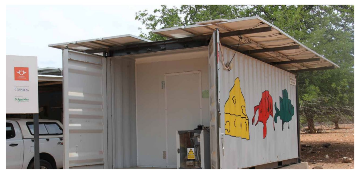
2.1. Gwakwani Case
2.2. Mathematical Modelling
- 1.
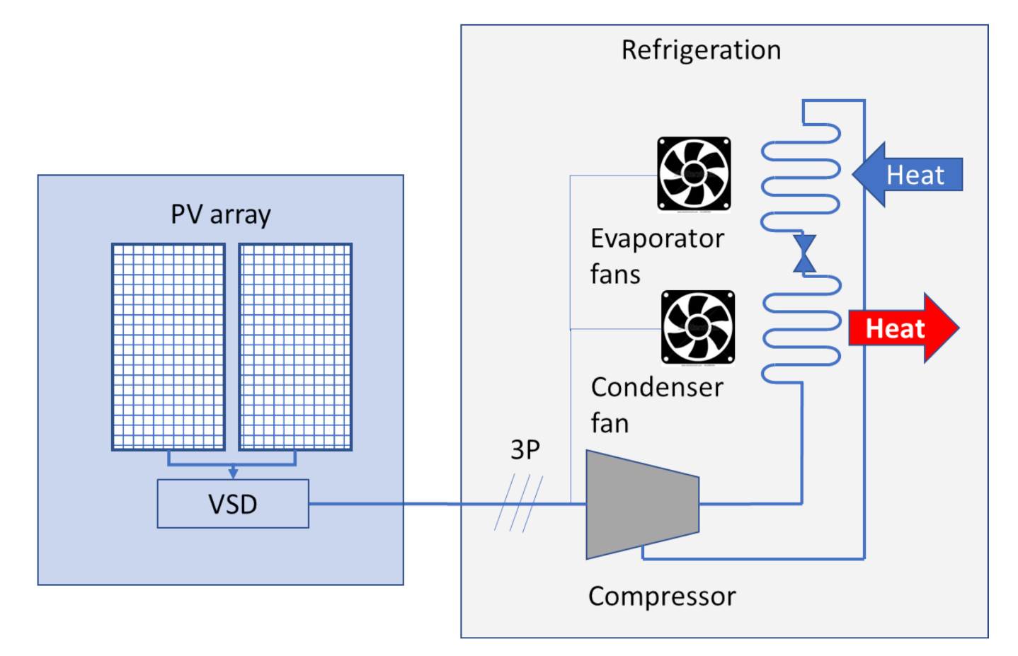
- Electrical system architecture;
- 2.
- Cold storage geographical orientation;
- 3.
- PV array mounting and tilt;
- 4.
- Insolation material thickness;
- 5.
- PV array sizing;
- 6.
- Cold storage temperature dynamic behavior.
3. Design Considerations
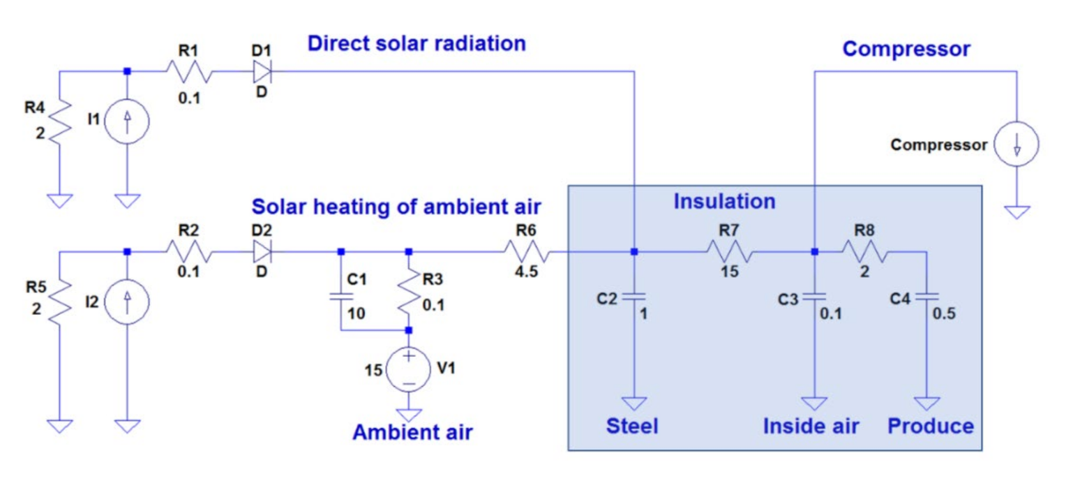
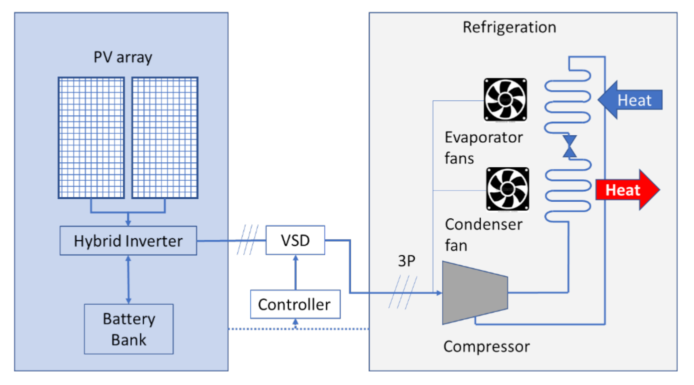
3.1. Electrical System Architecture
3.1.1. Advantages
3.1.2. Disadvantages
3.1.3. Advantages
3.1.4. Disadvantages
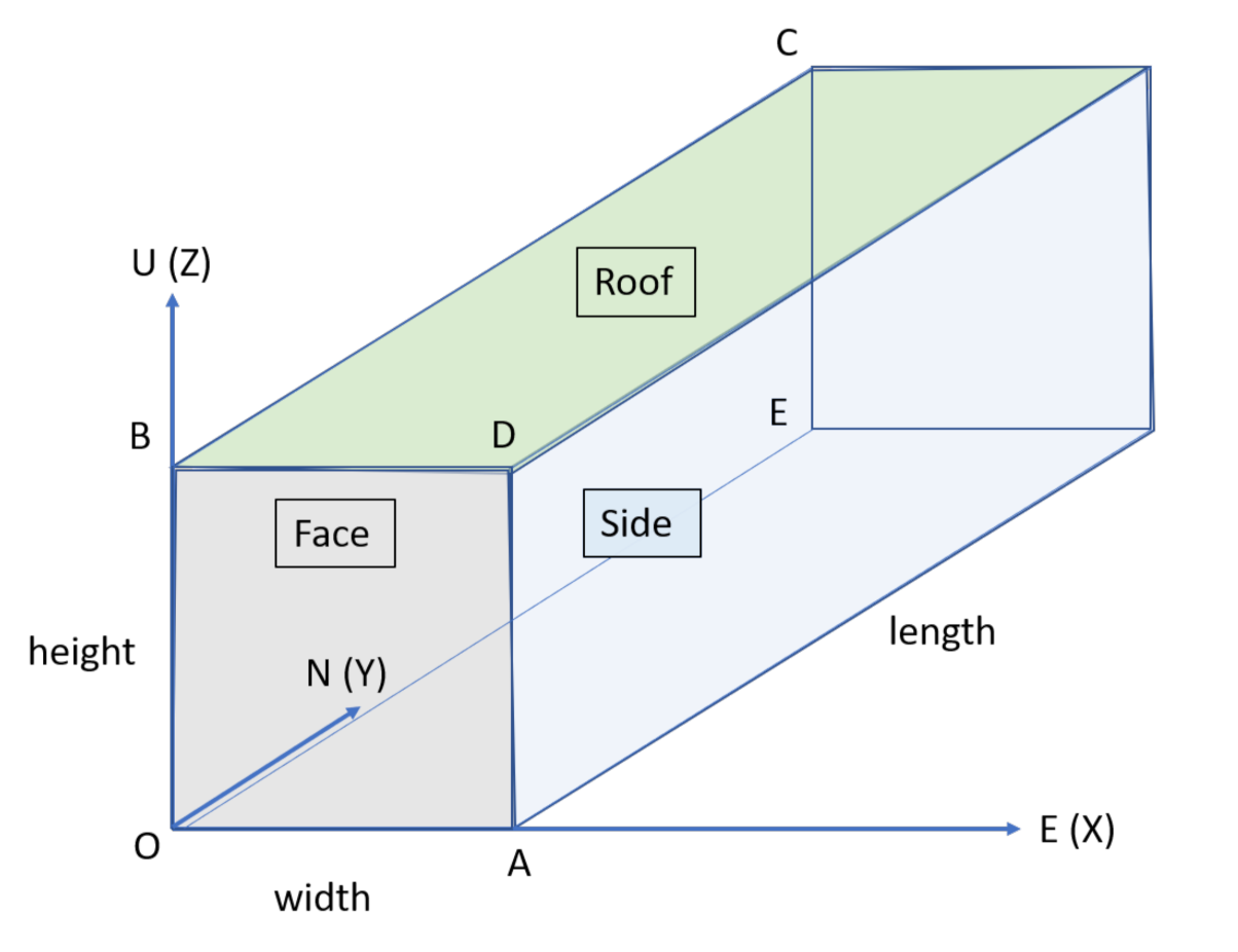
3.2. Cold Storage Container Placement Orientation
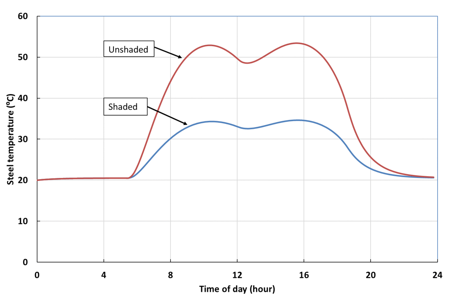
3.3. Solar Panel Mounting Consideration
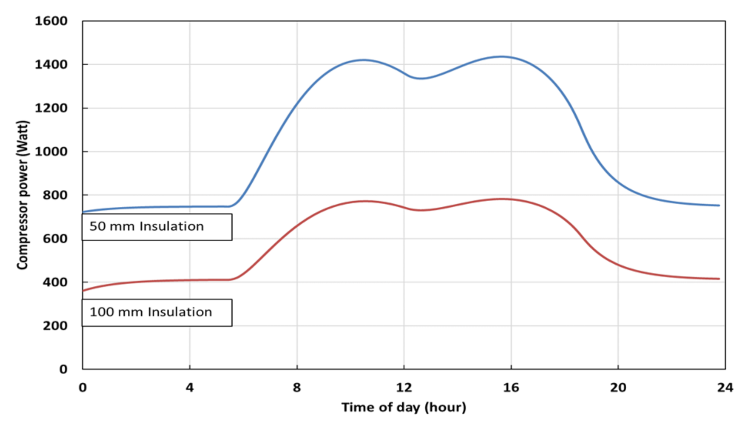
3.4. Insolation Material Thickness Consideration
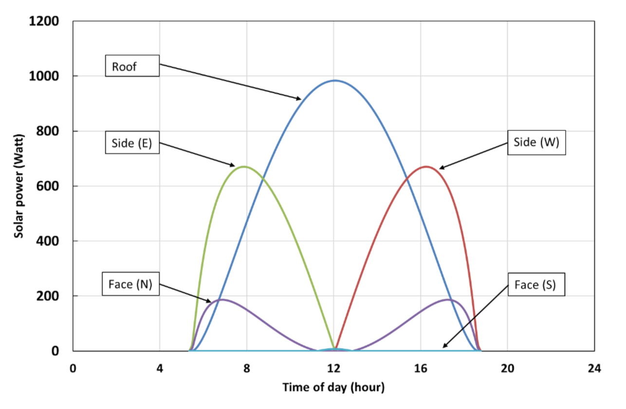
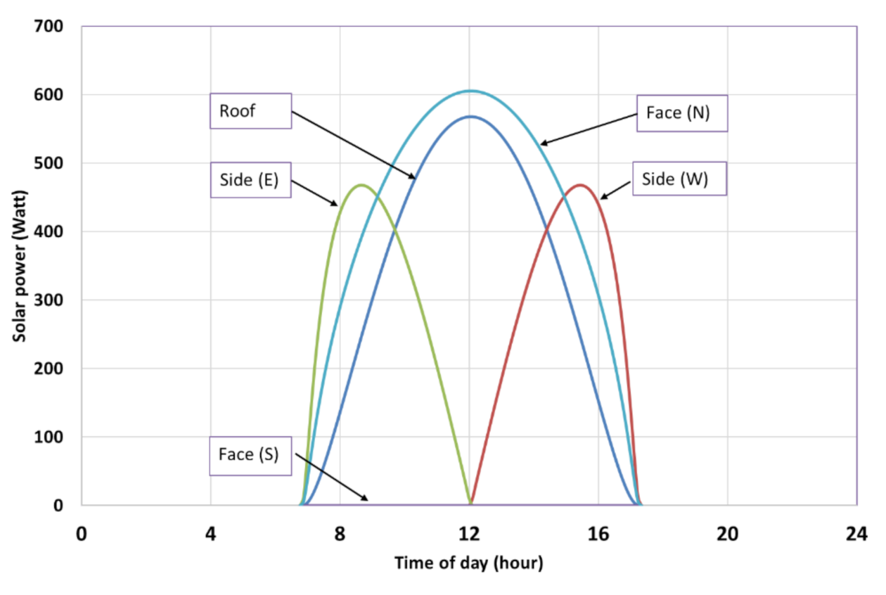
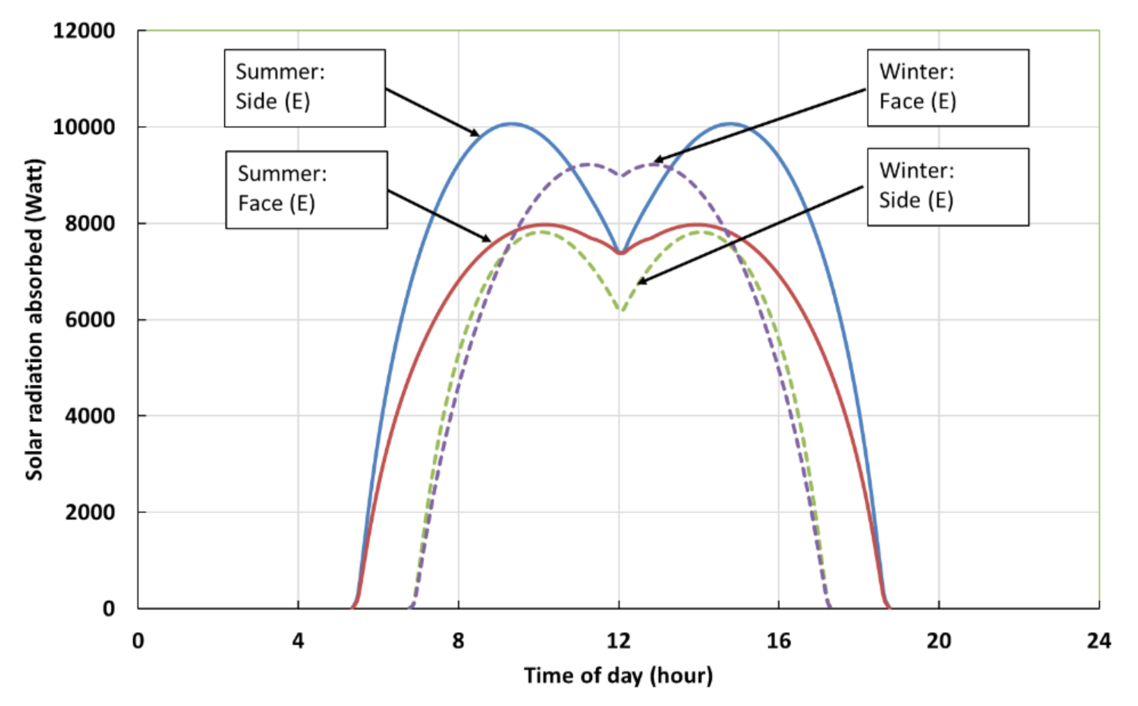
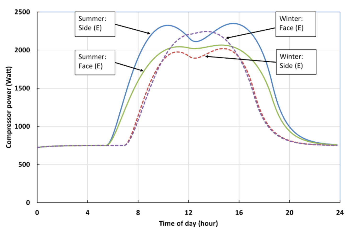
3.5. Geographical Orientation Consideration
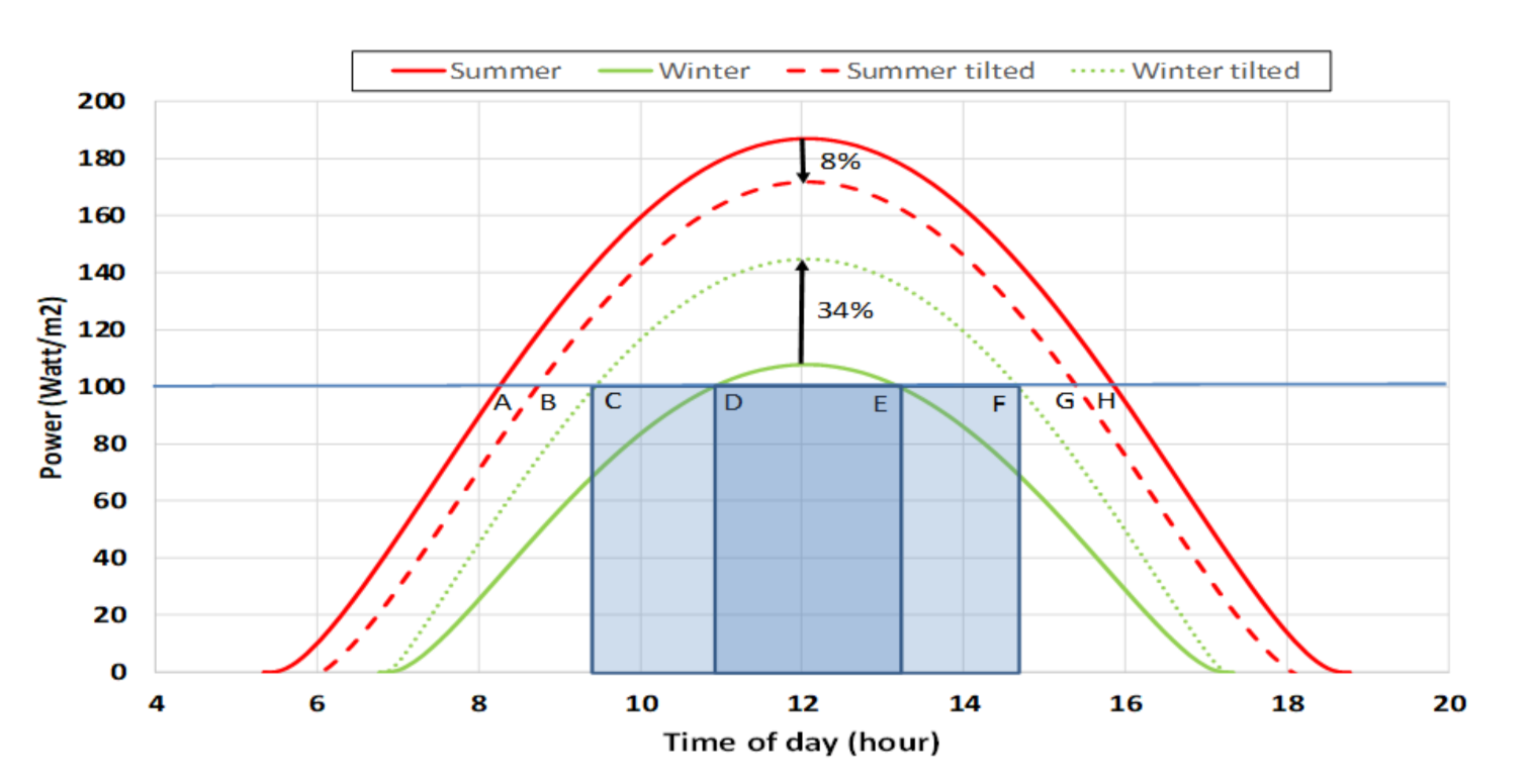
3.6. Photovoltaic Panels Tilt Consideration
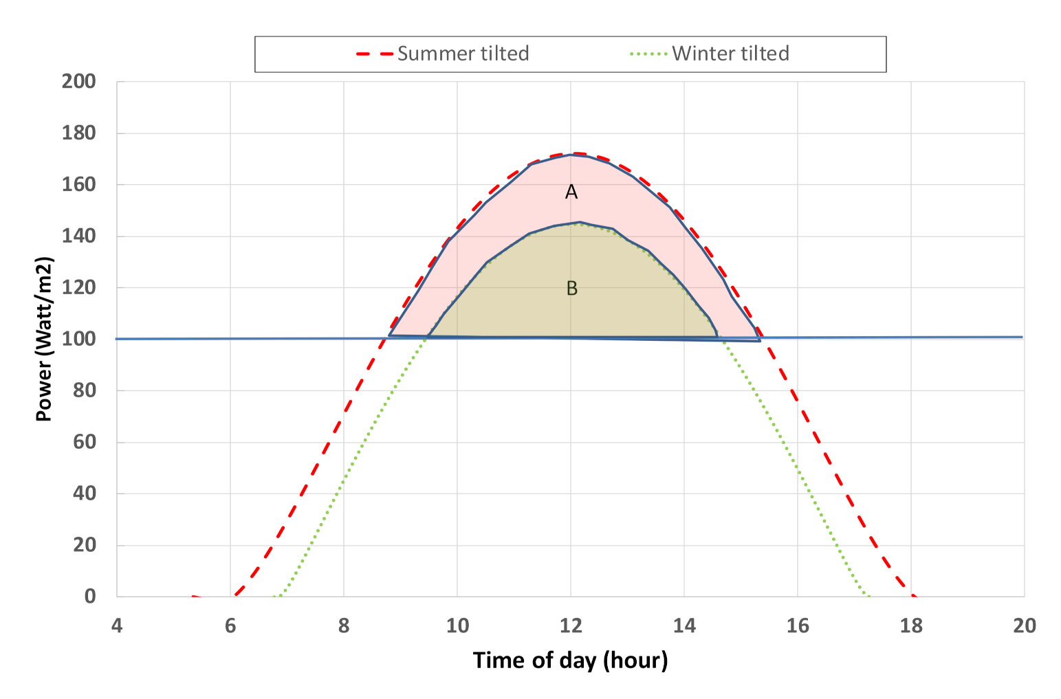
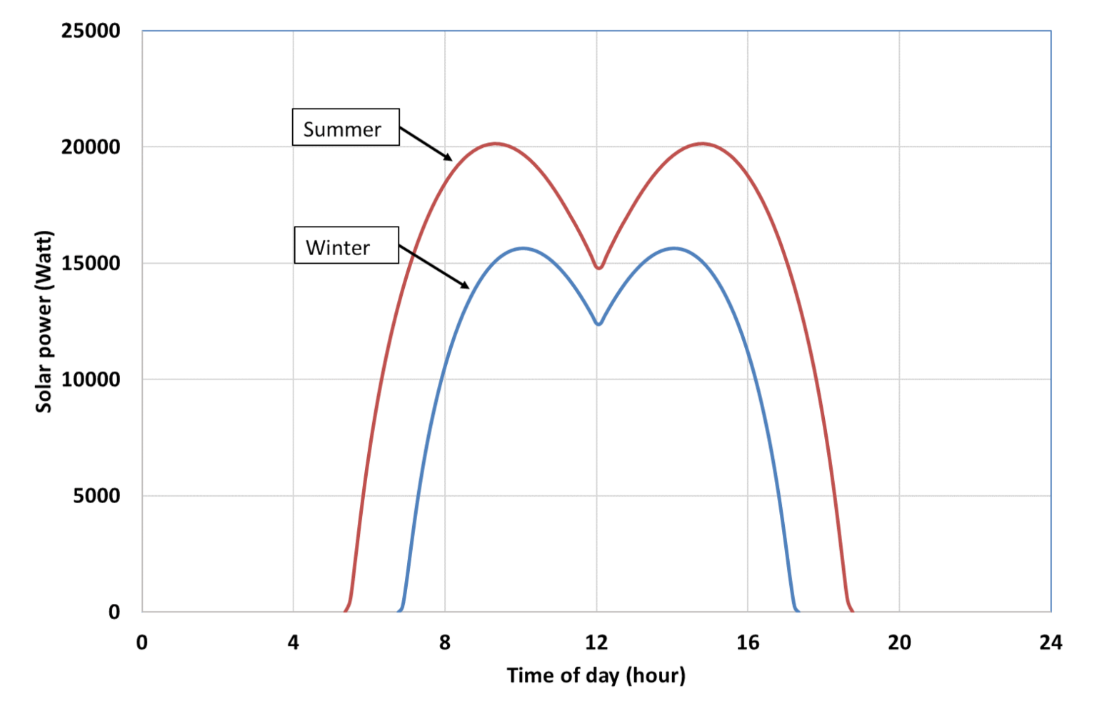
3.7. Excess Energy Collected during the Day for utilization at Night
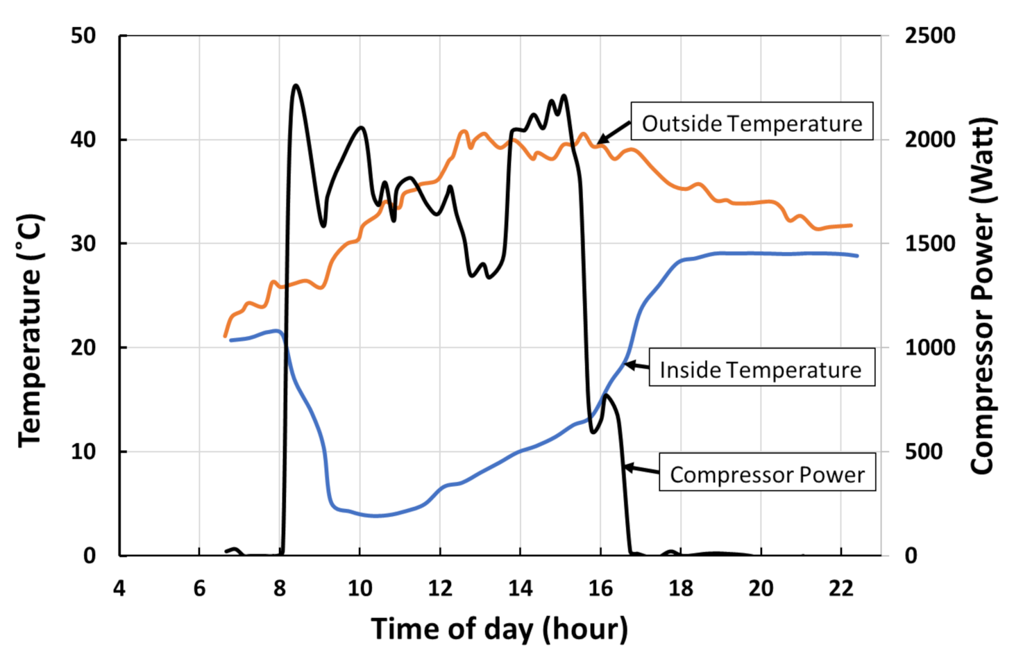
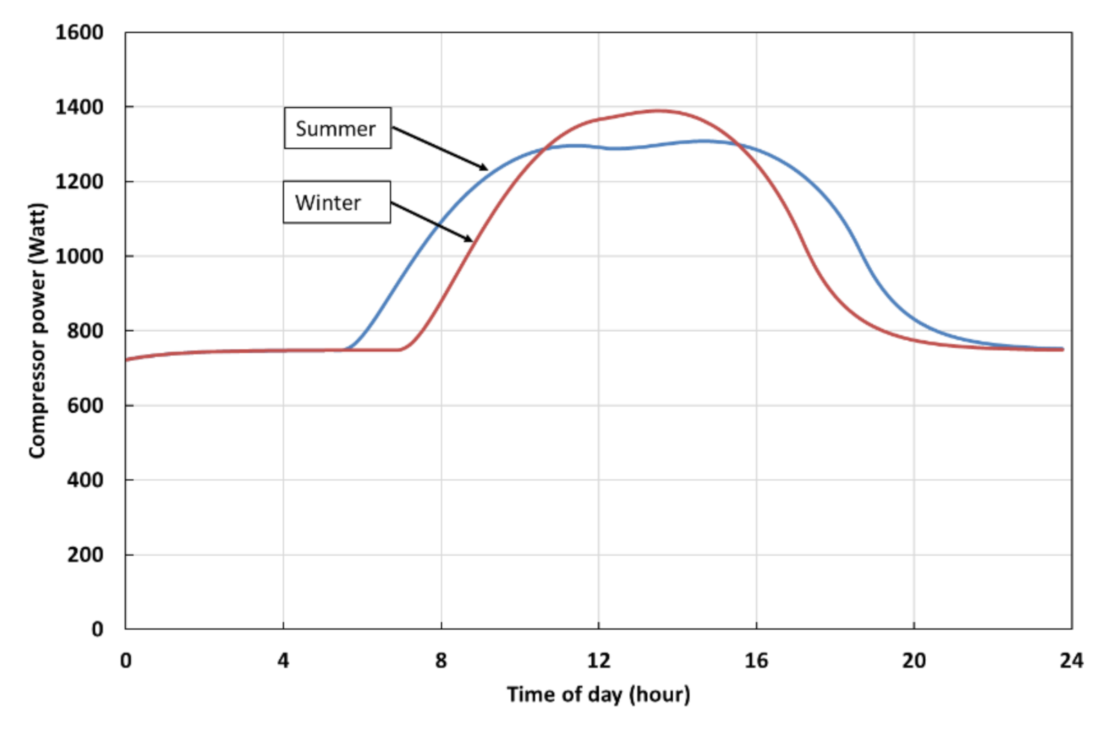
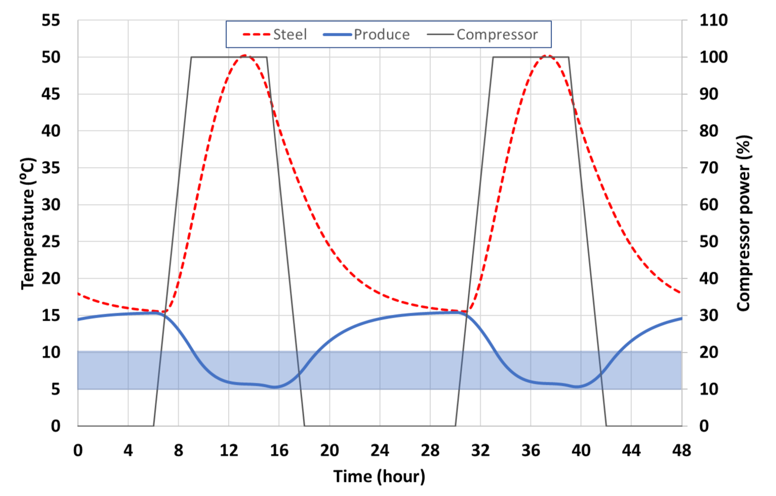
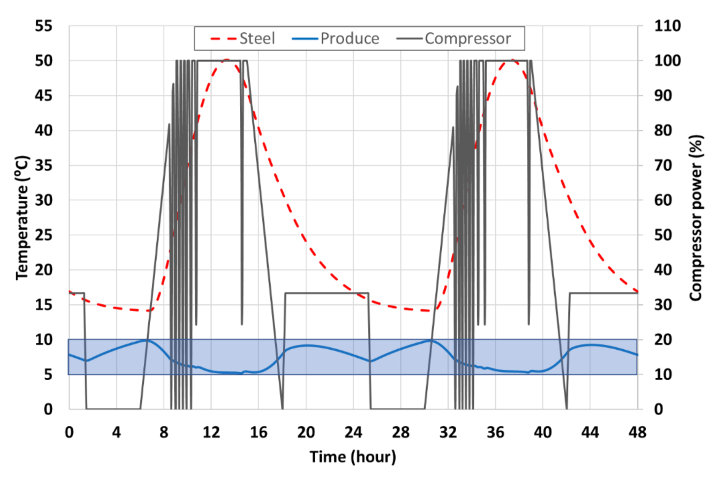
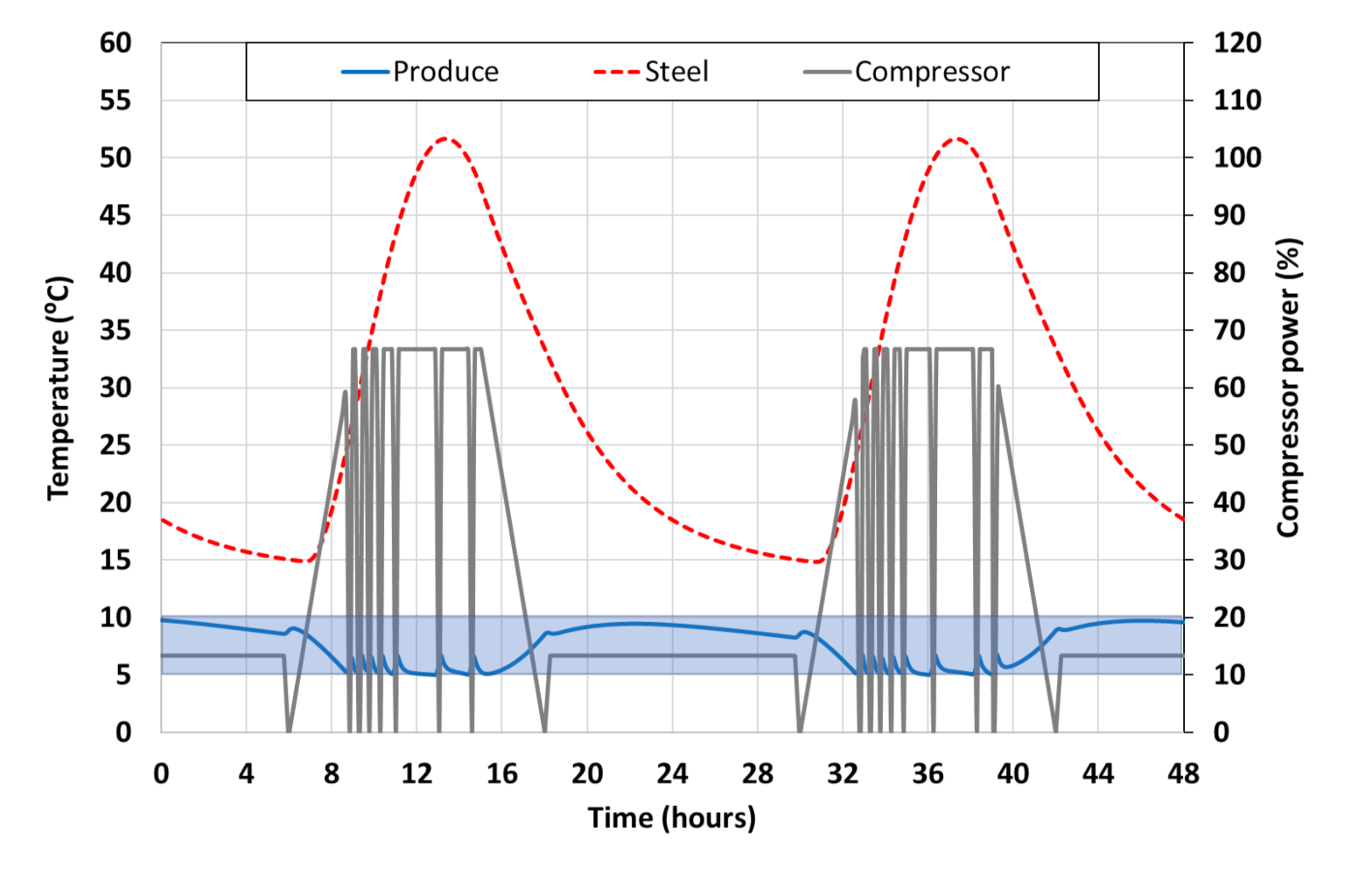
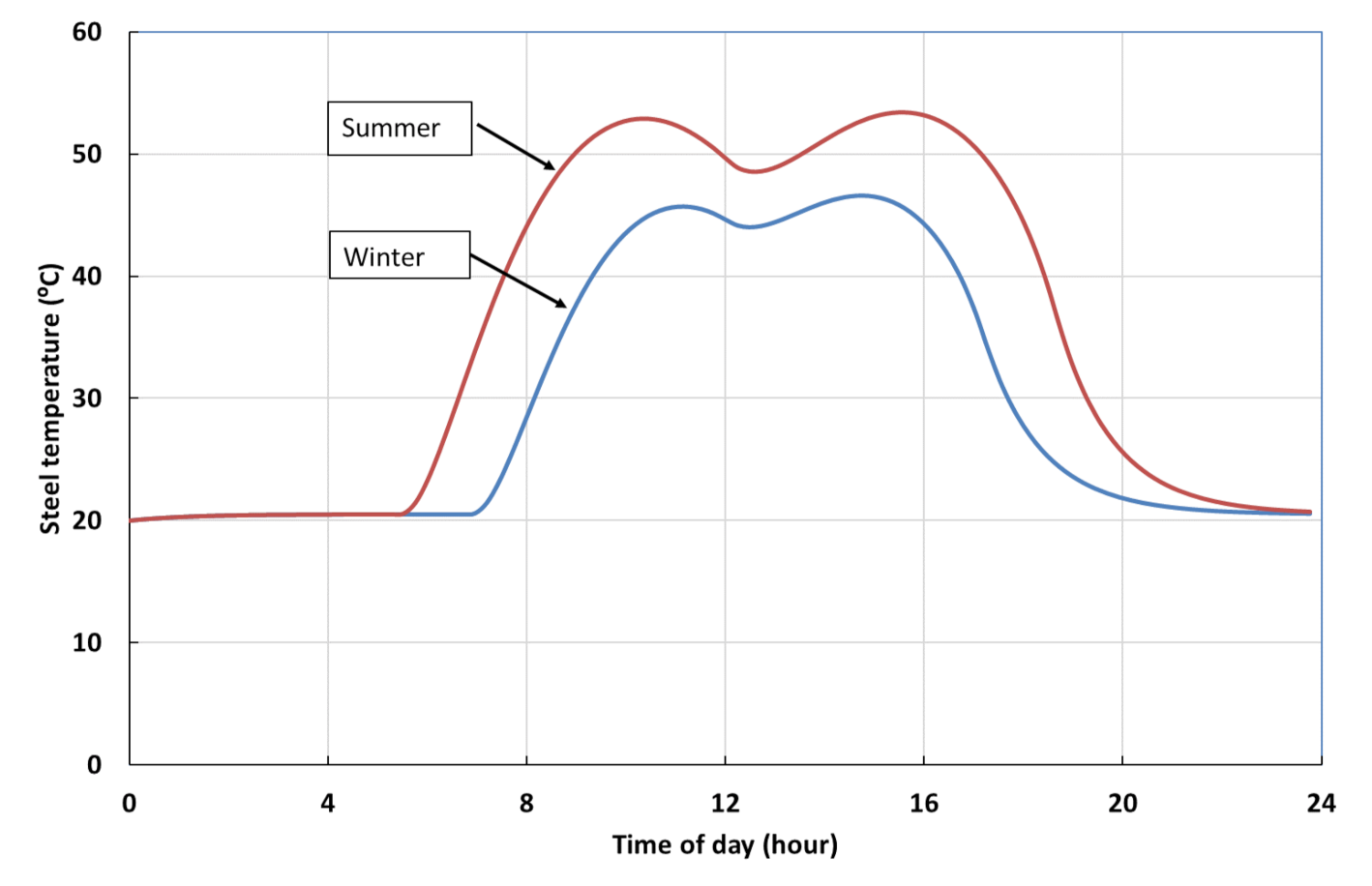
3.8. Dynamic Behavior
4. Discussion
Author Contributions
Funding
Institutional Review Board Statement
Informed Consent Statement
Data Availability Statement
Acknowledgments
Conflicts of Interest
References
- Davis, M. Rural household energy consumption: The effects of access to electricity—Evidence from South Africa. Energy Policy 1998, 26, 207–217. [Google Scholar] [CrossRef]
- De, R.K.; Ganguly, A. Modeling and analysis of a solar thermal-photovoltaic-hydrogen-based hybrid power system for running a standalone cold storage. J. Clean. Prod. 2021, 293, 126202. [Google Scholar] [CrossRef]
- Itote, F.; Irungu, G.; Saulo, M. Power quality assessment of renewable energy sources integration on mv networks. Int. J. Sci. Technol. Res. 2019, 8, 1972–1979. [Google Scholar]
- Mandelli, S.; Barbieri, J.; Mereu, R.; Colombo, E. Off-gri4d systems for rural electrification in developing countries: Definitions, classification and a comprehensive literature review. Renew. Sustain. Energy Rev. 2016, 58, 1621–1646. [Google Scholar] [CrossRef]
- World Bank. World Development Indicators 2000; World Bank: Washington, DC, USA, 2000. [Google Scholar]
- Aktacir, M.A. Experimental study of a multi-purpose PV-refrigerator system. Int. J. Phys. Sci. 2011, 6, 746–757. [Google Scholar] [CrossRef]
- Molero-Villar, N.; Cejudo-López, J.M.; Domínguez-Muñoz, F.; Carrillo-Andrés, A. A comparison of solar absorption system configurations. Sol. Energy 2012, 86, 242–252. [Google Scholar] [CrossRef]
- Said, S.A.M.; El-Shaarawi, M.A.I.; Siddiqui, M.U. Alternative designs for a 24-h operating solar-powered absorption refrigeration technology. Int. J. Refrig. 2012, 35, 1967–1977. [Google Scholar] [CrossRef]
- Basu, D.N.; Ganguly, A. Solar thermal-photovoltaic powered potato cold storage—Conceptual design and performance analyses. Appl. Energy 2016, 165, 308–317. [Google Scholar] [CrossRef]
- Luerssen, C.; Gandhi, O.; Reindl, T.; Sekhar, C.; Cheong, D. Life cycle cost analysis (LCCA) of PV-powered cooling systems with thermal energy and battery storage for off-grid applications. Appl. Energy 2020, 273, 115145. [Google Scholar] [CrossRef]
- Rech, S.; Finco, E.; Lazzaretto, A. A multicriteria approach to choose the best renewable refrigeration system for food preservation. Renew. Energy 2020, 154, 368–384. [Google Scholar] [CrossRef]
- Zheng, L.; Zhang, W.; Liang, F. A review about phase change material cold storage system applied to solarpowered air-conditioning system. Adv. Mech. Eng. 2017, 9, 1–20. [Google Scholar] [CrossRef]
- Wang, X.; Dennis, M. Influencing factors on the energy saving performance of battery storage and phase change cold storage in a PV cooling system. Energy Build. 2015, 107, 84–92. [Google Scholar] [CrossRef]
- Radhi, M.M.; Johain, J.F.; Khalifa, A.-H.N. Experimental study of cold storage packed domestic refrigerator with solar powered variable speed compressor. IOP Conf. Ser. Mater. Sci. Eng. 2021, 1105, 012060. [Google Scholar] [CrossRef]
- Ikram, H.; Javed, A.; Mehmood, M.; Shah, M.; Ali, M.; Waqas, A. Techno-economic evaluation of a solar PV integrated refrigeration system for a cold storage facility. Sustain. Energy Technol. Assess. 2021, 44, 101063. [Google Scholar] [CrossRef]
- Tizzaoui, M.; Soualmi, H.; Allaoui, M.; Mansouri, A.; Saadi, Z.; Menacer, D.; Chadli, S. Solar PV power driven cold room storage for Saharan rural area. E3S Web Conf. 2020, 152, 01004. [Google Scholar] [CrossRef]
- Iqbal, A.; Chowdhury, S.; Srijan, M.H.; Faruq, M.U.; Rahman, A.; Azad, A. Compressor Freezer with a Swapped DC. 2018 IEEE Symp. Comput. Appl. Ind. Electron. 2018, 65–70. [Google Scholar]
- Gupta, B.L.; Bhatnagar, M.; Mathur, J. Optimum sizing of PV panel, battery capacity and insulation thickness for a photovoltaic operated domestic refrigerator. Sustain. Energy Technol. Assess. 2014, 7, 55–67. [Google Scholar] [CrossRef]
- Honsberg, C.; Bowden, S. PV Eductaion. Available online: www.pveducation.org (accessed on 15 March 2022).
- Fayazbakhsh, M.A.; Bagheri, F.; Bahrami, M. A resistance-capacitance model for real-time calculation of cooling load in HVAC-R systems. J. Therm. Sci. Eng. Appl. 2015, 7, 041008. [Google Scholar] [CrossRef]


| Parameter | Value |
|---|---|
| Shipping container | Standard 6 m steel shipping container |
| Cold storage volume | 26 m3 |
| Equipment bay volume | 6 m3 |
| Refrigeration compressor power rating | 2.2 kW, 380 VAC |
| Refrigerant | R-22 |
| Solar panels | 14 × 325 W |
| Solar panel Vmppt | 37.2 V |
| Nominal solar energy yield per day | 27 300 Wh |
| Solar panel tilt | Flat 0° |
| Insulation material | Extruded polystyrene R = 0.024 W/m2 °C |
| Insulation material thickness | 50 mm |
| Geographic location | 22°34′19.3″ S 30°48′16.0″ E |
| Solar variable speed drive | Schneider Electric Altivar 312 Solar ATV312HU55N4412 |
| Simulation Parameter | Value |
|---|---|
| Maximum solar radiation on atmosphere surface | 1361 W/m2 |
| Solar radiation computations | PV education [19] |
| Geographical location | 23.5° S, 30° E |
| Time zone | GMT + 2 h |
| Container outside height | 2.6 m |
| Container outside length | 6.06 m |
| Container outside width | 2.44 m |
| Container steel wall surface solar heat absorption factor | 0.2 |
| Container steel mass | 2230 kg |
| Specific heat capacity of steel | 500 J/kg°K |
| Thermal conductivity of insulation material | 0.033 W/m°K |
| Nominal thickness of insulation material | 50 mm |
| Stefan’s constant, σ | 5.667 × 10⁻⁸ W/m2/K4 |
| Emissivity of container steel wall, ε | 0.5 |
| Ambient sky temperature TSky | 297° K (20 °C) |
| Electrical Circuit Model Parameters | |
| R1, R2, R3 | 0.1 Ohm |
| R4, R5, R8 | 2 Ohm |
| R6 | 4.5 Ohm |
| R7 | 15 Ohm |
| C1 | 10 F |
| C2 | 1 F |
| C3 | 0.1 F |
| C4 | 0.5 F |
| PV Array Tilt Angle (deg) | Mid-Summer (W/m2) | Mid-Winter (W/m2) |
|---|---|---|
| 0 | 187 | 108 |
| 10 | 184 | 126 |
| 20 | 176 | 141 |
| 30 | 163 | 150 |
| 35 | 154 | 154 |
| 40 | 144 | 157 |
| 50 | 121 | 157 |
| 60 | 94 | 153 |
Publisher’s Note: MDPI stays neutral with regard to jurisdictional claims in published maps and institutional affiliations. |
© 2022 by the authors. Licensee MDPI, Basel, Switzerland. This article is an open access article distributed under the terms and conditions of the Creative Commons Attribution (CC BY) license (https://creativecommons.org/licenses/by/4.0/).
Share and Cite
Meyer, J.; von Solms, S. Design Considerations for Reducing Battery Storage in Off-Grid, Stand-Alone, Photovoltaic-Powered Cold Storage in Rural Applications. Energies 2022, 15, 3468. https://doi.org/10.3390/en15093468
Meyer J, von Solms S. Design Considerations for Reducing Battery Storage in Off-Grid, Stand-Alone, Photovoltaic-Powered Cold Storage in Rural Applications. Energies. 2022; 15(9):3468. https://doi.org/10.3390/en15093468
Chicago/Turabian StyleMeyer, Johan, and Sune von Solms. 2022. "Design Considerations for Reducing Battery Storage in Off-Grid, Stand-Alone, Photovoltaic-Powered Cold Storage in Rural Applications" Energies 15, no. 9: 3468. https://doi.org/10.3390/en15093468
APA StyleMeyer, J., & von Solms, S. (2022). Design Considerations for Reducing Battery Storage in Off-Grid, Stand-Alone, Photovoltaic-Powered Cold Storage in Rural Applications. Energies, 15(9), 3468. https://doi.org/10.3390/en15093468