Article

Dynamic Performance Analysis by Laboratory Tests of a Sustainable Prefabricated Composite Structural Wall System

by
Evangelia Georgantzia
1,2,
Themistoklis Nikolaidis
1,*,
Konstantinos Katakalos
3,
Katerina Tsikaloudaki
4 and
Theodoros Iliadis
5
1
Department of Civil Engineering, Institute of Metal Structures, Aristotle University of Thessaloniki, 54124 Thessaloniki, Greece
2
School of Civil Engineering and Built Environment, Liverpool John Moores University, Merseyside L3 3AF, UK
3
Laboratory for Strength of Materials and Structures, Department of Civil Engineering, Aristotle University of Thessaloniki, 54124 Thessaloniki, Greece
4
Laboratory of Building Construction & Building Physics, Department of Civil Engineering, Aristotle University of Thessaloniki, 54124 Thessaloniki, Greece
5
Iliadis Prefabricated Constructions, Prefabricated Construction Industry, 57001 Thessaloniki, Greece
*
Author to whom correspondence should be addressed.
Energies 2022, 15(9), 3458; https://doi.org/10.3390/en15093458
Submission received: 14 April 2022 / Revised: 1 May 2022 / Accepted: 5 May 2022 / Published: 9 May 2022
(This article belongs to the Special Issue Innovative Building Envelope Materials and Sustainable Constructions)

Abstract

:
In recent decades, steel frames infilled with precast load-bearing walls have been successfully employed as lateral load-resisting structural systems in high-rise buildings. This is due to their structural efficiency as outer and major inner facades and to the higher construction speed of the building. This paper presents a detailed experimental investigation of a sustainable, prefabricated, composite structural wall system, using a representative test model named the Precast Concrete Steel Panel-Infilled Steel Frame (PCSP-ISF) in full-scale dimensions and subjected to in-plane cyclic loading. A series of experiments was conducted on critical structural specimens, including three-point bending, concentric axial compression, and diagonal compression, together with additional cycling loading tests on steel connection joint specimens, with the aim of validating the reliability and the structural response of the connections. The resulting test data and the observed failure mechanisms are discussed carefully to optimise the sustainable structural performance of the system. A theoretical approach for the evaluation of the shear capacity of the total frame system is also discussed to expand the experimental results for several numerical and experimental research cases. The failure mechanism of this module was formed by a combination of developed plastic hinges on the steel joints and diagonal cracks on the concrete panel. The obtained hysteretic behavior of the system at a parameter with major impact is mainly analysed and discussed. The outcomes indicate a satisfactory and sustainable seismic performance of the PCSP-ISF model, indicating that it can be a very promising lateral load-resisting system for earthquake-prone regions.

1. Introduction

According to the report on the state of the art by the Federation Internationale du Beton [1], over the last 30 years 75% of new multi-storey buildings have been constructed using a combination of precast concrete and structural steelwork. The high interest in mixed construction is generated by its efficient employment with modular construction techniques, enabling the faster erection and completion of many different types of buildings compared to the conventional constructional methods. Steel and concrete modules can be easily manufactured in a preconstruction stage of factory-made components with an established quality in a low-cost environment and transported and assembled on-site, using suitable connections to assure structural continuity. This cost- and time-effective technology has experienced significant advances in recent years in terms of its fabrication process and assemblage techniques, owing to the higher quality of the final output, as well as a further decrease in the total construction cost.
Nowadays, steel frames infilled with precast load-bearing walls are widely used in steel and composite structures. Thus, a considerable number of experimental studies on precast load-bearing wall panels, both individually and engaged in steel frames, have been presented, with the aim of achieving higher structural efficiency. Holden et al. [2] examined the seismic response of precast conventionally reinforced and precast partially prestressed concrete walls under quasi-static reverse cyclic loading. The comparisons denoted that the former system enabled more energy dissipation but underwent important residual deformations upon unloading. Benayoune et al. [3] experimentally determined the ultimate strength of precast reinforced composite sandwich panels against axial loading. A semi-empirical expression for the ultimate capacity was also proposed, providing reliable but slightly conservative predictions. Furthermore, Hamid and Mander [4] performed full-scale cyclic tests on multi-panel precast concrete hollow core walls, implementing up to ±4% drift amplitude, and found that they were suitable for the construction of single-storey warehouses. Moreover, Pavese and Bournas [5] investigated the seismic performance of prefabricated reinforced concrete sandwich panels by forming a double-storey, full-scale H-shaped structure under combined horizontal and vertical loading. The experimental outcomes denoted satisfactory seismic behaviour with a ductile failure mode. Kabir et al. [6] conducted quasi-static cycling loading tests on bending steel frames infilled with wall panels. They pointed out that strengthening the existing steel frame buildings with wall panels could significantly enhance the lateral stiffness and strength. Hashemi et al. [2] experimentally examined the in-plane seismic behaviour of steel frames infilled with concrete sandwich panels, and Guo and Yuan [7] tested shear walls consisting of steel plate and precast cement-based concrete panels under cyclic loading. The reported results denoted an enhanced buckling strength and shear resistance of the steel plate owing to the presence of the concrete panel. Jiang et al. [8] experimentally assessed the seismic performance of steel- and composite steel-panel wall strengthened steel frames and suggested formulae for the evaluation of the initial lateral stiffness and shear strength of the structural system. Hu et al. [9] proposed a concrete-filled double-skin steel tube frame with a beam-only-connected precast reinforced concrete shear wall system, which sustained an inter-storey drift ratio of more than 4%, indicating its suitability for earthquake-prone regions. Zhu et al. [10] performed tests on concrete-infilled double steel-corrugated plate walls (CDSCWs) under horizontal cyclic loading combined with axial compression. Based on the observed behaviour, they suggested design formulae for estimating the load-bearing capacity of CDSCWs which were found to be accurate and conservative. Furthermore, the seismic performance of a hybrid wall system consisting of a reinforced concrete wall coupled through steel links to steel columns was studied experimentally and numerically in the European research project INNO-HYCO (INNOvative HYbrid and COmposite steel-concrete structural solutions for building in a seismic area) [11]. Huang et al. [12] tested infilled reinforced concrete frames in a large scale and suggested that their design should be based on the “strong frame-weak infill” concept. According to this concept, the strong frame and the weak infill form a two-line defence system against seismic loading, allowing for a simplified calculation of the initial stiffness and ultimate strength of infilled frame structures. Finally, Amran et al. [13] conducted a systematic review of the design innovation, efficiency, and structural applications of Structural Insulated Panels (SIPs). They concluded that the structural performance of the SIPs is still ambiguous, and thus, more research is needed to consider the various loading conditions, such as axial, cyclic, shear, and flexural loading. The proposed study presents a comprehensive experimental research project on the seismic response of a novel model of a Precast Concrete Steel Panel-Infilled Steel Frame (PCSP-ISF), performed in the Laboratory of Experimental Strength of Materials and Structures at the Aristotle University of Thessaloniki. The Precast Reinforced Concrete Panel (PCSP) is a structural infilled panel attached to the columns of the steel frame through bolted joints, providing access for easy assembly and service. The basic concept of this novel optimal control system is to increase the robustness of the steel frame under seismic action and to reduce the weight of the used structural steel members of the frame. The bolted connections were chosen as they are more suitable for easy precast construction, service, and sustainability. During loading, the PCSP-ISF system develops a resisting mechanism which is complex and directly dependent on its constituent elements, which are the PCSP-ISF composite wall system and the joints bolted to the steel frame of the building. Therefore, in order to obtain a clear perspective of its structural performance, the experimental campaign included tests on specimens of the system components, providing the monotonic and cyclic behaviours under consideration, together with the failure modes for each critical case. Table 1 briefly summarises the separated steps of this experimental campaign. Section 2 describes the main principles and critical issues which were taken into consideration when developing the structural concept of the investigated PCSP-ISF system in this study. Aiming to determine the structural behaviour of the PCSP, Section 3 presents a series of tests of the PCSP specimens under various loading and boundary conditions. Section 3.1, in particular, provides a thorough description of the geometrical details and the construction of the test specimens, whilst Section 3.2 discusses the structural response of the PCSP-1 discretized specimen under a three-point bending configuration. Section 3.3 and Section 3.4 address the structural performance of the PCSP-2 and PCSP-3 discretized specimens, respectively, under concentric axial compression and diagonal compression, respectively. Section 4 analyses the hysteretic behaviour of two characteristic steel bolted joint specimens, which are used for the connection of the external steel frame with the internal PCSP system, with different bolt arrangements. Section 5 evaluates the seismic response of a full-scale PCSP-ISF model subjected to in-plane cyclic loading in terms of the load-displacement response, ductility ratio, and equivalent viscous damping ratio with stiffness degradation. In Section 6, a theoretical approach was utilised to evaluate the shear capacity of the PCSP-ISF, expanding the experimental results for several numerical and experimental research cases. Finally, the conclusions on the structural performance of the system and the continuation of this research in the future are summarised in Section 7.

2. Sustainable Design of the Prefabricated Composite Structural Wall System

Prefabricated buildings consist of factory-made components or units that are transported and assembled on-site to form a complete structure. This building system offers many advantages, such as a significant reduction in cost and time, an improved quality and accuracy in manufacture, an increased speed of installation on-site, and easy dismantling for the reuse of its components. In addition, it also offers a reduction in environmental degradation, an increase in productivity gains, a decrease in labour requirements, and an improvement of the working conditions.
There are many prefabricated building types on the construction market, which are categorized with regard to the main material of their structure, namely wood, reinforced concrete, and steel. In low-rise buildings with up to 2–3 storeys above ground, the most widespread prefabrication type is the steel framework due to the easiness and speediness of its site installation, as well as the adaptability of its design. However, in most prefabricated steel constructions, the wall elements are made of lightweight panels, which are designed primarily to sustain gravity and wind loads, with limited or no seismic consideration and no participation in the structural performance of the building. This leads to the need for bigger and/or more steel structural elements, which increase the total steel weight of the building, and thus, there is the structural cost and the respective environmental impact. In addition, the use of light-weight elements for configuring the building envelope decreases the thermal mass of such building types, creating a negative impact on the control of interior temperature and increasing the possibility of overheating, thermal discomfort, and cooling energy needs during the warm period of the year.
Within this framework and with the objective of overcoming the above-mentioned common shortcomings, the research project SU.PR.I.M. (SUstainable PReconstructed Innovative Module) aimed at the development of an innovative wall module with advanced properties that would satisfy the high requirements for its operation and performance, i.e., bear and deliver safely all the imposed building loads; display advanced energy performance; demonstrate excellent hygrothermal behavior; provide acoustic insulation protection and resistance against fire actions; and minimize its environmental footprint during its life cycle. In the light of this holistic approach and conceptual framework, the innovative wall system that was developed fully advances sustainability in the building sector.
The multifunctional, innovative building element was developed through different studies, starting with the structural one, which is thoroughly presented in this study, and was optimised through hygrothermal, energy, acoustic, and fire performance studies [14].
More specifically, the structural behaviour of steel frames infilled with reinforced concrete walls has been thoroughly investigated by a number of theoretical and experimental works. It was demonstrated that this structural system consists of three lateral resisting mechanisms: (i) the contribution of the external steel frame; (ii) the direct interaction between the steel frame and the compression diagonal strut in the PCSP; and (iii) the interaction between the steel frame members and the respective panel surfaces through friction contact and shear connection by steel bars. In order to define the mechanical properties and the optimal geometrical configuration of the PCSP-ISF system, each one of the foregoing resisting mechanisms was investigated in detail in this research project, using conceptual PCSP-i and steel bolted joint specimens of the system as well as a detailed full-scale representative model of the PCSP-ISF under quasi-static cyclic loading.
The basic concept of this study is to design a sustainable structural model with optimal structural performance formed by a suitable element configuration which defines a clear resisting mechanism against seismic action and allows for a simplified initial stiffness and shear capacity evaluation of the system. The proposed structural system is realised so that the surrounding steel frame resists the overturning moments whilst the PCSP resists the shear force, leading finally to minimal acting moments on the frame members. By this mechanism, the PCSP system could act as a passive resisting system of the frame due to horizontal cyclic loading, whilst constituting an easy, prefabricated, and robust cladding for the building. The objective failure mechanism is set to be yielding of the ductile steel frame, followed by concrete crushing preventing an unsatisfactory brittle behaviour. In this respect, the compression stress field on the precast reinforced concrete should be properly controlled. For this purpose, steel bolted joints across the height of the columns are formed using special steel welded sections and blades which shape an effective area, allowing for force transfer between the steel frame and the PCSP system. In this way, on one hand, there is no need for significant slips between the steel frame and the PCSP system for the formation of an inclined uniform compression stress field, and on the other hand, the gap between the vertical sections of the steel frame and the PCSP system allows the elastic but constrained body motion of the steel columns. Moreover, it was assumed that the formation of the compression diagonal strut could be adequately supported by the steel bolted joints. In order to define an easy precast construction and a simple and fast replacement of the damaged PCSP wall after an earthquake hazard, it was decided that the joint connections were to be bolted. Therefore, the system is referred to as a partially restrained PCSP-ISF. The proposed structural system is expected to present satisfactory performance against in-plane cyclic loading, taking advantage of the stiffness and strength of the undamaged PCSP wall and the steel frame at the initial and the ultimate state, respectively.

3. Experimental Investigations of Precast Reinforced Concrete Panel (PCSP) Specimens

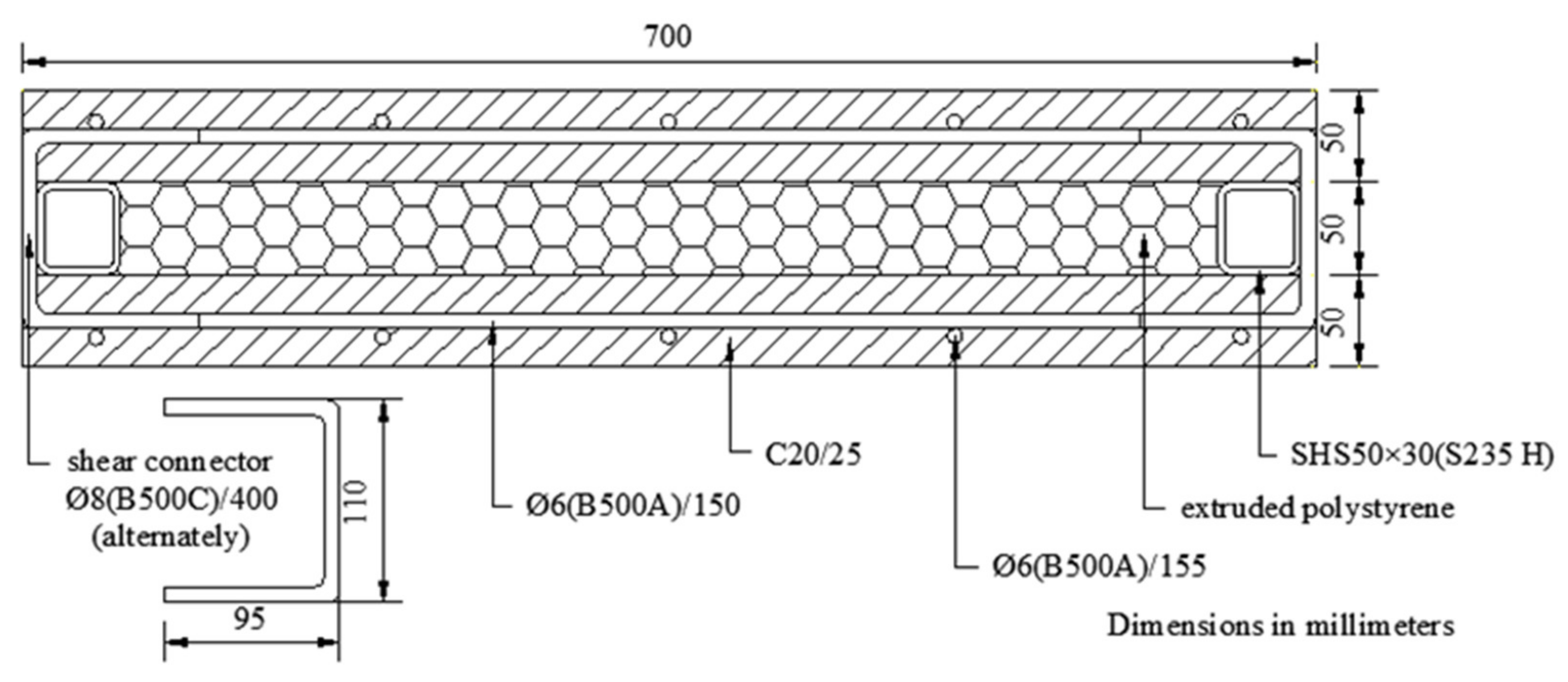
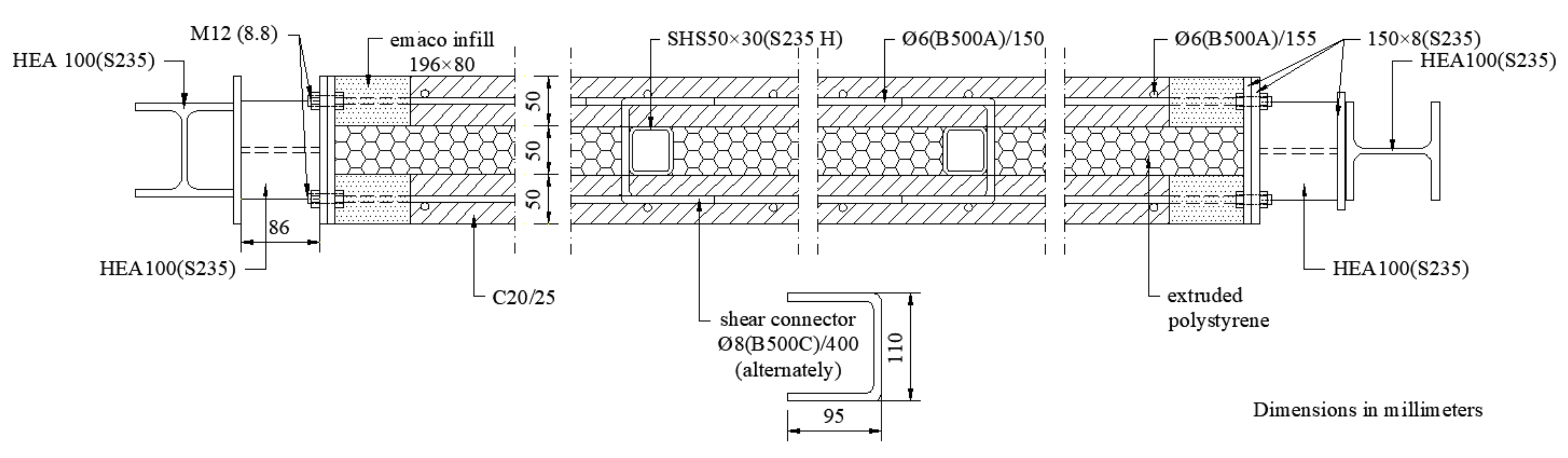
3.1. Geometrical Details and Construction of PCSP-i Test Specimens

In order to minimise the destructive test program in an optimal and sustainable way and to develop a reliable resisting mechanism of the infill prefabricated panel, which works together with the steel frame, a mixed program with the theoretical, numerical, and most appropriate loading test was established in the laboratory. The basic concept of the PCSP identical model specimen under the three-point bending test was to calibrate the final form resulting from several numerical, investigated approaches regarding the flexibility and the out-plane behavior of the wall. Moreover, the same destructive test defined the critical buckling behavior of the cross-section of the specimen [15] in the longitudinal direction (vertical direction of the wall) by converting the ultimate transverse load of the test to an equivalent critical buckling load of the critical, simple, supported model.
The investigated PCSP-1 specimen comprised two 50 mm-thin concrete panels with a width of 700 mm, due to the geometrical limitations of the laboratory equipment. However, this width value is representative and adequate to capture the actual structural response of the PCSP system in out-of-plane bending around a horizontal axis in order to form a safe PCSP-ISF system for a residential building. The two respective concrete panels were reinforced with a steel bar mesh of a 6 mm diameter and a quality of B500A (nominal yield strength of 500 MPa), certified according to [16]. The concrete mesh reinforcement was mounted at about 20 mm from each external surface of the panel and consisted of horizontal and transverse steel bars spaced at 150 mm and 155 mm, respectively. The transverse reinforcement cross-section ratio to the respective surrounding concrete was 0.36%, which is greater than the minimum transverse reinforcement ratio defined in EN 1992-1-1 [17]. The purpose of the aforementioned described net reinforcements in each one of the panel walls is not only to improve the flexural behaviour, the tensile strength, and the beginning of initial cracks due to shrinkage of the concrete, but also to prevent any damage due to the preconstruction and transportation procedure in situ. Ready concrete mix was used for the concrete panels and was made from ordinary Portland cement, medium coarse sand, and coarse aggregate with a maximum size of 10 mm. Space for the insulation plates (in the present study, extruded polystyrene) was formed between the two concrete panels using two 50 × 30 mm steel square hollow sections (SHSs (S235 H)) of 235 MPa nominal yield strength. The two respective concrete panels were attached with full contact to the inside sited vertical SHSs or to the insulating material. Moreover, in order to obtain a composite behaviour of the system, the inside sited vertical SHSs members were connected to either of the respective concrete panels with shear steel bars welded on the SHSs free edges at vertically distributed distances of 400 mm, alternately. The foregoing connecting reinforcement consists of 8 mm-diameter, quality B500C steel bars in accordance with the requirements specified by [18]. In this way, this structural system can develop composite behaviour in out-of-plane bending by shear loading transfer. The geometrical details of the PCSP-1 cross-section are illustrated in Figure 1. The width (700 mm) of the specimens was received, due to the geometrical limitations of the laboratory equipment, by a parametric analysis [15] of a representing unit of the wall system between the steel SHSs sections, using numerical analysis models. By this numerical analysis study using ANSYS software, the buckling performance of the wall system was determined with respect to the maximum and minimum distances, respectively, between the vertical steel stanchions. The used width was taken as the lower limit of the distances between the steel SHSs sections for a passive elastically supporting hybrid system, with the respective 50 mm-thin concrete panels in the longitudinal direction of the wall increasing their buckling resistance. Moreover, the length (H = 3000 mm) of the PCSP-I is equal to the height of a floor of a building, where the clear length between single supports (Hi = 2700 mm) is the clear height of the wall between the horizontal diaphragms.
Upon formwork removal, the specimens were covered with polyethylene sheets and remained in the factory for concrete curing. After 28 days, they were delivered to the laboratory, together with three representative concrete cylindrical samples (150 × 300 mm) of the tested specimens, for material property tests, as defined in [21]. It is noteworthy that no difficulties were encountered during the construction and transportation phases. Each concrete representative sample was tested under axial compression on the same day as each respective performed specimen; their experimental configuration is illustrated in Figure 2. The average measured compressive cylinder strength was 21.3 MPa. The Young’s modulus was calculated using the analytical equations provided by EN 1992-1-1 [17] and was found to be equal to 30,373 MPa.

3.2. Three-Point Bending Test on PCSP-1 Specimen

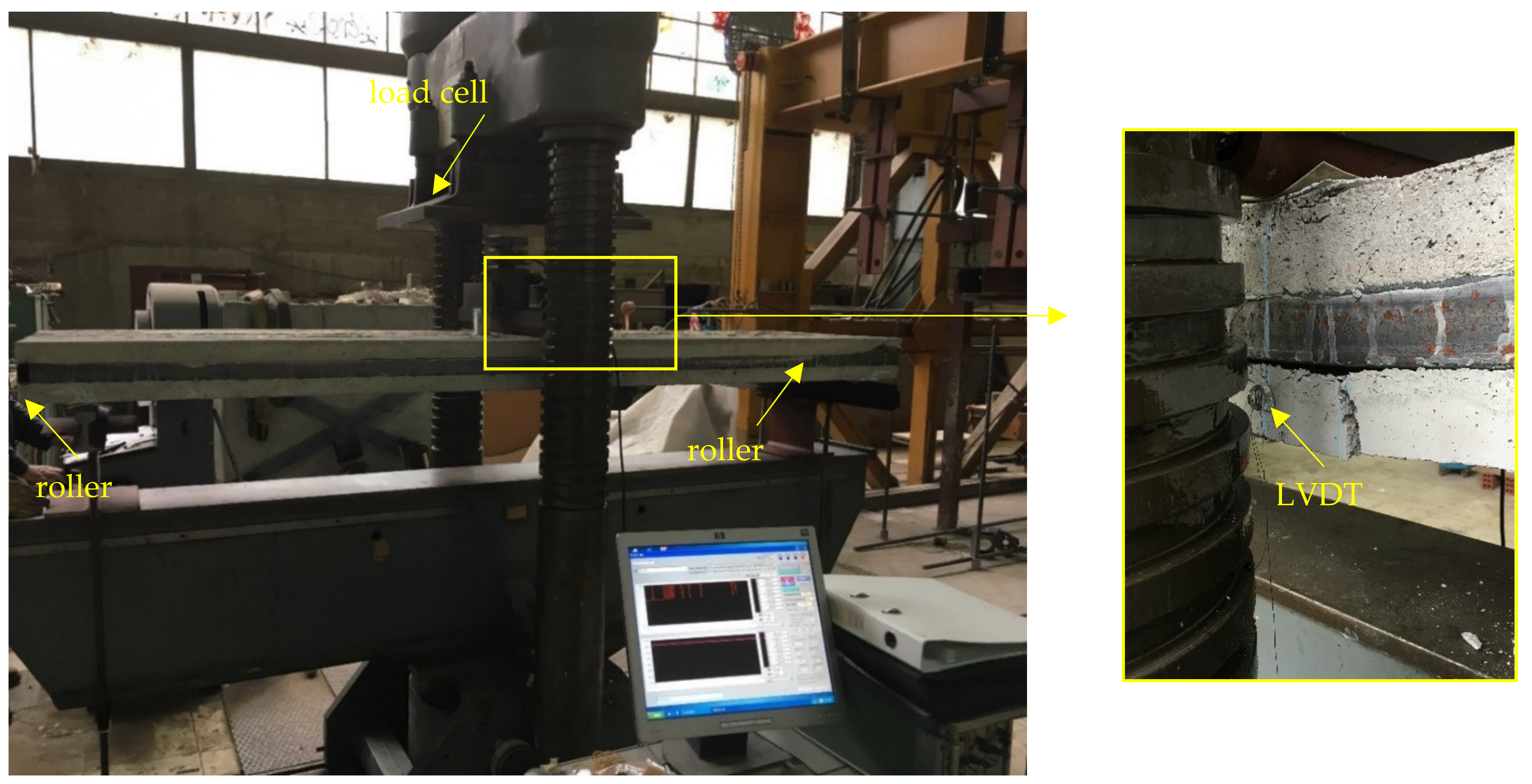
3.2.1. Experimental Setup and Instrumentation of PCSP-1 Specimen

A conceptually named PCSP-1 specimen of 700 × 3000 mm at full scale in height was subjected to a three-point bending test in order to investigate its out-of-plane structural behaviour. The experimental configuration included a single-span specimen with a pinned end and roller supports, according to [22], as illustrated in Figure 3. The edges of the specimen were simply laid on the supports, and the clear distance between them was 2700 mm. The size of the specimens for the concentric axial compression test (700 × 700 mm) PCSP-2a,b was received with the same width (700 mm) as the respective PCSP-I (see Section 3.1) and with a limited height of 700 mm, due to their buckling performance, by taking into account the highest reasonable buckling eigenmode, where the clear vertical length is Hi/4 = (2700 − 2800)/4 = 700 mm.
A reaction frame with a hydraulic jack of 6000 kN maximum load capacity and 300 mm maximum displacement was used to gradually apply increasing monotonic displacement with a constant speed of 0.05 mm/s. The out-of-plane vertical displacements were measured (see Figure 4) using two linear variable displacement transducers (LVDTs) mounted on both edges at the mid-span of the bottom concrete panel (see Figure 3). The applied force was obtained through the load cell of the machine. The behaviour was carefully observed and the developed cracks in each characteristic load step were marked with chalk on the surface. The test was terminated after failure occurred. All measurements were recorded using a data acquisition (DAQ) system at regular intervals with a frequency of 10 Hz.

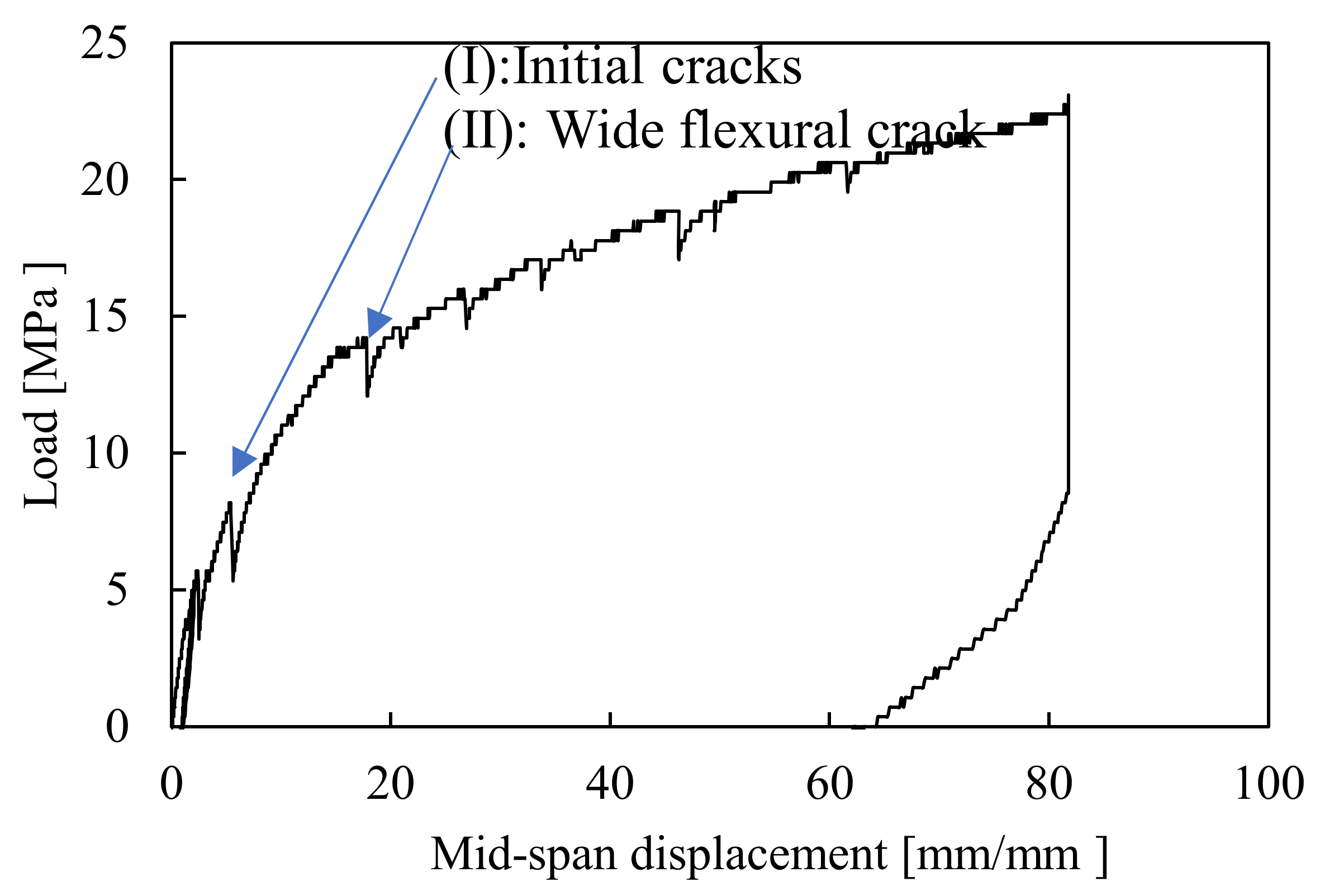
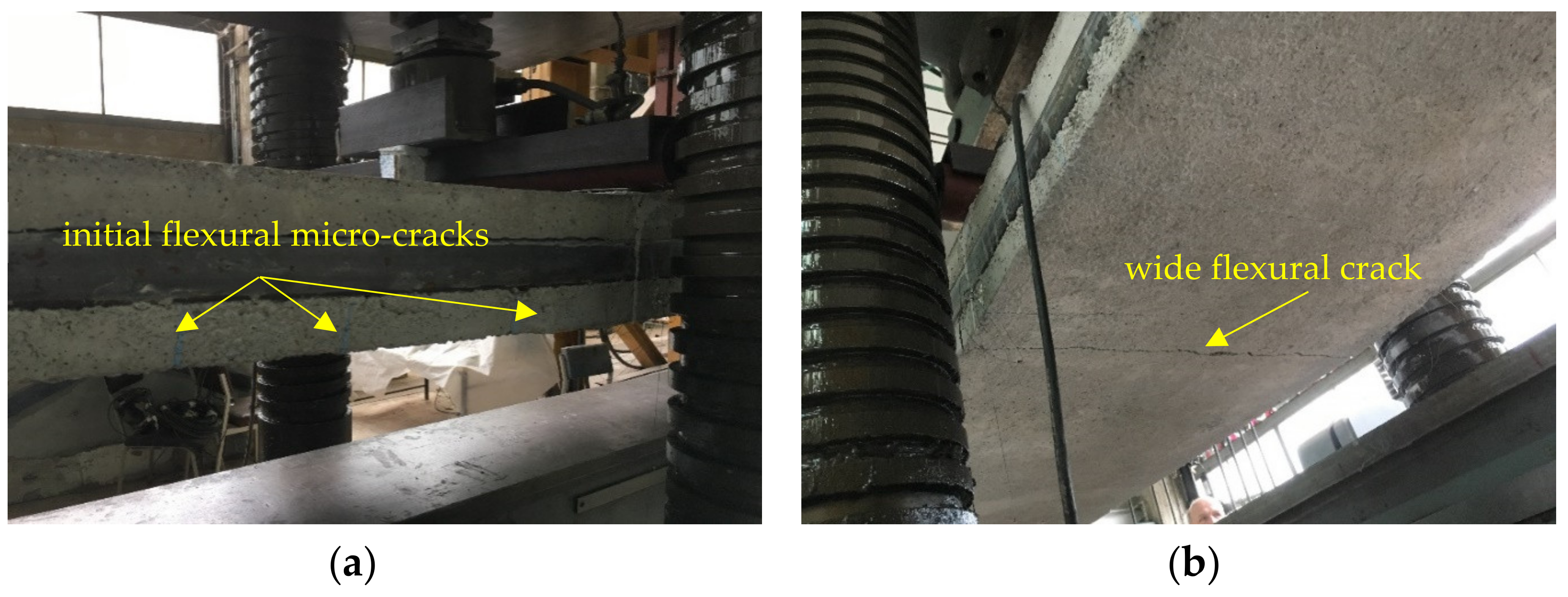
3.2.2. Load-Mid-Span Displacement Response and Failure Mechanism of PCSP-1 Specimen

The obtained load-mid-span displacement curve of the PCSP-1 specimen is presented in Figure 4, where the displacement values are the average measurements recorded from both LVDTs attached to both edges at the mid-span. Initially, the specimen’s behaviour was almost linear up to 10 mm, which corresponded to the 11.0 kN applied loading. At this point, flexural micro-cracks were developed in the tensile concrete panels and around the loading point where the stress concentration was higher (Figure 5a).
Beyond this point and up to 17 mm mid-span displacement and a 13.8 kN corresponding applied loading, the flexural stiffness was considerably decreased, and the concrete cracking was expanded into the mid-span and towards the supports, forming a wide major crack. After maximum load-bearing capacity was achieved, the specimen failed suddenly with a sharp drop in flexural stiffness. The brittle failure resulted in a wide crack along the width at the mid-span of the tensile concrete panel, as shown in Figure 5b. It should be noted that no significant slips were observed in the contact surfaces between the concrete panels and the SHSs, owing to the effective presence of the embedded shear bars against the developed shear forces and the composite behaviour of the system mainly in the linear part of the reaction.

3.3. Concentric Axial Compression Tests on PCSP-2 Specimens

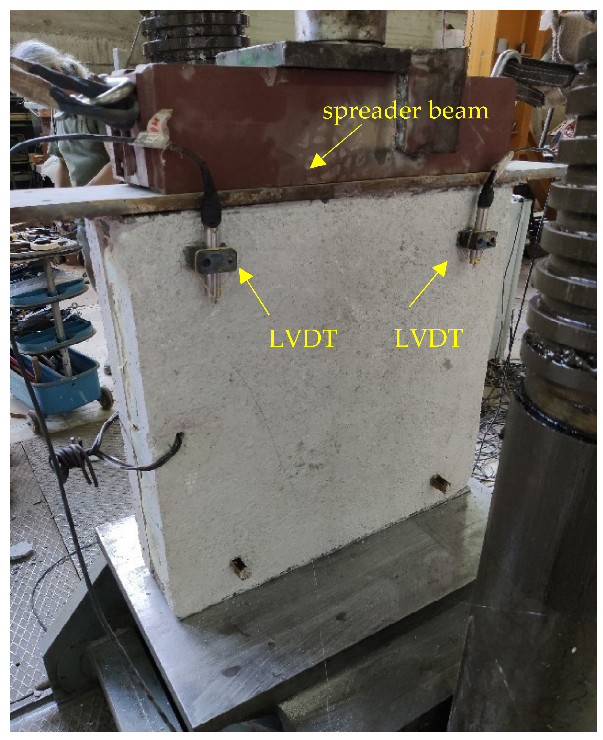
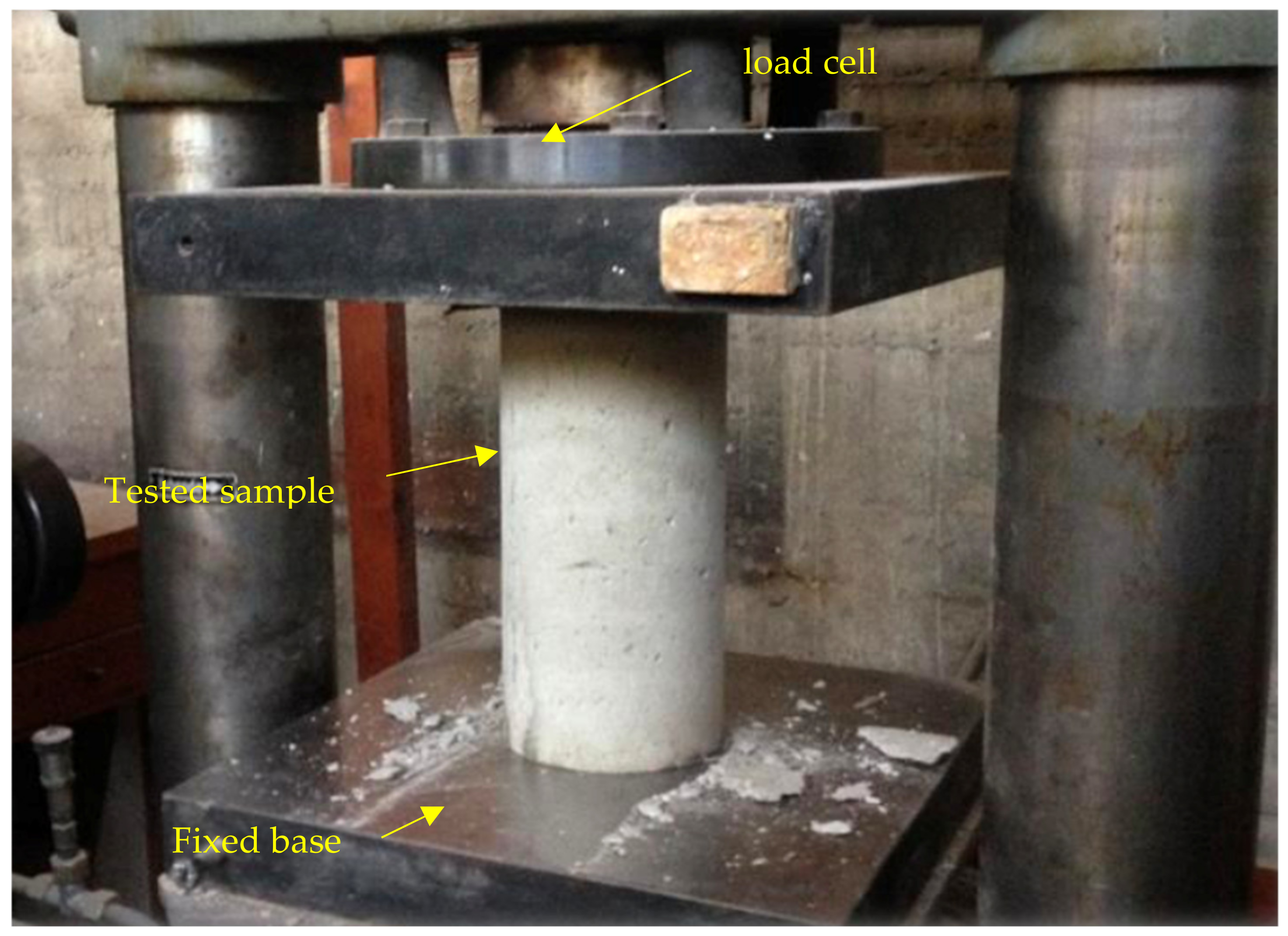
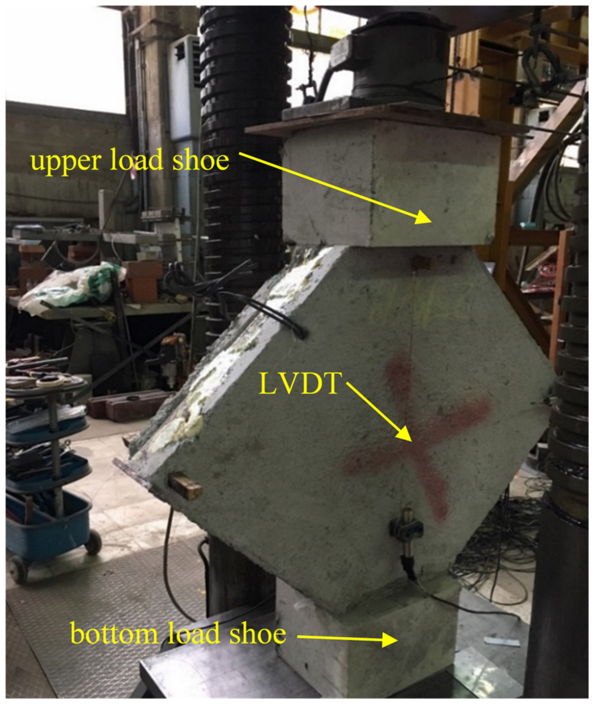
3.3.1. Experimental Setup and Instrumentation of PCSP-2 Specimens

Two 700 × 700 mm specimens, which were identical in component levels and named PCSP-2a,b, were tested under concentric axial compression using pinned- and fixed-end support conditions at the top and bottom edge, respectively. These boundary conditions were chosen because they simulated more accurately the real support conditions of a wall member in a single-storey building. The respective specimens were painted white so that the developed cracks could be clearly observed. The top edge was cast in plaster to assure the contact between the respective surfaces of the SHSs and the concrete panels. The same reaction frame with a hydraulic jack of 6000 kN maximum load capacity and 300 mm maximum displacement, as discussed in Section 3.2, was used here to execute the concentric axial compression tests. The tests were identical and were driven by the displacement control method with a constant speed of 1 mm/min. The uniform load distribution along the width of the specimen was achieved using a steel plate under the highly stiffened compact spreader beam. The axial force was taken using the load cell of the machine, whereas the axial shortening was measured with four LVDTs attached symmetrically to both sides of the specimen, as shown in Figure 6. Upon investigation, the specimen was positioned carefully on the pedestal to avoid any undesirable eccentricity; a small initial load of approximately 1.0 kN was applied to ensure the LVDTs’ recording. The test was terminated when the specimen failed and was unable to sustain more loading. The measurements of the load cell and the LVDTs were recorded using a DAQ system at regular intervals with a frequency of 10 Hz.

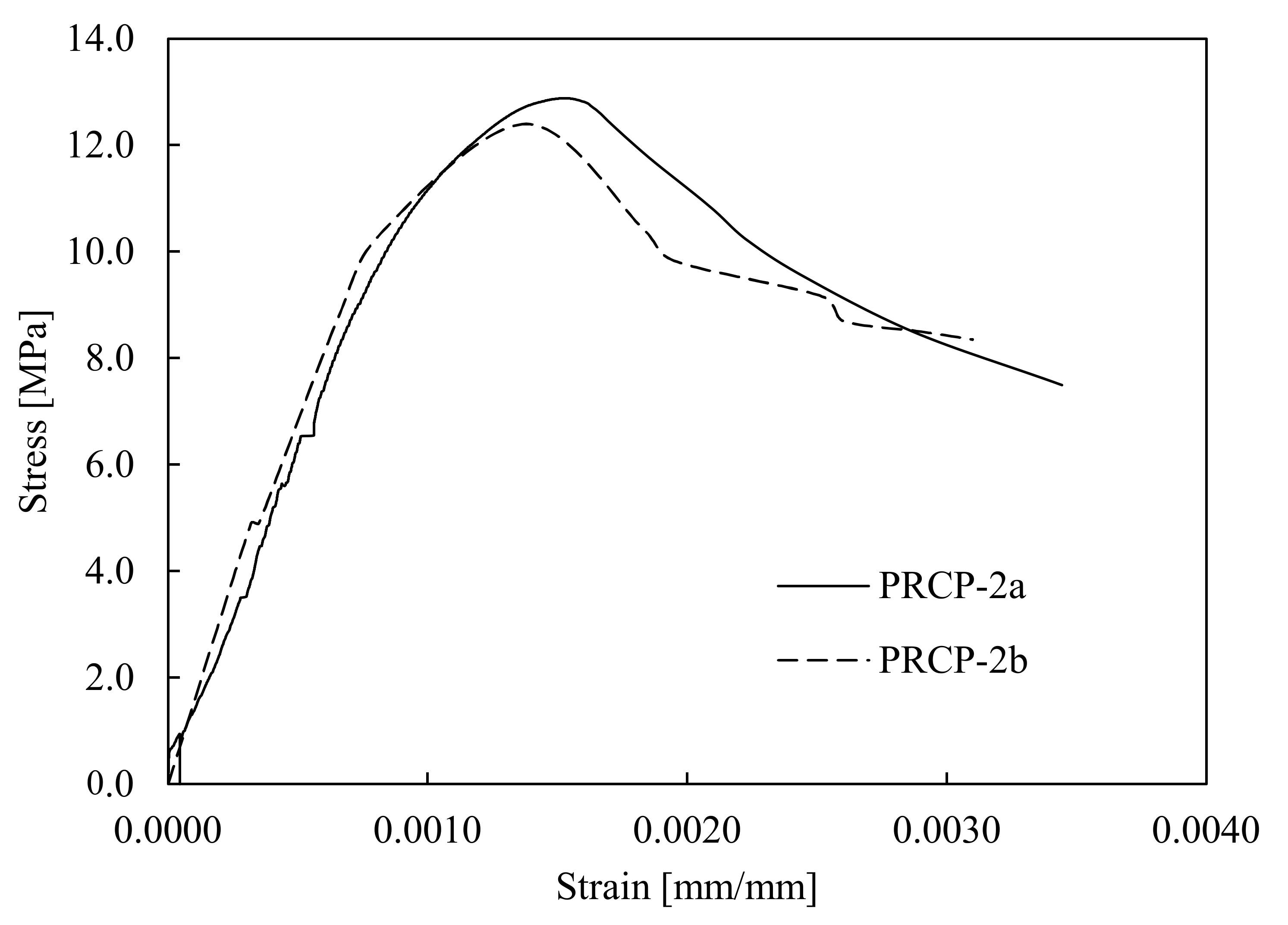
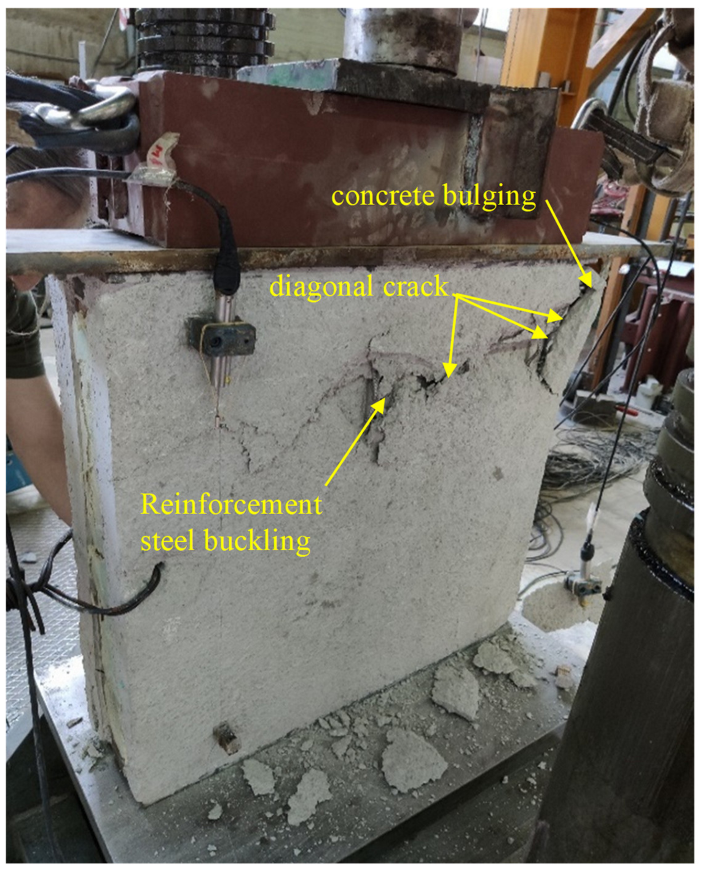
3.3.2. Stress–Strain Response and Failure Mechanism under Concentric Axial Compression of PCSP-2 Specimens

The obtained effective stress–strain curves for the investigated specimens are depicted in Figure 7. The effective strain was calculated using the average vertical displacement taken from the four LVDTs. Initially, the specimens exhibited elastic behaviour until the first micro-cracks appeared on the concrete panels. Afterwards, the behaviour became inelastic with small, almost horizontal cracks which began at the upper right corner and were expanded to the middle of the specimen. Cracks were observed at both of the concrete panels. Further loading increase caused outward concrete bulging. Beyond the maximum loading value, the existing cracks continued to widen, reaching 15 mm. This was also accompanied by the buckling of the reinforcement steel bars around the cracks, as shown in Figure 8. Both specimens failed in a ductile manner which can also be confirmed by the moderate slope of the descending part of the curves. The maximum load-bearing capacity was approximately 13 MPa, which is somewhat higher than the corresponding ones reported by [3]. In general, the failure was localized in a small area, indicating that the steel mesh worked effectively in preventing the expansion of the concrete crushing.

3.4. Diagonal Compression Tests on PCSP-3 Specimens

3.4.1. Experimental Setup and Instrumentation of PCSP-3 Specimens

Two 700 × 700 mm specimens, which were identical in component levels, were subjected to diagonal compression in order to determine their in-plane structural performance and resistance against shear loading. The test setup was composed of two steel loading shoes mounted on the two diagonally opposite corners of the specimen, as depicted in Figure 9. For this purpose, the investigated specimen was rotated at an angle of 45° to the horizontal direction. One loading shoe was placed on the top of the specimen to distribute the concentrated load directly from the hydraulic jack, and the other one was fixed to the floor in order to support the specimen. The aforementioned reaction frame was used in this test to apply the gradually increasing vertical monotonic displacement with a constant speed of 1.0 mm/min. The axial force was recorded using the load cell of the machine, whereas two LVDTs were attached to both sides to measure the vertical displacements. The measurements of the load cell and the LVDTs were recorded using a DAQ system at regular intervals with a frequency of 10 Hz.

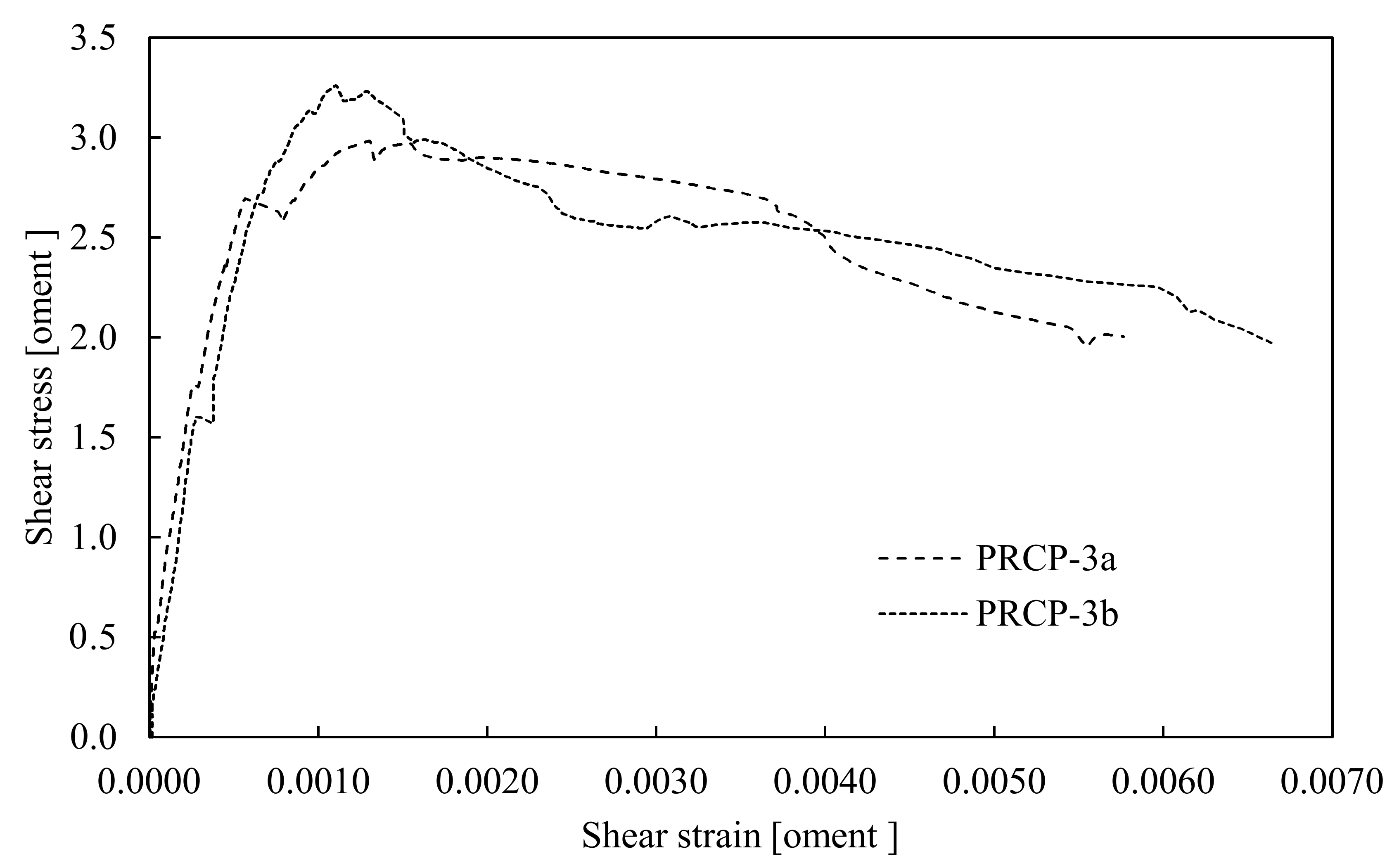
3.4.2. Stress-Strain Response and Failure Mechanism for the PCSP-3a,b Specimens

As has already been mentioned, both specimens were identical and thus their ultimate capacity was governed by the same failure pattern. The obtained effective shear stress–strain curves of both specimens, respectively, are depicted in Figure 10. For each specimen, the effective shear strain was calculated through the average vertical displacement obtained from both LVDTs mounted on the outward sides. At the early loading stages and upon the concrete’s tensile strength exceedance, small vertical cracks appeared and were marked as shown in Figure 11a. As the loading increased, a major crack developed in the right upper corner and was propagated in the bottom corner, as depicted in Figure 11b. In the post-peak region, the major crack continued becoming wider and was followed by partial concrete bulging. As was observed, the specimen failed in a ductile manner, and this was demonstrated through the moderate slope of the descending branch of the curve. This behaviour may be attributed to the steel reinforcement and the embedded shear connectors, which provided adequate confinement on the concrete and prevented a potential sudden failure. It should be noted that all the LVDTs were removed before the end of the test for safety reasons. The maximum shear resistance achieved in both cases was around 3.0 MPa, which is more than two times higher than the corresponding ones reported in relevant studies [23].

4. Experimental Investigation of Steel Bolted Joint Specimens

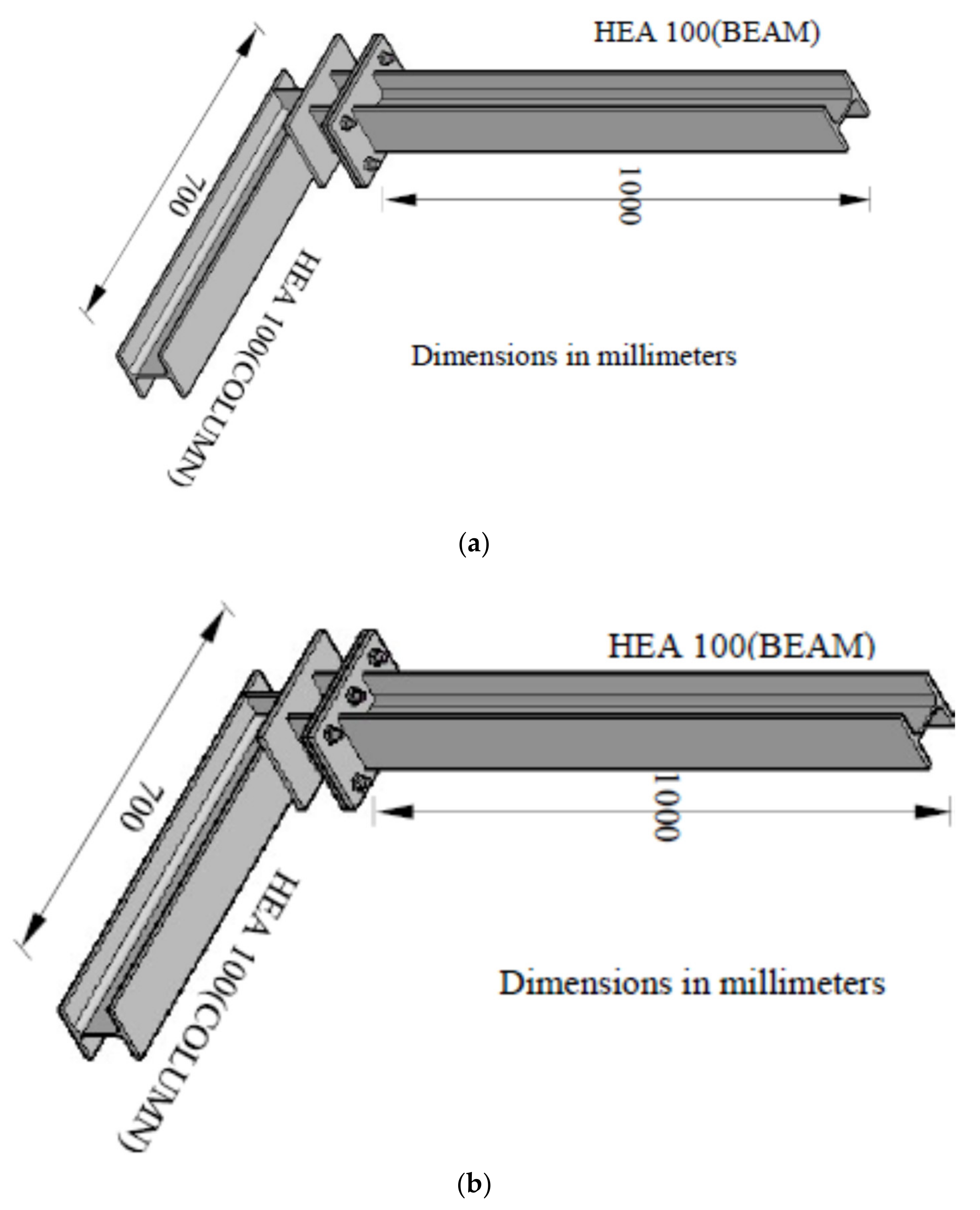
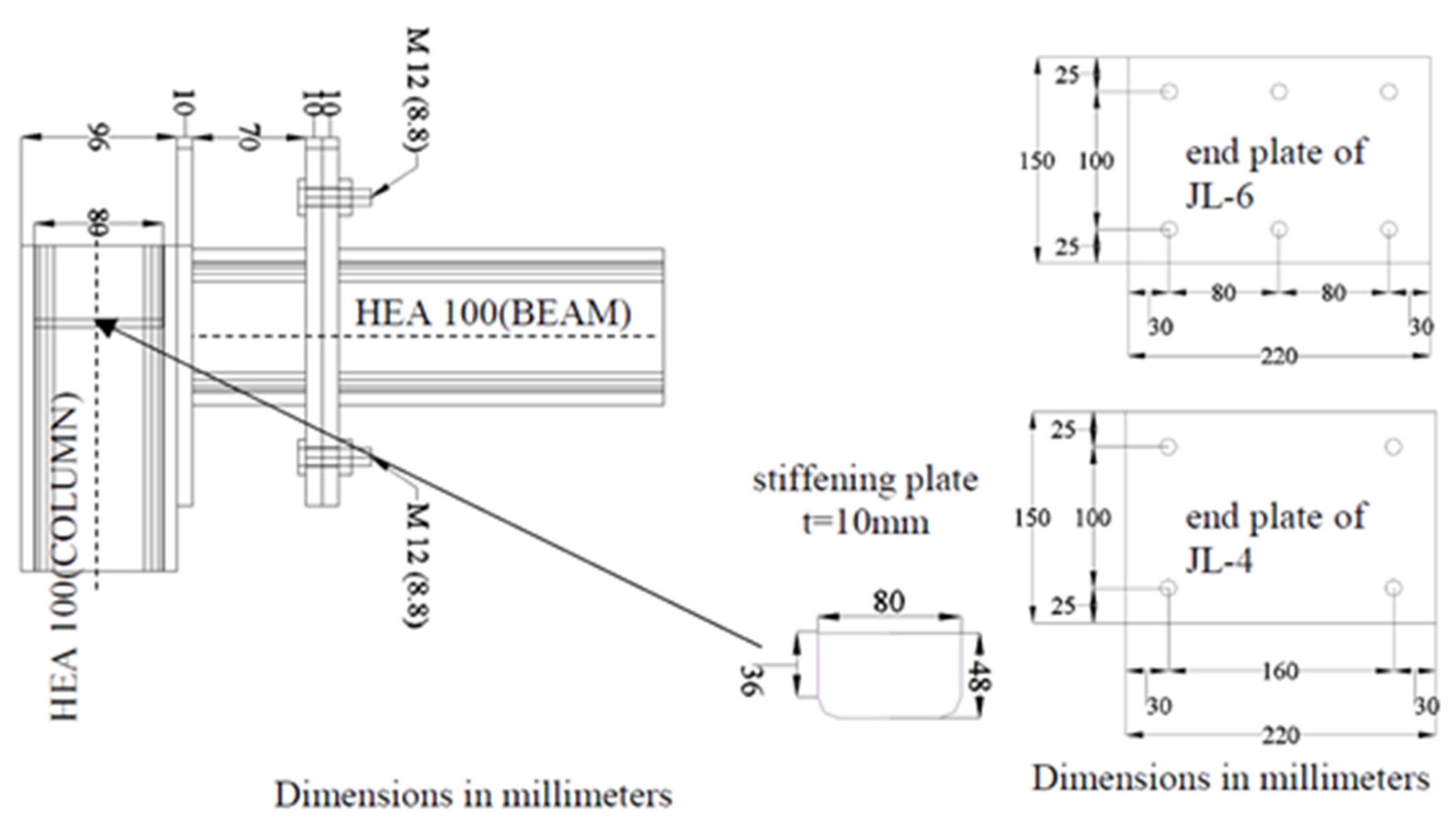
4.1. Geometrical Details of Steel Bolted Joint Specimens

Two steel bolted joint specimens that were identical in component levels were subjected to quasi-static cyclic loading in order to investigate their bearing capacity as well as their hysteretic behaviour. Three-dimensional schematic views of both specimens are displayed in Figure 12a,b. An additional 2-D schematic view of the bolted joint configuration, including geometrical details of the constituent steel connecting plates, i.e., end and stiffening plates, is shown in Figure 13. Both specimens were identical in terms of geometrical characteristics but had different bolt arrangements due to the different site of application along the vertical edge of the PCSP model.
More specifically, the configuration comprised four bolts in specimen JL-4 and six bolts in specimen JL-6 [24]. All the used bolts were M12 of grade 8.8, according to the EN 1993-1-8 classification. The connecting steel members, i.e., the beam and column, in a corner configuration representing the lower and the upper joint configuration of the system, were formed by HEA100(S235) cross-sections [25], and their lengths were 1000 mm for the beam and 700 mm for the column, respectively. They were connected using two end plates, one of which was welded to the beam and the other was welded onto a supplementary member (for serviceability reasons) of an HEA100(S235) section and a small length of 70 mm, which was equal to the designed gap. This member was welded onto a third end plate, which was also welded onto the column steel member. These three used end plates had the same dimensions of 150 × 220 × 10 mm. In addition, two stiffening plates were welded onto the column web and flanges underneath the end plate so that any local failure due to concentrated loading could be prevented.
The welding configuration was composed of fillet welds with a 235 MPa nominal yield strength and a 5.0 mm throat thickness in line with the EN 1993-1-8 [26] requirements. It is noteworthy that after welding an ultrasonic technique was used to ensure that the quality requirements of welding were fulfilled.

4.2. Tensile Coupon Tests

All joint components were made of the same steel quality, and the material properties were determined by conducting tensile coupon tests in line with [27]. Two flat coupons of the representative material of the sections and the plates of the specimens were tested with a nominal width and gauge length of 10 mm and 100 mm, respectively. An INSTRON machine with a 250 kN maximum capacity was used to perform the tests with a strain rate of 0.2 mm/min.

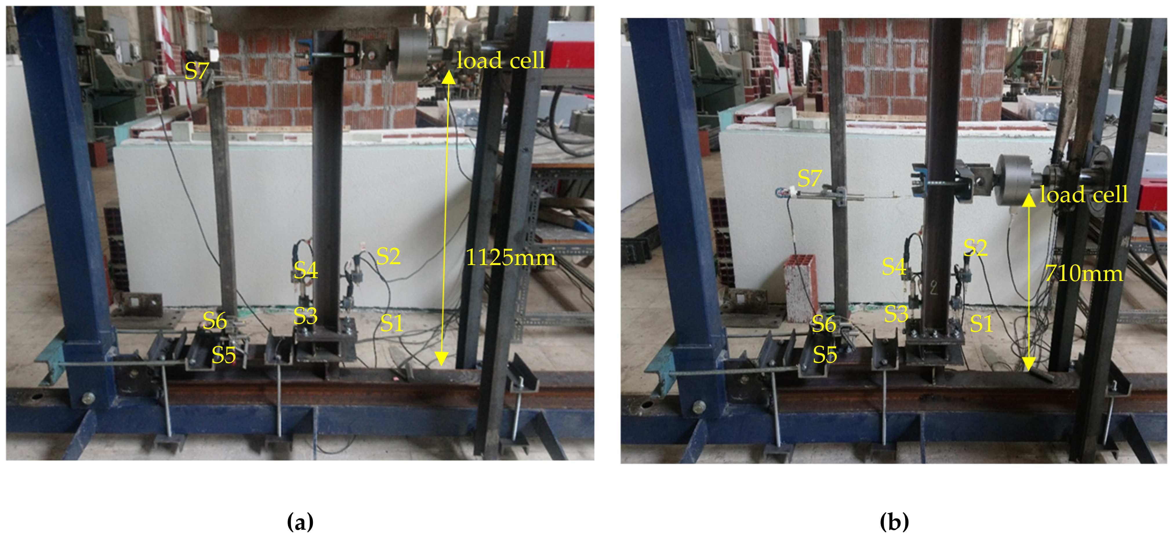
4.3. Experimental Setup and Instrumentation of the Steel Bolted Joint Specimens

A reaction frame anchored on the laboratory strong floor and a hydraulic MTS actuator with a 2500 kN maximum capacity were used for the execution of the cyclic tests on the JL-4 (Figure 14a) and JL-6 (Figure 14b) specimens, respectively. It is noteworthy that the testing procedure, which was followed in the respective cases of the specimens, was identical. The column of the specimens was laid over a horizontal steel frame element of the laboratory so that the beam could be perpendicular to the floor. The column edge was fixed to the reaction frame using two horizontal and two vertical anchors, whereas the beam edge was free. Two additional vertical anchors were placed at a 400 mm distance from the column edge to prevent the uplifting of the specimen during the test.
The hydraulic actuator was horizontally positioned at a 1125 mm distance from the column in specimen JL-4 and 710 mm from the column in JL-6, respectively. The employed instrumentation comprised seven LVDTs in total to measure the various displacements of the joint components: S1 and S3 for the vertical displacement of the lower bolted end plate, S2 and S4 for the vertical displacement of the upper bolted end plate, S5 for the horizontal displacement of the lower bolted end plate, S6 for the horizontal displacement of the upper bolted end plate, and S7 for the horizontal displacement of the beam’s edge.

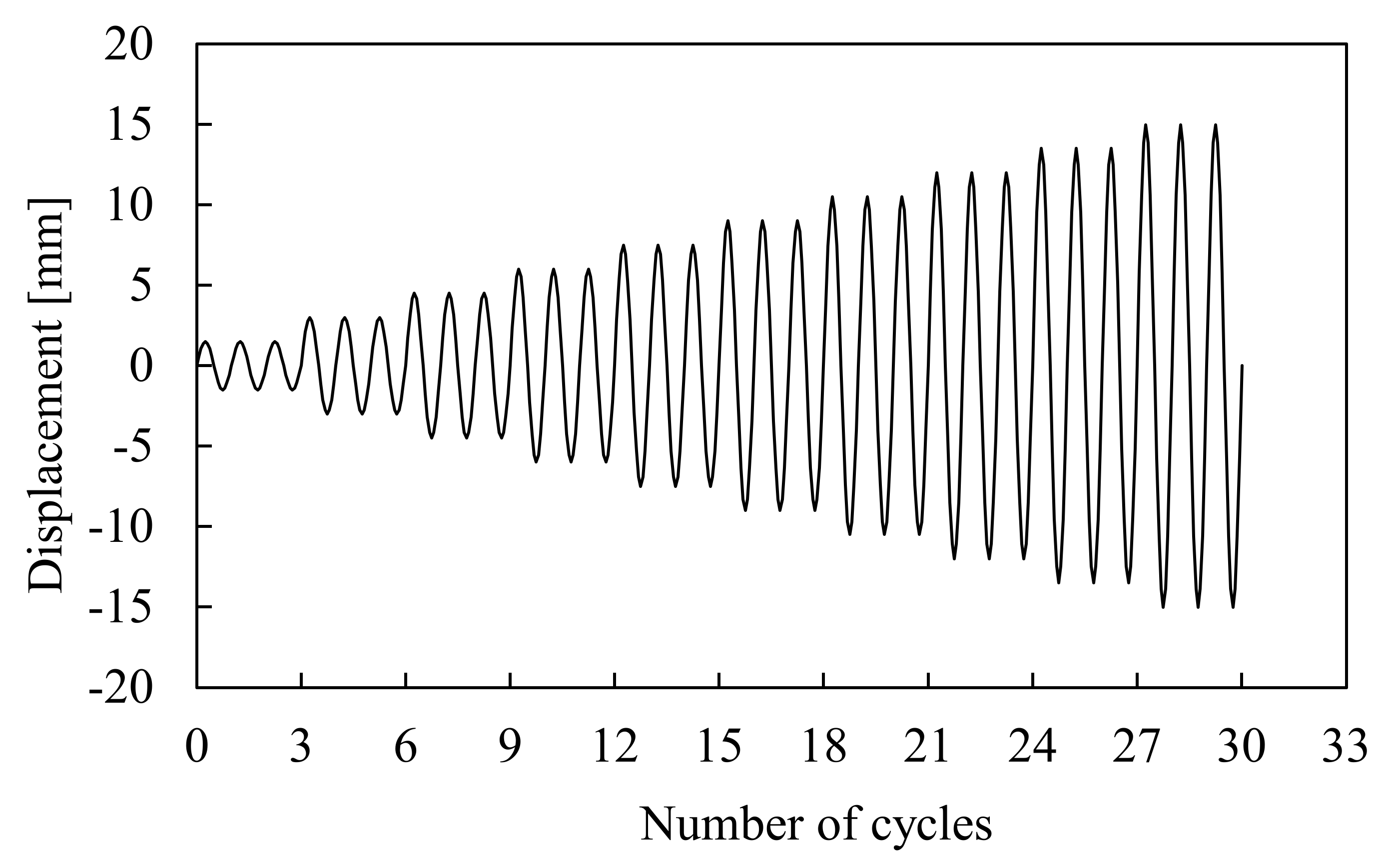
4.4. Applied Loading Scheme on the Steel Bolted Joint Specimens

Prior to testing, load deformation cycles of ±2 mm were implemented to ensure that the overall instrumentation was working properly and all the gaps were closed. In order to utilise the obtained results of the quasi-static cyclic tests, there was a need to define a loading history scheme capable of capturing the critical issues of the structural performance [28]. A particular emphasis was given to the excursions in the inelastic range as they cause cumulative damage leading to an ultimate limit state. The applied loading scheme included a load deformation history with three cycles at each displacement amplitude (Figure 15), where the yield displacement was used as reference for increasing the amplitude of the loading cycles.
The hydraulic actuator was driven by a displacement control method and applied to a quasi-static cyclic loading with a rate of 0.02 mm/s. The test was terminated upon the bolted joint’s failure occurrence. All measurements were recorded using a DAQ system at regular intervals with a frequency of 10 Hz.

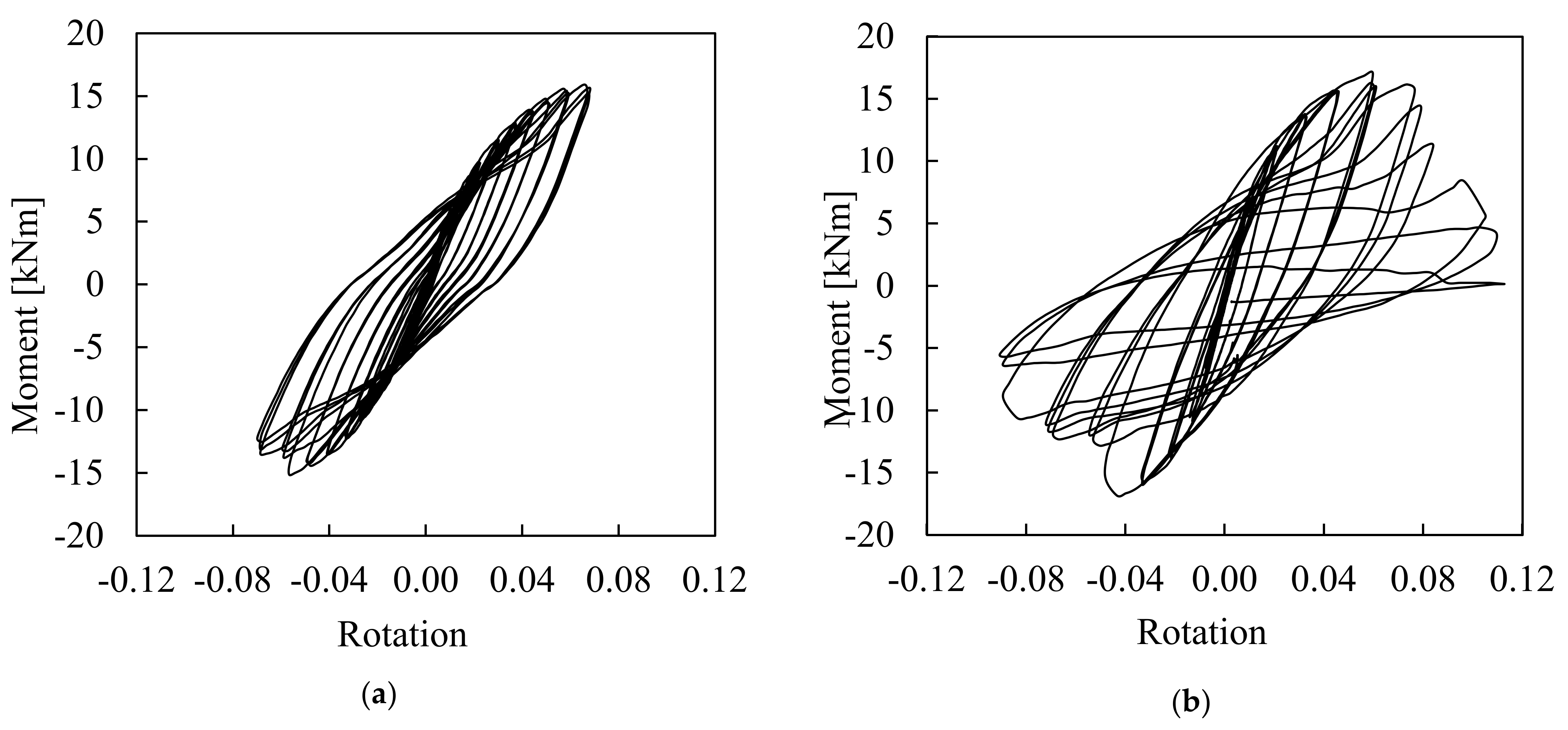
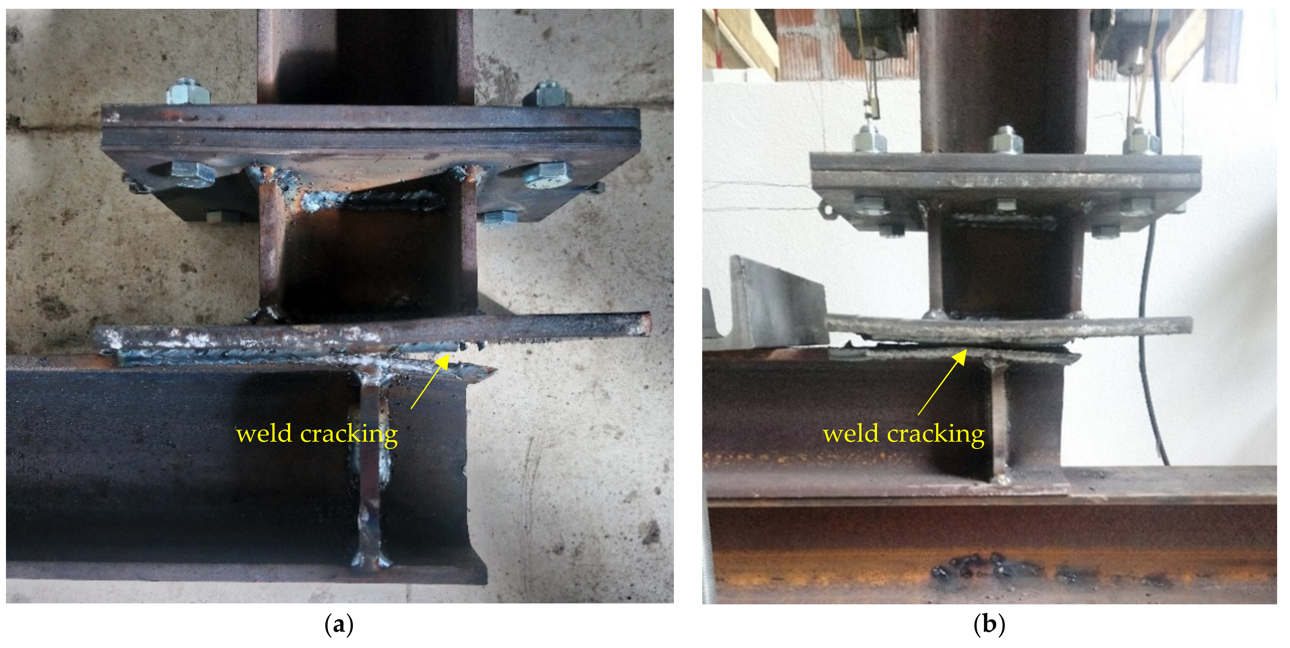
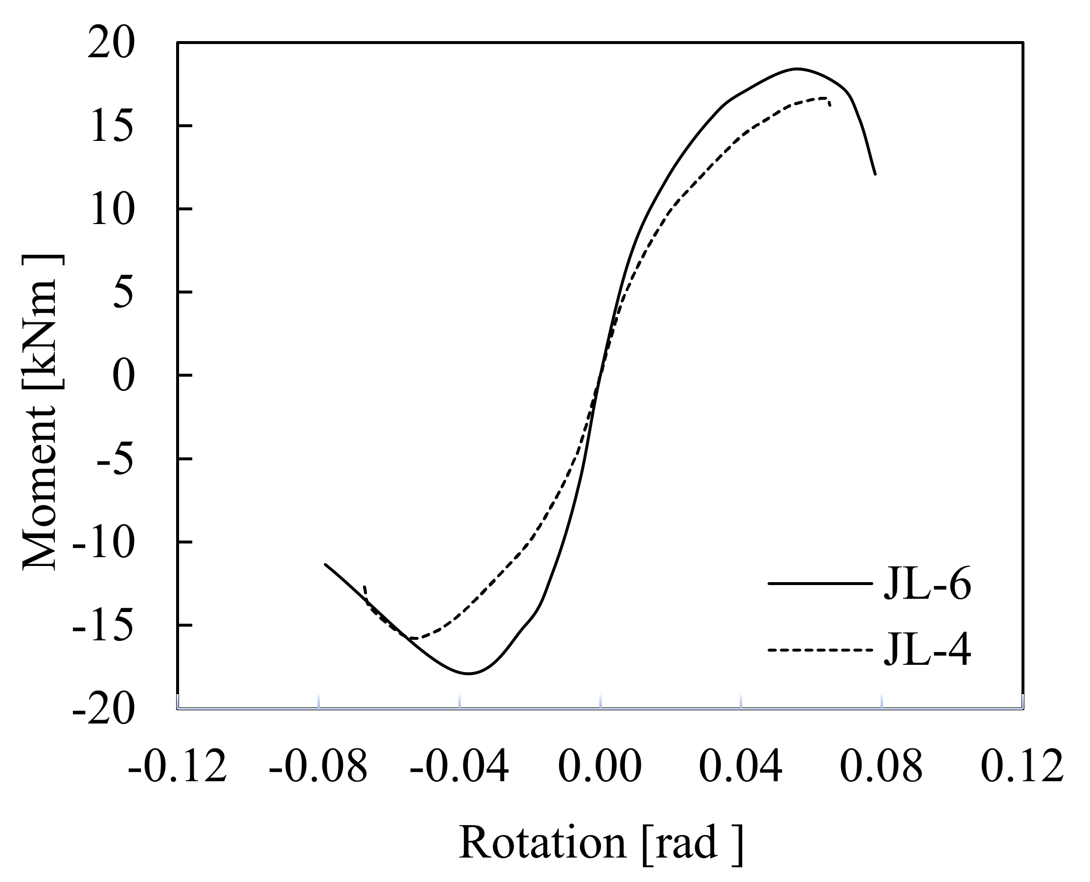
4.5. Moment–Rotation Response and Failure Mechanism of the Steel Bolted Joint Specimens

Upon testing, the obtained results are presented and discussed in terms of moment–rotation response, failure mode, load-bearing capacity, ductility, and energy dissipation capacity [29]. Comparisons between the examined steel bolted joints are also made. In the first two loading cycles, both the JL-4 and the JL-6 specimens, respectively, exhibited a linear response. Following that, plastic deformations arose in the vicinity of the corner and their magnitude increased rapidly with the increase in the imposed displacement. Upon the attainment of the ultimate load, a sudden major crack occurred in the weld between the end plate and the column. The crack began underneath the right side of the end plate where the concentration of the tensile stresses was higher and propagated along the welding line. When a reverse load was imposed, the crack closed up and the specimen continued to endure loading throughout large inelastic deformations. As the crack was expanding, the joint stiffness and capacity were severely degraded. Although both joint specimens, they enabled a ductile failure mechanism. No obvious plastic deformations were observed in the rest of the components of the specimens during testing. The failure mechanisms were identical in both specimens, as shown in Figure 16a,b.
The obtained moment–rotation curves for both specimens are illustrated in Figure 17a,b. The applied moment (M) is calculated by multiplying the force imposed from the hydraulic actuator and the lever arm measured by the upper flange of the column. The rotation (θ) is taken by dividing the displacement of the beam’s edge, where the force was imposed, by the corresponding lever arm.
It should be remarked that the response in the post-ultimate range for the JL-4 specimen was not recorded for safety reasons as it was tested first. For both specimens, the corresponding hysteresis loops show a stable response against in-plane bending. Moreover, the Bauschinger effect is apparent but not so pronounced. A slight increase in the ultimate capacity can also be observed with the increase in the applied loading. Moreover, the hysteresis loops of both specimens seem to be plump, denoting satisfactory energy dissipation capacity.
For comparison purposes, both skeleton curves are plotted in the same graph, as displayed in Figure 18, and each skeleton curve in the graph is obtained by connecting each point corresponding to the maximum load of each hysteresis loop. Again, it can be seen that the overall structural response of each specimen, respectively, is similar. Even though JL-6 is stiffer, having two additional bolts, there is no significant difference at the ultimate load-bearing capacity, which is around 16 kNm in both cases. This is attributed to the fact that the failure was independent of the bolted joint’s stiffness as this occurred due to welding failure. The tested specimens may sustain more loading if the welding configuration was sufficiently designed using fillet welds with larger welding thickness and a higher end length of the respective supported column. With regard to the energy dissipation capacity, both specimens seem to be able to absorb an equal amount of energy as the area enclosed by the hysteresis loops is roughly the same.

5. Experimental Investigation of a Novel Precast Reinforced Concrete Panel-Infilled Steel Frame (PCSP-ISF) Model under In-Plane Cyclic Loading

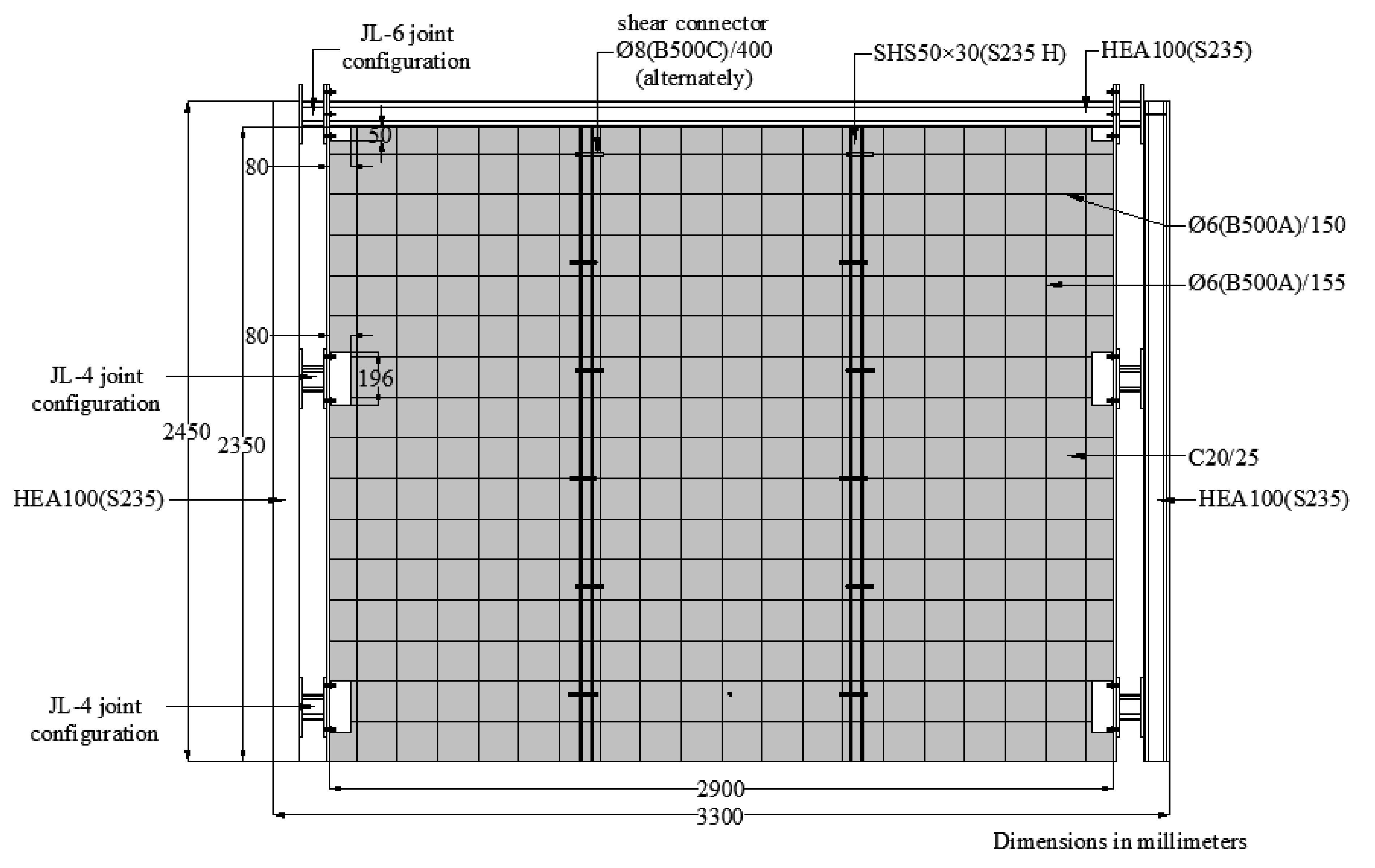
5.1. Geometrical Details of Test PCSP-ISF Model

Upon completion of the tests of the conceptual specimens of the components and after a detailed quantification procedure of their structural performance, an experimental investigation of a model at a system level was performed. Based on observations and considering the obtained capacities, a PCSP-ISF model was designed in full-scale and subjected to in-plane cyclic loading.
The PCSP-ISF model was designed with 3300 × 2450 mm dimensions in the front view, corresponding to a typical residential building (see Figure 19). The steel frame consisted of a steel beam of an HEA100 (S235) section on the top, supported by two respective columns of an HEA100 (S235) section [25] and was filled inside with a PCSP wall system, using the previously examined JL-4 and JL-6 bolted joint configurations.
The JL-4 configuration was applied at the middle and at the lower joint of the PCSP-ISF model. It was mentioned that the bolted joint at the corner top connected both the steel beam and the wall with the steel column due to the preconstruction procedure explained before. The layout of the PCSP-ISF configuration (see Figure 20), with one column placed with its local major axis longitudinally to the wall and the respective one on the other end transversally, was taken because it is the most typical arrangement for steel building frames. Between the PCSP wall and the steel frame were free gaps for operational and serviceability reasons. It should be mentioned that the bolted joint connections were accomplished with particular attention, assuring that all the components worked together, and the applied loading action could be successfully transferred to the supports. According to the detailed tests on the conceptual specimens of the components and many other theoretical and numerical research analysis concepts of the structural model, the PCSP wall was modelled so as to be more stable and less susceptible to out-of-plane bending. More specifically, two 50 × 30 mm vertical SHSs (S235 H) sections with 235 MPa nominal yield strength were placed in the core at equal distances in its width. The two respective concrete panels were reinforced in the middle with Ø6/(150 × 155) mm of quality B500A reinforcement steel net, attached with full contact to the inside sited vertical SHSs or to the insulating material. Moreover, the inside sited vertical SHSs members were connected to either of the respective concrete panels with shear steel bars welded onto the SHSs’ free edges at vertically distributed distances of 400 mm, alternately. The foregoing connecting reinforcement consists of 8 mm in diameter quality B500C steel bars in accordance with the requirements specified by [18]. The aforementioned connecting reinforcement consists of 8 mm in diameter quality B500C steel bars.

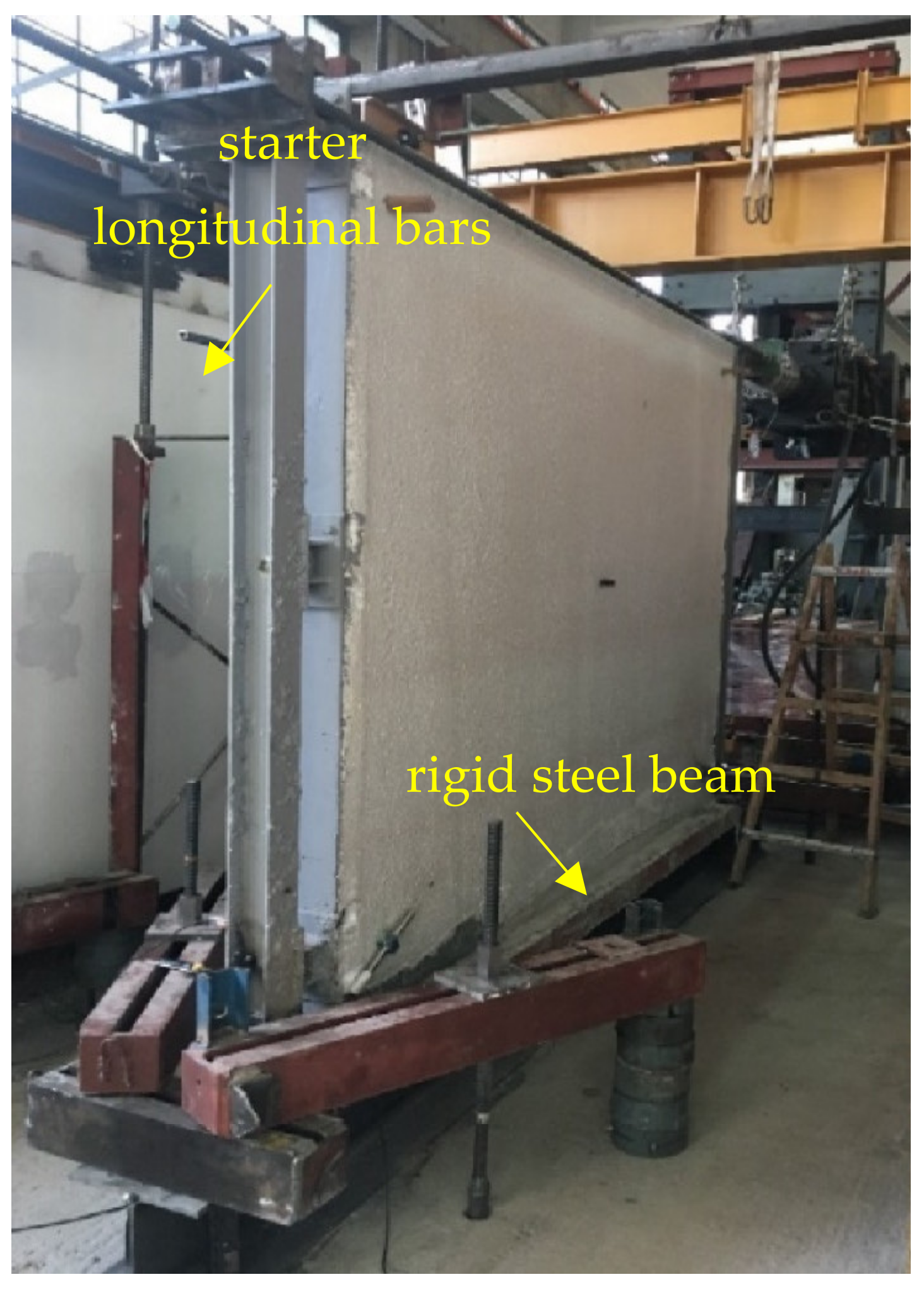
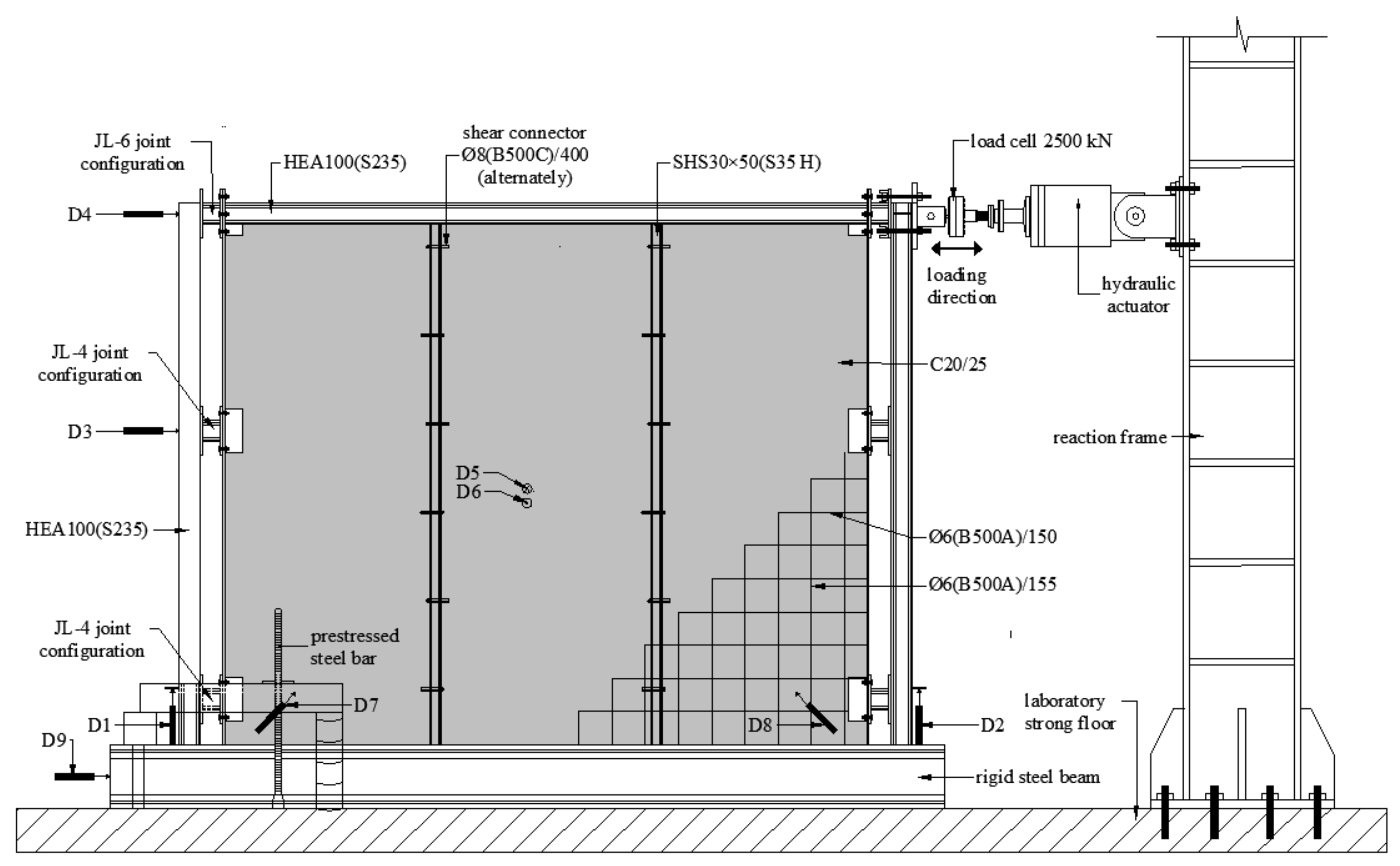
5.2. Experimental Setup and Instrumentation of the PCSP-ISF Model

The PCSP-ISF model was placed carefully and its free displacements at the bottom ends were fixed using a rigid steel beam which was clamped on the laboratory strong floor using projected prestressed steel bars, as shown in Figure 21. A hydraulic MTS actuator with a 2500 kN maximum capacity was used to apply quasi-static in-plane cyclic loading.
On one side, it was positioned horizontally at the top edge of the steel frame, and on the other side, it was connected to the reaction frame. In total, nine LVDTs were attached to monitor the various displacements of the PCSP-ISF model: D1 and D2 were attached to measure the uplifting of the rigid steel beam, D3 and D4 were attached to the connection points of the respective joints bolted to the left steel column to record the horizontal displacements, D5 and D6 were attached to the external surface of the PCSP wall to measure the out-of-plane displacement, D7 and D8 were attached at the two lower corners to record the diagonal displacements, and finally, D9 was attached to measure any slippage of the laboratory supporting steel beam. The employed set up and instrumentation of the PCSP-ISF model are displayed in Figure 22.

5.3. Applied Loading Scheme on the PCSP-ISF Test Model

Prior to testing, load deformation cycles of ±1 mm were implemented to ensure that the overall instrumentation was working properly, and all the gaps were closed. The load deformation history scheme was partially based on the ATC-24 [30] loading protocol, giving particular emphasis to the excursions in the inelastic range as they cause cumulative damage leading to an ultimate limit state [28,31]. The hydraulic actuator was driven by a displacement control method and applied the quasi-static cyclic loading with rate of 0.10 mm/s. Increasing displacement amplitude multiples of the yield displacement were imposed in each direction up to failure. The applied loading scheme is shown in Figure 23. All measurements were recorded using a DAQ system at regular intervals with a frequency of 10 Hz.
No axial load was added at the upper side of the specimen. The basic idea of the research project was that the same destructive critical size of the PCSP identical test specimen was used to investigate and calibrate the critical buckling behavior of the cross-section of the specimen [15] in the longitudinal direction (vertical direction of the wall) with respect to several numerical tests. This was made by converting the ultimate transverse load received by the test to an equivalent critical buckling load of the critical simple supported model and thus obtaining the pre-buckling and post-buckling behavior and their respective displacements. So, in order to avoid an overestimation of the contribution of the compressive vertical load acting on the wall through the beam on the upper part of the specimen in the dynamic load states, as this acts mainly to reduce the tensile and shear forces caused on the wall panels, this was not set simultaneously during the experiment.

5.4. Experimental Results and Discussion on the PCSP-ISF Test Model

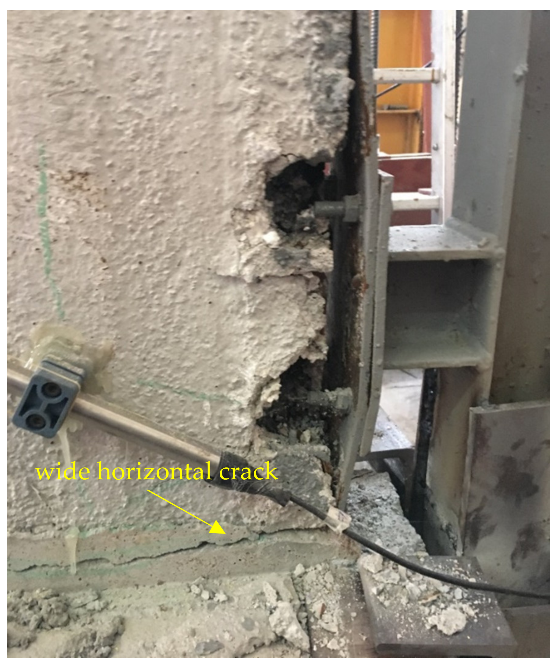
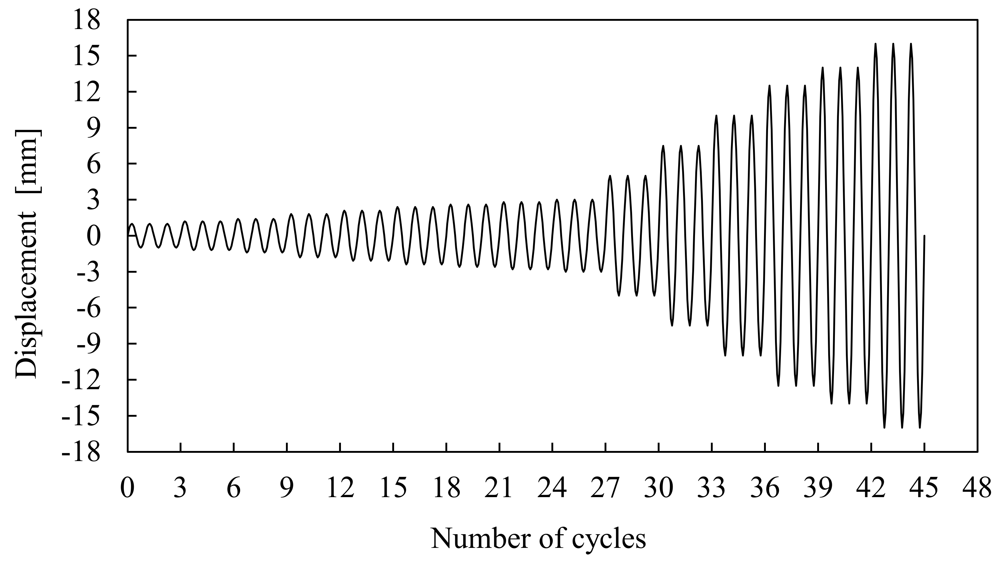
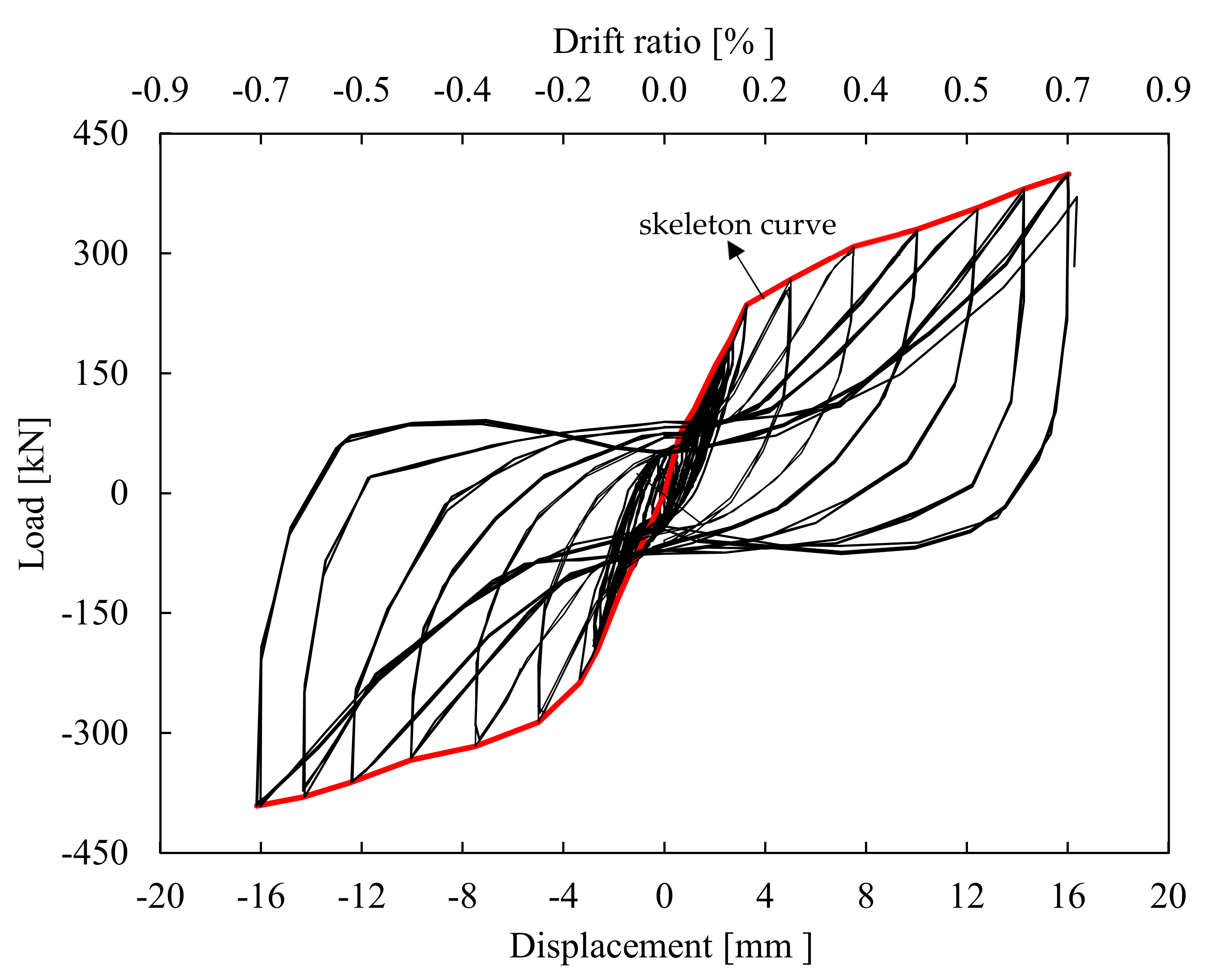
5.4.1. Load-Displacement Response and Failure Mechanism of the PCSP-ISF Test Model

The hysteretic response of the investigated PCSP-ISF test model is presented in Figure 24 in the form of load versus displacement loops. Based on past studies [32,33,34,35], the structural deformation of a well-designed frame structure can be used to estimate expected damage. The ratio of the interstorey drift or simply the drift ratio, which is equal to the maximum relative displacement between two consecutive stories divided by the storey height, is considered as a quite important damage estimator. Thereby, the imposed drift ratio during testing is also included in the plotting results.
Based on the resulting test data, during the first four loading cycles the specimen exhibited a linear behaviour without residual deformations. Following that, in the 5th cycle, micro-cracks began at the joint regions where the normal stresses derived from the bending moments exceeded the concrete’s tensile strength. In the subsequent loading cycles, and up to 3 mm, the cracks became wider and longer, and new ones began at the top and bottom of the PCSP along the horizontal and vertical direction. Moreover, the two lower steel joints were plasticised and experiencing plastic deformations. This can also be confirmed by an obvious turning point in the skeleton curve included in Figure 24. In the following loading cycles, and up to 14 mm, imposed displacement diagonal hairline cracks shorter than 150 mm developed in the top of the PCSP wall in the regions between the steel columns and the respective SHS members. These cracks formed at a 45° angle and extended towards the center of the PCSP but without becoming considerably wider. Meanwhile, the intermediate and top steel bolted joints reached their plastic resistance, whereas concrete spalling was observed around the region of the corresponding ones in the bottom. Generally speaking, up to this point no significant damages or cracks were observed in the concrete of the PCSP panels and the bolted joints with the steel frame. The beneficial role of the well-detailed horizontal and vertical reinforcement and the elastic contact with the SHS members, along with the embedded shear bar connectors, provided adequate restraint against diagonal compression.
The nonlinear behavior of these shear bars allowed for better redistribution of the shear stresses and prevented the widening of the shear cracks. At the last loading cycle of 16 mm imposed displacement, new diagonal cracks developed at the upper and middle part of the PCSP concrete panels, and the existing one increased rapidly, reaching a 15 mm width. A wide horizontal fracture also appeared in the lower right corner of the PCSP concrete panels. The significant concrete cracks resulted in a considerable pinching phenomenon of the relative hysteresis loop as it appeared to be narrower around the origin. Furthermore, the two lower bolted joints experienced severe plastic deformations, as shown in Figure 25. Despite the fact that the PCSP-ISF test model continued to sustain loading beyond the maximum load-bearing capacity, the LVDTs were removed, and the experiment was terminated for safety reasons. It is noteworthy that the measured vertical displacement of the rigid beam was negligible throughout the testing, indicating that its anchorage on the strong floor prevented the PCSP-ISF from rocking.
The corresponding out-of-plane displacement measurements also confirmed the absence of instability phenomena due to the PCSP-ISF’s small thickness-to-width ratio. The obtained hysteresis characteristics, including yield strength (Fy), yield displacement (δy), maximum strength (Fmax), maximum displacement (δmax), ultimate strength (Fu), ultimate displacement (δu), maximum drift ratio (θ), initial stiffness (Kinit), and ductility factor (μδ), are summarised in Table 2. The initial stiffness was defined as the slope of the skeleton curve at the first loading cycle. The yield displacement was obtained through the bilinearisation of the experimental load displacement curve, as described in Annex B of EN 1998-1 [36]. The ultimate state is defined as the point of the skeleton curve corresponding to a 20% decrease in the maximum strength when considering the existence of a considerable deformation capacity beyond the maximum strength [37,38]. Herein, the experiment was terminated without capturing the response at the post-peak range, and thus, the ultimate state was considered the point corresponding to maximum strength and displacement.
As can be seen, the drift ratio obtained in the current investigation is 0.7% and thereby below the 2.5% maximum value specified in [38] as a life-safety performance level for an earthquake with a 10% probability of being exceeded in 50 years. The investigated structural system could attain a higher maximum drift ratio as the premature termination of the experiment did not enable it to reach failure.
The buckling behavior and the respective out-of-plane displacements of the cross-section of the wall in the longitudinal direction (vertical direction of the wall), through a PCSP identical test specimen, were investigated with respect to several numerical tests, as well as the same buckling behavior during the PSPF-ISF in both directions. From the total program of experimental and numerical tests was defined a successful shear connection between the wall panel and the surrounding steel frame. So, the out-of-plane behavior and capacity of the PCSP-ISF depends on the respective out-of-plane capacity of the surrounding steel frame. Thus, by designing an optimal form of the load-bearing system of the 3-D building with equally distributed PSPF-ISF panels in both main directions of the system, the capacity of the steel frame members decreases significantly, and there is no reason to overestimate the out-of-plane capacity of the wall.

5.4.2. Ductility Factor of the Tested PCSP-ISF Model

The ductility factor is considered as an important parameter of the seismic performance of a structure. It shows the capability of a structure to sustain large deformations under cyclic loading without significant loss of strength and can be expressed in terms of various deformations, such as displacements, rotations, and curvatures. In the present study, the ductility factor (μδ) is calculated in terms of displacement using the following Equation (1) [39]:
μ δ = δ u δ y
where δu is the displacement at the ultimate state, and δy is the displacement at the yielding state, as described in Section 5.4.1. Therefore, the displacement ductility factor for the investigated structural model was equal to μδ =3.9. This value underestimates the real deformation capacity as the test was terminated before the PCSP-ISF reached failure. However, the calculated displacement ductility factor denotes a satisfactory ductile performance.

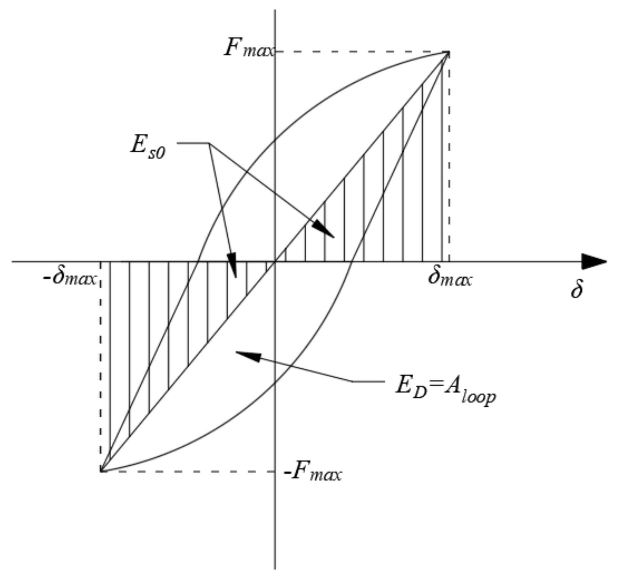
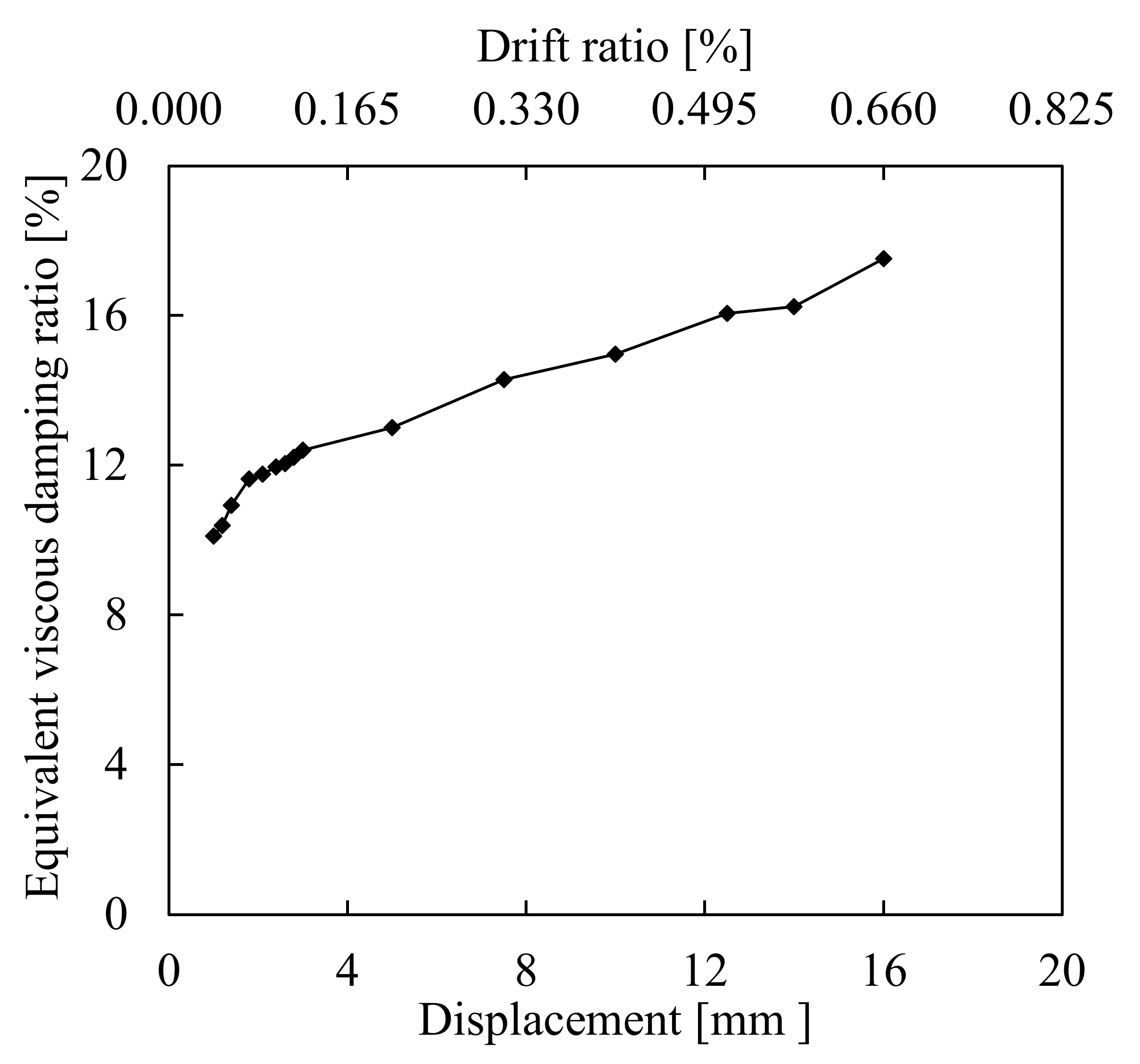
5.4.3. Equivalent Viscous Damping Ratio of the Tested PCSP-ISF Model

A structural system dissipates energy while exhibiting an inelastic response under cycling loading. The energy dissipation capacity is of great significance while evaluating the effectiveness and the seismic resistance of a structural system. The hysteretic damping which corresponds to the energy absorbed per loading cycle is a common indicator of the energy dissipation capacity and can be translated to an equivalent viscous damping ratio (ξeq) according to Equation (2) [38,39,40]:
ξ e q = E D 4 π E s 0 = A l o o p 2 π F m a x δ m a x
where ED is the energy dissipated at a single loading cycle and is equal to the area, Aloop, enclosed by the corresponding hysteresis loop, Es0 is the elastic energy stored in an equivalent linear elastic system which equals the total area of the shaded triangles (Figure 26), Fmax is the maximum load, and δmax is the maximum displacement. Moreover, the hysteretic equivalent damping ratio values were calculated as average values among three loading cycles for each displacement amplitude and were plotted versus the respective displacements (Figure 27).
It could be seen that in the initial loading cycles the hysteretic damping ratio gradually increases while the response of the PCSP-ISF is within the elastic range. Beyond the 3 mm displacement, and as the imposed displacement increases, the constituent elements step into the plastic range. The large amount of energy dissipated through the concrete cracks and the plastic hinges caused in the steel joints resulted in a higher energy dissipation capacity. The same conclusion can be drawn from the hysteresis loops which enclose a larger area while the imposed displacement progressively increases. The average equivalent viscous damping ratio achieved during testing (see Figure 27) was 13%, which is somewhat larger than the reported ones in the relevant studies [2].

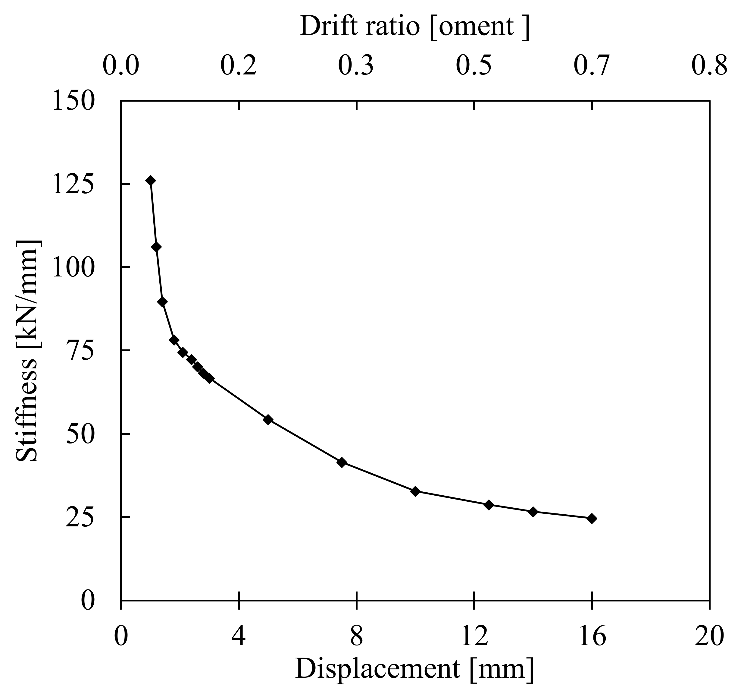
5.4.4. Stiffness Degradation during Testing of the PCSP-ISF Model

Figure 28 presents the stiffness degradation during testing in the form of a secant stiffness corresponding to each loading cycle versus displacement. The secant stiffness is evaluated using the following Equation (3):
K i = + P i + P i + δ i + δ i
where Ki is the secant stiffness at the ith loading cycle, +Pi and −Pi are the maximum strength at the ith positive and negative cycle, respectively, and +δi and −δi are the corresponding displacements at the ith positive and negative cycle, respectively. It is noteworthy that the stiffness of the system was calculated as the average value among the three loading cycles per displacement amplitude.
According to the graph of Figure 28, the initial stiffness of the PCSP-ISF model degrades by almost 80%, following a power law throughout testing. It can also be observed that the stiffness exhibits the highest loss at low levels of displacement amplitudes, and thereafter, it continues to decline with a smoother branch by the end of the testing. Conversely, the reported results [34,41,42] for masonry-infilled steel frames denoted that the stiffness degrades at a rather slower rate at low displacement amplitudes. This may be attributed to the relatively homogeneous behaviour of the PCSP compared to the masonry infill.

6. Theoretical Shear Capacity of the PCSP-ISF Model

In the absence of codified rules for the prediction of the shear capacity of PCSP-ISFs, the current study utilizes the existing design criteria for masonry-infilled frames derived from FEMA 306 [43], substituting the corresponding material properties. According to this methodology, the PCSP could be replaced by an “equivalent diagonal strut” with the material properties and thickness of the actual infill. In order to analyse more accurately the in-plane behaviour of the infill, ASCE/SEI 41-13 [44] suggests adopting one or two diagonal struts for aspect ratios smaller or larger than 1.5, respectively. Hence, for this study, a single equivalent strut was adopted for the theoretical analysis. Taking into account the experimental results, the dominant failure mode of the PCSP-ISF was the corner crushing of the PCSP, and thereby, the shear capacity (VPCSP) can be determined using the following Equation (4) for the compression failure of the “equivalent diagonal strut” [43]:
V P R C P - I S F = a t P R C P f c k c o s θ
where α is the width of the equivalent diagonal strut, which can be defined using Equation (5), tPCSP is the thickness of the PCSP, fck is the cylinder compressive strength of the concrete, and θ is the slope angle of the PCSP’s diagonal, equal to tan−1 = (hPCSP/lPCSP), where hPCSP and lPCSP are the height and length of the PCSP, respectively.
a = 0.175 λ 1 h c o l 0.4 r i n f
where λ1 is a factor which can be estimated using Equation (6), hcol is the column height, and rinf is the diagonal length of the PCSP.
λ 1 = Ε P R C P t P R C P s i n 2 θ 4 Ε f r I c o l h P R C P 1 4
where EPCSP and Efr are the Young’s modulus of the PCSP and steel frame, respectively, and Icol is the moment of inertia of the column.
The theoretical calculation approach for the shear capacity of the investigated PCSP-ISF is 446 kN, which is 12% higher than the corresponding result from the test (Table 2). This difference seems to be reasonable considering the complex developed mechanisms of a PCSP-ISF under an in-plane lateral loading. It can be concluded that this theoretically applied method, which was originally developed for masonry-infilled frames, can be utilized for the estimation of the shear capacity of PCSP-ISFs with satisfactory accuracy. However, further validation based on experimental data is needed in order to identify the potential limitations and demonstrate further the applicability of this method for PCSP-ISFs.

7. Conclusions

This paper presents an experimental research study on the seismic performance of a novel Precast Reinforced Concrete Panel-Infilled Steel Frame (PCSP-ISF) in full scale. Prior to testing, experimental investigation of its constituent elements, which are several PCSP specimens and representative specimens of steel bolted joints, was conducted in order to obtain a better understanding of this complex structural system. The major observations and conclusions from the overall study are summarised below:
  • The PCSP-1 specimen under three-point bending failed due to a wide flexural crack in the mid-span of the tensile concrete panel. It was observed that the presence of the steel mesh reinforcement and the embedded shear connectors significantly enhanced the load-bearing capacity, preventing a potential brittle failure. The obtained maximum capacity of the out-of-plane bending was 16.5 kNm.
  • The PCSP-2 specimens under concentric axial compression attained a maximum capacity of 13.0 MPa. The failure mechanism included cracks in the mid-height of the concrete panel, buckling of the reinforcement steel mesh, and concrete bulging.
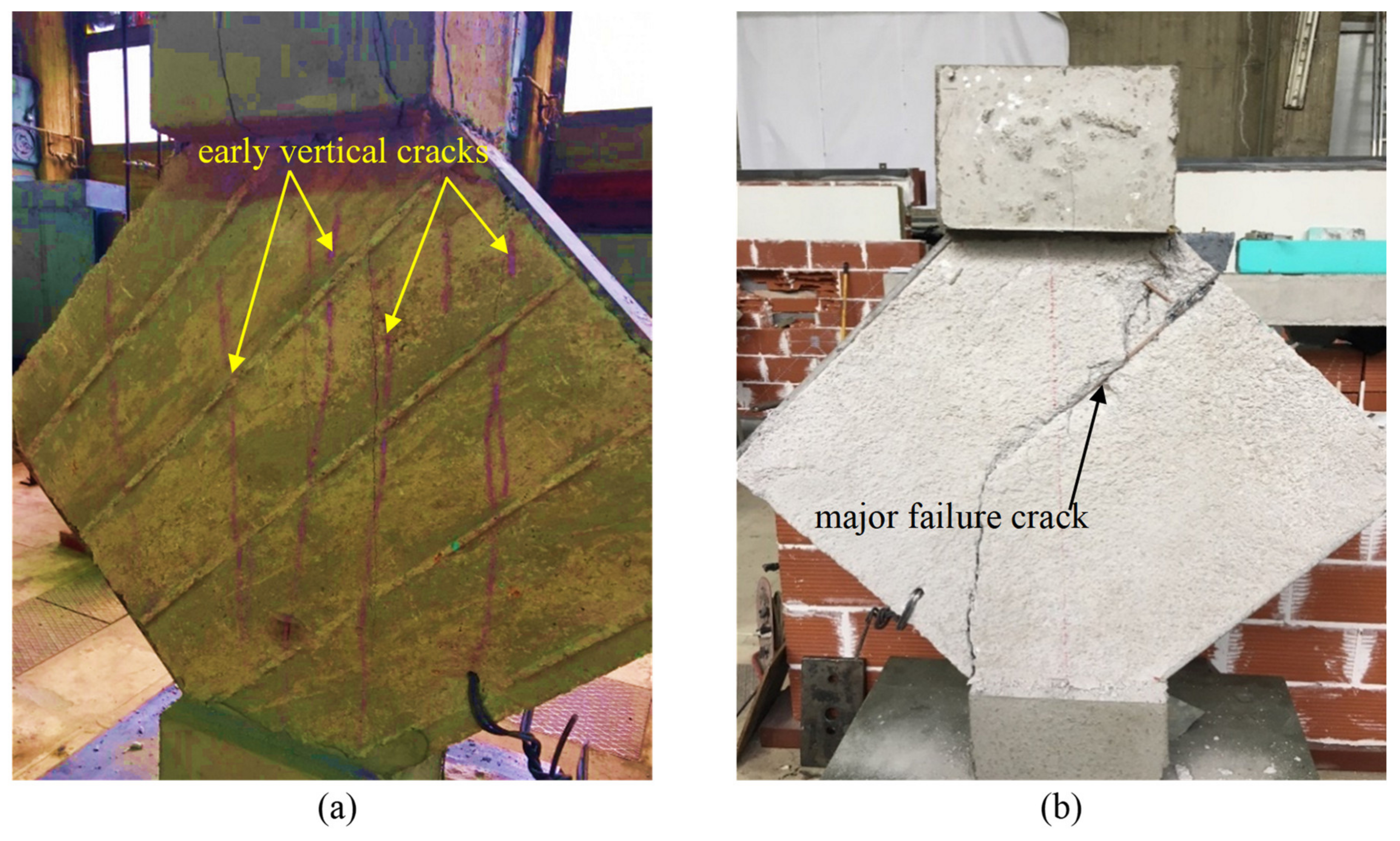
  • The PCSP-3 specimens under diagonal compression failed with a major vertical crack propagating from the upper to the bottom corner. The two tested specimens failed in a ductile manner owing to the embedded shear connectors and steel mesh reinforcement which provided adequate confinement on the concrete and prevented a sudden failure mode. The maximum shear resistance was recorded at 3.0 MPa.
  • Two steel joints specimens with different bolt arrangements were tested under cyclic loading. Both failed similarly due to welding cracks between the end plate and the upper flange of the steel column. The results denoted no significant difference in the response of both investigated joints as it was limited by the weld’s failure.
  • The failure mechanism of the full-scale PCSP-ISF model under in-plane cyclic loading was a combination of plastic hinges in the steel bolted joints and diagonal cracks in the concrete panels.
  • The structural behaviour of the concrete panels of the PCSP-ISF is highly dependent on the stiffness and strength of the shear bars welded to the respective SHSs.
  • The beneficial role of the well-detailed horizontal and vertical reinforcement and the SHS members, along with the previously mentioned embedded shear connectors provided an adequate restraint against diagonal compression failure up to 14 mm of the imposed displacement.
  • The displacement ductility factor of the PCSP-ISF was calculated as equal to μδ =3.9, which is satisfactory but quite underestimated. The average equivalent viscous damping ratio achieved during testing was 13%, demonstrating the capability of a high dissipation capacity. The initial stiffness reduced about 80%, and the highest loss occurred at low levels of the displacement amplitudes.
  • The “equivalent diagonal strut” model was utilised to evaluate the shear capacity of the PCSP-ISF. The theoretical shear capacity was found to be 12% higher than the corresponding experimental one, which is a good approximation, due to the complex structural behaviour of the PCSP-ISF model.
  • By that presented here, the structural system in the composite buildings can be satisfied by an optimal structural dynamic performance, which is an important sustainability aspect of resistance and economy due to the importance of the seismic hazard to the safety of buildings in many areas worldwide.
  • Τhe described series of laboratory tests is a source of corresponding confirmation of the multiple numerical tests for the obtaining of a reliable and sustainable prefabricated building. The steel columns at the end of the longitudinal direction of the basic PSPF-ISF model include location in the transversal local axis directions of their cross-sections. So, with the connection in the longitudinal as well as in the transversal direction of the panels, where the upper beam is prefabricated, construction is made easy and reliable by joining them with the previously placed steel columns on the concrete base. The lower part of the panel is connected with an additional in situ concrete layer and shear added bars from both sides. The capacity of the three bolted joints of the panel to each side of the respective columns (beam-to-column joint and wall-to-column joints) satisfies the design purposes of evaluating the total test program of the project, where the PCSP-2 specimen tests were very significant.
It is concluded that the PCSP-ISF model experienced a satisfactory seismic performance, and thereby, it could be successfully employed in typical future building applications in earthquake-prone regions. Nonetheless, further experimental, theoretical, and numerical investigation has been in progress [15,24,45] during this research, and more is needed to extend the results of this experimental campaign for a more comprehensive understanding of the non-linear response of the system.

Author Contributions

Formal analysis, K.K.; Funding acquisition, K.T. and T.I.; Investigation, E.G., T.N. and K.K.; Methodology, T.N. and K.K.; Project administration, K.T.; Resources, K.T. and T.I.; Supervision, K.K.; Validation, T.I.; Writing—original draft, E.G.; Writing—review & editing, T.N. and K.K. All authors have read and agreed to the published version of the manuscript.

Funding

This research was funded by the European Regional Development Fund of the European Union and Greek national funds through the Operational Program Competitiveness, Entrepreneurship, and Innovation, under the call RESEARCH—CREATE—INNOVATE, grand number T1EDK-03042.

Institutional Review Board Statement

Not applicable.

Informed Consent Statement

Not applicable.

Data Availability Statement

Not applicable.

Acknowledgments

The experimental work has been conducted within the research project SUstainable Preconstructed Innovative Module, which has been co-financed by the European Regional Development Fund of the European Union and Greek national funds through the Operational Program Competitiveness, Entrepreneurship, and Innovation, under the call RESEARCH—CREATE—INNOVATE (project code: T1EDK-03042). The authors are grateful to the technicians of the Laboratory for Strength of Materials and Structures of the Department of Civil Engineering at the Aristotle University of Thessaloniki for their valuable assistance. Moreover, high appreciation is expressed to the Company “Thedoros Iliadis Prefabricated Constructions” for the supplying of the test specimens. The prefabricated wall system described in this paper is part of the Greek Patent Application No. 20210100921, filed on 30 December 2021 [19], and of the European Patent Office Application No. ΕΡ 22165414.8, filed on 30 March 2022 [20].

Conflicts of Interest

The authors declare no conflict of interest.

References

  1. Federation Internationale du Beton (FIB). Precast Concrete in Mixed Construction, State-of-Art Report; Bulletin 43; FIB: Lausanne, Switzerland, 2002. [Google Scholar]
  2. Holden, T.; Restrepo, J.; Mander, J.B. Seismic performance of precast reinforced and prestressed concrete walls. J. Struct. Eng. 2003, 129, 286–296. [Google Scholar] [CrossRef]
  3. Benayoune, A.; Samad, A.; Abang Ali, A.A.; Trikha, D.N. Response of pre-cast reinforced composite sandwich panels to axial loading. Constr. Build. Mater. 2007, 21, 677–685. [Google Scholar] [CrossRef]
  4. Hamid, N.H.; Mander, J.B. Lateral seismic performance of multipanel precast SHS core walls. J. Struct. Eng. 2010, 136, 795–804. [Google Scholar] [CrossRef]
  5. Pavese, A.; Bournas, D.A. Experimental assessment of the seismic performance of a prefabricated concrete structural wall system. Eng. Struct. 2011, 33, 2049–2062. [Google Scholar] [CrossRef]
  6. Kabir, M.Z.; Rahai, A.R.; Nassira, Y. Non-linear response of combined system. 3D wall panels and bending steel frame subjected to seismic loading. WIT Trans. Built Environ. 2006, 85, 705–714. [Google Scholar]
  7. Guo, Z.; Yuan, Y. Experimental study of steel plate composite shear wall units under cyclic load. Int. J. Steel Struct. 2015, 15, 515–525. [Google Scholar] [CrossRef]
  8. Jiang, L.Q.; Zheng, H.; Hu, Y. Experimental seismic performance of steel- and composite steel-panel wall strengthened steel frames. Arch. Civ. Mech. 2017, 17, 520–534. [Google Scholar] [CrossRef]
  9. Hu, Y.; Zhang, D.; Chen, Y. Seismic behavior of concrete-filled double-skin steel tube/moment-resisting frames with beam-only-connected precast reinforced concrete shear walls. Arch. Civ. Mech. 2019, 19, 967–980. [Google Scholar] [CrossRef]
  10. Zhu, J.S.; Guo, Y.L.; Wang, M.Z.; Yang, X.; Pi, Y.L. Seismic performance of concrete-infilled double steel corrugated-plate walls: Experimental research. Eng. Struct. 2020, 215, 110601. [Google Scholar] [CrossRef]
  11. Dall’Asta, A.; Leoni, G.; Zona, A.; Hoffmeister, B.; Bigelow, H.; Degée, H.; Braham, C.; Bogdan, T.; Salvatore, W.; Morelli, F.; et al. Innovative Hybrid and Composite Steel-Concrete Structural Solutions for Building in Seismic Area; Final Report, EUR 26932 EN; European Commission: Brussels, Belgium, 2015.
  12. Huang, Q.; Guo, Z.; Kuang, J.S. Designing infilled reinforced concrete frames with the ‘strong frame-weak infill’ principle. Eng. Struct. 2016, 123, 341–353. [Google Scholar] [CrossRef]
  13. Amran, Y.H.M.; El-Zeadani, M.; Lee, Y.H.; Lee, Y.Y.; Murali, G.; Feduik, R. Design innovation, efficiency and applications of structural insulated panels: A review. Structures 2020, 27, 1358–1379. [Google Scholar] [CrossRef]
  14. Tsikaloudaki, K.; Theodosiou, T.; Giarma, C.; Kontoleon, K.; Aravantinos, D.; Tsoka, S.; Tsirigoti, D.; Karaoulis, A.; Chastas, P. Building a new sustainable preconstructed building element. IOP Conf. Ser. Earth Environ. Sci. 2020, 410, 012115. [Google Scholar] [CrossRef]
  15. Nikolaidis, T.; Vitalis, T.; Baniotopoulos, C.C. Analysis of Thermal and Buckling Behaviour of Double-Shell Composite Wall Exposed to Fire. In Proceedings of the 12th International Congress on Mechanics (HSTAM), Thessaloniki, Greece, 22–25 September 2019. [Google Scholar]
  16. EN 10080:2005; Steel for the Reinforcement of Concrete. Weldable Reinforcing Steel. General European Committee for Standardization (CEN): Brussels, Belgium, 2005.
  17. EN 1992-1-1; Eurocode 2: Design of Concrete Structures. Part 1-1: General Rules and Rules for Buildings. European Committee for Standardization (CEN): Brussels, Belgium, 2004.
  18. EN ISO 898-3:2018; Mechanical Properties of Fasteners Made of Carbon Steel and Alloy Steel. Flat Washers with Specified Property Classes. European Committee for Standardization (CEN): Brussels, Belgium, 2018.
  19. Aristotle University of Thessaloniki ELKE; Iliadis, T.; Tsikaloudaki, K.; Nikolaidis, T.; Katakalos, K.; Theodosiou, T. Prefabricated Composite Structural Wall System and Method of Assemply and Manufacturing Thereof. Greek Patent 20210100921; Application No. 246-0004466610, 30 December 2021. (In Greek). [Google Scholar]
  20. Aristotle University of Thessaloniki ELKE; Iliadis, T.; Tsikaloudaki, K.; Nikolaidis, T.; Katakalos, K.; Theodosiou, T. Prefabricated Composite Structural Wall System and Method of Assemply and Manufacturing Thereof. EU Patent EP22165414; Application No. EP 22165414.8, 30 March 2022. [Google Scholar]
  21. EN 206-2013; Concrete—Specification, Performance, Production and Conformity. European Committee for Standardization (CEN): Brussels, Belgium, 2013.
  22. ASCE. Specifications for the Design and Construction of Composite Slabs; ASCE: New York, NY, USA, 1984. [Google Scholar]
  23. Gara, F.; Ragni, L.; Roia, D.; Dezi, L. Experimental tests and numerical modelling of wall sandwich panels. Eng. Struct. 2012, 37, 193–204. [Google Scholar] [CrossRef]
  24. Nikolaidis, T.; Ziakis, I.; Papaevangelou, S.; Katakalos, K.; Baniotopoulos, C.C. Numerical and Experimental Study of Steel Beam to Column Connections under Dynamic Loading in Low-Rise Prefabricated Modular Buildings. In Proceedings of the 3rd Coordinating Engineering for Sustainability and Resilience (CESARE ’22), Irbid, Jordan, 6–9 May 2022. [Google Scholar]
  25. EN 1993-1-1; Eurocode 3: Design of Steel Structures. Part 1–1: Design of Joints. European Committee for Standardization (CEN): Brussels, Belgium, 2005.
  26. EN 1994-1-1; Eurocode 4: Design of Composite Steel and Concrete Structures. Part 1-1: General Rules and Rules for Buildings. European Committee for Standardization (CEN): Brussels, Belgium, 2004.
  27. EN ISO 6892-1:2009; Metallic Materials—Tensile Testing—Part 1: Method of Test at Room Temperature. European Committee for Standardization (CEN): Brussels, Belgium, 2009.
  28. Krawinkler, H. Loading histories for cyclic tests in support of performance assessment of structural components. In Proceedings of the 3rd International Conference on Advances in Experimental Structural Engineering, San Francisco, CA, USA, 15–16 October 2009. [Google Scholar]
  29. EN 1993-1-8; Eurocode 3: Design of Steel Structures. Part 1–8: General Rules and Rules for Buildings. European Committee for Standardization (CEN): Brussels, Belgium, 2005.
  30. ATC-24. Guidelines for Cyclic Seismic Testing of Components of Steel Structures for Buildings; Report No. ATC-24; Applied Technology Council: Redwood City, CA, USA, 1992. [Google Scholar]
  31. Cosenza, E.; Manfredi, G.; Ramasco, R. The use of damage functionals in earthquake engineering: A comparison between different methods. Earthq. Eng. Struct. Dyn. 1993, 22, 855–868. [Google Scholar] [CrossRef]
  32. Erduran, E.; Yakut, A. Drift based damage functions for reinforced concrete columns. Comput. Struc. 2004, 82, 121–130. [Google Scholar] [CrossRef]
  33. Krawinkler, H.; Medina, R.; Alavi, B. Seismic drift and ductility demands and their dependence on ground motions. Eng. Struct. 2003, 25, 637–653. [Google Scholar] [CrossRef]
  34. Mansouri, A.; Marefat, M.S.; Khanmohammadi, M. Experimental evaluation of seismic performance of lowshear strength masonry infills with openings in reinforced concrete frames with deficient seismic details. Struct. Tall Spec. Build. 2013, 23, 1190–1210. [Google Scholar] [CrossRef]
  35. Medina, R.A.; Krawinkler, H. Evaluation of drift demands for the seismic performance assessment of frames. J. Struct. Eng. ASCE 2005, 131, 1003–1013. [Google Scholar] [CrossRef]
  36. EN 1998-1:2004; Eurocode 8: Design of Structures for Earthquake Resistance. General Rules, Seismic Actions and Rules for Buildings. European Committee for Standardization (CEN): Brussels, Belgium, 2004.
  37. Park, R. Ductility evaluation from laboratory and analytical testing. In Proceedings of the 10th World Conference on Earthquake Engineering (10WCEE), Tokyo, Japan, 2–9 August 1988; pp. 605–616. [Google Scholar]
  38. FEMA 356; Prestandard and Commentary for the Seismic Rehabilitation of Buildings (FEMA356). Federal Emergency Management Agency: Washington, DC, USA, 2000.
  39. Miranda, E.; Bertero, V. Evaluation of strength reduction factors for earthquake-resistant design. Earthq. Spectra EERI 1994, 10, 357–379. [Google Scholar] [CrossRef]
  40. Chopra, A.K. Dynamics of Structures: Theory and Applications to Earthquake Engineering; Prentice-Hall: Englewood Cliffs, NJ, USA, 1995. [Google Scholar]
  41. Markulak, D.; Radić, I.; Sigmund, V. Cyclic testing of single bay steel frames with various types of masonry infill. Eng. Struct. 2013, 51, 267–277. [Google Scholar] [CrossRef]
  42. Tasnimi, A.A.; Mohebkhah, A. Investigation on the behavior of brick-infilled steel frames with openings; experimental and analytical approaches. Eng. Struct. 2011, 33, 968–980. [Google Scholar] [CrossRef]
  43. FEMA 306; Evaluation of Earthquake Damaged Concrete and Masonry Wall Buildings. Federal Emergency Management Agency: Washington, DC, USA, 1998.
  44. ASCE/SEI 41-13; Seismic Evaluation and Retrofit of Existing Buildings. American Society of Civil Engineers (ASCE): Reston, VA, USA, 2014.
  45. Nikolaidis, T.; Koukouli, N.; Maliokas, A.; Baniotopoulos, C.C. Stability Investigations in Composite Steel-Concrete Walls for Restoration Purposes to Enhance Structural and Sustainable Design. IOP Conf. Ser. Earth Environ. Sci. 2020, 410, 012109. [Google Scholar] [CrossRef] [Green Version]
Figure 1. Geometrical details of the PCSP-1 cross-section [19,20].
Energies 15 03458 g001
Figure 2. Experimental setup of compression test of representative concrete cylindrical sample of the test specimens.
Energies 15 03458 g002
Figure 3. Experimental setup of the three-point bending test on PCSP-1 specimen.
Energies 15 03458 g003
Figure 4. Load versus mid-span displacement curve of PCSP-1 specimen.
Energies 15 03458 g004
Figure 5. Failure mechanism of PCSP-1 specimen under three-point bending: (a) flexural micro-cracks on the tensile concrete panel and (b) wide flexural crack on the tensile concrete panel.
Energies 15 03458 g005
Figure 6. Experimental setup of concentric axial compression on PCSP-2 specimen.
Energies 15 03458 g006
Figure 7. Effective stress versus strain curves of the PCSP-2a and PCSP-2b specimens.
Energies 15 03458 g007
Figure 8. Failure mechanism of PCSP-2a specimen under concentric axial compression.
Energies 15 03458 g008
Figure 9. Experimental setup of PCSP-3a subjected to diagonal compression test.
Energies 15 03458 g009
Figure 10. Effective shear stress versus strain curves of the PCSP-3a and PCSP-3b specimens.
Energies 15 03458 g010
Figure 11. Failure mechanism of PCSP-3a specimen under diagonal compression: (a) vertical cracks on the concrete panels at early loading stages and (b) major failure crack on the concrete panels.
Energies 15 03458 g011
Figure 12. Three-dimensional schematic view of the investigated steel bolted joints: (a) JL-4 bolted joint specimen and (b) JL-6 bolted joint specimen.
Energies 15 03458 g012
Figure 13. Two-dimensional schematic view of JL-4 bolted steel joint specimen configuration with geometrical details of the steel connecting plates of the JL-4 and JL-6 specimens.
Energies 15 03458 g013
Figure 14. Experimental setup for (a) the JL-4 and (b) the JL-6 steel bolted joint specimen.
Energies 15 03458 g014
Figure 15. Applied loading scheme on the bolted joint specimens.
Energies 15 03458 g015
Figure 16. Failure mechanism of the steel bolted joint specimens: (a) JL-4 specimen and (b) JL-6 specimen.
Energies 15 03458 g016
Figure 17. Moment versus rotation curves of the steel bolted joint specimens: (a) JL-4 specimen and (b) JL-6 specimen.
Energies 15 03458 g017
Figure 18. Skeleton curves of the steel bolted joint specimens.
Energies 15 03458 g018
Figure 19. Front schematic view of the PCSP-ISF model configuration [19,20].
Energies 15 03458 g019
Figure 20. Top schematic view of the PCSP-ISF configuration.
Energies 15 03458 g020
Figure 21. View of the of the PCSP-ISF model and its test support conditions.
Energies 15 03458 g021
Figure 22. Experimental setup of the PCSP-ISF model and instrumentation of the in-plane cyclic loading test.
Energies 15 03458 g022
Figure 23. Applied loading scheme on the PCSP-ISF test model.
Energies 15 03458 g023
Figure 24. Load versus displacement curve of the tested PCSP-ISF model.
Energies 15 03458 g024
Figure 25. Plastic damage on the lower joint of the tested PCSP-ISF model.
Energies 15 03458 g025
Figure 26. Determination of equivalent hysteretic damping ratio.
Energies 15 03458 g026
Figure 27. Equivalent viscous damping ratio versus displacement curve of the tested PCSP-ISF model.
Energies 15 03458 g027
Figure 28. Stiffness versus displacement curve of the tested PCSP-ISF model.
Energies 15 03458 g028
Table 1. Summary of the experimental campaign.
StructureType of ExperimentNo. of Experiments
PCSP-1Three-point bending1
PCSP-2Concentric axial compression2
PCSP-3Diagonal compression2
steel bolted jointsCyclic loading2
PCSP-ISF modelIn-plane cyclic loading1
Table 2. Obtained hysteresis characteristics of the tested PCSP-ISF model.
Hysteresis CharacteristicsLoading Direction
PositiveNegativeAverage
Fy [kN]285.3283.7284.5
δy [mm]4.24.14.2
Fmax [kN]399.4396.8398.1
δmax [mm]16.016.016.0
Fu [kN]399.4 396.8 398.1
δu [mm]16.016.0 16.0
Θ [%]0.70.70.7
Kinit [kN/mm]130.5 122.7 126.6
μδ3.83.93.9
Publisher’s Note: MDPI stays neutral with regard to jurisdictional claims in published maps and institutional affiliations.

