
Method of Evaluation of Materials Wear of Cylinder-Piston Group of Diesel Engines in the Biodiesel Fuel Environment

 , , , ,
Abstract
1. Introduction
- Kinematic viscosity at 100 °C-ν100 for fresh oil,
- Kinematic viscosity at 100 °C-ν100 for used oil (in the time of its replacement),
- Oil working time-vehicle mileage from the time of the last change.
2. Materials and Methods
3. Results and Discussion
- -
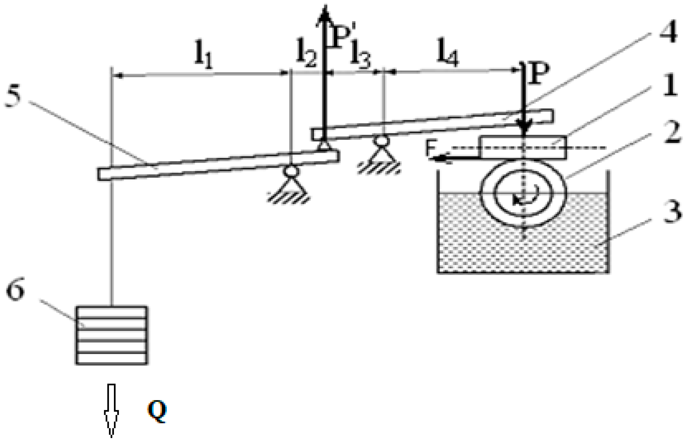
- To substantiate a technique of laboratory research;
- -
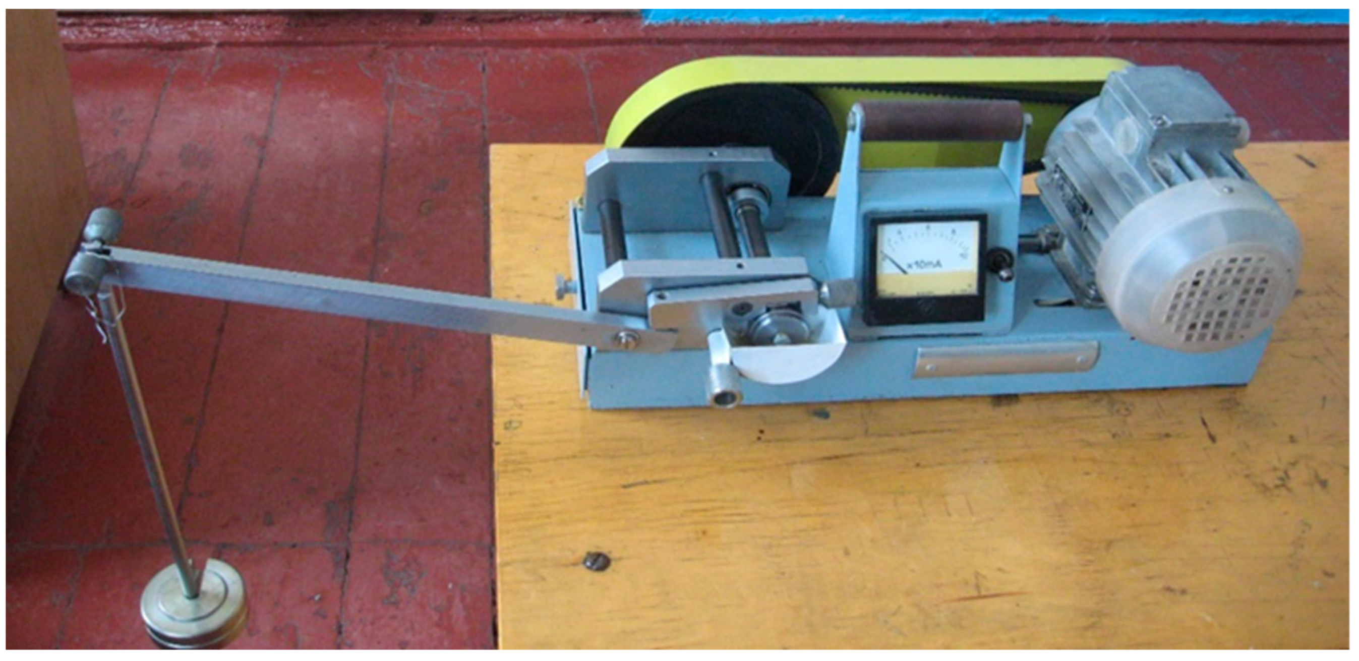
- To make a choice of laboratory equipment for tribotechnical research;
- -
- To carry out the comparative description of biofuel influence on tribological properties of the materials of cylinder-piston group of diesel engines.
4. Conclusions
Author Contributions
Funding
Institutional Review Board Statement
Informed Consent Statement
Data Availability Statement
Conflicts of Interest
References
- The European Commission. Innovation at the service of sustainable growth: The bioeconomy for Europe. Comm. Commun. COM 2012, 60, 3. [Google Scholar]
- Jonek-Kowalska, I.; Berny, D.; Płaza, G. Assessment of biofuels competitiveness in the current technological, market and legal conditions. In Scientific Papers of the Silesian University of Technology; Series: Organization and Management; Silesian University of Technology; Faculty of Organization and Management: Gliwice, Poland, 2016; pp. 142–152. [Google Scholar]
- Gralak, K. Bioeconomy as an area of intelligent regional specialization. Eur. Policies Financ. Mark. 2015, 14, 65–73. [Google Scholar]
- The European Commission. Europe 2020: A strategy for smart, sustainable and inclusive growth. Comm. Commun. COM 2020, 2010, 13. [Google Scholar]
- Gołębiewski, J. Sustainable Bioeconomy-Potential and Development Factors. In Proceedings of the IX Congress of Polish Economists, Warszawa, Poland, 9 July 2013; p. 2. [Google Scholar]
- The Knowledge Based Bio-Economy (KBBE) in Europe: Achievements and Challenges. 2010. Available online: http://www.bioeconomy.net/reports/files/KBBE_2020_BE_presidency.pdf (accessed on 10 January 2022).
- Maciejczak, M.; Hofreiter, K. How to define bioeconomy? Assoc. Agric. Agribus. Econ. Ann. Sci. 2013, 15, 244–246. [Google Scholar]
- Pajewski, T. Bioeconomy as a strategic element of sustainable agriculture. Assoc. Agric. Agribus. Econ. Ann. Sci. 2014, 16, 179–184. [Google Scholar]
- Kozłowska, A.; Kozłowski, K.; Skawiński, W.; Kapka-Skrzypczak, L. Effect of pollutants emissions from biofuels on the envi-ronment and human health. Hygeia Public Health 2020, 55, 45–55. [Google Scholar]
- Leme, D.M.; Grummt, T.; de Oliveira, D.P.; Sehr, A.; Renz, S.; Reinel, S.; Ferraz, E.R.A.; de Marchi, M.R.R.; Machado, M.C.; Zocolo, G.J.; et al. Genotoxicity assessment of water soluble fractions of biodiesel and its diesel blends using the Salmonella assay and the in vitro MicroFlow® kit (Litron) assay. Chemosphere 2012, 86, 512–520. [Google Scholar] [CrossRef]
- Berny, D.; Wandzich, D.; Płaza, G. Challenges for the biofuel sector in the light of the developing bioeconomy. Sci. Pap. Sil. Univ. Technol. Organ. Manag. 2015, 79, 41–55. [Google Scholar]
- Biernat, K. Second generation biofuels. Studia Ecol. Bioethcae 2007, 5, 281–294. [Google Scholar] [CrossRef]
- Polish Standard PN-EN 14214; Liquid Petroleum Products-Fatty Acid Methyl Esters (FAME) for Use in Compression-Ignition (Diesel) Car Engines and Heating Applications-Requirements and Test Methods. Polish Committee for Standardization: Warszawa, Poland, 2015.
- Galwas-Zakrzewska, M.; Makles, Z. The influence of biocomponents on the composition of engine exhaust gases. Work Saf. 2013, 11, 10–13. [Google Scholar]
- Rauch, R.; Hrbek, J.; Hofbauer, H. Biomass gasification for synthesis gas production and applications of the syngas. Wiley Interdiscip. Rev. Energy Environ. 2013, 3, 343–362. [Google Scholar] [CrossRef]
- Rąbalski, M. Biopaliwa Płynne. Available online: https://energia360.pl/biomasa,ac149/biopaliwa-plynne,1711 (accessed on 15 February 2017).
- Górski, W.; Jabłońska, M.M. Dimethyl ether-universal, ecological fuel of the 21st century. NAFTA-GAZ 2012, ROK LXVIII, 631–641. [Google Scholar]
- Marcinkowski, D.; Gracz, W. Production of biofuels and bioproducts. In the Monograph-Production of Biogas in a Biomass Refinery, Taking into Account the Aspects of Biogas Plant Operation; Wawrzyniak, A., Ed.; Institute of Technology and Life Sciences: Falenty, Poland; Publishing House ITP: Warsaw, Poland, 2020. [Google Scholar]
- Roszkowski, A. Biodiesel in the EU and Poland-current conditions and prospects. Agric. Eng. Probl. 2012, 20, 65–78. [Google Scholar]
- Malina, R. HEFA and F-T jet fuel cost analyses. In Proceedings of the Sustainable Alternative Fuels Cost Workshop (MIT), Cambridge, MA, USA, 27 November 2012. [Google Scholar]
- Picazo-Espinosa, R.; González-López, J.; Manzanera, M. Bioresources for Third-Generation Biofuels. Available online: www.intechopen.com/download/pdf/17479 (accessed on 12 May 2012).
- Błaszak, M. The use of algae for energy: Current state and perspectives. Arch. Waste Manag. Environ. Prot. 2014, 16, 141–152. [Google Scholar]
- Szymczyk, E. The State of Research and Prospects for the Implementation of Technology for the Production of Fuel Bioethanol from Lignocellulosic Raw Materials. Ph.D. Thesis, Faculty of Energy and Fuels, AGH University of Science and Technology Stanisława Staszica, Kraków, Poland, 2008. [Google Scholar]
- Owczuk, M. Biodiesel and environmental protection. In Studia Ecologiae et Bioethicae; Institute of Fuels and Renewable Energy: Warsaw, Poland, 2006; Volume 4, pp. 351–356. [Google Scholar]
- Li, H.; Shi, L.; Deng, K. Development of turbocharging system for diesel engines of power generation application at different altitudes. J. Energy Inst. 2016, 89, 755–765. [Google Scholar] [CrossRef]
- Shelar, M.N.; Bagade, S.D.; Kulkarni, G.N. Energy and Exergy Analysis of Diesel Engine Powered Trigeneration Systems. Energy Proc. 2016, 90, 27–37. [Google Scholar] [CrossRef]
- Seifi, M.R.; Hassan-Beygi, S.R.; Ghobadian, B.; Desideri, U.; Antonelli, M. Experimental investigation of a diesel engine power, torque and noise emission using water–diesel emulsions. Fuel 2016, 166, 392–399. [Google Scholar] [CrossRef]
- Mikulski, M.; Wierzbicki, S. Numerical investigation of the impact of gas composition on the combustion process in a du-al-fuel compression-ignition engine. J. Nat. Gas Sci. Eng. 2016, 31, 525–537. [Google Scholar] [CrossRef]
- Wasilewski, J.; Krzaczek, P. Emission of toxic compounds from combustion of biodiesel: A report from studies. Przem. Chem. 2014, 93, 343–346. [Google Scholar] [CrossRef]
- Hoseini, S.S.; Najafi, G.; Ghobadian, B.; Mamat, R.; Sidik, N.A.C.; Azmi, W.H. The effect of combustion management on diesel engine emissions fueled with biodiesel-diesel blends. Renew. Sustain. Energy Rev. 2017, 73, 307–331. [Google Scholar] [CrossRef]
- Asokan, M.; Prabu, S.S.; Kamesh, S.; Khan, W. Performance, combustion and emission characteristics of diesel engine fuelled with papaya and watermelon seed oil bio-diesel/diesel blends. Energy 2017, 145, 238–245. [Google Scholar] [CrossRef]
- Hossain, F.M.; Rainey, T.; Ristovski, Z.; Brown, R.J. Performance and exhaust emissions of diesel engines using microalgae FAME and the prospects for microalgae HTL biocrude. Renew. Sustain. Energy Rev. 2018, 82, 4269–4278. [Google Scholar] [CrossRef]
- Canakci, M.; Sanli, H. Biodiesel production from various feedstocks and their effects on the fuel properties. J. Ind. Microbiol. Biotechnol. 2008, 35, 431–441. [Google Scholar] [CrossRef]
- Rehan, M.; Gardy, J.; Demirbas, A.; Rashid, U.; Budzianowski, W.M.; Pant, D.; Nizami, A.S. Waste to biodiesel: A preliminary assessment for Saudi Arabia. Bioresour. Technol. 2018, 250, 17–25. [Google Scholar] [CrossRef]
- Sander, A.; Košćak, M.A.; Kosir, D.; Milosavljević, N.; Vuković, J.P.; Magić, L. The influence of animal fat type and purification conditions on biodiesel quality. Renew. Energy 2018, 118, 752–760. [Google Scholar] [CrossRef]
- Matwijczuk, A.; Zając, G.; Kowalski, R.; Kachel-Jakubowska, M.; Gagoś, M. Spectroscopic Studies of the Quality of Fatty Acid Methyl Esters Derived from Waste Cooking Oil. Pol. J. Environ. Stud. 2017, 26, 2643–2650. [Google Scholar] [CrossRef]
- Marcinkowski, D.; Rukowicz, B.; Golimowski, W.; Czechlowski, M.; Krzaczek, P.; Piekarski, W. Effect of selected depressants on cold filter plugging point for methyl esters obtained from transesterification of waste vegetable and animal fats. Przem. Chem. 2017, 96, 1927–1930. [Google Scholar] [CrossRef]
- Krzaczek, P.; Rybak, A.; Bochniak, A. The impact of selected biofuels on the performance parameters of the Common Rail power system in the utility engine. In Proceedings of the 10th International Scientific Conference on Aeronautics, Automotive and Railway Engineering and Technologies, Sozopol, Bulgaria, 15–17 September 2018. [Google Scholar] [CrossRef]
- Cucui, G.; Ionescu, C.A.; Goldbach, I.R.; Coman, M.D.; Marin, E.L.M. Quantifying the Economic Effects of Biogas Installa-tions for Organic Waste from Agro-Industrial Sector. Sustainability 2018, 10, 2582. [Google Scholar] [CrossRef]
- Pillay, A.; Molki, A.; Elkadi, M.; Manuel, J.; Bojanampati, S.; Khan, M.; Stephen, S. Real-Time Study of Noxious Gas Emissions and Combustion Efficiency of Blended Mixtures of Neem Biodiesel and Petrodiesel. Sustainability 2013, 5, 2098–2107. [Google Scholar] [CrossRef]
- Basavarajappa, Y.H.; Banapurmath, N.R.; Pradeep, G.; Vinod, R.; Yaliwal, V. Performance and emission characteristics of a CNG-Biodiesel dual fuel operation of a single cylinder four stroke CI engine. IOP Conf. Ser. Mater. Sci. Eng. 2018, 376, 012028. [Google Scholar] [CrossRef]
- Golimowski, W.; Krzaczek, P.; Marcinkowski, D.; Gracz, W.; Wałowski, G. Impact of Biogas and Waste Fats Methyl Esters on NO, NO2, CO, and PM Emission by Dual Fuel Diesel Engine. Sustainability 2019, 11, 1799. [Google Scholar] [CrossRef]
- Wang, Q.; Ge, M.; Guo, X.; Li, Z.; Huang, A.; Yang, F.; Guo, R. Hydrophobic poly(ionic liquid)s as “two-handed weapons”: Maximizing lipase catalytic efficiency in transesterification of soybean oil toward biodiesel. Appl. Catal. A Gen. 2021, 626, 118350. [Google Scholar] [CrossRef]
- Zhao, R.; Yang, X.; Li, M.; Peng, X.; Wei, M.; Zhang, X.; Yang, L.; Li, J. Biodiesel preparation from Thlaspi arvense L. seed oil utilizing a novel ionic liquid core-shell magnetic catalyst. Ind. Crop. Prod. 2021, 162, 113316. [Google Scholar] [CrossRef]
- Malekghasemi, S.; Kariminia, H.-R.; Plechkova, N.K.; Ward, V.C. Direct transesterification of wet microalgae to biodiesel using phosphonium carboxylate ionic liquid catalysts. Biomass-Bioenergy 2021, 150, 106126. [Google Scholar] [CrossRef]
- Yu, J.; Wang, Y.; Sun, L.; Xu, Z.; Du, Y.; Sun, H.; Li, W.; Luo, S.; Ma, C.; Liu, S. Catalysis Preparation of Biodiesel from Waste Schisandra chinensis Seed Oil with the Ionic Liquid Immobilized in a Magnetic Catalyst: Fe3O4@SiO2@[C4mim]HSO4. ACS Omega 2021, 6, 7896–7909. [Google Scholar] [CrossRef] [PubMed]
- Naushad, M.; Ahamad, T.; Khan, M.R. Fabrication of magnetic nanoparticles supported ionic liquid catalyst for transesterification of vegetable oil to produce biodiesel. J. Mol. Liq. 2021, 330, 115648. [Google Scholar] [CrossRef]
- Changmai, B.; Rano, R.; Vanlalveni, C.; Rokhum, L. A novel Citrus sinensis peel ash coated magnetic nanoparticles as an easily recoverable solid catalyst for biodiesel production. Fuel 2021, 286, 119447. [Google Scholar] [CrossRef]
- Zhang, P.; Liu, P.; Fan, M.; Jiang, P.; Haryono, A. High-performance magnetite nanoparticles catalyst for biodiesel production: Immobilization of 12-tungstophosphoric acid on SBA-15 works effectively. Renew. Energy 2021, 175, 244–252. [Google Scholar] [CrossRef]
- Roy, M.; Mohanty, K. Valorization of de-oiled microalgal biomass as a carbon-based heterogeneous catalyst for a sustainable biodiesel production. Bioresour. Technol. 2021, 337, 125424. [Google Scholar] [CrossRef]
- Akkarawatkhoosith, N.; Tongtummachat, T.; Kaewchada, A.; Jaree, A. Non-catalytic and glycerol-free biodiesel production from rice bran oil fatty acid distillate in a microreactor. Energy Convers. Manag. X 2021, 11, 100096. [Google Scholar] [CrossRef]
- Jung, S.; Jung, J.-M.; Lee, K.H.; Kwon, E.E. Biodiesels from non-catalytic transesterification of plant oils and their performances as aviation fuels. Energy Convers. Manag. 2021, 244, 114479. [Google Scholar] [CrossRef]
- Sukharev, E.A. The operational reliability of the machines. In Theory, Methodology, Modeling: A Tutorial; NUVHP: Rivne, Ukraine, 2006; p. 192. [Google Scholar]
- Voitov, V.A.; Datsenko, M.S.; Karnaukh, M.V. Features of operation of fuel equipment of agricultural diesels witht heuse of biofuels. Mach. Technol. Agro-Ind. Complex 2010, 1, 13–18. [Google Scholar]
- Devianin, S.N.; Markov, V.A.; Semenov, V.G. Vegetable Oils and Fuels Based on Them for Diesel Engines; Publishing Center of State University of Agricultural Science, Moscow State University: Moscow, Russia, 2007; p. 340. [Google Scholar]
- Molodyk, M.V. Scientific Bases of the System of Maintenance and Repair of Machines in Agriculture; CODE: Kirovograd, Ukraine, 2009; p. 180. [Google Scholar]
- Chernovol, M.I. (Ed.) Reliability of Agricultural Machinery, 2nd ed.; Reworked, and add; National University of Bioresources and Natural Resources of Ukraine: Kirovograd, Ukraine, 2010; p. 168. [Google Scholar]
- Tziourtzioumis, D.; Demetriades, L.; Zogou, O.; Stamatelos, A. Experimental investigation of the effect of a B70 biodiesel blend on a common-rail passenger car diesel engine. Proc. Inst. Mech. Eng. Part D J. Automob. Eng. 2009, 223, 685–701. [Google Scholar] [CrossRef]
- Lin, B.F.; Huang, J.H.; Huang, D.Y. Experimental study of the effects of vegetable oil methyl ester on DI diesel engine per-formance characteristics and pollutant emissions. Fuel 2009, 88, 1779–1785. [Google Scholar] [CrossRef]
- Nagy, A.L.; Knaup, J.; Zsoldos, I. A friction and wear study of laboratory aged engine oil in the presence of diesel fuel and oxymethylene ether. Tribol.-Mater. Surf. Interfaces 2018, 13, 20–30. [Google Scholar] [CrossRef]
- Singh, P.; Goel, V.; Chauhan, S.R. Effects of dual biofuel approach for total elimination of diesel on injection system by reciprocatory friction monitor. Proc. Inst. Mech. Eng. Part J J. Eng. Tribol. 2018, 232, 1068–1076. [Google Scholar] [CrossRef]
- Zhuravel, D.P. Methodology for assessing the reliability of mobile agricultural machinery during operation on different types of fuels and lubricants. In Bulletin of Sumy National Agrarian University; Sumy National Agrarian University: Sumy, Ukraine, 2016; pp. 66–71. [Google Scholar]
- Zhuravel, D.P. Increasing the durability of functional systems of agricultural machinery using biofuels and lubricants. In Scientific Bulletin of the National University of Life and Environmental Sciences of Ukraine; Series: Machinery and Energy of Agro-Industrial Complex. K. Sumy National Agrarian University: Sumy, Ukraine, 2018; pp. 279–292. [Google Scholar]
- Zhuravel, D.P. Modeling of the process of wear of precision pairs of fuel systems of mobile equipment during operation on biodiesel. In Works of TSATU; National University of Bioresources and Natural Resources of Ukraine: Kirovograd, Ukraine, 2018; pp. 105–118. [Google Scholar]
- Zhuravel, D.P. Improving the efficiency of mobile agricultural machinery by ensuring the optimal composition of blended biodiesel fuels. In Scientific Bulletin of TSATU: Electronic Scientific Professional Publication; TSATU: Melitopol, Ukraine, 2018; Issue 8, Item 2; pp. 91–107. [Google Scholar]
- Baberg, A.; Freidhager, M.; Mergel, H.; Schmidt, K. Aspekte der Kolbenmaterialwahl bei Dieselmotoren. Mot. Z. 2012, 73, 964–969. [Google Scholar] [CrossRef]
- Blümm, M.; Baberg, A.; Dörnenburg, F.; Leitzmann, D. Innovative Schaftbeschichtungen für Otto- und Dieselmotorkolben. Mot. Z. 2016, 77, 54–59. [Google Scholar] [CrossRef]
- Deuss, T.; Ehnis, H.; Rose, R.; Künzel, R. Reibleistungsmessun gen am Befeuerten Dieselmotor-Potenziale der Kolbengruppe. Mot. Z. 2010, 71, 326–330. [Google Scholar]
- Mahle GmbH, Piston and Engine Testing; Typesetting: Klementz Publishing Services, Freiburg, Printing Company; AZ Druck und Datentechnik: Berlin/Stuttgart, Germany, 2012; ISBN 978-3-8348-1590-3; Available online: https://link.springer.com/content/pdf/bfm%3A978-3-8348-8662-0%2F1.pdf (accessed on 1 May 2022).
- Wróblewski, E.; Iskra, A.; Babiak, M. Minimizing the wear of elements of the piston-cylinder group. In Operation and Tests; BUS-ES: Poland, 2017; p. 1137. [Google Scholar]
- Nadolny, K.; Chmielewski, Z.; Nikoniuk, J. Non-invasive method of assessing the wear of cylinder liners of a diesel engine. In Operation and Reliability; 2005; pp. 30–37. Available online: http://docplayer.pl/7170823-Spis-tresci-nauka-i-technika.html (accessed on 1 May 2022).
- Łuczak, A.; Mazur, T. Physical Aging of Machine Elements; WNT: Warsaw, Poland, 1981. [Google Scholar]
- Nadolny, K. Reliability Problems of Operational Changes in the Quality of Engine Lubricating Oils; Dissertations No. 164; Poznań University of Technology: Poznań, Poland, 1985. [Google Scholar]
- Niewczas, A.; Gil, L.; Ignaciuk, P. Analysis of the Tribological Wear Processes of the Elements of the Injection System of a Com-Pression-Ignition Engine Fueled with Vegetable Oils; Szczodrak, M., Kamińska, P., Konieczna, A., Eds.; WSEI Scientific Journals Series: Transport and Information Technology, 1, 1/2011, 5–22; Poland Innovatio Press Scientific Publishing House of the University of Economics and Innovation: Lublin, Poland, 2011; ISSN 2084-8005. [Google Scholar]
- Nowiński, E.; Giemza, B.; Domańsk, M. Thickness measurement of thin oil layers in triboelectrical phenomenon aspect. J. KONBiN 2015, 27, 87–98. [Google Scholar] [CrossRef][Green Version]
- Kulczycki, A.; Wachal, A. Energy problems of boundary layer durability. Tribology 1985, 16, 21–23. [Google Scholar]
- Napadłek, W. Tribological models of cooperation piston-piston rings-cylinder liner of the combustion engine. Tribology 2009, 5, 135–145. [Google Scholar]
- Georgogianni, K.G.; Kontominas, M.G.; Pomonis, P.J.; Avlonitis, D.; Gergis, V. Conventional and in situ transesterification of sunflower seed oil for the production of biodiesel. Fuel Process. Technol. 2008, 89, 503–509. [Google Scholar] [CrossRef]
- Boltianskyi, B.; Sklyar, R.; Boltyanska, N.; Boltianska, L.; Dereza, S.; Grigorenko, S.; Syrotyuk, S.; Jakubowski, T. The Process of Operation of a Mobile Straw Spreading Unit with a Rotating Finger Body-Experimental Research. Processes 2021, 9, 1144. [Google Scholar] [CrossRef]
- Dobrzański, L.A.; Dobrzańska-Danikiewicz, A.D. Changes in the structure and surface properties of engineering materials as a result of exploitation. Subsection: 8.1. General classification of changes in the structure and surface properties of engineering materials as a result of exploitation. Open Access Libr. 2011, 5, 368–416. [Google Scholar]
- Płaza, S.; Margielewski, L.; Celichowski, G. Introduction to Tribology and Tribochemistry; Publishing House of the University of Lodz: Lodz, Poland, 2005; ISBN 83-7171-909-4. [Google Scholar]
- Hadam, U.; Zakroczymski, T. Stress and strain in hydrogen embrittlement of metals. Prot. Against Corros. 2010, 4–5, 239–241. [Google Scholar]
- Pietkun-Greber, I.; Janka, R.M. Effect of hydrogen on metals and alloys. Proc. ECOpole 2010, 4, 471–476. [Google Scholar]
- Łunarska, E. Hydrogen corrosion in industrial installations and pipelines. Its monitoring and prevention. In Proceedings of the Mater. IV National Corrosion Conference KOROZJA’93, IChF PAN, Warsaw, Poland, 1993; pp. 8–13. [Google Scholar]
- Zakroczymski, T. Modification of metal surfaces to prevent hydrogen corrosion. Prot. Against Corros. 2006, 4, 99–102. [Google Scholar]
- Chen, J.-M.; Wu, J.-K. Hydrogen diffusion through copper-plated AISI 4140 steels. Corros. Sci. 1992, 33, 657–666. [Google Scholar] [CrossRef]
- Flis, J. Penetration of hydrogen into steel with a modified surface layer. Prot. Against Corros. 2000, 7, 177–179. [Google Scholar]
- Zakroczymski, T. Methods of preventing the absorption of hydrogen by metals. Prot. Against Corros. 2005, 4, 90–93. [Google Scholar]
- CORDIS. Available online: https://cordis.europa.eu/article/id/92756-hydrogen-transport-in-metals-understood/pl (accessed on 1 April 2022).
- Kračun, A.T.; Zobov, E.V.; Morar, V.E.; Bruchis, M.M.; Kračun, S.V. Issledovanie vlijanija tverdogo smazočnogo materiała na protivoiznosnye, protivozadirnye i antifrikcionnye svojstva plastičnych smazok. Trenie Iznos 1981, 2, 856–863. [Google Scholar]
- Krawiec, S. Compositions of Plastic and Solid Lubricants in the Process of Friction of Steel Machine Nodes; Publishing House of the Wrocław University of Technology: Wrocław, Poland, 2011; ISBN 978-83-7493-658-3. [Google Scholar]
- Nowak, J. Influence of Batch Leads on the Microstructure and Selected Properties of Ductile Iron Smelted at a Given Superheat-Ing Temperature. Ph.D. Thesis, Faculty of Foundry Engineering, AGH University of Science and Technology Stanisława Staszica, Kraków, Poland, 2019. Available online: https://winntbg.bg.agh.edu.pl/rozprawy2/11464/full11464.pdf (accessed on 1 April 2022).
- Zander, D. Hydrogen Gas Pressure Regulation to 16 Bar Using Aluminum Materials. Available online: https://www.medenus.de/files/upload/downloads/wasserstoff/medenus-regulacja-cisnienia-gazu-wodorowego.pdf (accessed on 1 April 2022).
- Niekurzak, M. Determining the Unit Values of the Allocation of Greenhouse Gas Emissions for the Production of Biofuels in the Life Cycle. Energies 2021, 14, 8394. [Google Scholar] [CrossRef]
- Niekurzak, M. The Potential of Using Renewable Energy Sources in Poland Taking into Account the Economic and Ecological Conditions. Energies 2021, 14, 7525. [Google Scholar] [CrossRef]
- Adams, P.W.; McManus, M.C. Characterisation and variability of greenhouse gas emissions from biomethane production via anaerobic digestion of maize. J. Clean. Prod. 2019, 218, 529–542. [Google Scholar] [CrossRef]
- Olczak, P.; Matuszewska, D.; Kryzia, D. “Mój Prąd” as an example of the photovoltaic one off grant program in Poland. Energy Policy J. 2020, 23, 123–138. [Google Scholar] [CrossRef]
- Niekurzak, M.; Kubińska-Jabcoń, E. Analysis of the return on investment in solar collectors on the example of a household: The case of Poland. Front. Energy Res. 2021, 9, 660140. [Google Scholar] [CrossRef]
- Ledakowicz, S.; Krzystek, L. Wykorzystanie fermentacji metanowej w utylizacji odpadów przemysłu rolno-spozywczego. Biotechnologia 2005, 3, 165–183. [Google Scholar]
- Ardolino, F.; Parrillo, F.; Arena, U. Biowaste-to-biomethane or biowaste-to-energy? An LCA study on anaerobic digestion of organic waste. J. Clean. Prod. 2018, 174, 462–476. [Google Scholar] [CrossRef]
- Kalina, J.; Skorek, J.; Cebula, J.; Latocha, L. Pozyskiwanie i energetyczne wykorzystanie biogazu rolniczego. Gospod. Paliwami Energią 2003, 12, 14–19. [Google Scholar]
- Ge, J.; Choi, N. Soot Particle Distribution and Regulated and Unregulated Emissions of a Diesel Engine Fueled with Palm Oil Biodiesel Blends. Energies 2020, 13, 5736. [Google Scholar] [CrossRef]
- Ge, J.C.; Kim, H.Y.; Yoon, S.K.; Choi, N.J. Reducing volatile organic compound emissions from diesel engines using canola oil biodiesel fuel and blends. Fuel 2018, 218, 266–274. [Google Scholar] [CrossRef]
- Ge, J.C.; Kim, H.Y.; Yoon, S.K.; Choi, N.J. Optimization of palm oil biodiesel blends and engine operating parameters to im-prove performance and PM morphology in a common rail direct injection diesel engine. Fuel 2020, 260, 116326. [Google Scholar] [CrossRef]
- Voytovych, I.; Malovanyy, M.; Zhuk, V.; Mukha, O. Facilities and problems of processing organic wastes by family- type bio-gas plants in Ukraine. J. Water Land Dev. 2020, 45, 185–189. [Google Scholar] [CrossRef]
- Wałowski, G. Development of biogas and biorafinery systems in Polish rural communities. J. Water Land Dev. 2021, 49, 156–168. [Google Scholar] [CrossRef]
- Awogbemi, O.; Kallon, D.V.V.; Onuh, E.I.; Aigbodion, V.S. An Overview of the Classification, Production and Utilization of Biofuels for Internal Combustion Engine Applications. Energies 2021, 14, 5687. [Google Scholar] [CrossRef]
- Directive 2009/28/EC of the European Parliament and of the Council of 23 April 2009. On the Promotion of the Use of Energy from Renewable Sources Amending and Subsequently Repealing Directives 2001/77/EC and 2003/30/EC. Available online: https://eur-lex.europa.eu/legal-content/EN/TXT/PDF/?uri=CELEX:32009L0028 (accessed on 1 April 2022).
- Directive 2012/27/EU of the European Parliament and of the Council of 25 October 2012. On Energy Efficiency, Amending Directives 2009/125/EC and 2010/30/EU and Repealing Directives 2004/8/EC and 2006/32/EC. Available online: https://eur-lex.europa.eu/legal-content/EN/NIM/?uri=celex:32012L0027 (accessed on 1 April 2022).


| Substrate | Production-Group | Production-Subgroup | Process Use Net Calorific Value | Process Use | Net Calorific Value | |
|---|---|---|---|---|---|---|
| First generation biofuels | ||||||
| Arable crops such as cereals, corn, sugar cane, rape, sugar beets | Bioethanol (alcoholic fermentation) | Bioethanol (BioEtOH) understood as conventional ethanol [11] | Hydrolysis and fermentation of sugars | Car engines | 27 MJ/kg | |
| Pure Vegetable Oils (PVO) | Cold pressing and extraction of oilseeds | Only in suitably modified diesel engines [12] | 37 MJ/kg | |||
| Biodiesel (1st generation) esterification of vegetable oils: –rapeseed, –soy, –palm, –sunflower | Biodiesel being methyl esters (Fatty Acid Methyl Esters-FAME) and ethyl (Fatty Acid Ethylesters-FAEE) higher fatty acids of oilseeds, including rapeseed (Rapeseed Methyl Ester-RME, REE) | Cold pressing, extraction and transesterification | diesel fuel; Fuel with an appropriate additive quantity and quality of the biocomponent [13] | 37 MJ/kg 40.1 MJ/kg | ||
| biodiesel, being methyl and ethyl esters | Transesterification post-cooking oil waste and animal fats | |||||
| Biogas | Cleaning of landfill or agricultural biogas; | Cogeneration | 20–26 MJ/m3 | |||
| Second generation biofuels | ||||||
| Organic cellulose residues, derived from plants that can be grown in wastelands or polluted areas (straw, energy willow, miscanthus) | Bioethanol, obtained as a result of advanced hydrolysis and fermentation processes of cellulosic and lignocellulosic biomass (excluding foodstuffs) | Ethyl alcohol (BioEt) and ethyl-tert-butyl esters (Ethyl-Tert-Butyl Ether–ETBE) obtained from BioEt; HTU-diesel fuel (Hydro Thermal Upgrading) obtained in the process of depolymerization of waste organic raw materials at high temperature, the so-called pyrolytic hydrothermal decomposition of biomass; | Extraction, pyrolysis, synthesis, synthetic hydrolysis as well as hydrotreatment | Additive to motor gasoline, as bio-additive E%, e.g., E95 containing 95% gasoline and 5% ethanol [12,14]. | 27 MJ/kg | |
| Synthetic biofuels, which are products of biomass processing waste and lignocellulosic by gasification and appropriate synthesis into liquid components fuel (Biomass to Liquid-BtL [15] | Biohydrogen | Gasification of lignocellulose and synthesis of the resulting products, or a biochemical process | Production: –thermal energy, –electricity in fuel cells, –intrinsic motor fuel | 43 MJ/kg | ||
| hydrocarbon fuels for ignition engines self-acting obtained by the Fischer-Tropsch processes | Synthetic hydrocarbon fuels | Gasification | BtL –liquid fractions and mixtures obtained from biomass | 44 MJ/kg | ||
| Biomethanol; | It is chemically identical to standard methanol. | Dry distillation of plant biomass, consisting in drying and grinding the raw material and introducing the obtained pulp into the reactor and gasification | A fuel replacement for aviation and sport spark ignition engines and as a solvent [16]. | 20 MJ/kg | ||
| Mixtures Higher alcohols and dimethyl ether (bio-DME); | Dimethyl ether is produced from synthesis gas (CO + H2) by two methods: indirect synthesis (via methanol) and direct synthesis [17] | Car transport | 28 MJ/kg | |||
| Dimethylfuran (DMF) | A solvent used in many industrial sectors, in particular chemical | –dyes, laboratory chemicals, –cleaning products, –adhesives and sealants | 28 MJ/kg | |||
| Biogas and the biomass liquefaction process, during which it is first gasified | Biogas | Biological breakdown of organic materials in an anaerobic atmosphere known as anaerobic breakdown | The gas obtained is then used to produce fuels | 17–25 MJ/m3 | ||
| SNG (Synthetic Natural Gas)–synthetically obtained natural gas; | The power-to-gas process allows the captured CO2 to be utilized and transformed into a usable fuel which is SNG | |||||
| Non-food oils [18]: –cooking oils, –oils from inedible plants, –jatropha, jojoba | Biodiesel (2nd generation) | HVO–Hydrotreated Vegetable Oil–hydrothermal catalysis, hydrogenation, hydrotreatment (co-hydrogenation) of components from oil processing petroleum and vegetable oils and/or animal fats | Under combustion conditions of partially homogeneous mixtures (ang. Partially Premixed Compression Ignition) | 40.1 MJ/kg | ||
| Biomass | HTU–Hydrothermal Upgrading–pyrolytic hydrothermal decomposition of biomass with water at 300–350 °C and 100–180 bar pressure within 5–15 min [19] | Jet fuel with hydrotreated esters or acids fatty [20] | ||||
| chemical catalysis-acidic and alkaline, at what sour technologies are less efficient (slower) but require lower temperatures (up to 60 °C), making them less energy-intensive (alkaline catalysis requires approx. 80 °C) [19] | Renewable jet fuel [20] | |||||
| Enzymatic with the use of lipases (enzymes that break down fats) produced by certain strains of bacteria [21] | Jet fuel from fermentation advanced [20] | |||||
| Third generation biofuels | ||||||
| Algae-reserve substances: starch and lipids, and building substances: protein contained in cells of some species. | Biodiesel (3rd generation) | A source of several types of renewable biofuels, incl. biodiesel, biohydrogen and biomethane | 30 times more energy than from 1st or 2nd generation biofuels [22] | Hydrogen production servant to power fuel cells [23] | 120 MJ/kg | |
| Material | Chemical Composition, % | Hardness Rockwella, H, HRC | |||||||
|---|---|---|---|---|---|---|---|---|---|
| C | Si | Mn | Cr | P | S | Ni | Cu | ||
| Steel 45 | 0.42–0.50 | 0.17–0.37 | 0.50–0.80 | − | 0.035 | 0.04 | − | − | 58.0 |
| Cast iron SCh 20 | 3.0–3.3 | 1.3–1.7 | 0.8–1.2 | 0.3 | 0.3 | 0.15 | 0.5 | − | 18.0 |
| Chemical Composition, % | |||||||||
| Pb | Zn | Sn | Ti | Cu | Al | Si | Fe | ||
| Bronze Br OCS 5-5-5 | 4.0–6.0 | 4.0–6.0 | 4.0–6.0 | − | other | 6.0 | |||
| Aluminum A0 | − | 0.08 | − | 0.03 | 0.02 | 99.0 | 0.50 | 0.50 | 3.0 |
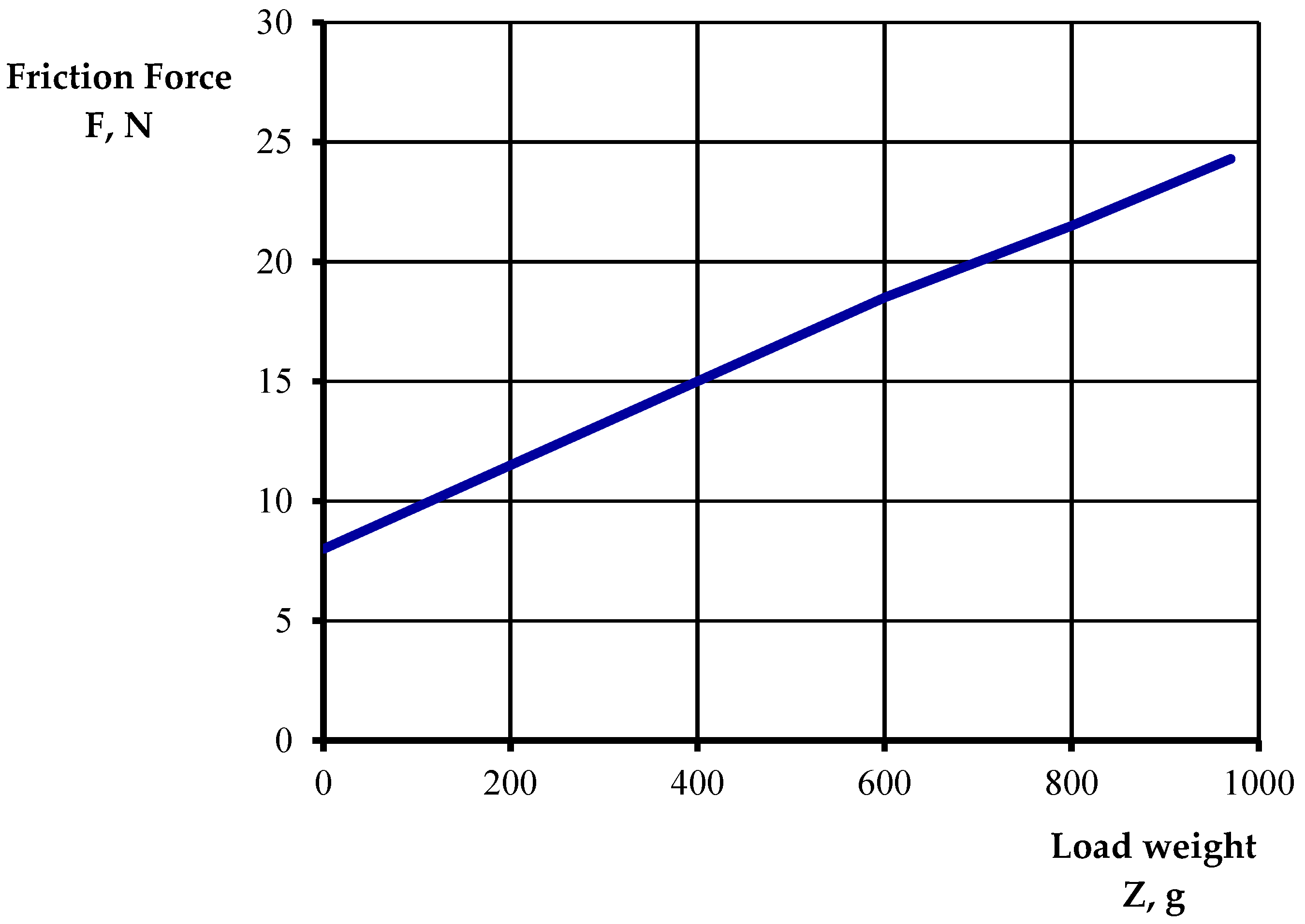
| Sample | Friction Force F, N | The Force on Working Pair P, N | Coefficients of Friction μ |
|---|---|---|---|
| Without load | 8 | 21.05 | 0.38 |
| 1 load * | 16 | 42.10 | 0.37 |
| 2 loads | 24 | 61.35 | 0.39 |
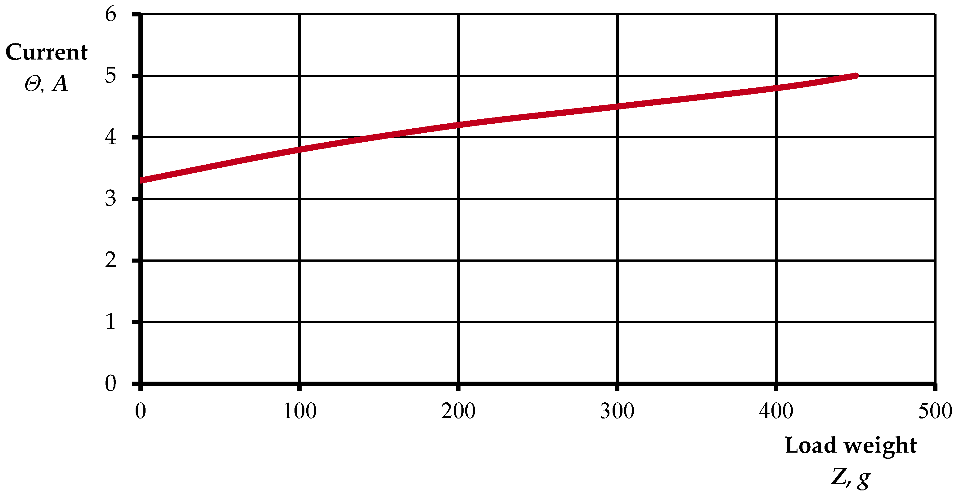
| Indicator | Value | ||||
|---|---|---|---|---|---|
| Weight of the load Z, g | 0 | 50 | 100 | 200 | 480 |
| Current (ammeter reading) Θ, A | 3.25 | 3.5 | 3.75 | 4.15 | 4.95 |
| Material | B, mm | Friction Path E, m | |||||||||||||
|---|---|---|---|---|---|---|---|---|---|---|---|---|---|---|---|
| 75 | 150 | 225 | 300 | 375 | 450 | 525 | |||||||||
| Current (Ammeter Reading) and the Width of the Crater | |||||||||||||||
| Θ, A | b mm | Θ, A | b mm | Θ, A | b mm | Θ, A | b mm | Θ, A | b mm | Θ, A | b mm | Θ, A | b mm | ||
| Bronze Br OCS 5-5-5 | 7.8 | 2.5 | 2 | 2.6 | 2.4 | 2.8 | 2.6 | 2.0 | 2.7 | 1.5 | 2.7 | 1.7 | 2.7 | 1.7 | 2.8 |
| Cast iron SCh 20 | 6.7 | 2 | 0.8 | 2 | 1 | 2 | 1.1 | 2 | 1.2 | 2 | 1.3 | 2 | 1.4 | 2 | 1.5 |
| Steel 45 | 7.0 | 3 | 0.5 | 2.9 | 0.6 | 2.8 | 0.7 | 2.9 | 0.8 | 2.9 | 0.85 | 2.9 | 0.9 | 2.9 | 1.0 |
| Aluminum A0 | 8.0 | 2 | 2.2 | 2 | 2.8 | 2 | 3.1 | 2 | 3.4 | 2 | 3.6 | 2 | 3.7 | 2 | 3.8 |
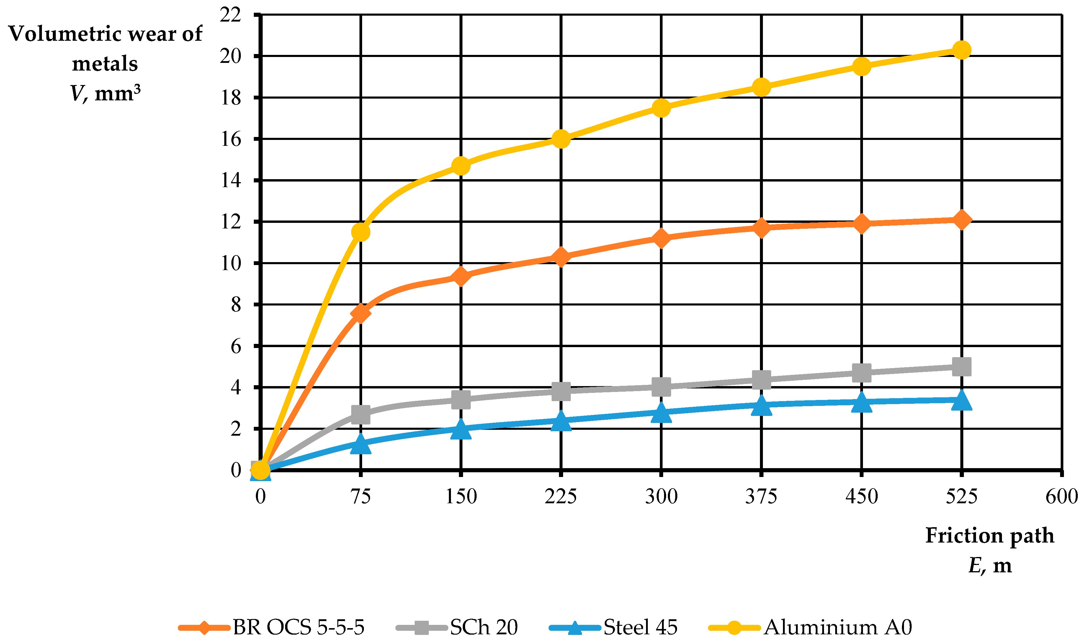
| Material | Friction Path E, m | ||||||
|---|---|---|---|---|---|---|---|
| 75 | 150 | 225 | 300 | 375 | 450 | 525 | |
| Consumption of the Volume of the Material V, mm3 | |||||||
| Bronze Br OCS 5-5-5 | 7.57 | 9.36 | 10.3 | 11.2 | 11.7 | 11.9 | 12.1 |
| Cast iron SCh 20 | 2.68 | 3.4 | 3.8 | 4.02 | 4.36 | 4.7 | 5.0 |
| Steel 45 | 1.30 | 2.0 | 2.4 | 2.8 | 3.15 | 3.3 | 3.4 |
| Aluminium A0 | 11.5 | 14.7 | 16.0 | 17.5 | 18.5 | 19.5 | 20.3 |
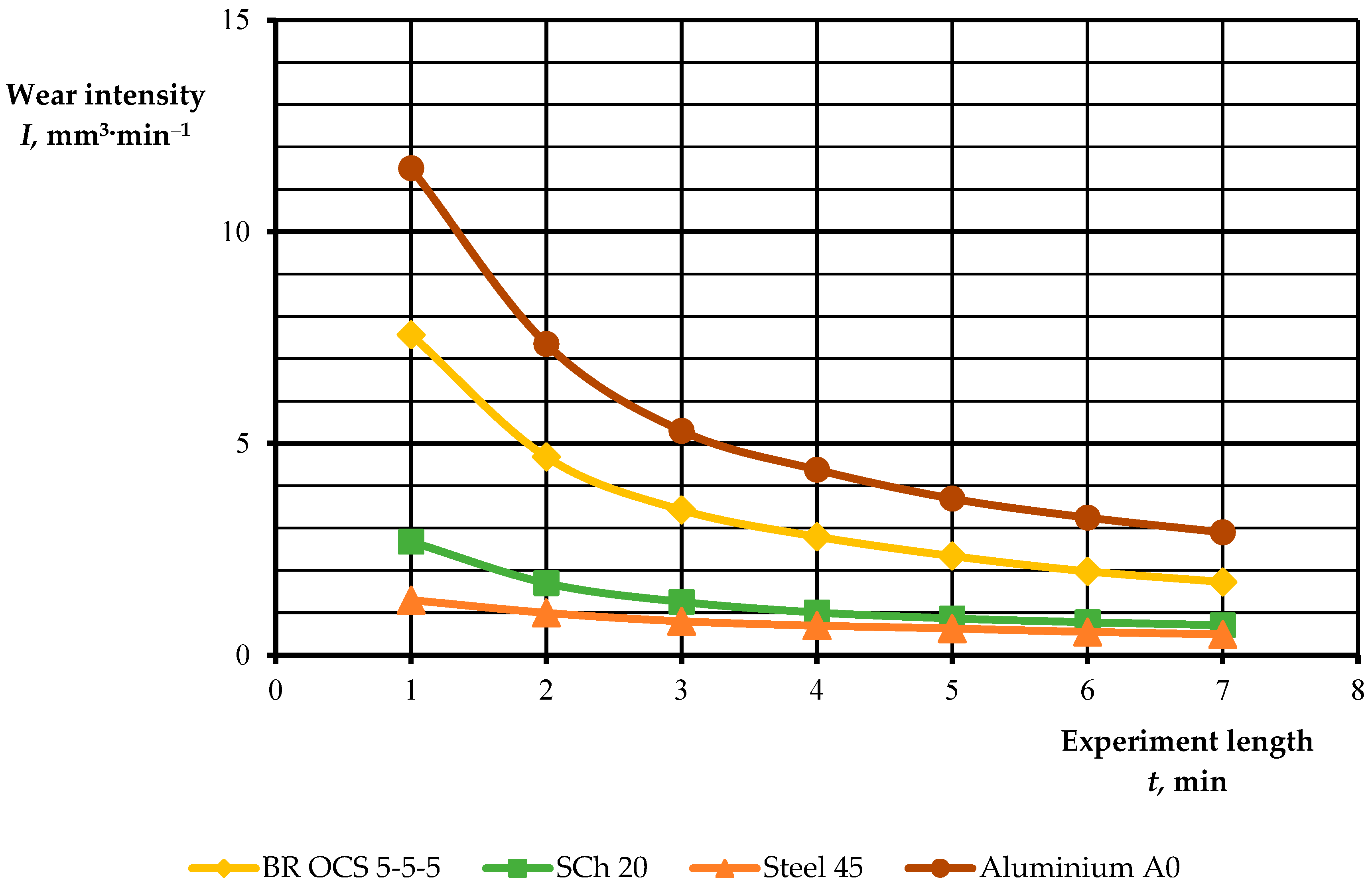
| Material | Experiment Length t, min | ||||||
|---|---|---|---|---|---|---|---|
| 1 | 2 | 3 | 4 | 5 | 6 | 7 | |
| Wear Intensity I, mm3·min−1 | |||||||
| Bronze BR OCS 5-5-5 | 7.57 | 4.68 | 3.43 | 2.8 | 2.34 | 1.98 | 1.73 |
| Cast iron SCh 20 | 2.68 | 1.7 | 1.26 | 1.01 | 0.87 | 0.78 | 0.71 |
| Steel 45 | 1.3 | 1.0 | 0.8 | 0.7 | 0.63 | 0.55 | 0.49 |
| Aluminum A0 | 11.5 | 7.35 | 5.3 | 4.38 | 3.7 | 3.25 | 2.9 |
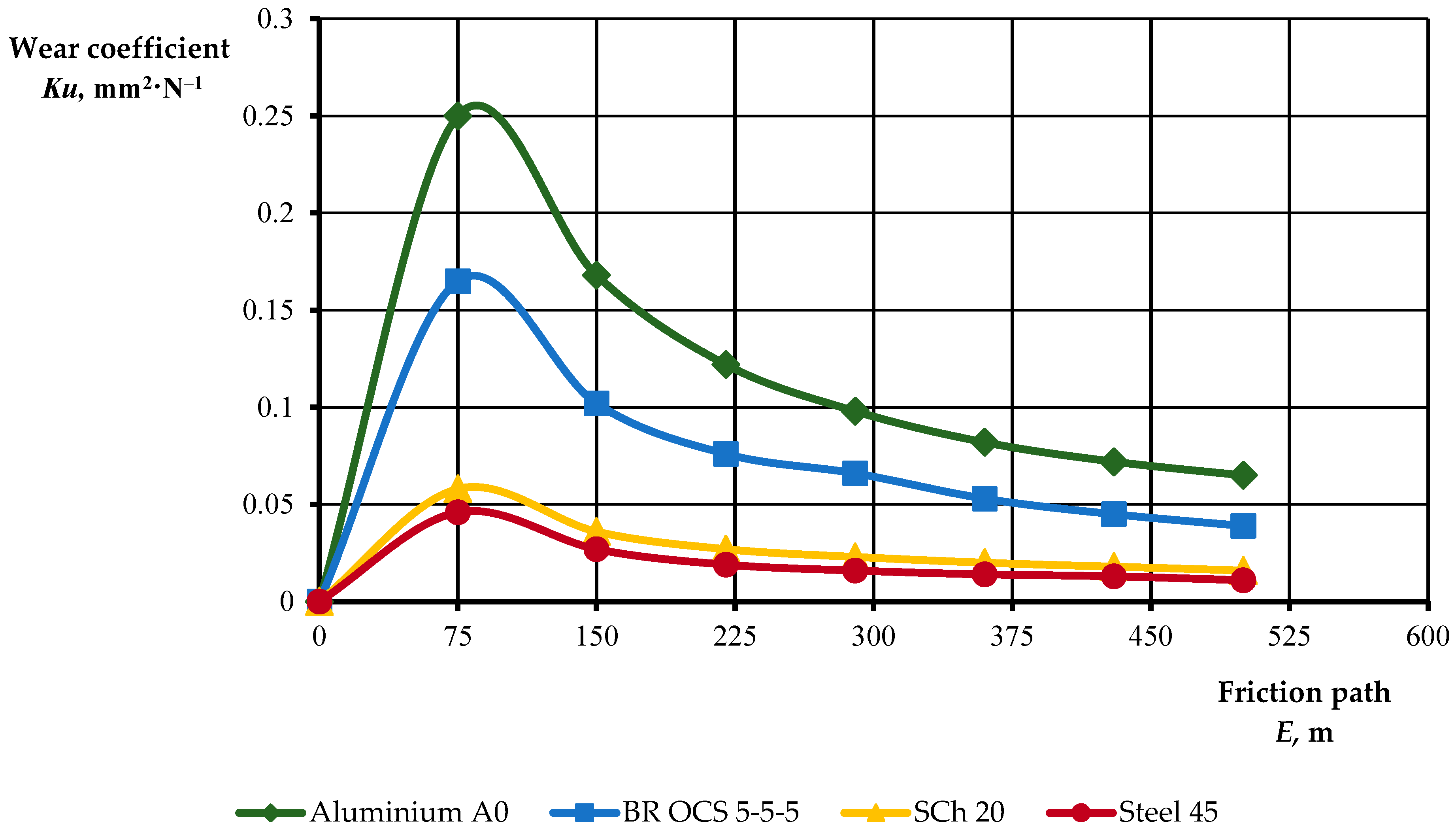
| Material | Friction Path E, m | ||||||
|---|---|---|---|---|---|---|---|
| 75 | 150 | 220 | 290 | 360 | 430 | 500 | |
| Wear Coefficients Ku, mm2·N−1 | |||||||
| Aluminum A0 | 0.250 | 0.168 | 0.122 | 0.098 | 0.082 | 0.072 | 0.065 |
| Bronze BR OCS 5-5-5 | 0.165 | 0.102 | 0.076 | 0.066 | 0.053 | 0.045 | 0.039 |
| Cast iron SCh 20 | 0.058 | 0.036 | 0.027 | 0.023 | 0.020 | 0.018 | 0.016 |
| Steel 45 | 0.046 | 0.027 | 0.019 | 0.016 | 0.014 | 0.013 | 0.011 |
Publisher’s Note: MDPI stays neutral with regard to jurisdictional claims in published maps and institutional affiliations. |
© 2022 by the authors. Licensee MDPI, Basel, Switzerland. This article is an open access article distributed under the terms and conditions of the Creative Commons Attribution (CC BY) license (https://creativecommons.org/licenses/by/4.0/).
Share and Cite
Kapłan, M.; Klimek, K.; Maj, G.; Zhuravel, D.; Bondar, A.; Lemeshchenko-Lagoda, V.; Boltianskyi, B.; Boltianska, L.; Syrotyuk, H.; Syrotyuk, S.; et al. Method of Evaluation of Materials Wear of Cylinder-Piston Group of Diesel Engines in the Biodiesel Fuel Environment. Energies 2022, 15, 3416. https://doi.org/10.3390/en15093416
Kapłan M, Klimek K, Maj G, Zhuravel D, Bondar A, Lemeshchenko-Lagoda V, Boltianskyi B, Boltianska L, Syrotyuk H, Syrotyuk S, et al. Method of Evaluation of Materials Wear of Cylinder-Piston Group of Diesel Engines in the Biodiesel Fuel Environment. Energies. 2022; 15(9):3416. https://doi.org/10.3390/en15093416
Chicago/Turabian StyleKapłan, Magdalena, Kamila Klimek, Grzegorz Maj, Dmytro Zhuravel, Andrii Bondar, Viktoriia Lemeshchenko-Lagoda, Boris Boltianskyi, Larysa Boltianska, Hanna Syrotyuk, Serhiy Syrotyuk, and et al. 2022. "Method of Evaluation of Materials Wear of Cylinder-Piston Group of Diesel Engines in the Biodiesel Fuel Environment" Energies 15, no. 9: 3416. https://doi.org/10.3390/en15093416
APA StyleKapłan, M., Klimek, K., Maj, G., Zhuravel, D., Bondar, A., Lemeshchenko-Lagoda, V., Boltianskyi, B., Boltianska, L., Syrotyuk, H., Syrotyuk, S., Konieczny, R., Filipczak, G., Anders, D., Dybek, B., & Wałowski, G. (2022). Method of Evaluation of Materials Wear of Cylinder-Piston Group of Diesel Engines in the Biodiesel Fuel Environment. Energies, 15(9), 3416. https://doi.org/10.3390/en15093416