Article

Transient Response Characteristics of Metal Oxide Arrester under High-Altitude Electromagnetic Pulse

State Key Laboratory of Intense Pulsed Radiation Simulation and Effect, Northwest Institute of Nuclear Technology, Xi’an 710024, China
*
Author to whom correspondence should be addressed.
Energies 2022, 15(9), 3303; https://doi.org/10.3390/en15093303
Submission received: 28 February 2022 / Revised: 30 March 2022 / Accepted: 29 April 2022 / Published: 30 April 2022

Abstract

:
In order to study the strong electromagnetic pulse effect of critically vulnerable equipment in power systems and evaluate the survivability under high-altitude electromagnetic pulses, it is necessary to study the characteristics of the transient response of metal oxide arresters to the high-altitude electromagnetic pulse by experiment. In this paper, an experimental platform for high-altitude electromagnetic pulse conduction current injection for a typical 10 kV metal oxide arrester was set up, and the key parameters such as peak value of overshoot voltage, peak value of residual voltage, action voltage and response time were obtained by the experiment. The results show that: the action voltage of this type of metal oxide arrester is 3.53 times higher than that of its rated voltage; the peak value of overshoot voltage is 2.19 times that of the peak value of residual voltage under lightning impulse current; the peak value of residual voltage is 1.57 times that under lightning impulse; and the response time varies little with the electromagnetic pulse conduction current amplitude, averaging 46.86 nanoseconds under a high-altitude electromagnetic pulse conduction environment.

1. Introduction

A high-altitude electromagnetic pulse (HEMP) is one of the strong forms of electromagnetic interference that can interfere with wide-area distribution systems simultaneously [1]. It can form nanosecond rising edges and thousands of amperes of current in power transmission lines by field-line coupling [2,3,4], which poses a threat to key national infrastructure such as power and communication systems [5,6,7,8]. In recent years, vulnerability assessments of key infrastructure such as power systems under HEMP have become a key research topic. Therefore, it is necessary to study the protection performance of existing surge protection devices in power systems under HEMP.
The lightning arrester is the basis for insulation coordination of various types of electrical equipment in the power system, and it is also an important overvoltage protection device in the power system. It plays a role in preventing the invasion of and damage from lightning overvoltage and various forms of operating overvoltage in the system and equipment [9]. In order to better grasp the surge protection performance of lightning arresters, clarify their response characteristics for different overvoltage waveforms, and develop lightning arresters with better performance, scholars at home and abroad have carried out a large number of relevant studies [10,11,12,13].
Since lightning and switching overvoltage are the most common surge environments in a power system, scholars have mainly carried out a large number of experiments and simulation studies on the arrester under surges with a rising edge of 0.5~45 us. He Jinliang [14] analyzed the difference between the operation of zinc oxide nonlinear resistors, the main component of lightning arresters, in the area of small currents and large currents, and made it clear that the overvoltage of different waveforms in different working areas will have different effects on their working state. Zhong [15] demonstrated that the arrester has an insufficient inhibitory effect on VFTO by simulating and calculating four typical arrester models in a VFTO environment. Chen Jie [16] summarized the steep wave response characteristics of four typical metal oxide arrester models through simulation, and pointed out that the volt–ampere characteristics and electrical models of existing arresters under steep waves such as VFTO need to be further studied. Li Zhibing [17] studied the protective performance of arresters under steep waves through experiments, and proposed that it is necessary to further study the response characteristics and simulation models of arresters when the wave front time is less than 0.1 us. P. Valsalal [18] analyzed the importance of the equivalent capacitance of an arrester to the accuracy of the model through simulation and experimental research. Zhang [19] studied the response characteristics of varistors under nanosecond pulses through experimental analysis, and pointed out that they have a certain inhibition ability against nanosecond pulses. Yi Zhou [20] reviewed the experimental research on the response of 10 kV arresters under nanosecond electromagnetic interference, obtained the residual voltage law of arresters under 5~100 ns rising-edge waveforms, and clarified the sensitivity of arresters to rising edge. Valdemir S. Brito [21] proposed a wide-band model for a zinc oxide arrester, but it showed that the simulation results of transient voltage with a wavefront time of less than 1 us were contrary to the relevant standard models.
While the lightning arrester is used for lightning surge protection, scholars at home and abroad still expect its good performance in steep wave environments such as high-altitude electromagnetic pulses [22]. However, the current research results are not enough to quantify the protective effect of lightning arresters under a high-altitude electromagnetic pulse environment, and the high-altitude electromagnetic pulse environment has not been used in factory inspection requirements for lightning arresters, and the use and test methods for lightning arresters as high-altitude electromagnetic pulse protective devices are not involved in relevant standards. Therefore, as a conventional conduction protection device, whether the lightning arrester can effectively suppress the high-altitude electromagnetic pulse conduction environment and protect the key equipment of power systems remains to be studied.
In this paper, an experimental platform for electromagnetic pulse conduction current injection in a typical 10 kV metal oxide arrester was established. The key characteristic parameters such as action voltage, peak value of overshoot voltage, peak value of residual voltage and response time of the Y(H)5WS-17(12.7)/50 metal oxide arrester were obtained by experiments. The transient response characteristics of the electromagnetic pulse were obtained by comparison with the normal factory parameters of the arrester, which provided data support for further research on electromagnetic pulse vulnerability of key equipment in power systems.

2. Experimental Setting

2.1. Experimental Device

In the experiment, a standard HEMP current injection source was used. Its short-circuit current amplitude was 0~6 kA adjustable, the rise time of the current waveform was 20 ns, the half-height width was 500 ns, and the source internal resistance was 60 Ω. The equivalent circuit for the experiment is shown in Figure 1, and in this circuit, Cs = 12.7 nF was the equivalent capacitance of the circuit, Ls = 695 nH was the equivalent inductance of the circuit, and Rs = 63 Ω was the resistance of the discharge circuit. Figure 2 shows the short-circuit output current waveform when the pulse current injection source voltage level Uin = 330 kV. It should be noted that the voltage level of the high-altitude electromagnetic pulse current injection source was the charge voltage, not the voltage on the load (arrester), which was proportional to the pulse current of the injection source, with Iin = Uin/Rs.
In the test, the arrester was connected in series in the discharge circuit, the voltage waveform of the arrester was measured by a VD-200 resistance–capacitance divider with 16 MHz bandwidth, and the current waveform of the arrester was measured by a Pearson 7427 current probe with 70 MHz bandwidth.

2.2. Metal Oxide Arrester

The MOV is one of the most advanced products among conventional lightning arresters. It has excellent nonlinear voltammetry characteristics, fast response, and high energy discharge capability. It has basically replaced silicon carbide arresters and become one of the main protective devices in 10~500 kV power systems. The experimental samples in this paper were MOVs named Y(H)5WS-17(12.7)/50, which are commonly used in 10 kV distribution systems. Its basic electrical characteristics are shown in Table 1.

3. Experimental Process and Key Parameter Measurement

3.1. Experimental Process

Using the pulse current injection experimental method [23], the measurement data were mainly the voltage of the arrester and the current passing through the arrester. Firstly, we used the voltage output mode of the current injection source to obtain the action voltage. Secondly, we applied the experimental circuits shown in Figure 1, and the pulse current injection sources were set to 168 kV, 210 kV, 240 kV, 270 kV, 300 kV, 330 kV and 360 kV. Each voltage level was repeated 3 times, and the arrester was fully discharged at the end of each test and replaced with a new one at the next voltage level.

3.2. Key Parameter Measurements

The volt–ampere characteristic curve is the main way to describe the nonlinear characteristics of the MOV. As a basic surge protective device, the MOV mainly focuses on the key parameters such as residual voltage peak, overshoot peak and response time.
Therefore, the time domain waveform of voltage and current of arrester were measured in the experiment. The volt–ampere characteristic curve could be obtained, and its key parameters could be further obtained.
Figure 3 shows the voltage and current waveforms at both ends of the arrester under the voltage level of 360 kV boosted by the pulse source. On this basis, the volt–ampere characteristic curve was derived, as shown in Figure 4.
The parameter used to obtain the residual voltage peak U0 of the arrester is the second peak of the voltage waveform, that is, the maximum value of the residual voltage part of the volt–ampere characteristic curve excluding overshoot. The overshoot peak Up is the maximum value of the voltage of the volt–ampere characteristic curve, as shown by the dotted line in Figure 4.
The lightning arrester response time ts was obtained from the time t1 corresponding to 10% of the overshoot peak value to the time t2 corresponding to 1.1 times the residual voltage peak value along the overshoot falling edge, that is, ts = t2 − t1, as shown in Figure 3a.

4. Results and Discussion

4.1. Action Voltage

The voltage at which an over-voltage protection device begins to limit the voltage or discharge the current after a certain value is called the action voltage, which indicates the threshold for the protection device to function. Figure 5 shows the current passing through an arrester, and it shows that a certain width of current begins to appear at the 60 kV voltage level.
It can be seen from the figure that with the increase in voltage level, the working characteristics of the arrester gradually transition from the small current area to conduction area. When the pulse voltage amplitude is about 60 kV (the corresponding pulse current amplitude is about 1 kA), the arrester begins to enter the conduction area, but it does not enter the high-current area when the voltage rises to about 90 kV.
So, the action voltage of the Y(H)5WS-17(12.7)/50 type MOV is about 60 kV under the HEMP conduction environment. It is 3.53 times higher than the MOV’s rated voltage of 17 kV.

4.2. Peak Value of Overshoot Voltage

Under the condition of a nanosecond fast pulse, an overshoot appears because the arrester has not acted in time. The peak voltage value is the peak value of overshoot voltage, which describes the leakage quantity of an arrester in response to the fast pulse. Table 2 shows the peak value of overshoot voltage at different voltage levels of the pulse current injection source, and Figure 6 shows the fitting results.
It can be seen from Figure 6 that the peak value of overshoot voltage is linear with the voltage level of the pulse current injection source, that is, it is linear with the pulse current. The linear fitting results are as follows.
Up = 0.424Uin + 69.857 kV,
with R-square = 0.9907.
Considering the relationship Iin = Uin/Rs, it can be inferred that
Up = 26.712Iin + 69.857 kV,
where Up is the peak value of overshoot voltage, Uin is the voltage level, and Iin is the pulse current.
Because the rising time of the standard waveform used was fixed, the higher the amplitude of the injection pulse voltage, the greater the pulse injection current, and the greater the value of di/dt. Overshoot is the induced voltage generated by the lead inductance and body inductance of the arrester under a rapidly changing pulse current. The linear relationship between the amplitude of overshoot voltage and the amplitude of injection pulse shows that the lead inductance and the inductance of the arrester body basically do not change with the rising edge.
When testing residual voltage, the amplitude of an 8/20 μs shock current is required to be 0.5, 1.0, and 2.0 times that of the arrestor’s nominal discharge current. Additionally, according to the GB11032-2010 [24], the arrestor’s nominal discharge current is 1.5 kA. Here, we used 1.0 times that of the arrestor’s nominal discharge current, 1.5 kA, and using Equation (2) we obtained the peak value of overshoot voltage Up = 109.63 kV. It was 2.20 times higher than that of its peak value of residual voltage under an 8/20 μs lightning shock current. That translates to an above-200 kV pulse voltage with 20 ns rising time under the 5 kA HEMP conduction current.

4.3. Peak Value of Residual Voltage

Under the surge environment, the arrester can limit the voltage to a certain range, which is called the residual voltage of arrester, whose maximum value is the peak value of residual voltage and describes the protective ability of the arrester when limiting various over-voltages. Table 3 shows the peak value of residual voltage at different voltage levels of the pulse current injection source, and Figure 7 shows the fitting results.
It can be seen from Figure 7 that the peak value of residual voltage is linear with the voltage level of the pulse current injection source, that is, it is linear with the pulse current. The linear fitting results are as follows.
U0 = 0.1319Uin + 66.267 kV,
with R-square = 0.8772.
Considering the relationship Iin = Uin/Rs, it can be inferred that
U0 = 8.310Iin + 66.267 kV,
where U0 is the peak value of residual voltage.
Similarly to the peak value of overshoot voltage, we can obtain the peak value of residual voltage U0 =78.73 kV using Equation (4). It was 1.57 times higher than that of its peak value of residual voltage under an 8/20 μs lightning shock current.

4.4. Response Time

The time from applying the surge environment to the start of action of the arrester is called the response time, which describes the response speed of the arrester. Table 4 shows the response time at different voltage levels of the pulse current injection source, and Figure 8 shows the scatter plot.
The average response time of the tested arrester was 46.86 ns, the maximum deviation was 5.64 ns, and the deviation range was less than 12%. These data are about the same order of magnitude as the planned time of the grain boundary layer of a ZnO varistor. Therefore, the response time of the arrester had little relationship with the amplitude of pulse voltage. Therefore, the response time was not related to the voltage level of the pulse current injection source.

5. Conclusions

In this paper, the critical parameters such as action voltage, overshoot voltage, residual voltage, and response time of Y(H)5WS-17(12.7)/50 MOVs under a standard HEMP conduction environment were obtained by experiment. The results show that:
(a)
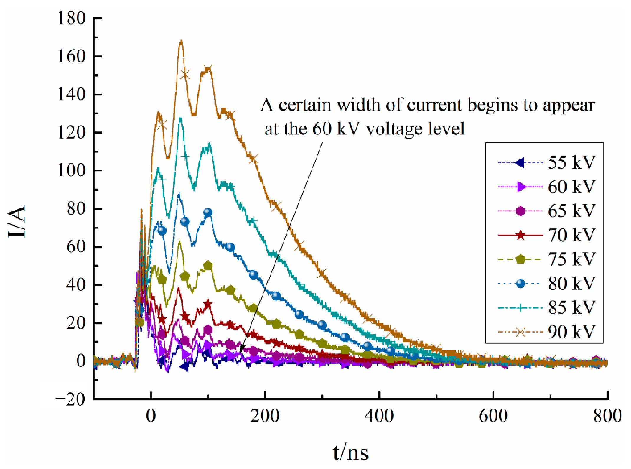
In the high-altitude electromagnetic pulse conduction environment, the action voltage of this type of arrester was about 60 kV, which was 3.53 times its rated working voltage. In other words, a strong electromagnetic pulse with an amplitude below 60 kV could be applied to the power equipment at the back end of the arrester completely without restraint, posing a risk to the insulation of the power equipment.
(b)
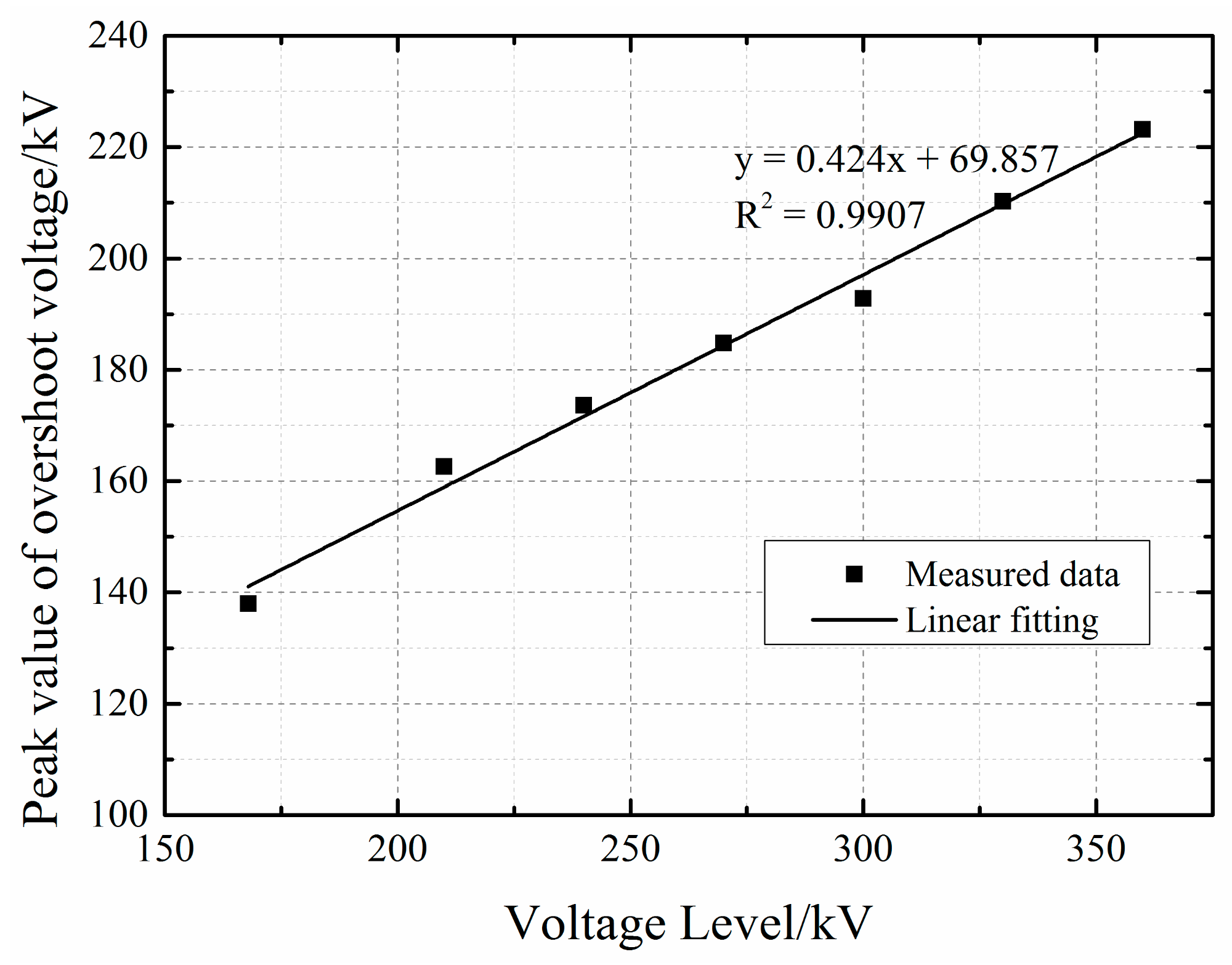
The peak value of overshoot voltage was 2.20 times higher than the residual voltage under the 8/20 μs lightning shock current. Moreover, it was linear with the pulse current, which meant an approx. 10 kV/ns pulse voltage under the 5 kA HEMP conduction current. It poses a greater threat to the insulation of transformers behind the arrester.
(c)
The peak value of residual voltage was 1.57 times higher than the residual voltage under the 8/20 μs lightning shock current. In addition, it was linear with the pulse current amplitude, which meant an above-100 kV residual voltage under the 5 kA HEMP conduction current. Moreover, it took more than ten microseconds for the voltage to decay to zero, which may cause the burning of weak links such as cables and transformer bushings.
(d)
The response time did not vary with the pulse current amplitude, with an average of 46.86 nanoseconds under the HEMP conduction environment. That meant that the response of this type of arrester to high-altitude electromagnetic pulses is not fast enough, such that the rising edge and peak parts will all leak to the back end of the arrester, exerting an adverse impact on the downstream equipment.
Therefore, the existing conventional lightning arresters in the power system are not sufficient to suppress a high-altitude electromagnetic pulse conduction environment. It is necessary to consider developing high-performance arresters with faster response speeds and lower overshoot amplitudes, or adding auxiliary devices such as ferrite magnetic rings to attenuate the pulse steepness at the front end of the lightning arrester.

Author Contributions

F.Q. and W.C. conceived the presented idea; F.Q. and X.W. prepared the specimens; F.Q., Z.C., X.W. and X.N. measured the data; F.Q., T.H., W.C. and Z.C. analyzed the experimental data; and F.Q. primarily wrote the manuscript. All authors have read and agreed to the published version of the manuscript.

Funding

This research was funded by the State Key Laboratory of Intense Pulsed Radiation Simulation and Effect Foundation, grant number SKLIPR1803Z.

Institutional Review Board Statement

Not applicable.

Informed Consent Statement

Not applicable.

Data Availability Statement

Not applicable.

Conflicts of Interest

The authors declare no conflict of interest.

References

  1. Mao, C.; Cheng, Y.; Xie, Y. High Altitude Electromagnetic Pulse Technology Foundation; Science Press: Beijing, China, 2019. (In Chinese) [Google Scholar]
  2. IEC61000-2-10; Electromagnetic Compatibility (EMC)—Part 2-10: Environment—Description of HEMP Environment—Conducted Disturbance; IEC: Geneva, Switzerland, 1998.
  3. Hoad, R.; Radasky, W.A. Progress in High-Altitude Electromagnetic Pulse (HEMP) Standardization. IEEE Trans. Electromagn. Compat. 2013, 55, 532–538. [Google Scholar] [CrossRef]
  4. Xie, H.; Du, T.; Zhang, M.; Li, Y.; Qiao, H.; Yang, J.; Shi, Y.; Wang, J. Theoretical and Experimental Study of Effective Coupling Length for Transmission Lines Illuminated by HEMP. IEEE Trans. Electromagn. Compat. 2015, 57, 1529–1538. [Google Scholar] [CrossRef]
  5. Zhang, H.; Zou, J.; Tian, B.; Tian, M. Flashover Possibility Analysis of Overhead Power Transmission and Distribution Line Insulators with the Excitation of High Altitude Electromagnetic Pulse. Trans. China Electrotech. Soc. 2020, 35, 435–443. (In Chinese) [Google Scholar]
  6. Xie, Y.; Liu, M.; Chen, Y. Electromagnetic Resilience of Critical National Onfrastructure. High Power Laser Part. Beams 2019, 31, 070001–1-8. (In Chinese) [Google Scholar]
  7. Chen, Y.; Xie, Y.; Liu, M.; Gao, C.; Li, M.; Gong, S.; Zhou, J. Analysis of High-Altitude Electromagnetic Effect Models on Power System. High Power Laser Part. Beams 2019, 31, 070007–1-6. (In Chinese) [Google Scholar]
  8. Kozlov, A.; Parfenov, Y.; Chepelev, V.; Shurupov, A.; Shurupov, M.; Chen, Y.; Xie, Y. Assessing Immunity of Power Systems to Effects of High-Voltage Pulses with Power On. High Power Laser Part. Beams 2019, 31, 070006. [Google Scholar]
  9. Xiong, T. Electric Arresters; China Water & Power Press: Beijing, China, 2013. (In Chinese) [Google Scholar]
  10. Martinez, J.A.; Durbak, D.W. Parameter Determination for Modeling Systems Transients—Part V: Surge Arresters. IEEE Trans. Power Deliv. 2005, 20, 2073–2078. [Google Scholar] [CrossRef]
  11. Karbalaye Zadeh, M.; Abniki, H.; Shayegani Akmal, A.A. The Modeling of Metal-Oxide Surge Arrester Applied to Improve Surge Protection. In Proceedings of the 2nd International Conference on Power Electronics and Intelligent Transportation System, Shenzhen, China, 19–20 December 2009; pp. 238–243. [Google Scholar]
  12. Wu, S.; Xiang, X.; Li. H. A Modified Model for Metal-oxide Surge Arrester and Its Parameter Identification. Insul. Surge Arresters 2009, 232, 26–30. (In Chinese) [Google Scholar]
  13. Tai, X.; Li, R.; Xia, J. Influence of Model of Surge Arrester Makes on VFTO Simulation. Northeast. Electr. Power Technol. 2013, 10, 6–11. (In Chinese) [Google Scholar]
  14. He, J.; Tu, Y. Equivalent Calculation Model of Non-linear Resistance of Zinc Oxide. High Volt. Appar. 1998, 6, 50–54. (In Chinese) [Google Scholar]
  15. Zhong, X.; Zhou, L.; Zhao, X.; Deng, H.; Liu, T.; Peng, J. Study on Surge Arrester Model in the Simulation and Calculation of VFTO. Electr. Power Sci. Eng. 2014, 30, 73–77. (In Chinese) [Google Scholar]
  16. Chen, J.; Guo, J.; Wang, L.; Dai, M.; Jiao, L.; Cui, L. The V-A Characteristics under Steep-front Waves of Metal Oxide Surge Arrester Model. Insul. Surge Arresters 2013, 4, 68–74. (In Chinese) [Google Scholar]
  17. Li, Z.; Yan, X.; Wang, H.; He, Z.; Li, X.; Song, J. Analysis of Test and Model for Metal Oxide Arrester under Steep-Front Wave. High Volt. Eng. 2012, 38, 2698–2706. (In Chinese) [Google Scholar]
  18. Valsalal, P.; Udayakumar, K. Importance of Capacitance on Metal Oxide Arrester Block Model for VFTO Applications. IEEE Trans. Power Deliv. 2011, 26, 1294–1295. [Google Scholar] [CrossRef]
  19. Zhang, J.; Jiang, Y.; Zhang, Y.; Li, Y.; Huang, L.; Liu, F. Nanosecond Pulse Response of Typical Voltage-clamping Surge Protective Devices. High Power Laser Part. Beams 2016, 28, 125003. (In Chinese) [Google Scholar]
  20. Zhou, Y.; Xie, Y.; Zhang, D.; Dong, N.; Chen, Y.; Jing, Y. Response of 10-kV Metal-Oxide Surge Arresters Excited by Nanosecond-Level Transient Electromagnetic Disturbances. IEEE Trans. Electromagn. Compat. 2021, 63, 614–621. [Google Scholar] [CrossRef]
  21. Brito, V.S.; Lira, G.R.S.; Costa, E.G.; Maia, M.J.A. A Wide-Range Model for Metal-Oxide Surge Arrester. IEEE Trans. Power Deliv. 2018, 33, 102–109. [Google Scholar] [CrossRef]
  22. Bowman, T.; Halligan, M.; Llanes, R. High-Frequency Metal-Oxide Varistor Modeling Response to Early-time Electromagnetic Pulses. In Proceedings of the IEEE International Symposium on Electromagnetic Compatibility & Signal/Power Integrity (EMCSI), Reno, NV, USA, 28 July–28 August 2020. [Google Scholar]
  23. Cui, Z.; Mao, C.; Sun, B. SPICE Modeling of Pulsed Current Injection with Inductive Coupling. Acta Electron. Sin. 2017, 45, 1513–1517. (In Chinese) [Google Scholar]
  24. GB11032-2010; Metal Oxide Surge Arresters without Gaps for A.C. Systems. AQSIQ; SAC: Beijing, China, 2011. (In Chinese)
Figure 1. The equivalent circuit for the experimental setup.
Energies 15 03303 g001
Figure 2. The short-circuit output current waveform.
Energies 15 03303 g002
Figure 3. Typical waveform of voltage and current of arrester under power-off state: (a) Voltage waveforms; (b) current waveforms.
Energies 15 03303 g003
Figure 4. The volt–ampere characteristic curve of the arrester.
Energies 15 03303 g004
Figure 5. The current passing through arrester.
Energies 15 03303 g005
Figure 6. Peak values of overshoot voltage at different voltage levels.
Energies 15 03303 g006
Figure 7. Peak values of residual voltage at different voltage levels.
Energies 15 03303 g007
Figure 8. Response time at different voltage levels.
Energies 15 03303 g008
Table 1. The basic electrical characteristics of MOV.
TypeRated Voltage/kVResidual Voltage of 8/20 Lightning Shock Current/kVResidual Voltage 30/60 Operation Impact Current/kVDC 1 mA Reference Voltage/kV
Y(H)5WS-17(12.7)/5017(12.7)50.042.525.0
Table 2. The peak values of MOV overshoot voltage.
Voltage Level/kV168210240270300330360
Overshoot Peak Value/kV138.0162.6173.6184.8192.8210.3223.2
Table 3. The peak values of MOV residual voltage.
Voltage Level/kV168210240270300330360
Residual Peak Value/kV85.592.6103.2105.9103.7106.9113.9
Table 4. MOV response time.
Voltage Level/kV168210240270300330360
Average Response Time/ns50.847.948.548.345.344.143.1
Publisher’s Note: MDPI stays neutral with regard to jurisdictional claims in published maps and institutional affiliations.

