
Multi-Cell-to-Multi-Cell Battery Equalization in Series Battery Packs Based on Variable Duty Cycle

Abstract
:1. Introduction
2. Equalization Circuit Analysis
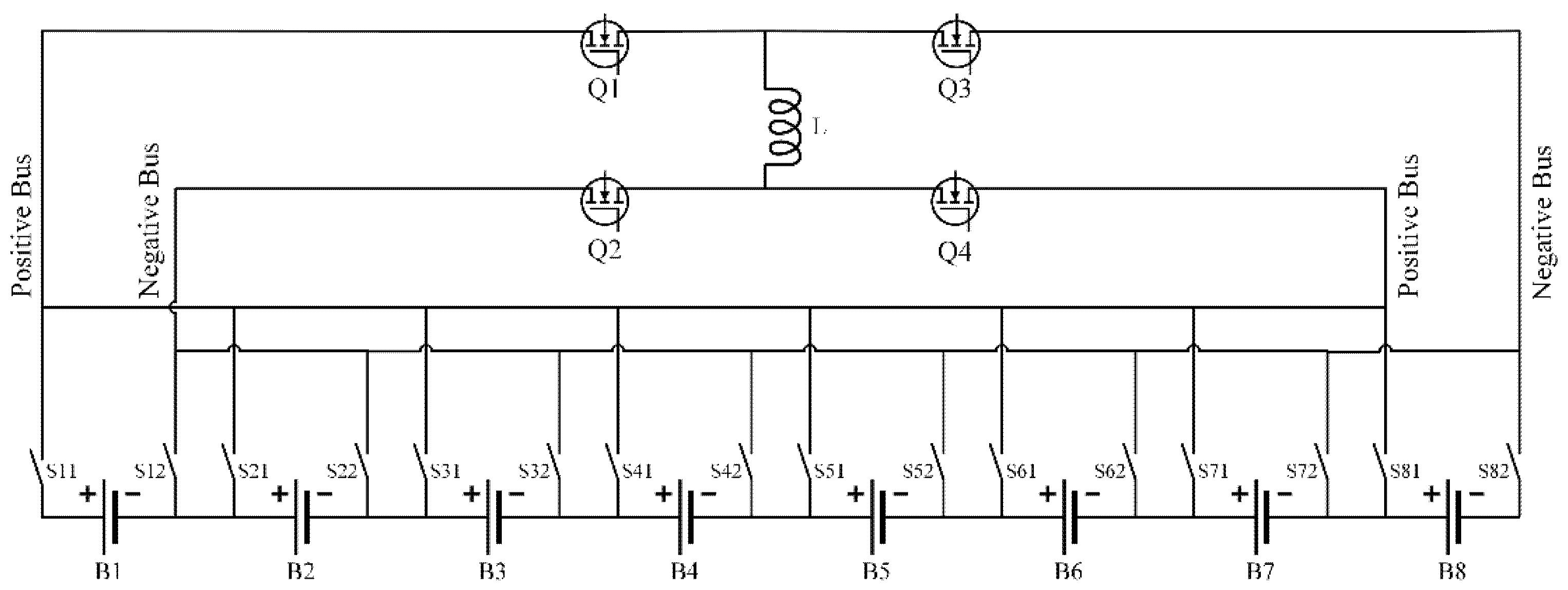
2.1. Balancing Topology
- (1)
- Multiple batteries can be equalized simultaneously in one equalization process, which greatly reduces the equalization time.
- (2)
- Only additional positive and negative switches are needed when the number of series batteries increases. Thus, the circuit complexity remains unchanged; that is, the circuit is easy to expand.
- (3)
- The number of magnetic components, such as inductance and capacitance, is greatly reduced.
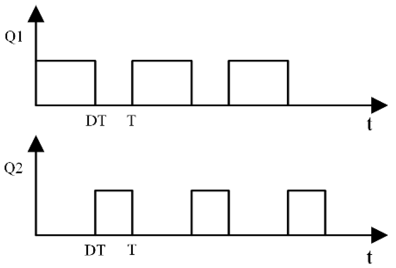
2.2. Principle of Operation
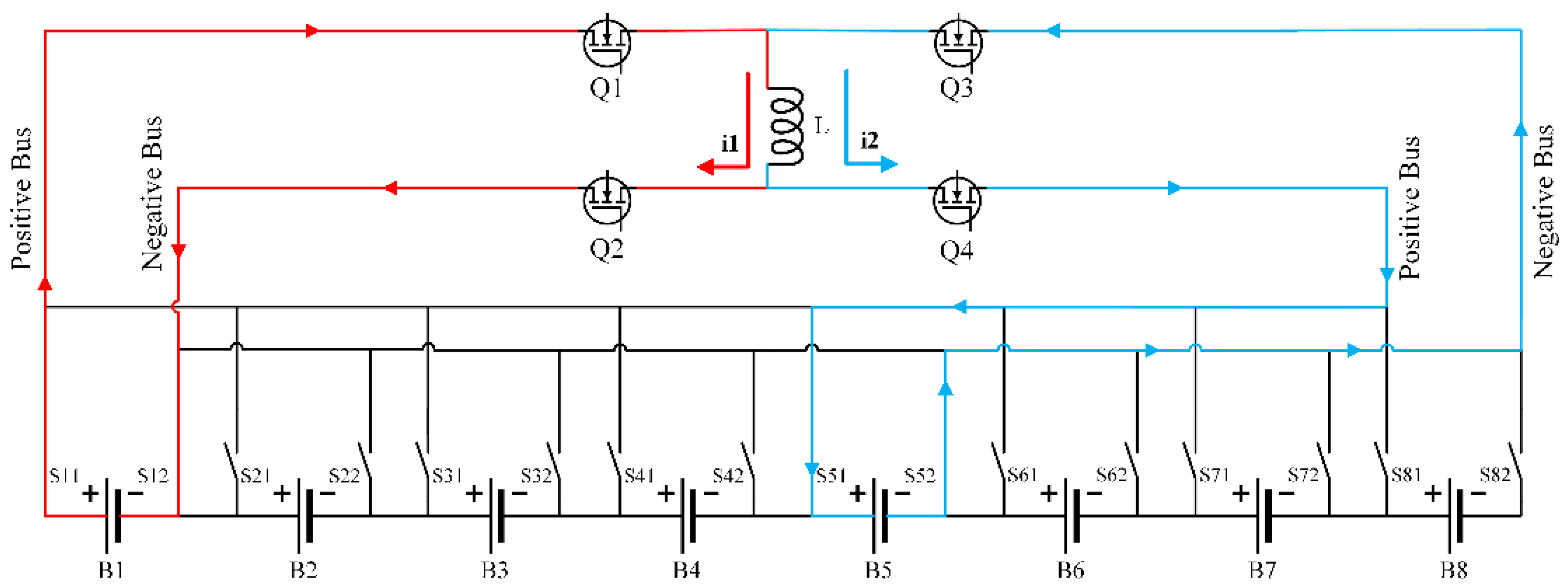
- Source battery B1 discharging: The discharging loop is composed of source battery B1, positive and negative switches S11, S12, MOS transistors Q1, Q2 and inductor L. The current flows along the red arrow. At this time, the electric energy of the source battery B1 is converted into the magnetic energy of the inductor L.
- Target battery B5 charging: The charging loop consists of target battery B5, positive and negative switches S51, S52, MOS transistors Q3, Q4 and inductor L. The current flows along the blue arrow. At this time, the magnetic energy stored in the inductor L is converted into electric energy in the target battery B5.
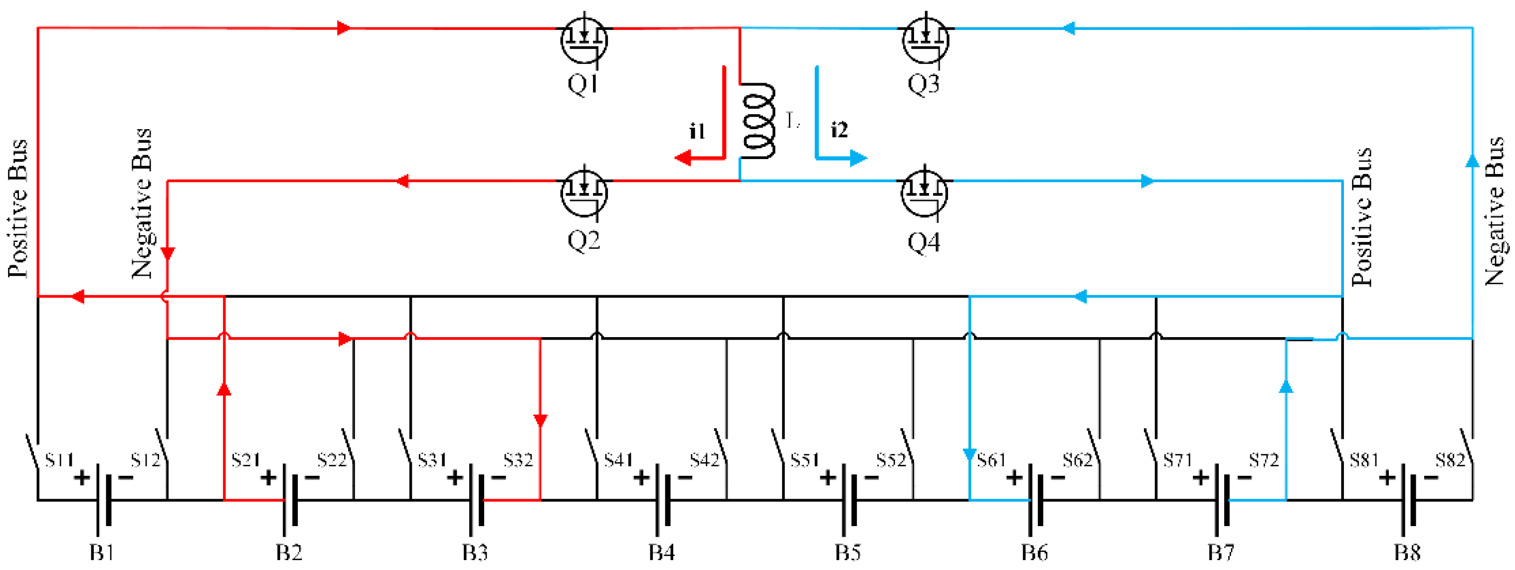
- Battery clusters B2, B3 discharging: The discharging loop is composed of battery clusters B2 and B3, positive and negative switches S21 and S32, MOS transistors Q1, Q2 and inductor L. The current flows along the red arrow. At this time, the electrical energy of the high-energy battery cluster B2 and B3 is converted into the magnetic energy of the inductor L.
- Target battery B5 charging: The charging loop consists of target battery B5, positive and negative switches S51, S52, MOS transistors Q3, Q4 and inductor L. The current flows along the blue arrow. At this time, the magnetic energy stored in the inductor L is converted into electric energy in the target battery B5.
- Battery clusters B2, B3 discharging: The discharging loop is composed of battery clusters B2 and B3, positive and negative switches S21, S32, MOS transistors Q1, Q2 and inductor L. The current flows along the red arrow. At this time, the electrical energy of the high-energy battery cluster B2 and B3 is converted into the magnetic energy of the inductor L.
- Battery clusters B6, B7 charging: The charging loop consists of battery clusters B6 and B7, positive and negative switches S61, S72, MOS transistors Q3, Q4 and inductance L. The current flows along the blue arrow. At this time, the magnetic energy stored in the inductor L is converted into electrical energy in the low-energy battery cluster B6 and B7.
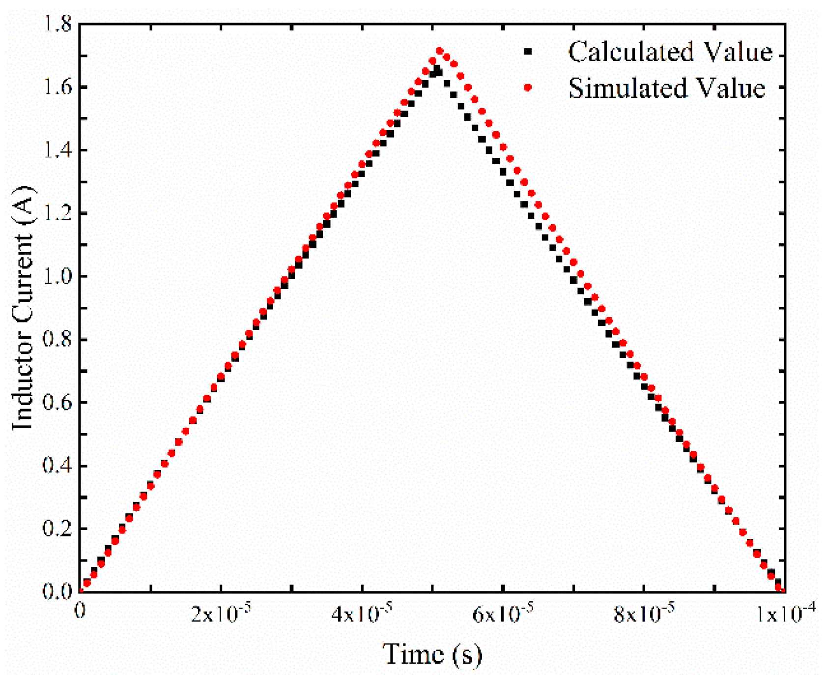
2.3. Simulation Model Verification
3. Analysis of Factors Affecting the Equalization Effect
3.1. Influence of Switching Frequency on Equalization Effect
3.1.1. Influence of Switching Frequency on Duty Cycle
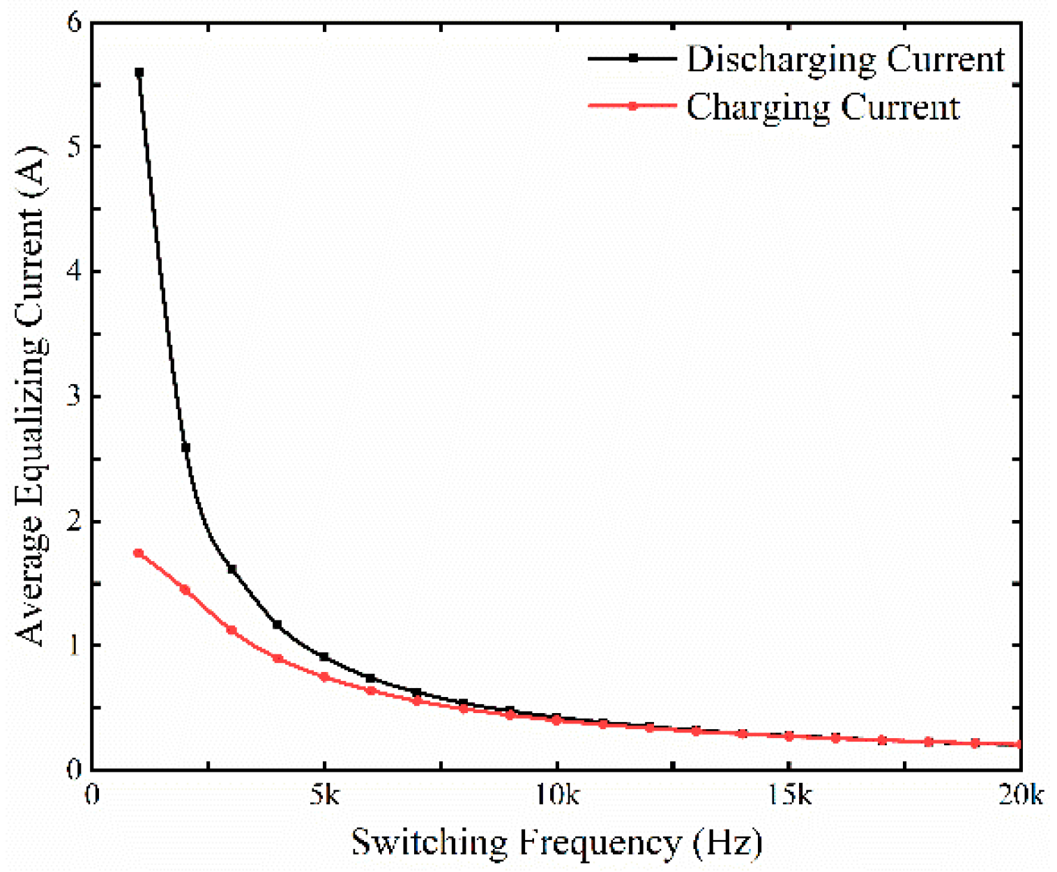
3.1.2. Influence of Switching Frequency on Average Equalizing Current
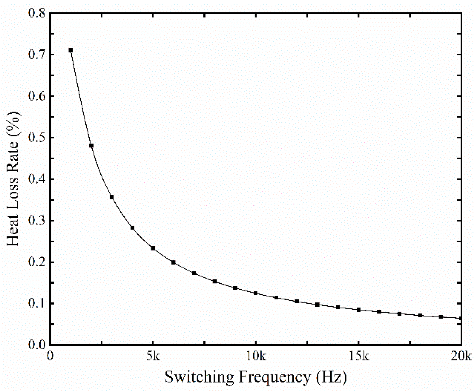
3.1.3. Influence of Switching Frequency on Heat Loss Rate
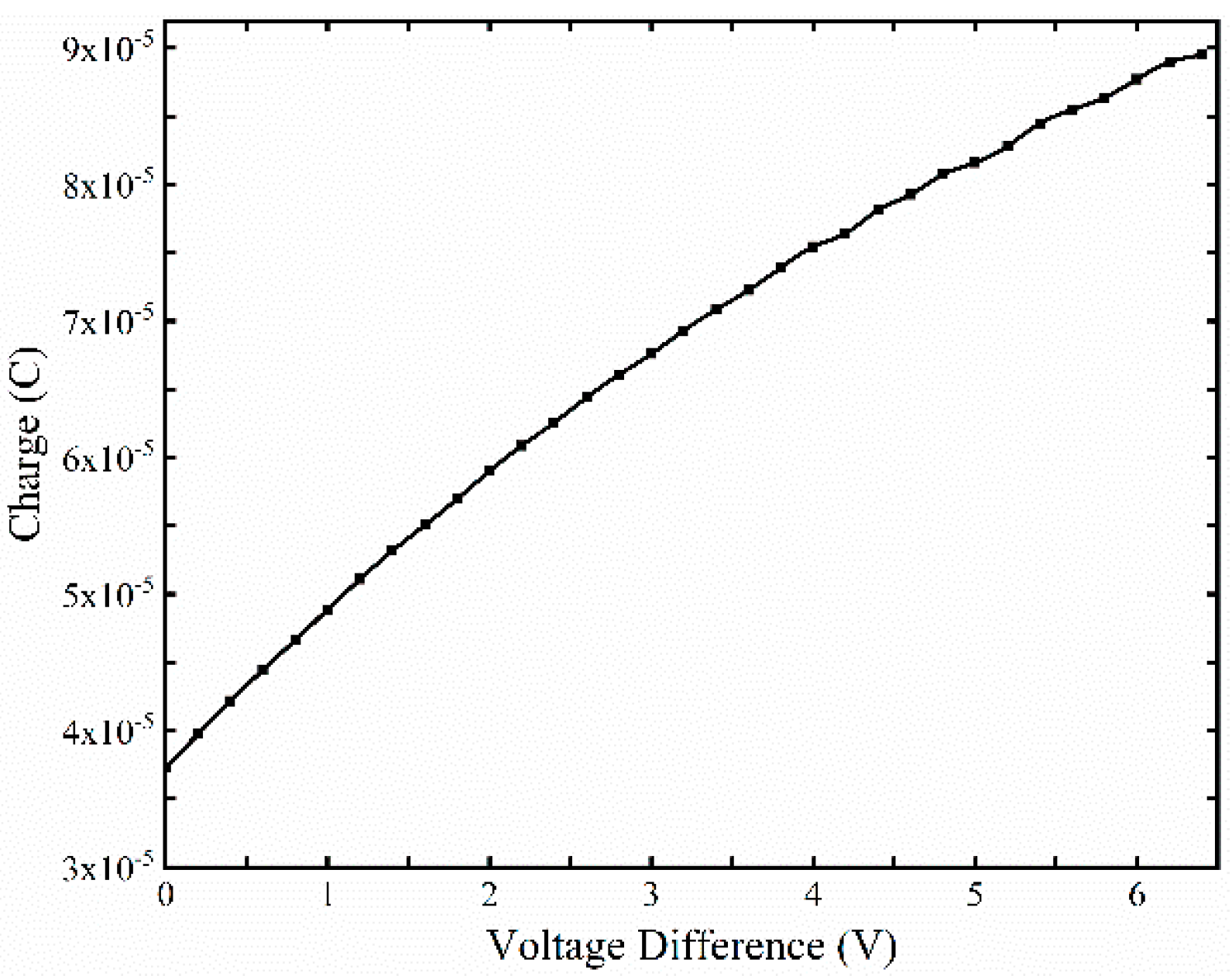
3.2. Influence of Voltage Difference on Equalization Effect
3.2.1. Influence of Voltage Difference on Duty Cycle
3.2.2. Influence of Voltage Difference on Average Balancing Current
- (1)
- The time improvement rate of the two-to-one battery equalization than the one-to-one battery equalization.
- (2)
- The time improvement rate of the three-to-one battery equalization than the two-to-one battery equalization.
- (3)
- The time improvement rate of the three-to-one battery equalization than the one-to-one battery equalization.
3.2.3. Influence of Voltage Difference on Heat Loss Rate
4. Simulation Verification and Analysis
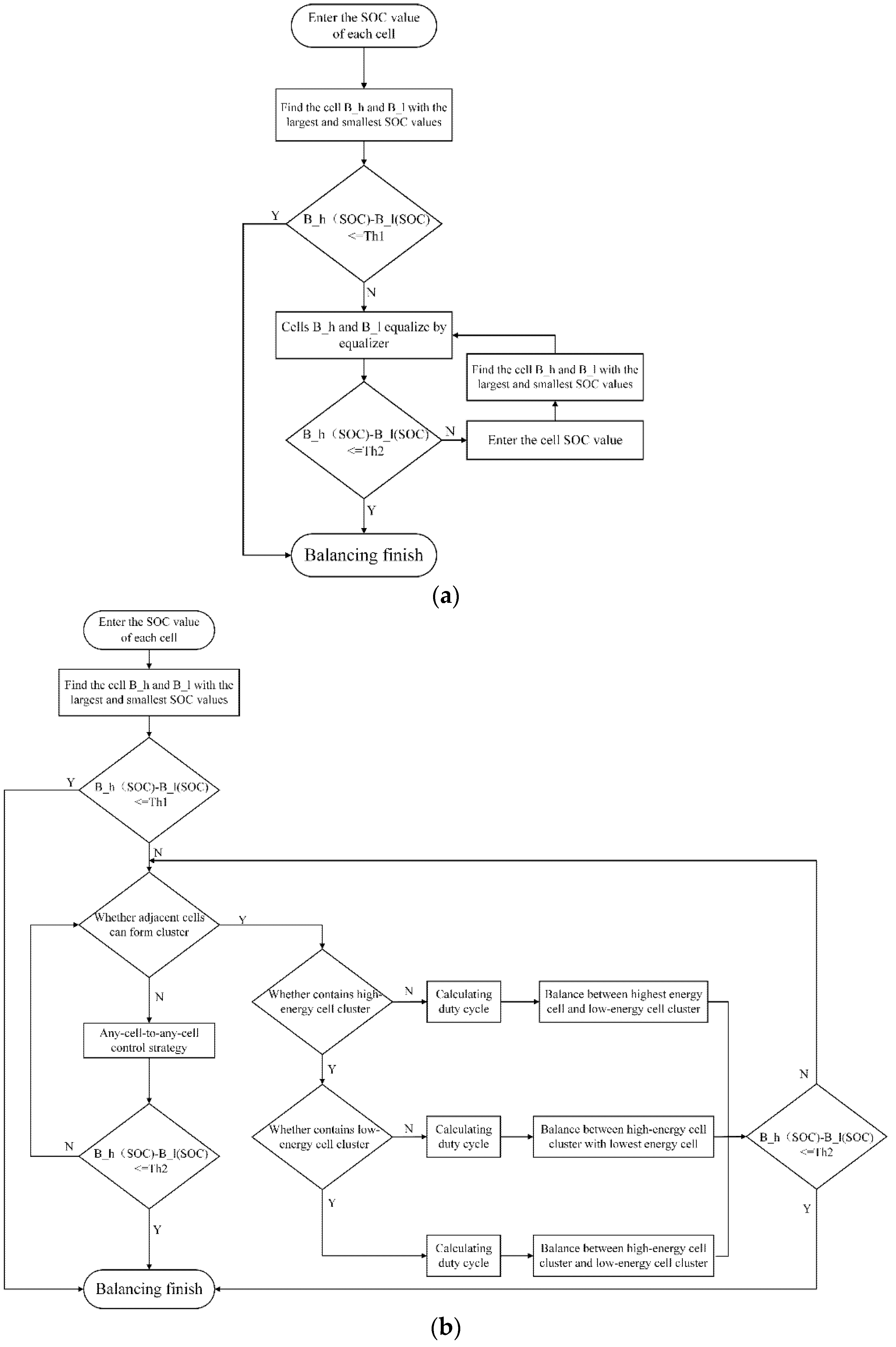
4.1. Balancing Control Strategy
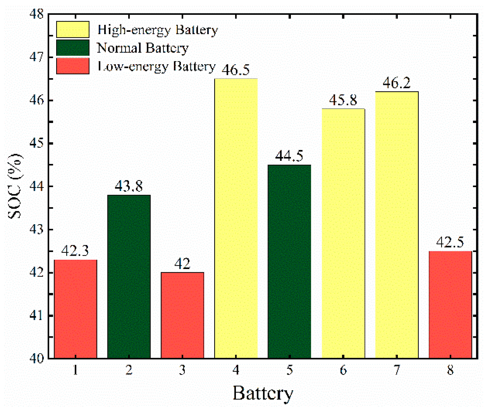
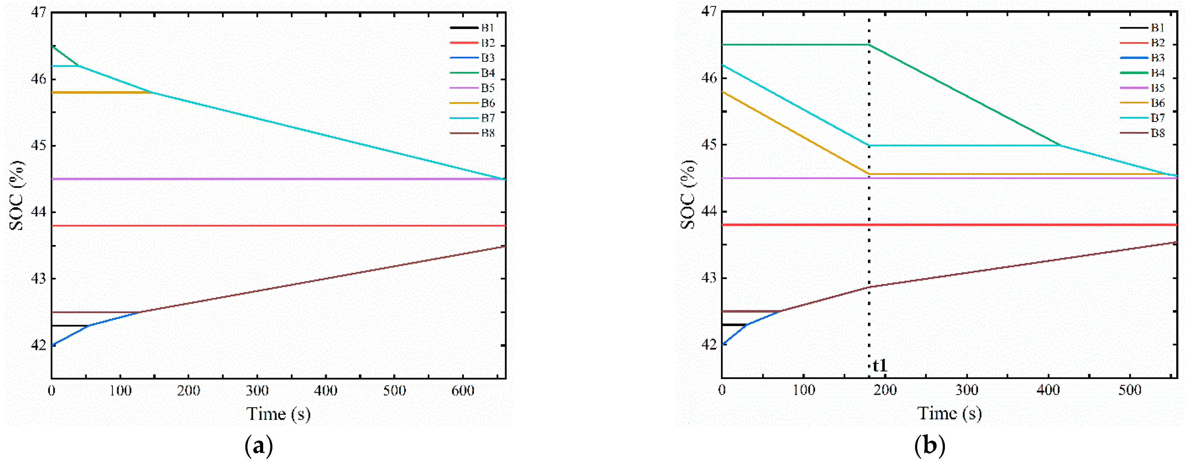
4.2. Multi-Cell-to-Any-Cell Simulation Verification
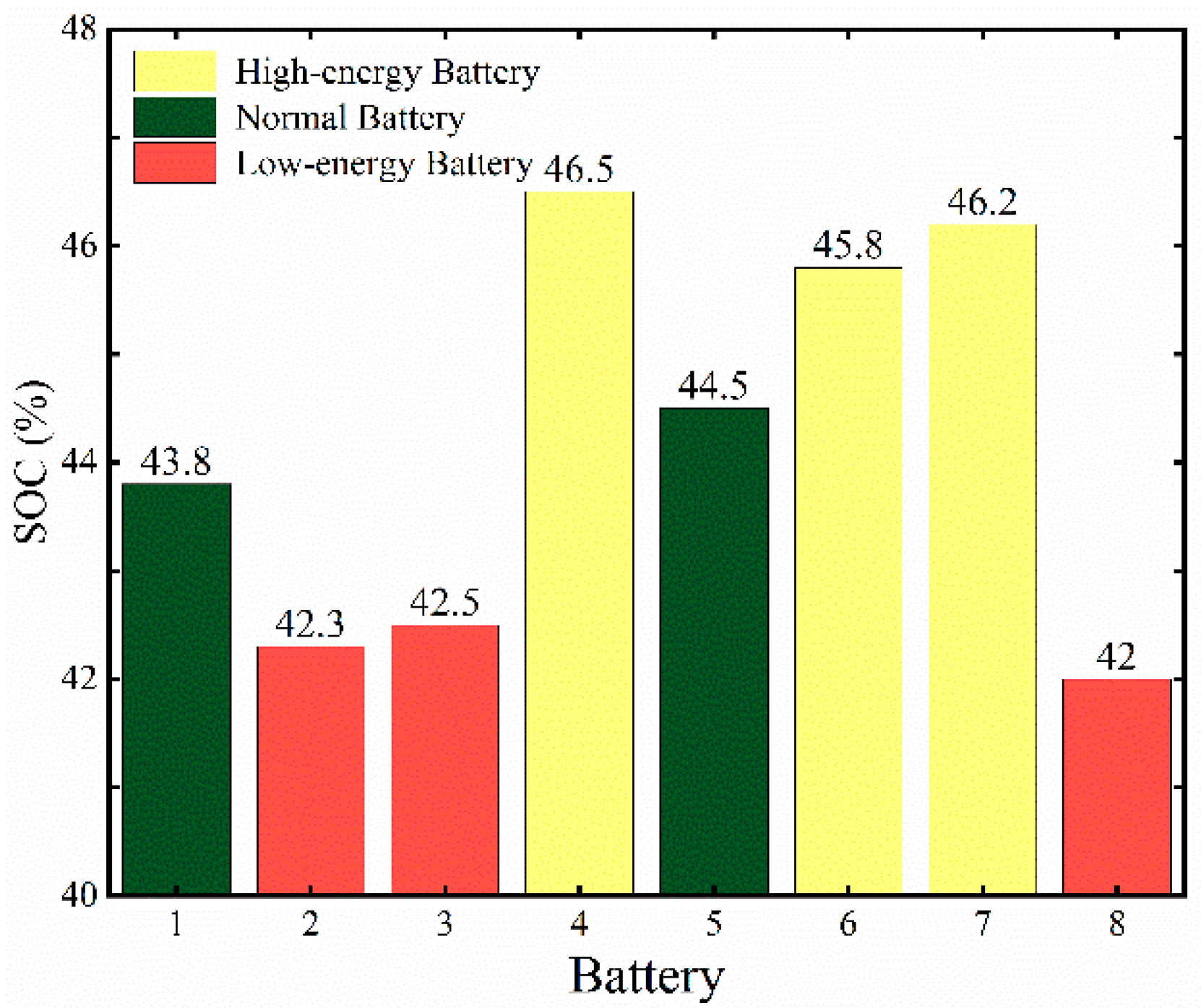
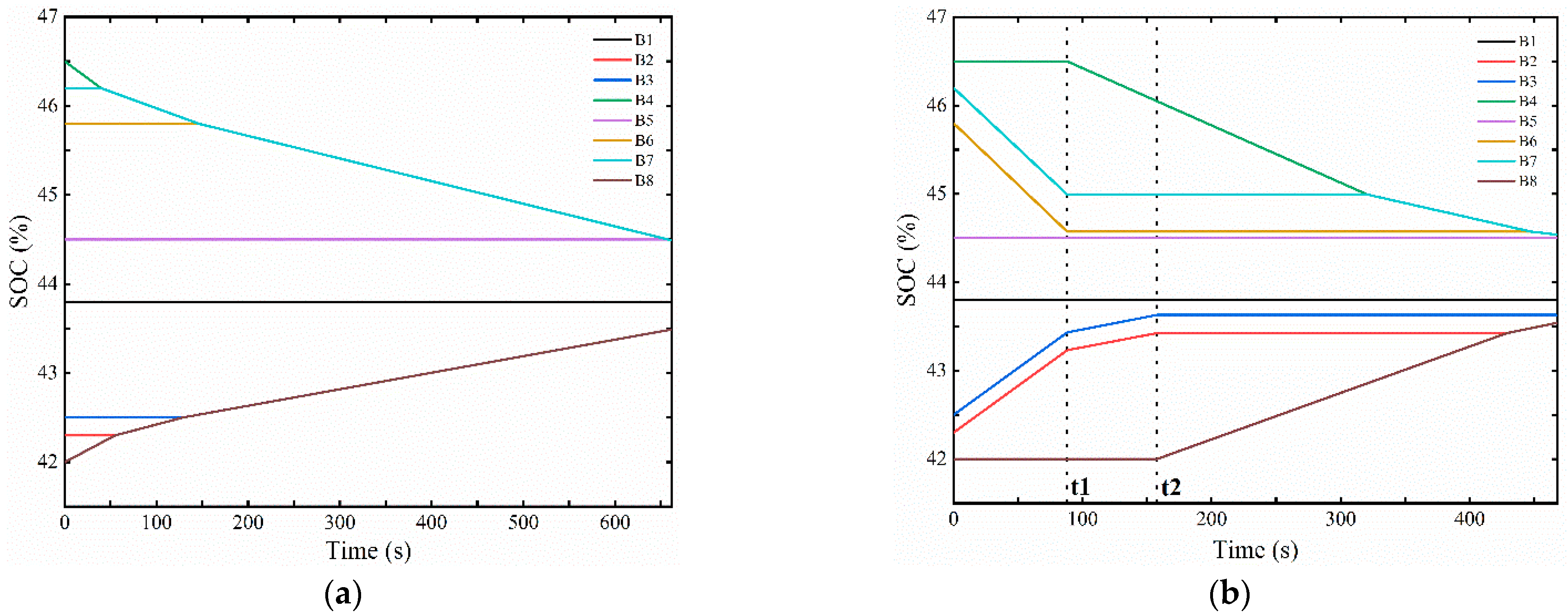
4.3. Multi-Cell-to-Multi-Cell Simulation Verification
5. Conclusions
Author Contributions
Funding
Data Availability Statement
Conflicts of Interest
References
- Zhang, Y. Clean Energy: Opportunities and Challenges. Engineering 2017, 3, 431. [Google Scholar] [CrossRef]
- Gu, D. Dedication to Clean Power and Promotion of the Energy Revolution. Engineering 2020, 6, 1331–1332. [Google Scholar] [CrossRef]
- Davis, L. Clean Energy Perspective. Engineering 2017, 3, 782. [Google Scholar] [CrossRef]
- Li, S.; He, J.; Guo, Z. A Novel Lithium-ion Battery Active Equalization Structure and its Control Strategy Based on Bidirectional Converter Unit. In Proceedings of the 2018 IEEE International Power Electronics and Application Conference and Exposition (PEAC), Shenzhen, China, 4–7 November 2018; pp. 1–5. [Google Scholar]
- Zhang, E.; Xu, C.; Liu, G.; Jiang, K.; Wang, K. An active battery equalization scheme for Lithium iron phosphate batteries. Energy Procedia 2019, 158, 4702–4707. [Google Scholar] [CrossRef]
- Dam, S.; John, V. A Multi-Active-Half-Bridge Converter based Soft-switched Fast Voltage Equalizer for Multi-cell to Multi-cell Charge Transfer. In Proceedings of the 2019 IEEE Transportation Electrification Conference (ITEC-India), Bengaluru, India, 17–19 December 2019; pp. 1–6. [Google Scholar]
- A Hannan, M.; Hoque, M.; Peng, S.E.; Uddin, M.N. Lithium-ion battery charge equalization algorithm for electric vehicle applications. IEEE Trans. Ind. Appl. 2017, 53, 2541–2549. [Google Scholar] [CrossRef]
- Zhang, C.; Shang, Y.; Li, Z.; Cui, N. An Interleaved Equalization Architecture with Self-Learning Fuzzy Logic Control for Series-Connected Battery Strings. IEEE Trans. Veh. Technol. 2017, 66, 10923–10934. [Google Scholar] [CrossRef]
- Ji, L.; Yang, C.; Fathy, H. Nonlinear Model-Predictive Optimal Control of an Active Cell-to-Cell Lithium-Ion Battery Pack Balancing Circuit. IFAC 2017, 50, 14483–14488. [Google Scholar]
- Feng, F.; Hu, X.; Liu, J.; Lin, X.; Liu, B. A review of equalization strategies for series battery packs: Variables, objectives, and algorithms. Renew. Sust. Energ. Rev. 2019, 116, 109464. [Google Scholar] [CrossRef]
- Zhang, S.; Yang, L.; Zhao, X.; Qiang, J. A GA optimization for lithium-ion battery equalization based on SOC estimation by NN and FLC. Int. J. Electr. Power Energy Syst. 2015, 73, 318–328. [Google Scholar] [CrossRef]
- Tudoroiu, R.-E.; Zaheeruddin, M.; Tudoroiu, N.; Radu, S.-M. SOC Estimation of a Rechargeable Li-Ion Battery Used in Fuel-Cell Hybrid Electric Vehicles—Comparative Study of Accuracy and Robustness Performance Based on Statistical Criteria. Part I: Equivalent Models. Batteries 2020, 6, 42. [Google Scholar] [CrossRef]
- Tudoroiu, R.-E.; Zaheeruddin, M.; Tudoroiu, N.; Radu, S.-M. SOC Estimation of a Rechargeable Li-Ion Battery Used in Fuel Cell Hybrid Electric Vehicles—Comparative Study of Accuracy and Robustness Performance Based on Statistical Criteria. Part II: SOC Estimators. Batteries 2020, 6, 41. [Google Scholar] [CrossRef]
- Song, L.; Liang, T.; Lu, L.; Ouyang, M. Lithium-ion battery pack equalization based on charging voltage curves. Int. J. Electr. Power Energy Syst. 2020, 115, 105516. [Google Scholar] [CrossRef]
- Li, K.; Zong, X.; Liu, Q.; Sun, Y.; Xue, F. Design of an Active Battery Equalization Circuit with DC-DC Converter. In Proceedings of the 2021 3rd Asia Energy and Electrical Engineering Symposium (AEEES), Chengdu, China, 26–29 March 2021; pp. 863–866. [Google Scholar]
- Zhang, H.; Wang, Y.; Qi, H.; Zhang, J. Active Battery Equalization Method Based on Redundant Battery for Electric Vehicles. IEEE Trans. Veh. Technol. 2019, 68, 7531–7543. [Google Scholar] [CrossRef]
- Park, S.; Park, K.; Kim, H.; Moon, G.; Youn, M. Single-Magnetic Cell-to-Cell Charge Equalization Converter with Reduced Number of Transformer Windings. IEEE Trans. Power Electron. 2011, 27, 2900–2911. [Google Scholar] [CrossRef]
- Ma, Y.; Duan, P.; Sun, Y.; Chen, H. Equalization of Lithium-Ion Battery Pack Based on Fuzzy Logic Control in Electric Vehicle. IEEE Trans. Ind. Electron. 2018, 65, 6762–6771. [Google Scholar] [CrossRef]
- Li, Y.; Xu, J.; Mei, X.; Wang, J. A Unitized Multiwinding Transformer-Based Equalization Method for Series-Connected Battery Strings. IEEE Trans. Power Electron. 2019, 34, 11981–11989. [Google Scholar] [CrossRef]
- Pascual, C.; Krein, P.T. Switched capacitor system for automatic series battery equalization. In Proceedings of the APEC 97—Applied Power Electronics Conference, Atlanta, GA, USA, 27 February 1997; Volume 2, pp. 848–854. [Google Scholar]
- Lee, Y.; Cheng, M. Intelligent control battery equalization for series connected lithium-ion battery strings. IEEE Trans. Ind. Electron. 2005, 52, 1297–1307. [Google Scholar] [CrossRef]
- Daowd, M.; Antoine, M.; Omar, N.; Van den Bossche, P.; Van Mierlo, J. Single Switched Capacitor Battery Balancing System Enhancements. Energies 2013, 6, 2149–2174. [Google Scholar] [CrossRef] [Green Version]
- Li, S.; Mi, C.; Zhang, M. A High-Efficiency Active Battery-Balancing Circuit Using Multiwinding Transformer. IEEE Trans. Ind. Appl. 2012, 49, 198–207. [Google Scholar] [CrossRef]
- Kutkut, N.; Wiegman, H.; Divan, D.; Novotny, D. Design considerations for charge equalization of an electric vehicle battery system. IEEE Trans. Ind. Appl. 1999, 35, 28–35. [Google Scholar] [CrossRef] [Green Version]
- Liu, Y.; Xia, C.; Gu, M.; Xin, W.; Men, X. A novel active equalizer for Li-ion battery pack in electric vehicles. Energy Procedia 2019, 158, 2649–2654. [Google Scholar] [CrossRef]
- Shang, Y.; Xia, B.; Zhang, C.; Cui, N.; Yang, J.; Mi, C. An Automatic Equalizer Based on Forward-Flyback Converter for Series-Connected Battery Strings. IEEE Trans. Ind. Electron. 2017, 64, 5380–5391. [Google Scholar] [CrossRef]
- Shang, Y.; Cui, N.; Zhang, C. An Optimized Any-Cell-to-Any-Cell Equalizer Based on Coupled Half-Bridge Converters for Series-Connected Battery Strings. IEEE Trans. Power Electron. 2018, 34, 8831–8841. [Google Scholar] [CrossRef]
- Daowd, M.; Omar, N.; Van den Bossche, P.; Van Mierlo, J. A Review of Passive and Active Battery Balancing Based on MATLAB/Simulink. Int. Rev. Electr. Eng.-IREE. 2011, 6, 2974–2989. [Google Scholar]
- Das, U. Advancement of lithium-ion battery cells voltage equalization techniques: A review. Renew. Sust. Energ. Rev. 2020, 134, 110227. [Google Scholar] [CrossRef]
- Wang, B.; Qin, F.; Zhao, X.; Ni, X.; Xuan, D. Equalization of series connected lithium-ion batteries based on back propagation neural network and fuzzy logic control. Int. J. Energy Res. 2020, 44, 4812–4826. [Google Scholar] [CrossRef]
- Wu, X.; Cui, Z.; Li, X.; Du, J.; Liu, Y. Control Strategy for Active Hierarchical Equalization Circuits of Series Battery Packs. Energies 2019, 12, 2071. [Google Scholar] [CrossRef] [Green Version]
- Wang, S.; Yang, S.; Yang, W.; Wang, Y. A New Kind of Balancing Circuit With Multiple Equalization Modes for Serially Connected Battery Pack. IEEE Trans. Ind. Electron. 2020, 68, 2142–2150. [Google Scholar] [CrossRef]
- Chen, Y. An any-cell(s)-to-cell(s) equalization method with a single magnetic component for Lithium-ion battery pack. J. Energy Storage 2020, 33, 102071. [Google Scholar] [CrossRef]
- Wu, T.; Qi, Y.; Liao, L.; Ji, F.; Chen, H. Research on equalization strategy of lithium-ion batteries based on fuzzy logic control. J. Energy Storage 2021, 40, 102722. [Google Scholar] [CrossRef]
- Shang, Y.; Zhang, Q.; Cul, N.; Duan, B.; Zhou, Z.; Zhang, C. Multicell-to-Multicell Equalizers Based on Matrix and Half-Bridge LC Converters for Series-Connected Battery Strings. IEEE J. Emerg. Sel. Top. Power Electron. 2019, 8, 1755–1766. [Google Scholar] [CrossRef]


| Switching Frequency | 1 k | 2 k | 3 k | 4 k | 5 k | 6 k | 7 k | 8 k | 9 k | 10 k |
| Duty Cycle | 0.702 | 0.603 | 0.564 | 0.543 | 0.531 | 0.523 | 0.517 | 0.512 | 0.509 | 0.506 |
| Switching Frequency | 11 k | 12 k | 13 k | 14 k | 15 k | 16 k | 17 k | 18 k | 19 k | 20 k |
| Duty Cycle | 0.504 | 0.502 | 0.5 | 0.499 | 0.498 | 0.497 | 0.496 | 0.495 | 0.494 | 0.494 |
| Voltage Difference | 0 | 0.8 | 1.6 | 2.4 | 3.2 | 4 | 4.8 | 5.6 | 6.4 |
| Duty Cycle | 0.525 | 0.469 | 0.424 | 0.387 | 0.356 | 0.33 | 0.307 | 0.287 | 0.269 |
| Equalization Strategy | After Equalization | |||||
|---|---|---|---|---|---|---|
| The SOC of Each Cell | Average | Range | Variance | Time (s) | ||
| AC2AC Equalization | 43.49 | 44.49 | 44.0275 | 1 | 0.2223 | 662 |
| 43.79 | 44.49 | |||||
| 43.49 | 44.49 | |||||
| 44.49 | 43.49 | |||||
| MC2AC Equalization | 43.54 | 44.49 | 44.06625 | 1 | 0.2193 | 557.126 |
| 43.8 | 44.54 | |||||
| 43.54 | 44.54 | |||||
| 44.54 | 43.54 | |||||
| Equalization Strategy | After Equalization | |||||
|---|---|---|---|---|---|---|
| The SOC of Each Cell | Average | Range | Variance | Time (s) | ||
| AC2AC Equalization | 43.8 | 44.49 | 44.02875 | 1 | 0.2218 | 662 |
| 43.49 | 44.49 | |||||
| 43.49 | 44.49 | |||||
| 44.49 | 43.49 | |||||
| MC2MC Equalization | 43.8 | 44.49 | 44.0775 | 1 | 0.2084 | 467.379 |
| 43.54 | 44.54 | |||||
| 43.63 | 44.54 | |||||
| 44.54 | 43.54 | |||||
Publisher’s Note: MDPI stays neutral with regard to jurisdictional claims in published maps and institutional affiliations. |
© 2022 by the authors. Licensee MDPI, Basel, Switzerland. This article is an open access article distributed under the terms and conditions of the Creative Commons Attribution (CC BY) license (https://creativecommons.org/licenses/by/4.0/).
Share and Cite
Luo, S.; Qin, D.; Wu, H.; Wang, T.; Chen, J. Multi-Cell-to-Multi-Cell Battery Equalization in Series Battery Packs Based on Variable Duty Cycle. Energies 2022, 15, 3263. https://doi.org/10.3390/en15093263
Luo S, Qin D, Wu H, Wang T, Chen J. Multi-Cell-to-Multi-Cell Battery Equalization in Series Battery Packs Based on Variable Duty Cycle. Energies. 2022; 15(9):3263. https://doi.org/10.3390/en15093263
Chicago/Turabian StyleLuo, Shengyi, Dongchen Qin, Hongxia Wu, Tingting Wang, and Jiangyi Chen. 2022. "Multi-Cell-to-Multi-Cell Battery Equalization in Series Battery Packs Based on Variable Duty Cycle" Energies 15, no. 9: 3263. https://doi.org/10.3390/en15093263
APA StyleLuo, S., Qin, D., Wu, H., Wang, T., & Chen, J. (2022). Multi-Cell-to-Multi-Cell Battery Equalization in Series Battery Packs Based on Variable Duty Cycle. Energies, 15(9), 3263. https://doi.org/10.3390/en15093263