Article

An Integrated Elitist Approach to the Design of Axial Flux Permanent Magnet Synchronous Wind Generators (AFPMWG)

1
School of Construction Management and Engineering, University of Reading, Reading RG6 6AH, UK
2
Department of Electrical Engineering, IAU-Birjand Branch, Birjand 9717811111, Iran
*
Author to whom correspondence should be addressed.
Energies 2022, 15(9), 3262; https://doi.org/10.3390/en15093262
Submission received: 28 January 2022 / Revised: 11 April 2022 / Accepted: 25 April 2022 / Published: 29 April 2022

Abstract

:
This paper addresses an integrated and developed approach to the design of an Axial Flux Permanent Magnet Wind Generator (AFPMWG). The proposed analytical method of design employs the size equations and precise inductance calculations simultaneously, as well as considering the mechanical constraints of the back-iron disc of the rotor. An Elitist Genetic Algorithm (EGA), such as a high capability optimization method, has been used to solve the equations and design of a wind generator with predefined rating power. The objectives of the coreless AFPMWG design process are minimizing the magnet consumption, maximizing machine efficiency, and achieving maximum sinusoidal induction voltage, considering the wind properties of the geographical area of utilization. The optimal calculation of the permanent magnet thickness is also taken into consideration in this work. The flux density distribution in all parts of the machine has been investigated for the magnetic saturation phenomenon. In this regard, special attention is paid to rotor back discs, which are made from nonlinear material with an optimum thickness. The inductance of the leakage flux of the coreless machine has been considered by parallel computation via the Finite Element Method (FEM) and analytical equations. Finally, three-dimensional and two-dimensional finite element analyses are used to validate the performance of the machine design according to the characteristics of Iran wind resources. The results show the high ability of the proposed approach in AFPMWG design and in considering the objectives and constraints carefully.

1. Introduction

By the end 2018, global renewable power generation reached 2351 GW, of which 24% (564 GW) was attributed to wind power [1]. Although a global target for wind power to be 50% of all renewable power has been set for 2030 [2], current projections suggest the proportion is more likely to be between 20% and 25% (1300 GW) [3,4]. Therefore, significant changes are required in wind energy policies and the related technologies and apparatus in order to meet the intended target.
Wind turbines are generally divided into two types of those with and without gearboxes. The main disadvantages of gearbox are high maintenance costs, high weight, and noise generation [5]. Additionally, in the gearbox-based turbines, system losses are high and thereupon the efficiency is low compared to the gearbox-less type. In wind energy systems, using a low-speed generator is a way to remove the gearbox and so the rotor speed would be equal to the rotational speed of the turbine. A detailed comparison between these types of wind energy conversion systems has been provided in reference [5]. This analysis has led to the conclusion that the direct-drive permanent-magnet generator could be the best solution. Due to the elimination of the brushes and gearbox, it has the advantages of a fully rated converter.
The minimum required speed in gearless turbines is a serious constraint and is often subjected to designing a specific type of generator for this application. Permanent magnet generators provide the required frequency at low speeds by increasing the number of poles. The magnetic fluxes generated by these poles can be in the radial or axial direction of the machine. So, the types of permanent magnet generators are then categorized as axial flux and radial flux [6].
Due to the axial movement of the air gap flux, these are of the disc-shaped machines [7]. This structure, because of the higher ratio of the diameter of the machine to its length, exhibits characteristics such as high torque density and high efficiency, as well as is suitable for design with a high number of poles. These advantages make the axial flux permanent magnet synchronous generator the best option for coupling with gearless wind turbines [8].
Permanent-magnet machines are diverse in terms of rotor and stator construction. These machines can be in the form of a single- or double-side rotor, slot-less and coreless stator, or with a slotted stator and core. Furthermore, the permanent magnet can be buried in or attached to the surface of the rotor disk [9].
Double-sided permanent-magnet machines are often preferable due to the balance of the force between of the discs. This topology consists of a stator placed between two rotor discs [10]. The main advantages of coreless stator machines are the lack of cogging torque, low weight, high efficiency, and simple structure. However, concern has been reported about the harmonics from a grid perspective. The absorbent force between the rotor and stator discs, which has contributed to the structural strength of the machine, can also be neglected with a coreless stator [11].
A comparison of the ferrite magnet performance in the axial flux machine and radial flux-type reported in references [12,13] provides a comprehensive overview of the application of different magnets in these machines. The results show that the low-cost ferrite magnet has much lower energy than the NdFeB magnet and is not advisable.
In reference [14], the spoke-type permanent-magnet Vernier machine has been used for direct-drive applications. This type of design reduces the ratio of pole width to pole pitch, which results in the decline of the machine power. So, increasing the number of machine poles is mandatory. Due to the arrangement type of the poles, only the structure of a single rotor and dual stators on both sides of the rotor can be used for this application. Therefore, the copper losses in these types of machines are much higher than their rivals.
The development and improvement of the design approach as well as the optimization of the related equations are paramount to achieving the best topology. In this regard, it is proposed in reference [15] to develop and improve the design of an axial flux permanent magnet synchronous generator using a genetic algorithm. The objective of this study is to minimize the production cost and its indicator is the total price of the magnet. Based on the finding of this research, the utilization of a core in the stator has resulted in the generation of cogging torque in this machine. To reduce the effect of cogging torque, a permanent-magnet-shift mechanical technique has been used in [16]. Cogging torque is an inherent feature of permanent-magnet machines, which results in rising inertia and an inappropriate start-up speed. The acceptable value for cogging torque is 1–2% of total generator torque. In this study, the weight of magnetic materials has increased dramatically, which is not economic.
In reference [11], the optimal ratio between the number coils and poles, minimizing the effective weight of the permanent magnet and maximizing the annual energy production of the slot-less axial flux generator has been investigated. Due to the lack of an integrated method in this study, some important quantities such as coil weight have been non-optimally obtained. The optimization of a slotted motor which is driven by a spiral-type stator using a Genetic Algorithm and the related comprehensive dimensional equations are presented in reference [17]. The principal aims of this research are maximizing the sinusoidal voltage and power density, as well as reducing cogging torque. The analysis of a permanent magnet flux machine with a coreless stator is presented by reference [18]. The article makes a comparison between the performance of two types of non-overlapping concentrated stator windings.
In the analysis and the design of AFPM machines, a set of parameters including the air gap flux density, cogging torque, effective weight of consumables, eddy current losses, efficiency, and magnetic-field leakage flux have been conventionally considered by the researchers [19]. In the design of electric machines, there are other optional variables that the designer determines according to the objectives of the design or based on the experience. These variables affect the performance characteristics and the dimensions of the machine. The GA featuring a population of parallel points to be searched as opposed to a single-point search of the nonlinear nature of optimization makes GA the most suited technique for this application [20].
The magnetic field of an electric machine can be determined analytically or numerically via the Finite-Element Method (FEM). FEM is more accurate than the analytical method and can be used in the machines with complex structures and a special magnetic circuit rather than the conventional Radial Flux Permanent Magnet (RFPM) Machines [21,22].
In the design of the AFPM machines, with due attention to the high cost of permanent magnet materials, limitations in the dimensions and size of the machine, the necessity of power generation at low speeds, coherence and the strength of the machine structure, a reduction of the machine losses including cogging torque, copper and hysteresis losses, high efficiency, and high-power density, it is absolutely essential to have an integrated design approach. This important process can be achieved using the elitist genetic algorithm optimization technique, as well as being validated by the finite element simulation.
The review of the literature, considering the advantages and disadvantages of various types of AFPM machines from a technical perspective and consistent with the wind speed of the geographical area of operation, has led to finding the best topology for this application. In the course of this research, two rotors joined with a single-core slot-less stator structure was selected as the best suit. When this structure uses in an optimal design, it is capable of reducing copper loss, increasing power density, mitigating cogging torque, and reducing the total weight.
The earlier evaluations have illustrated that the Genetic Algorithm is the most powerful metaheuristic optimization approach when finding the global optima is the main concern and there is no restricted time limitation [23]. Therefore, genetic optimization algorithms have been used to design this machine when maximizing the efficiency and induction voltage, as well as when minimizing the weight of the permanent magnet. Afterward, finite element analysis has been used to evaluate the robustness of the proposed approach.

2. Wind Speed and Wind Turbine Characteristics

The design of an AFPM generator for coupling it to a wind turbine requires careful study of wind and turbine speed characteristics. Turbine performance within a wide range of different wind speeds is not only important for obtaining maximum power, but also affects the feasibility studies of wind power generation (sitting and sizing). The characteristics of the wind turbine and wind speed are discussed in the following two sub-chapters.

2.1. Wind Turbine Specifications

In this research, a new integrated approach is proposed in order to design a wind generator. Therefore, it is essential to pay attention to the characteristics of wind turbines. The output power from the propeller shaft of a wind turbine is equivalent to the input power to the generator in a gearless system. This output shaft power for a direct drive turbine-generator is described as follows [11,24]:
P s h a f t = P i n = 0.5   ρ a i r C p λ   ,   β π R b 2   V w 3
where, Pshaft (kW) is the mechanical output power of the turbine or the output power of the shaft, Cp(λ, β) is the turbine power factor, ρair is the air density in Kg/m2, R b is the turbine blade radius (m), Vw is the wind speed (m/s), λ is the turbine Tip Speed Ratio (TSR) and β is the angle of the turbine pitch. The necessary relation for expressing the turbine power factor parameter (Cp) in terms of turbine characteristics is given in Equations (2) and (3) [25]:
    C p λ   ,   β = C 1 C 2 λ i C 3 β C 4 e c 5 λ + C 6 λ
1 λ i = 1 λ + 0.08 β 0.035 β 3 + 1
Considering the references [24,25], the values of the coefficients C1 to C6 are set equal to C1 = 0.5176, C2 = 116, C3 = 0.4, C4 = 5, C5 = 21, and C6 = 0.0068, and reach a maximum Cp of 0.48 at β = 0 and λ = 6.7. It can be stated that the power conversion efficiency in the current system is dependent on the tip speed. This value is given in Equation (4):
λ = ω m R b V m
where ωm is the angular velocity (radian/s). Combining Equations (2) and (4) for the power factor (Cp), which is a function of λ and β, yields the result of Equation (5):
C p λ   ,   β = 0.51 116 λ i 0.4 β 5 e 21 λ 0.0068 λ

2.2. Characteristics of Wind Speed

The careful analysis of generator performance at various wind speeds is dependent on the study of wind characteristics in the proposed region. In other words, the amount of energy generated by the wind turbine follows from the distribution of wind speed in the installed area. The Rayleigh distribution curve is used in most wind data analyses [11,24,25]. Figure 1 shows the Rayleigh distribution curve for a wide range of wind speeds.
The wind turbine specifications are presented in Table 1. These specifications are computed using Equations (1)–(5) for the weather conditions of a 1400 to 1500 m height above sea level. Obviously, changing some of the features such as height and wind speed can lead to a different design of the blade length and variation in the rotational speed. Therefore, selecting a wind turbine installation location is dependent on providing the minimum required rotational speed for the dominant weather conditions of Iran, which is equal to 250 rpm [26].

3. Main Design Equations

The main parameters of an ironless Axial Flux Permanent Synchronous Generator (AFPMSG), such as diameter, can be expressed using the output power equation by ignoring the leakage flux of the machine [9,27]. The output power is given by the Equation (6):
P o u t = m k p η E p k I p k
where η is the efficiency of the machine, Epk and Ipk are the maximum voltage and the peak of the phase current of the Electric Movement Force (EMF), respectively. m is the number of machine phases, and Kp is the power waveform coefficient which is visually presented in Table 2 and can be found by the following equation:
K p = 1 T 0 T e t i t E P k I P k d t
where T is the period of one cycle (EMF), e(t) is the induction voltage caused by the flux density of the air gap, and i(t) is phase current. Assuming the sinusoidal density of the air gap flux, the maximum induced phase voltage of the AFPM machine is shown in Equation (8):
E p k = 2 4 B g n s N p h D o u t 2 1 k d 2
where N p h is the number of winding turns per phase, B g is the air gap flux density, Dout is the outer diameter of the machine, ns is the synchronous speed, and k d is the ratio of the inner diameter to the outer diameter of the machine.
Related to Equation (6), the maximum phase current is given by Equation (9):
I p k = A π 1 + k d 4 2 m N p h
where m is the number of phases and A is the specific electric loading of the machine.
The specific electric loading of a machine is the circumferential current density of the stator. The range of specific electric loading values (A) for small PM machines is typically 10,000–40,000 A/m [28,29]. In the general case, the total electrical loading A should include both the stator electrical loading As and rotor electrical loading Ar, so that:
A s   = A A r   = A 1 + K ϕ
where Kϕ = Ar/As is the ratio of electrical loading on the rotor and stator. In a machine topology without a rotor winding Kϕ = 0 [27].
Therefore, combining Equations (6) and (9) yields the main and final equation of the output power of an AFPM machine, which is found in Equation (11):
P o u t = π 3 2 32 α p k w   n s D o u t 3 B g A ( 1 + k d 2 ) ( 1 k d ) η   c o s φ
In this equation, ns, kw, αp and c o s   φ are the synchronous speed, the coil coefficient, the arc pole-to-pitch pole ratio, and the machine power factor, respectively, B g is the air gap flux density, η is the efficiency of the machine, and k d is the ratio of the inner diameter to the outer diameter of the machine. In addition, the power density of the machine, which is the ratio of the output power of the machine to its total volume, is formulated as Equation (12) [6,23]:
P d e n = P o u t π 4 D o u t 2 L t  
Lt represents the axial length of the machine and is composed of four parts, as illustrated by Equation (13):
L t = 2 L c r + 2 g + t w + 2 L p m
where, Lcr is the thickness of the rotor disk, g is the air gap, tw is the thickness of the coil, and the thickness of the permanent magnet is abbreviated to Lpm. In the design of machines with a large number of poles, the rotor disk thickness should be considered as a mechanical constraint [7]. In a similar manner, the upper limit of the rotor flux density must be considered as another design constraint.
Considering the magnetic saturation of the rotor back iron disc is required to determine the axial length of the rotor, in this paper, the axial length of the rotor disk is computed based on the inducement of the maximum unsaturated flux which protects the machine from an increase of the core (magnetic and heat-related) losses. Regarding this condition, the axial thickness of the rotor back iron disk might be formulated as follows [7]:
L c r =     B u π   D o 1 + λ   8 P   B c r
In this equation, Bu is the average of the surface flux density of a permanent magnet, which is 1.25 Tesla for the NdFeB magnet [8]. Moreover, P is the number of poles, λ is the AFPM diameter ratio (Di/Do), and Bcr is the maximum permissible flux density for the rotor core, which is determined for soft steel alloys at frequencies above 40 Hz by the following Equation [27]:
B c r = 4.38 f 0.32
The core of rotor disc in the proposed design is made from M19-29G steel, which is a ferromagnetic material with nonlinear behavior. Therefore, the maximum unsaturated flux density for this material is less than 1.85 Tesla [5,24].
Lpm is the axial thickness of the permanent magnet, which is a highly effective quantity in the design of permanent magnet machines. This parameter depends on the air gap and thickness of the coil, as given in Equation (16) [8,10]:
L p m = μ r B g / k P m t w + 2 g 2 0.95   B r B g k P m
where μ r is the magnet’s recoil relative permeability. Furthermore, the thickness of the coil can be found from Equation (17) [6]:
t w = 2 ( ( L p m B r B g ) ( g + L p m ) )
where tw is the coil thickness, g is the air gap, Br is the permanent magnet residual flux density, Bg is the air gap flux density, μr is the relative recoil of the permanent magnet, and Kpm is the leakage flux factor which defines Bgpk/Bg as the peak-value correction factor over the air gap flux density in the AFPM machine’s radial direction. Equations (16) and (17) illustrate that the axial thickness of the permanent magnet (Lpm) and the coil thickness (tw) are interconnected parameters. Therefore, the optimal values of these parameters should be determined according to the relationship between them.
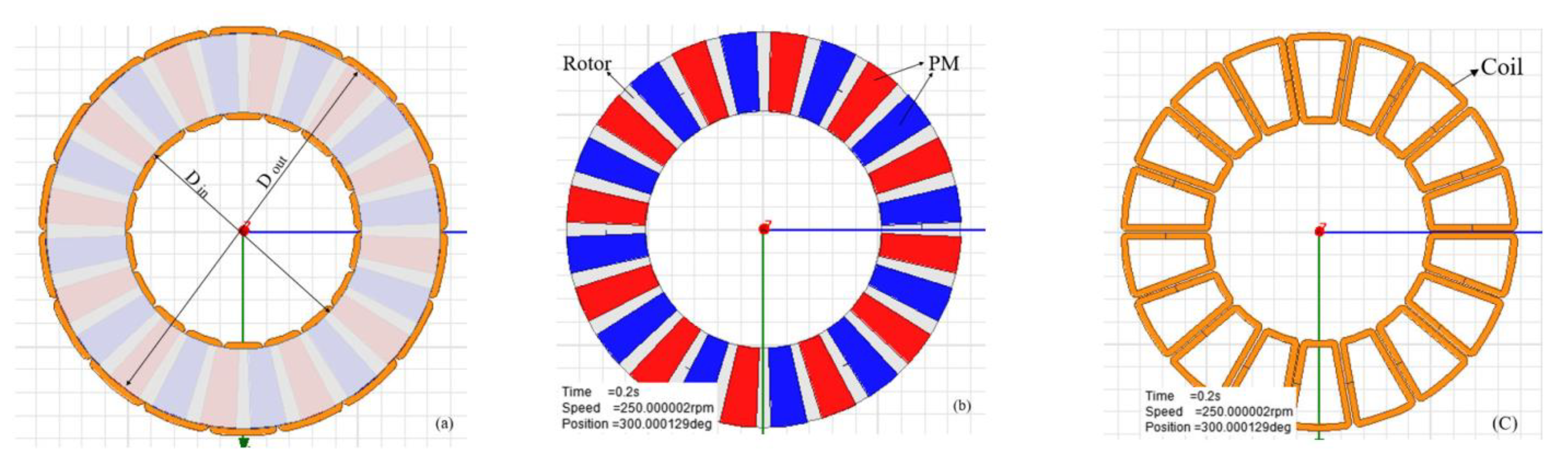
Using an NS structure for the arrangement of the magnets, the opposite poles (N, S) are facing each other. The creation of this condition in the generator permits the maximum flux linkage through the magnetic path of the machine. Later, this issue is confirmed by the results of finite element simulation. Another result of selecting the NS structure for the placement of the magnets in the under-design machine is that the leakage flux factor declines considerably. Figure 2 shows the structure of the machine components separately.
Most of the research on the design of the AFPM has not addressed inductance calculations. While the accuracy of the magnetic design of the generator in the next step confirms its validity, it depends on the accurate calculation of the inductance. It is evident that the synchronous inductance consists of two parts: the armature reaction inductance and the leakage inductance. For an air core (iron-less) stator, the magnetic saturation of the rotor disks with surface-mounted magnets is negligible. The inductance of the axes d and q are equal in the machines with magnetic symmetry. So, the armature reaction inductances for the two axes d and q are given by [9,30]:
L a d = L a q = m 1 μ o   1 π ( N p h   k w P ) 2 ( R o u t 2 R i n 2 g )
where Rout and Rin are the outer and inner radii of the machine, respectively, and Nph is the number of winding turns per phase. g’ expresses the equivalent air gap at the axes d and q for the surface-mounted magnet structure which is redefined as [9]:
g = 2 ( ( g + 0.5 L p m ) + L p m μ r r e c   )
where Lpm is the axial thickness of the permanent magnet and μ r r e c is the reversible magnetic permeability. The leakage inductance is also represented by the summation of three components: the slot leakage flux inductance, the leakage flux inductance in the end winding, and the differential leakage inductance, which is expressed as follows:
L l = L 1 s + L 1 e + L 1 d = 2 μ o N p h 2 L i P q   λ 1 s + L e L i λ 1 e + λ 1 d
where L i is the active length of a coil that is equal to the radial length of the PM, q is the number of coil arms per pole per phase (equivalent to the number of slots), Le is the average length of the single-sided end connection, L1s and λ1s are the inductance and Specific permeability for leakage flux around the radial areas of conductors, L1e and λ1e are the inductance and specific permeance for the leakage flux about radial portions of conductors (corresponding to slot leakage in classical machines), respectively, L1d and λ1d are the inductance and specific permeance for the leakage flux about the end connections, respectively, and L1d and λ1d are the inductance and specific permeance for the differential leakage flux (due to higher space harmonics), respectively. It is difficult to derive an accurate analytical expression of λ1e for a coreless electrical machine. The air gap’s specific permeances λ 1 e and λ 1 d can roughly be estimated from the following semi-analytical Equation [9]:
λ 1 s λ 1 e 0.3 q
  • Losses and Efficiency
In an AFPM iron-less machine, the major losses are copper and eddy current losses. For a coreless AFPM machine, a copper loss is calculated from the following equation:
P c u = m R   I a 2
where R and Ia are the resistance and phase current of the stator, respectively, and m is the number of phases.
In an AFPM machine with a coreless stator, the winding is directly exposed to the air gap’s magnetic field. The motion of permanent magnets in the vicinity of the coreless winding produces an alternating field through each conductor and an eddy current is induced. The loss due to eddy currents in the conductors depends on both the geometry of the wire cross section and the amplitude and waveform of the flux density. Regardless of the tangential component of the field, the eddy current losses in the stator winding can be calculated for round conductors as follows [9,11]:
P e d d y = π 2 3   σ ρ   f 2 d w 2 M c u B z 2 η d
where dw is the conductor diameter, σ is the electric conductivity, ρ is the conductor-specific mass density, Mcu is the mass of the stator conductors without insulation and end connections (effective coil mass),   f fis the stator current frequency, Bz is the axial components of the magnetic flux density, and η d is the distortion coefficient which is 1 for the eddy current under a sinusoidal flux density.
The effective weight of the coil, which is directly exposed to the rotor magnetic field, plays an important role in the determination of the eddy current losses. So, the mass of the stator radial conductors can be given as follows:
M c u = ρ m   a w N p h ( π   d w 2 4 ) ( 2 L i )
where aw is the number of parallel paths of the coil.
Finite element simulations show that the mechanical losses, such as friction in the bearings and windage losses, can be neglected in the design of the AFPM machine. So, the efficiency of the machine reduces to:
η = P o u t P o u t + P c u + P e d d y
where Pout is the output power, Pcu is the copper loss, and Peddy is the eddy current loss of the machine.

4. Overview of Elitist Genetic Algorithm Application in Wind Generator Design

The design of an AFPM machine with maximum efficiency, a minimum magnet weight, and maximum induced voltage is an optimization problem with several aspects. It can be formulated in the form of a single objective function with multiple constraints. The machine design parameters are not independent variables and there are nonlinear relationships and interactions between them. These include the simulation variables αp, Bg, Nph, and kd. GA is a meta-heuristic algorithm that reflects the process of natural selection where the fittest individuals are selected for reproduction in order to produce offspring of the next generation. It is evident by other research that GA is a powerful optimization tool for solving nonlinear complex problems [24,31]. The problem to be solved is having inputs that transform into solutions through a process modeled on genetic evolution. The solutions are then evaluated by the fitness function in order to meet the specific objectives. GA is generally an iteration-based algorithm and if the objectives or the maximum iteration are reached, the process ends.
At first, an initial population is randomly assigned to the desired design variables and subsequently, the associated objective function is determined. Then a set of simple operators (namely reproduction, crossover, and mutation) are used to process the population and generates successive populations that improve over time. A series of experiments have been performed on algorithms combining various ideas to develop a GA by which the global optimum of functions is obtained effectively [32]. As a result, in some cases, they are controlled by a decreasing function of generation, a Genetic Algorithm using remarkable mutation rates and population-elitist selection, whose performance is superior to that of the traditional GA. This method is based on the conservation of the most appropriate corresponding gene of the previous generation and the random selection of the corresponding pair. Accordingly, the elitist algorithm is used to solve the current machine design problem. The flowchart of Figure 3 illustrates the procedure of genetic algorithm optimization.

4.1. Objective Function

The definition of the objective function in the process of optimizing electric machine design depends on the type of machine and type of application. Since the purpose of this paper is to present a comprehensive approach to the design and modeling of an AFPM generator with maximum efficiency and a minimum permanent magnet weight, while producing a maximum induction voltage as well as achieving a full sine voltage wave form. Considering the above conditions, the objective function for the current problem is defined as described in (25). After gaining per unit, efficiency (η), thickness of the magnet (Lpm), and induction voltage (Epk), which are the objective function components, the optimal weighting factors must be assigned to achieve the design targets. Considering the above, the final objective function is proposed as follows:
Maximize ,   F o b j p u k d ,   B g ,   α p ,   D o u t ,   N p h = ( W 1 × η ) + W 2 × 1 L p m + W 3 × E p k
where W1, W2, and W3 are the corresponding weight coefficients that are chosen based on the design requirements and goals.
Fobj is strongly influenced by the Equations (8), (11) and (17). These equations are considered in this article as a foundation in the current design. Influential parameters and variables of the above equations play an important role in achieving the objectives of the optimization. These parameters are described in detail in Section 5.
It is evident that weight coefficient values are very effective on the convergence of the objective function. Therefore, by considering the design conditions and the given priorities, the best values for the weighting coefficients can be obtained by ranking the importance of an in-wind generator design with due attention to the expert ideas, and trying these values for the pilot case not only to lay down the problem conditions, but also to have strictly accurate and absolute and correct results. These schemas are compared due to the decision maker’s weighting, potentially masking search limitations [23]. Following such a process, the optimal values for the weight coefficients of W1, W2, and W3 for the current optimization are determined equal to 0.6, 0.2, and 0.2, respectively.

4.2. Optimization Constraints and Limitations

Some of the design parameters of the generator are inherently within a narrow range of variation and others may not change much due to mechanical and structural constraints. Under this kind of circumstance, simultaneous with the evolution of the genes that optimize the objective function, the constraints and limitations should be satisfied too. These constraints are defined in terms of specific conditions that are explained on a case-by-case basis for the design process.
For instance, the arc-to-pole ratio (αp) is considered to be in the range of 0.57–0.75 to have the minimum leakage flux and to create a sinusoidal flux density. Values above 0.75 for αp can lead to a magnetic short-circuit in the rotor [8].
Due to the increase in the length of effective air gap in coreless stator machines, the air flux density will be slightly less than the stator core type so that, in the core type, the flux density can reach 0.9 Tesla. However, in coreless stator type this value does not exceed 0.65 Tesla. Therefore, a maximum value of 0.65 Tesla can be considered for the upper bound of Bg [12].
As it is common practice in an AFPM generator design, the ratio of the inner to outer diameter is named Kd. It is worth mentioning that by increasing Kd, the effective weight of the machine will decrease; as it decreases, the torque equivalent to the generator increases. Therefore, it can be set from 0.6 to 0.75 [5,6].
Since one of the goals of this optimization is to achieve maximum efficiency, one of the most important factors that can be effective is to reduce losses. In predefined constant power, the generator loss is directly related to the phase current and resistance quantities. By increasing the number of turns per phase, not only does the phase inductive voltage rise, but also the amount of current decreases. This means a reduction in the losses and results in increased efficiency. Therefore, considering the optimization objectives, the number of turns per phase can be considered in greater quantities than conventional designs.
MATLAB R2021a (The MathWorks, Inc., Natick, MA, USA) was used to program the Elitist Genetic Algorithm (EGA). The control parameters of the genetic algorithm are optimized by conducting an exhaustive search in the full range of variations that have been used in previous applications. The optimal control parameter values of the genetic algorithm for this application are presented in Table 3.
In addition, a sample of convergence characteristic of the objective function (Fobj) is shown in Figure 4.

5. Comprehensive Design Method

In this section, the method used in the overall design of the machine, including the selection of the number of coils and poles, is presented. Generator rotational speed is proportional to wind speed and affected by the turbine characteristics. On the other hand, the relationship between the synchronous speed, frequency, and the number of poles on the machine is known well. So, one of the aspects, which is considered in this comprehensive design approach, is determining the number of generator poles according to the wind speed. For low wind speeds, the performance of small wind turbines is in the frequency range of 10–70 Hz [29]. Therefore, a range of 20–32 poles can be considered for low-speed wind generators. The number of stator coils of a three-phase machine depends on the number of poles [8]. Non-overlapping concentrated coils are provided as a stator design method for this machine [15].
Considering the mechanical limitation and constraints, as well as the presumptions and the proposed comprehensive design method, the variables and their ranges are presented in Table 4.

6. Finite Element Analysis and Results

Finite Element Method (FEM) analysis is performed to evaluate the validity of the optimal design procedure presented in previous sections. Three-dimensional finite element analysis is used to analyze the sinusoidal induction voltage and flux density throughout the machine, and precisely determine the inductance value of the coils. A 3-D FEM of the ironless AFPMWG is simulated using ANSYS Maxwell 16.0.2 (ANSYS, Inc., Canonsburg, PA, USA). The EGA-optimized parameters shown in Table 5 are the basis of the finite element simulation model.
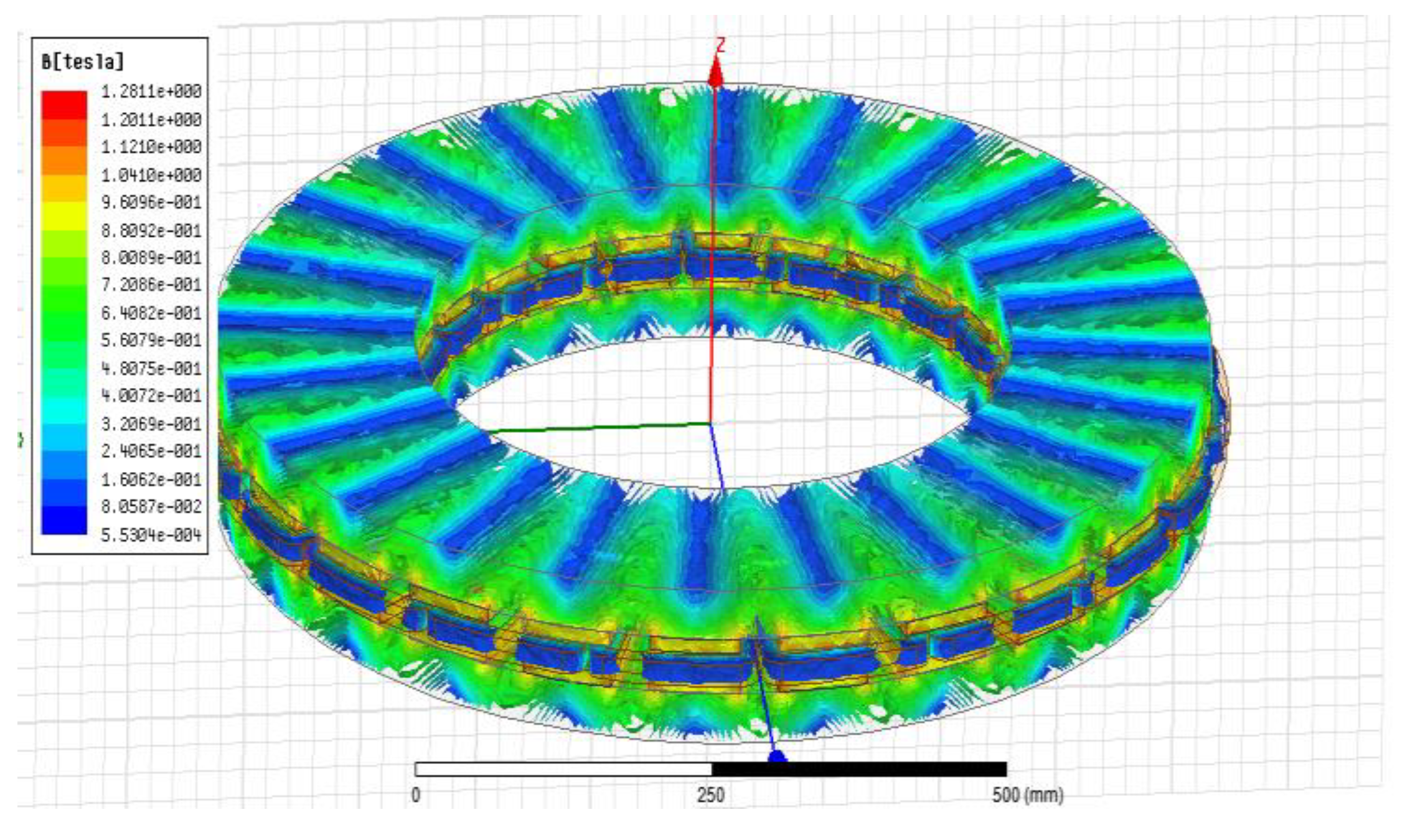
The accurate calculation of the rotor disk thickness is performed by the proposed design approach. Finite element analysis confirms there is not a magnetic saturation phenomenon, nor the related critical thermal losses. In the static magnet analyses, the 3D-FEM model of the designed wind generator has been developed and a sample of the results is visually presented in Figure 5.
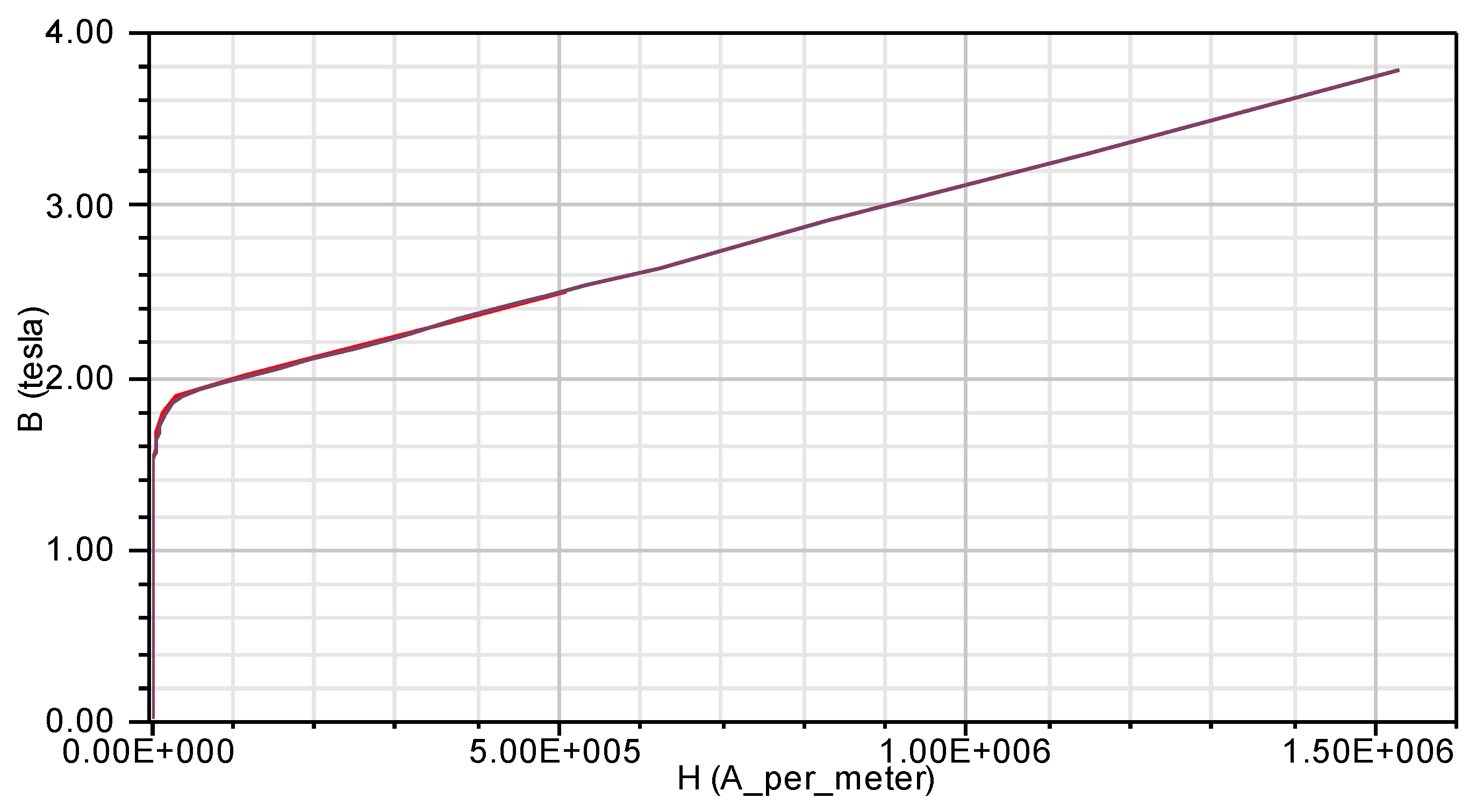
Given the figure, it is clear that the maximum magnetic flux density in the rotor discs is slightly lower than the knee point and the saturation level. Achieving the optimum rotor disc thickness results in the absorption of the maximum flux density, while magnetic saturation does not occur in the rotor discs. The alloy considered as the constituent of the rotor disc is the M19-29G, with a nonlinear behavior whose B–H curve is shown in Figure 6.
The characteristic curve of this alloy indicates that the knee point occurs at 1.85 Tesla. In fact, the maximum absorption capacity of the magnetic flux density before reaching the non-linear part of the curve (saturation) is 1.85 Tesla. Due to the magnetic flux density distribution in the rotor discs, as shown in Figure 5, the disc thickness is designed to provide the maximum permissible flux density, optimizing the weight of the discs, reducing the total effective weight and the inertia of the machine, as well as making the start of the machine easier.
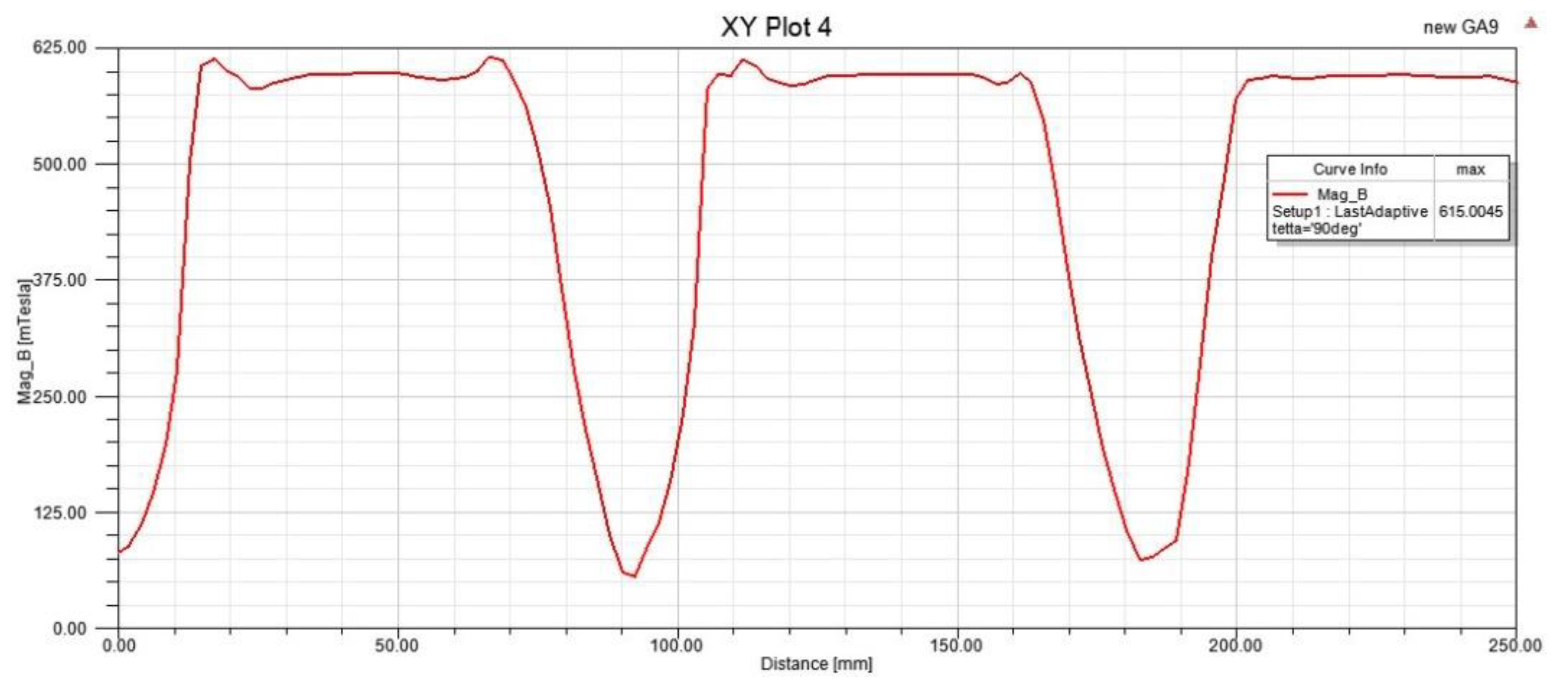
Figure 7 shows the distribution of the air gap flux density over the mean radius of the machine, which is the cogging torque, and the ripple flux percentage is zero. The air gap flux density value measured in the finite element equals 0.625 Tesla.
The analysis of various synchronous generators illustrated that in the permanent magnet type, due to the absence of the excitation coil in its rotor, the generator power factor cannot be adjusted by the excitation current and the related rotor winding equal reactance is ignored. Therefore, the power factor is affected by the connected load of the generator. In most studies, the power factor of permanent magnet machines is considered to be close to 1 under the Resistive-Inductive (RL) load.
The 3-phase induction voltage of the generator is shown under the RL load with a power factor = 0.95 in Figure 8. It is evident by the results that the generator has a sinusoidal output voltage.
The results of the 3D FEM transient analysis are given in Table 6 and compared with the fundamental component of the analytical results. The results confirm there is a high consistency between the FEM and analytical results.
In addition to comparing the analytical and finite element results in Table 6, a comparison of the results of the coil inductance and its leakage inductance is also performed in the finite element magnet analysis.
The ironless machine’s inductance in the analytical model cannot be calculated due to the insignificance of the PM leakage flux. It is evident that the exact amount of inductance can be calculated by finite element analysis. Given the difference between the inductance values, which are determined using the analytical and the finite element methods, the inductance value of the PM leakage fluxes is approximately 2 mH. Therefore, the flux linkage coefficient of Kpm = 0.93 is achieved. This small amount of flux leakage coefficient is not only acceptable but excellent for an ironless machine. The linkage phenomena and leakage flux lines for the two pairs of poles and two coils of stator can be seen in Figure 9. It is clear that most of the flux lines are mutual and cross the desired magnetic path.

7. Conclusions

In this paper, an EGA optimized approach is proposed to design a gearless AFPMWG generator for application as a wind turbine generator. For an applied design, it is essential to pay careful attention to the wind speed distribution and wind turbine characteristics in its zone of operation. The optimization objective function consists of reducing the weight of the permanent magnets, increasing efficiency, and achieving maximum sinusoidal voltage. In this paper, a detailed rotor core design and precision machine inductance calculations have been considered.
The application of the proposed approach for Iran’s climatic conditions has led to a 30 kW, 250 rpm AFPMWG, with two rotor discs and a coreless stator with optimized parameters. This generator is validated by the three-dimensional finite element method. The results show that the density of the air gap flux was without ripple and cogging torque, and the maximum inductive voltage was achieved in the form of a full sine wave. FEM simulation confirms that the proposed EGA approach created a careful design with a maximum error of 1% in determined values. All of the above has been achieved in maximum efficiency and with a minimum weight compared to a similar design.
The weight obtained for permanent magnets was, on average, 30% less than for the AFPM machines designed, which have a similar rating power [11]. This advantage is gained by considering the magnet thickness as a design objective. In this paper, a new method for the detailed calculation of leakage flux is proposed for the first time, and also a determination of the related coefficient is presented for this application (Kpm = 0.93). The value of the coefficient calculated by the analytical formulation is also validated via the FEM results.

Author Contributions

Conceptualization, O.S. and A.B.; Methodology, O.S. and A.B.; Software, O.S. and A.B.; Validation, O.S. and A.B.; Formal Analysis, O.S. and A.B.; Investigation, O.S., A.B., and B.P.; Writing—Original Draft Preparation, O.S., A.B. and B.P.; Writing—Review & Editing, O.S., A.B. and B.P. All authors have read and agreed to the published version of the manuscript.

Funding

This work was supported in part by the University of Reading, under the Innovate UK scheme (Project No. 40844).

Institutional Review Board Statement

Not applicable.

Informed Consent Statement

Not applicable.

Acknowledgments

This publication is supported by the University of Reading. The authors would like to thank all the personnel of this university who have collaborated on this project.

Conflicts of Interest

The authors declare no conflict of interest.

References

  1. International Renewable Energy Agency (IRENA). Renewable Capacity Statistics 2019; International Renewable Energy Agency (IRENA): Abu Dhabi, United Arab Emirates, 2019. [Google Scholar]
  2. Sayigh, A. Solar and Wind Energy Will Supply More than 50% of World Electricity by 2030. In Green Buildings and Renewable Energy; Springer: Cham, Switzerland, 2019; pp. 385–399. [Google Scholar]
  3. Martin, L. Wind Energy—The Facts: A Guide to the Technology, Economics and Future of Wind Power. J. Clean. Prod. 2010, 18, 1122–1123. [Google Scholar] [CrossRef]
  4. Giannakidis, G.; Labriet, M.; Gallachoir, B.O.; Tosato, G.C. Informing Energy and Climate Policies Using Energy Systems Models. Insights from Scenario Analysis Increasing the Evidence Base; Springer: Cham, Switzerland, 2015. [Google Scholar]
  5. Polinder, H.; Pijl, F.F.A.V.D.; Vilder, G.D.; Tavner, P.J. Comparison of direct-drive and geared generator concepts for wind turbines. IEEE Trans. Energy Convers. 2006, 21, 725–733. [Google Scholar] [CrossRef] [Green Version]
  6. Ishikawa, T.; Amada, S.; Segawa, K.; Kurita, N. Proposal of a Radial- and Axial-Flux Permanent-Magnet Synchronous Generator. IEEE Trans. Magn. 2017, 53, 1–4. [Google Scholar] [CrossRef]
  7. Kim, S.; Choi, D.; Cho, Y. Design and Analysis of Axial Flux Permanent Magnet Generator for Direct-Driven Wind Turbines. Int. J. Power Syst. 2017, 2, 1–6. [Google Scholar]
  8. Chan, T.F.; Lai, L.L. An Axial-Flux Permanent-Magnet Synchronous Generator for a Direct-Coupled Wind-Turbine System. IEEE Trans. Energy Convers. 2007, 22, 86–94. [Google Scholar] [CrossRef]
  9. Gieras, R.W.J.F.; Kamper, M.J. Axial Flux Permanent Magnet Brushless Machine; Springer: New York, NY, USA, 2008. [Google Scholar]
  10. Choi, J.; Lee, S.; Ko, K.; Jang, S. Improved Analytical Model for Electromagnetic Analysis of Axial Flux Machines with Double-Sided Permanent Magnet Rotor and Coreless Stator Windings. IEEE Trans. Magn. 2011, 47, 2760–2763. [Google Scholar] [CrossRef]
  11. Daghigh, A.; Javadi, H.; Torkaman, H. Design Optimization of Direct-Coupled Ironless Axial Flux Permanent Magnet Synchronous Wind Generator with Low Cost and High Annual Energy Yield. IEEE Trans. Magn. 2016, 52, 7403611. [Google Scholar] [CrossRef]
  12. Zhao, W.; Lipo, T.A.; Kwon, B. Comparative Study on Novel Dual Stator Radial Flux and Axial Flux Permanent Magnet Motors With Ferrite Magnets for Traction Application. IEEE Trans. Magn. 2014, 50, 8104404. [Google Scholar] [CrossRef]
  13. Ridge, A.N.; Ademi, S.; McMahon, R.A.; Kelly, H. Ferrite-based axial flux permanent magnet generator for wind turbines. J. Eng. 2019, 2019, 3942–3946. [Google Scholar] [CrossRef]
  14. Zhao, F.; Lipo, T.A.; Kwon, B. A Novel Dual-Stator Axial-Flux Spoke-Type Permanent Magnet Vernier Machine for Direct-Drive Applications. IEEE Trans. Magn. 2014, 50, 8104304. [Google Scholar] [CrossRef]
  15. Rostami, N.; Feyzi, M.R.; Pyrhonen, J.; Parviainen, A.; Behjat, V. Genetic Algorithm Approach for Improved Design of a Variable Speed Axial-Flux Permanent-Magnet Synchronous Generator. IEEE Trans. Magn. 2012, 48, 4860–4865. [Google Scholar] [CrossRef]
  16. Arand, S.J.; Ardebili, M. Multi-objective design and prototyping of a low cogging torque axial-flux PM generator with segmented stator for small-scale direct-drive wind turbines. IET Electr. Power Appl. 2016, 10, 889–899. [Google Scholar] [CrossRef]
  17. Mahmoudi, A.; Kahourzade, S.; Rahim, N.A.; Hew, W.P. Design, Analysis, and Prototyping of an Axial-Flux Permanent Magnet Motor Based on Genetic Algorithm and Finite-Element Analysis. IEEE Trans. Magn. 2013, 49, 1479–1492. [Google Scholar] [CrossRef]
  18. Kamper, M.J.; Wang, R.; Rossouw, F.G. Analysis and Performance of Axial Flux Permanent-Magnet Machine with Air-Cored Nonoverlapping Concentrated Stator Windings. IEEE Trans. Ind. Appl. 2008, 44, 1495–1504. [Google Scholar] [CrossRef]
  19. Lim, D.; Woo, D.; Kim, I.; Ro, J.; Jung, H. Cogging Torque Minimization of a Dual-Type Axial-Flux Permanent Magnet Motor Using a Novel Optimization Algorithm. IEEE Trans. Magn. 2013, 49, 5106–5111. [Google Scholar] [CrossRef]
  20. Gen, M.; Cheng, R. Genetic Algorithms and Engineering Optimization; Wiley: New York, NY, USA, 2000. [Google Scholar]
  21. Fasil, M.; Mijatovic, N.; Jensen, B.B.; Holboll, J. Finite-Element Model-Based Design Synthesis of Axial Flux PMBLDC Motors. IEEE Trans. Appl. Supercond. 2016, 26, 1–5. [Google Scholar] [CrossRef] [Green Version]
  22. Barriere, O.D.L.; Hlioui, S.; Ahmed, H.B.; Gabsi, M.; LoBue, M. 3-D Formal Resolution of Maxwell Equations for the Computation of the No-Load Flux in an Axial Flux Permanent-Magnet Synchronous Machine. IEEE Trans. Magn. 2012, 48, 128–136. [Google Scholar] [CrossRef]
  23. Bui, L.T.; Alam, S. Multi-Objective Optimization in Computational Intelligence: Theory and Practice: Theory and Practice; Information Science Reference: Hershey, PA, USA, 2008. [Google Scholar]
  24. Jung, S.; Jung, H.; Hahn, S.; Jung, H.; Lee, C. Optimal Design of Direct-Driven PM Wind Generator for Maximum Annual Energy Production. IEEE Trans. Magn. 2008, 44, 1062–1065. [Google Scholar] [CrossRef]
  25. Xia, Y.; Ahmed, K.H.; Williams, B.W. Wind Turbine Power Coefficient Analysis of a New Maximum Power Point Tracking Technique. IEEE Trans. Ind. Electron. 2013, 60, 1122–1132. [Google Scholar] [CrossRef]
  26. Available online: https://www.satba.gov.ir/fa/regions/windatlas-%D8%A7%D8%B7%D9%84%D8%B3-%D8%A8%D8%A7%D8%AF-%DA%A9%D8%B4%D9%88%D8%B1 (accessed on 2 October 2019).
  27. Surong, H.; Jian, L.; Leonardi, F.; Lipo, T.A. A general approach to sizing and power density equations for comparison of electrical machines. IEEE Trans. Ind. Appl. 1998, 34, 92–97. [Google Scholar] [CrossRef] [Green Version]
  28. Khan, M.A.; Pillay, P.; Visser, K.D. On adapting a small PM wind Generator for a multiblade, high solidity wind turbine. IEEE Trans. Energy Convers. 2005, 20, 685–692. [Google Scholar] [CrossRef]
  29. Faiz, J.; Ebrahimi, B.M.; Rajabi-Sebdani, M.; Khan, A. Optimal design of permanent magnet synchronous generator for wind energy conversion considering annual energy input and magnet volume. In Proceedings of the 2009 International Conference on Sustainable Power Generation and Supply, Nanjing, China, 6–7 April 2009; pp. 1–6. [Google Scholar]
  30. Meessen, K.J.; Thelin, P.; Soulard, J.; Lomonova, E.A. Inductance Calculations of Permanent-Magnet Synchronous Machines Including Flux Change and Self- and Cross-Saturations. IEEE Trans. Magn. 2008, 44, 2324–2331. [Google Scholar] [CrossRef] [Green Version]
  31. Ahn, Y.; Park, J.; Lee, C.; Kim, J.; Jung, S. Novel Memetic Algorithm implemented With GA (Genetic Algorithm) and MADS (Mesh Adaptive Direct Search) for Optimal Design of Electromagnetic System. IEEE Trans. Magn. 2010, 46, 1982–1985. [Google Scholar] [CrossRef]
  32. Shariati, O.; Zin, A.A.M.; Khairuddin, A.; Pesaran, M.H.A.; Aghamohammadi, M.R. An Integrated Method for under Frequency Load Shedding Based on Hybrid Intelligent System-Part I: Dynamic Simulation. In Proceedings of the 2012 Asia-Pacific Power and Energy Engineering Conference, Shanghai, China, 27–29 March 2012; pp. 1–6. [Google Scholar]
Figure 1. Rayleigh distribution for different mean wind speeds [11].
Energies 15 03262 g001
Figure 2. Structure of ironless AFPMSG: (a) general structure, (b) Rotor and PMs structure, and (c) ironless stator.
Energies 15 03262 g002
Figure 3. Flowchart of EGA Optimization.
Energies 15 03262 g003
Figure 4. Genetic algorithm analysis and value convergence.
Energies 15 03262 g004
Figure 5. Magnetic flux density distribution in AFPMSG.
Energies 15 03262 g005
Figure 6. B–H curve of the used steel in the rotor disc.
Energies 15 03262 g006
Figure 7. Magnetic flux density distribution of the air gap for average radius.
Energies 15 03262 g007
Figure 8. Three-phase back-EMF at 250 rpm.
Energies 15 03262 g008
Figure 9. Path of flux lines in NS-type structure used in machine designed.
Energies 15 03262 g009
Table 1. The specifications of the wind turbine.
SymbolParameterValue
nmRated rotation speed250 (rpm)
RbRadius of the turbine blade5.2 (m)
ρairAir density1 (kg/m3)
Cp-maxMaximum power coefficient0.48
VwRate wind speed11.3 (m/s)
λTip speed ratio8.055
Table 2. Typical Prototype Wave Forms [17].
Modele(t) i(t) KiKp
sinusoidal Energies 15 03262 i001 Energies 15 03262 i002 2 0.5cos φ
sinusoidal Energies 15 03262 i003 Energies 15 03262 i004 2 0.5
rectangular Energies 15 03262 i005 Energies 15 03262 i00611
trapezoidal Energies 15 03262 i007 Energies 15 03262 i0081.1340.777
triangular Energies 15 03262 i009 Energies 15 03262 i010 3 0.333
Table 3. Specifications of the EGA.
ParameterValue
Initial population20
Maximum iteration1000
Probability of mergers90%
Probability of mutation3%
Probability elitist7%
Table 4. Design constraints and requirements of the ironless AFPMWG.
ParameterValue
Rated power (KW)Pout = 30
Rated speed (rpm)Nm = 250
Physical air gap length (mm)g = 1.5
Ratio of inner to outer diameter0.6 ≤ Kd ≤ 0.75
Magnet width to pole pitch ratio0.57 ≤ αp ≤ 0.75
Air gap flux density (T)0.4 ≤ Bg ≤ 0.65
Electrical loading (A/m)10,000 ≤ A ≤ 50,000
NdfeB remanent magnetic flux density (T)Br = 1.2
Number of turns per phase (Nph)500 ≤ Nph ≤ 1500
PM axial length (mm)10 ≤ Lpm ≤ 20
Table 5. Final Design Parameters of the Ironless AFPMWG.
ParameterValue
Rate power (pout)30 (kW)
Rate speed (Ns)250 (rpm)
Number of Phases (m)3
Number of pole pairs (p)12
Number of stator coils (Q)18
Physical air gap length (g)2 × 1.5 (mm)
Outer diameter (Dout)857 mm
Ratio of inner to outer diameter (Kd)0.61
Magnet width to pole pitch ratio ( α p )0.7
Air gap flux density (T)0.611 T
Electrical loading (A/m)20,000 A/m
PM axial length (mm)10 mm
Coil axial length (mm)16.23 mm
Number of turns per phase (Nph)500
Copper losses (pcu)1703 (W)
Eddy current losses in the stator winding (Peddy)794 (W)
Efficiency at rate speed (η)92.3%
Wright of PM (mpm)39.8 Kg
Induction   voltage   ( E pk )651.89 V
Table 6. Comparison between analytical results and 3D FEM results.
ParameterAnalytical Results3D FEM Results
Output power at 250 rpm (kW)3029.325
Induction phase voltage at 200 rpm (V)651.89663.5
Maximum air gap flux density (T)0.610.623
Efficiency at 250 rpm (η)92.3%92.6%
Inductances for two axes d, q, La = Lq (mH)21.319.43
Publisher’s Note: MDPI stays neutral with regard to jurisdictional claims in published maps and institutional affiliations.

