1. Introduction
With the rapid development of modern industry and economy, the power quality in the distribution network is deteriorating because of numerous types of power electronic equipment [
1]. Meanwhile, with the emerging new energy distributed generation, the microgrid, and other advances, because of the poor bearing and regulation capacity of the power grid as well as the problems of low-voltage ride-through and the large number of nonlinear converter devices, reactive power, harmonics, imbalance, and other power quality issues also need to be managed. To solve these problems, the shunt active power filter (SAPF) has acquired comprehensive research and application [
2,
3]. By injecting a compensation current with an equal magnitude to the reference current but with the adverse phase, SAPF can ensure that the grid current has the unit power factor and no distortion [
4]. Unlike the passive power filter (PPF), which is sensitive to component parameters and prone to resonate with other loads in the grid, the SAPF provides a flexible and effective solution to common power quality issues, such as reactive power, harmonics, and imbalance [
5,
6].
The current research focus for SAPFs concentrates on the control strategy [
7,
8,
9,
10] and harmonic detection methods [
11,
12], and considerable related research achievements have been obtained. By contrast, research on the negative effect of SAPFs on the power grid attracts relatively less attention. Although SAPFs are applied for power quality improvement, the possibility of oscillation exists in the SAPF system under certain circumstances. It may exacerbate power quality instead, which is one of the main problems faced by SAPFs in practical application. This paper divides the SAPF oscillation problems into two categories according to the difference in mechanisms.
On the one hand, switching harmonics generated by SAPFs inject into the grid and cause high-frequency pollution, interfering with the regular operation of sensitive electrical equipment. To attenuate the switching harmonics, switching noise filters are introduced, mainly comprising LC and LCL types. Unfortunately, inherent resonant characteristics of the filter can amplify the switching noise in the vicinity of resonant frequency and decrease the compensation effect [
13]. On the other hand, when the load current for SAPF contains capacitive loads, such as reactive power compensation capacitors and filter capacitors, the system may oscillate and become unstable [
14]. When SAPFs are used for new energy distributed generation or microgrid power quality improvement, these two kinds of oscillation problems are more likely to occur and cause more significant harm compared with the traditional power grid. On the one hand, the grid impedance of the microgrid is large, and the harmonics generated by oscillation lead to severe grid voltage distortion and seriously affect the regular operation of other equipment. On the other hand, there are low-voltage ride-throughs in new energy power generation and microgrids. The voltage stability is poor, so more reactive power compensation capacitors need to be installed. Once these capacitors are included in the load current of the SAPF, severe oscillation is prone to occur and does great harm to the power grid. To promote SAPF applications in new energy distributed generation or the microgrid, we must pay more attention to studies on the suppression methods of SAPF oscillation. The common ground between the two kinds of SAPF oscillation is caused by the resonance characteristics of inductance and capacitance, amplifying the specific order of harmonics and worsening the power quality. However, there are some differences between them.
The former issue is called external loop amplification in this paper because the oscillation has no relation to the control of the SAPF when common tracking control is adopted. This kind of oscillation exists in both the SAPF and other power converter systems. We can analyze LC and LCL filters together since LC filters are special LCL filters. The primary solution to this problem is introducing damping. Since passive damping induces considerable heat loss, active damping methods are a promising solution and tend to attract more attention. On the one hand, the traditional capacitor current feedback method is further researched and developed. In [
15], capacitor current-feedback active damping with the phase lead compensation method was proposed to eliminate the resonant frequency forbidden region and improve the robustness of the LCL-type grid-connected inverter. In [
16], a novel capacitor current quasi-integral feedback active damping method was provided to extend the valid damping region and improve the robustness against the grid-impedance variation. The capacitor current feedback was more suitable for constant-frequency PWM control. Still, it is not easy to apply in unfixed switching frequency control, such as current hysteresis control or current timing comparison control. On the other hand, virtual resistors [
17], observer-based [
18], capacitor voltage feedback [
19], notch filters [
20], and other active damping methods have been further investigated as well. Most of these achievements have also been obtained under a fixed switching frequency strategy. Moreover, the implementation of these methods is complex, and few papers have addressed the discrete domain stability issue.
The latter problem is called internal loop oscillation or self-excited oscillation in this paper because the origin of instability is the existence of an unstable pole in the SAPF control loop. Unlike other power converters, which mainly emit fundamental waves, the SAPF is usually a high-bandwidth harmonic current source controlled by the load current. Therefore, the control mode allows the SAPF to excite the existing parallel resonant loop in the power system. Rare in other power converter systems, this oscillation usually only exists in the SAPF system. It harms power quality greatly because the harmonics near the resonant frequency are enlarged substantially. Consequently, valid measures must be taken to resolve this problem [
14,
21,
22,
23,
24]. In [
21], a resonance damping method was proposed to restrain the oscillation; in [
22,
23], selective harmonics compensation and resonance damping strategies were combined to prevent resonance. Nonetheless, the discrete domain stability of the resonance damping method was not addressed in these papers. In [
24], a controller design method based on zero pole assignment was proposed to suppress the system’s resonance. However, the robustness verification of the system was not provided when the capacitive load parameters changed. Moreover, these previous studies only considered resistive–capacitive or pure capacitive loads on the load side. As for the more general load case, such as the common resistance–inductance–capacitance in the filtering or compensation system, these previous studies have not analyzed it. Overall, attention to this problem is still insufficient, and further research is needed.
To sum up, there are deficiencies in the previous research on the oscillation suppression method of the SAPF system. Firstly, the previous studies on two kinds of SAPF oscillation problems have been separate and independent. They have not profoundly explored the internal relationship between the two types of oscillation problems, so naturally, they cannot provide a general and unified solution to the two kinds of oscillation problems. Secondly, they have paid little attention to the system’s stability after the discretization of the oscillation solution. Finally, when establishing the SAPF self-excited oscillation model, they have only considered the pure capacitance load or resistance–capacitance load and have not considered a large number of inductance–resistance–capacitance loads in the reactive power compensation and filtering systems. To address these problems, in this study, we studied the oscillation mechanism and the related suppression strategy for the SAPF system to facilitate the safe and practical application of SAPFs in occasions such as new energy distributed generation and microgrids. To sum up, the contributions of this study are as follows:
-
![Energies 15 03125 i001]()
This study classified SAPF oscillation into two categories through comprehensive and in-depth mechanism analysis and tried to reveal the internal relationship between them; it presents a general shunt virtual damping-based SAPF oscillation suppression strategy covering the previous resonant damping method and provides the discrete domain stability criterion of the control system.
-
![Energies 15 03125 i001]()
This study proposes a composite control strategy combining selective harmonic compensation and grid-side current feedback to address the harmful self-excited oscillation problem. Simulation and experimental results showed that the proposed compound control method had a better effect of oscillation suppression and harmonic compensation than previous methods.
-
![Energies 15 03125 i001]()
More generally, by establishing a mathematical model, this study analyzed the stability of SAPF self-excited oscillation under a resistance–inductance–capacitance load. When the thyristor-switched capacitor was located on the SAPF load side, the stability of the hybrid compensation system was studied and verified theoretically and experimentally.
The structure and arrangement of this paper are as follows. Firstly, the suppression method of SAPF external loop amplification is studied. As a result, a virtual resistor in parallel with the filter capacitor method is proposed to restrain the external loop amplification, and the system’s stability is analyzed. After that, the control strategy for restraining self-excited oscillation is discussed. The resonance damping method, which is also based on the shunt virtual resistance principle and the composite control strategy, is proposed to restrain the self-excited oscillation. In particular, the situation in a hybrid compensation system was also analyzed. Finally, the related simulations and experiments considering two kinds of SAPF oscillation cases are presented to prove the effectiveness of the proposed method in this paper.
2. Restraint of External Loop Amplification
When common tracking control is adopted for the SAPF, the oscillation generated from the LCL filter can be called external loop amplification since it has no relation to the system control. An analysis of the characteristics and design of the LCL filter is omitted here since considerable research achievements can be referred to. This paper adopts timing comparison control for SAPFs because of its simplicity and robustness. In this condition, the virtual resistor method seems to be a good choice to implement the active damping to restrain the LCL filter’s resonance.
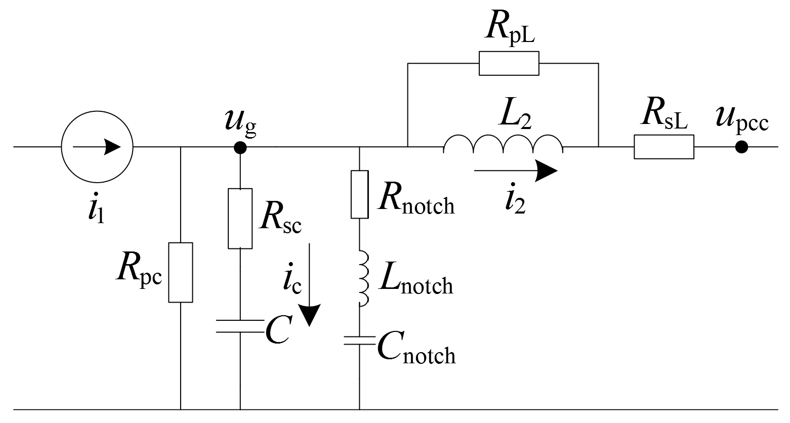
Figure 1 shows the possible positions of a virtual resistor.
represents the equivalent current source to SAPF;
is the current of the grid-side inductor
in the LCL filter;
and
are the voltage and current of filter capacitor
, respectively. There are five kinds of virtual resistors: capacitor series or shunt resistors (
), grid-side inductor series or shunt resistors (
), and notch filter active damping (
). In [
17], various virtual resistor implementation methods are provided for the generation of the reference current. In timing comparison control, the capacitor shunt resistor
seems to be a proper selection since it is simple and effective. Furthermore, it needs no differential operation to enlarge high-frequency noise. The realization method of shunt virtual resistor control is as follows:
In (1),
is the current reference of the SAPF without active damping control;
is the final current reference with the virtual resistor control method. It is necessary to sample
for this strategy. The current transfer function of the system can be obtained by:
In (2),
is grid-side equivalent inductance; the resonant frequency is
, and the damping ratio is
. It is known that the damping effect of the system is directly proportional to the grid-side total inductance and inversely proportional to
and
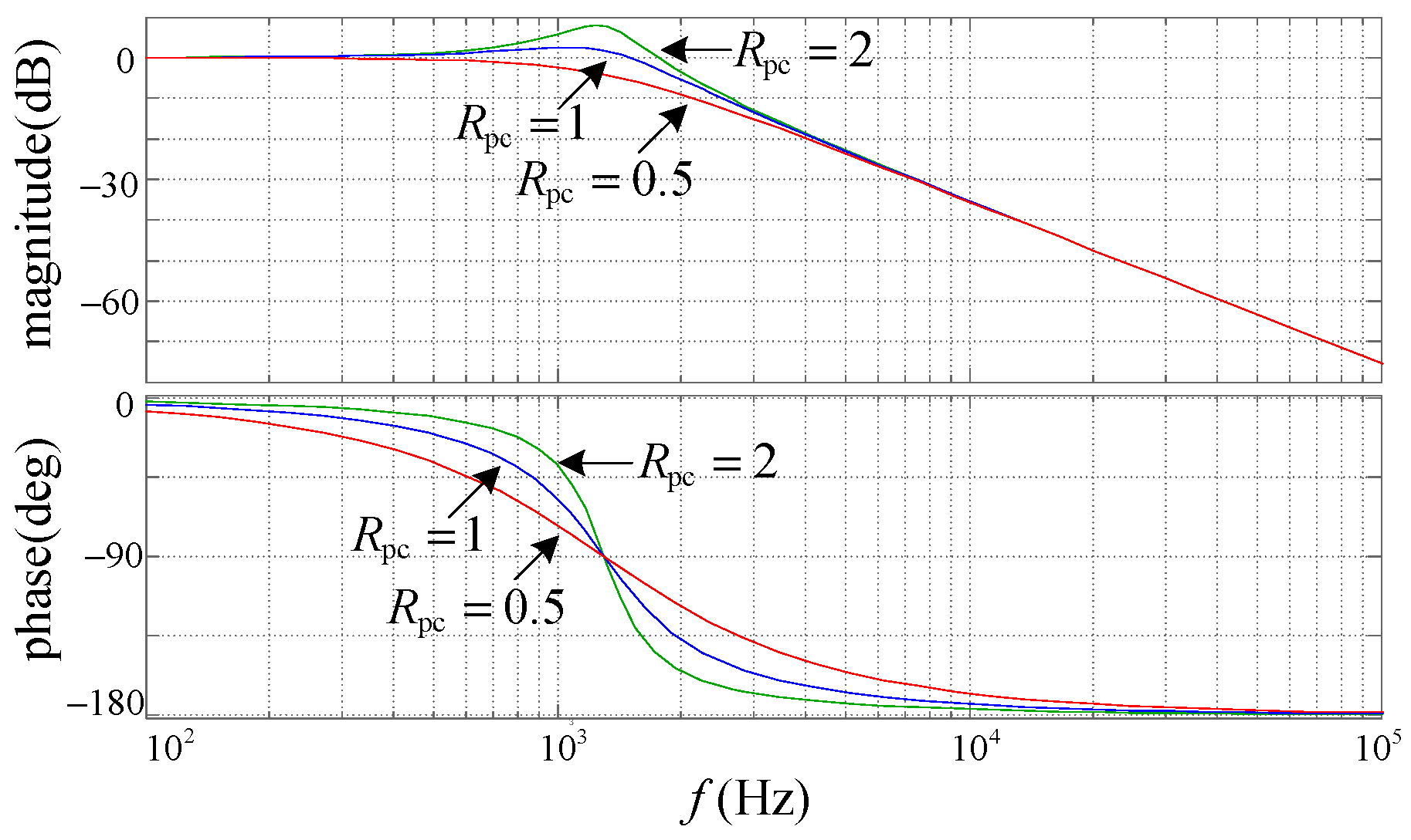
. The Bode diagram with different values of
is given in
Figure 2, and the corresponding parameters are
,
,
.
It is shown in
Figure 2 that the resonant peak was restrained obviously using the active damping method. With a decrease in
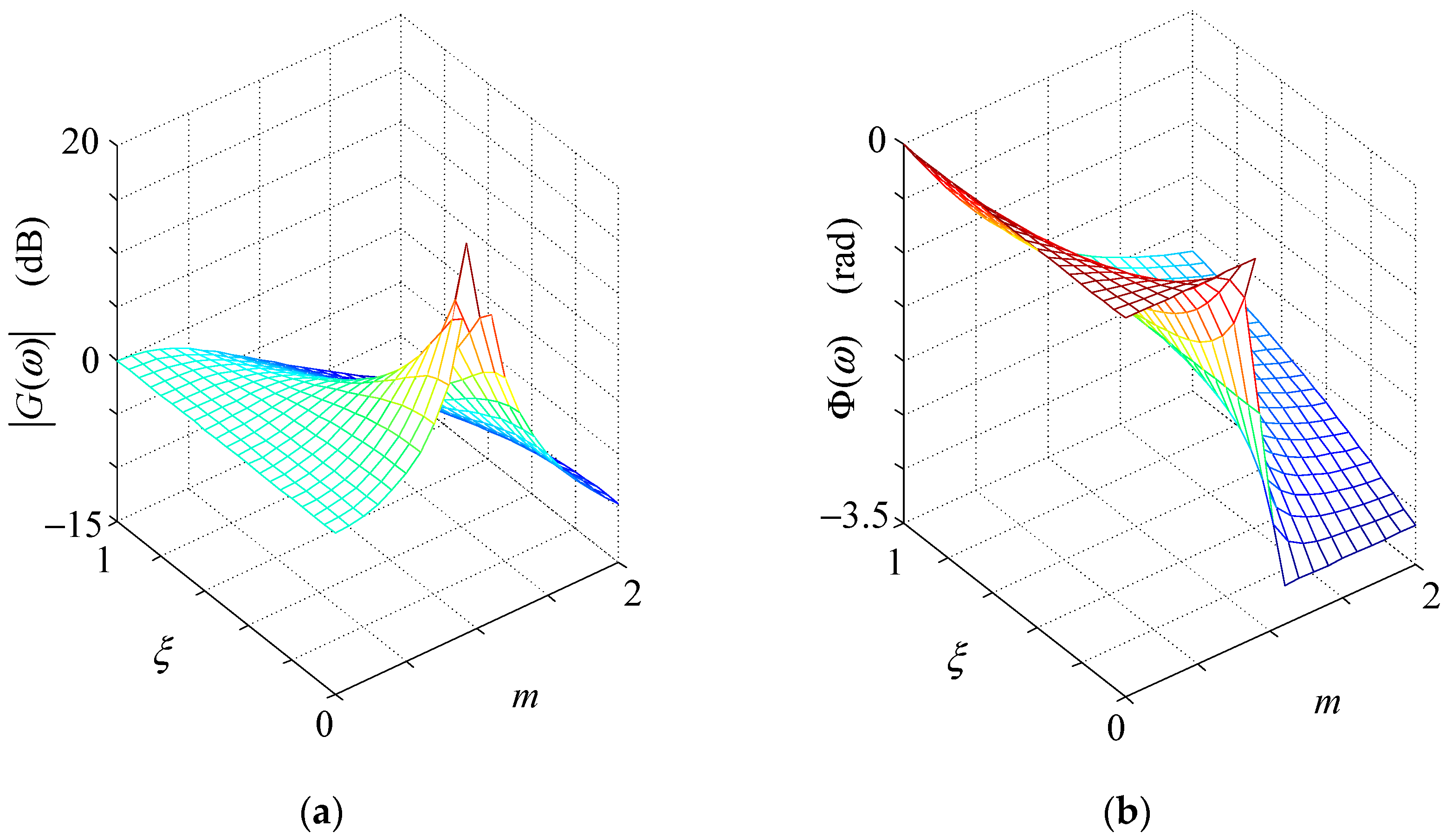
, the damping effect was enhanced. However, more phase delay was induced simultaneously. As a result, phase compensation is required in the control system in order to ensure good performance of the SAPF. When a selective harmonic control method is employed, phase compensation can easily be implemented by adding the lead correction to the phase of the specific order harmonic reference. According to (2), the frequency characteristic of the system can be acquired as follows:
Define
.
Figure 3 provides the 3D graph of the frequency characteristic. The magnitude characteristic when
deserves particular attention. It can be deduced that the magnitude at this point equals
dB. When
, the magnitude is attenuated at the resonant frequency, whereas magnitude is enlarged to a certain extent when
.
To reduce the current reference, we could only extract
, which is the harmonic part of
. This is equivalent to the shunt virtual harmonic resistor strategy with a resistance of 1/
K implemented by the equation
. Increasing
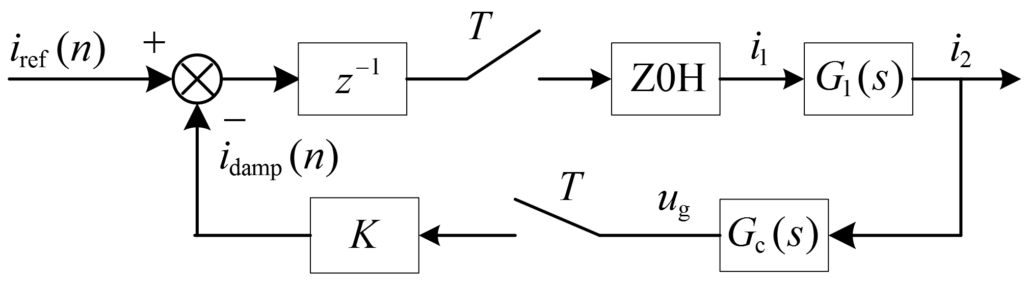
K can enhance the damping effect; however, it also weakens the stability of the control system. Next, we discuss the discrete stability domain of the system. The control block diagram of the digital current controller is illustrated in
Figure 4.
Here, the timing comparison control method was adopted for the SAPF. Because of its strong nonlinearity, the precise model for this method is rather difficult to obtain. Fortunately, we can employ a simple approximation
to simulate the delay characteristics of the system. In
Figure 4,
is the current reference calculated by the controller;
T is the sampling period of the system; Z0H denotes the zero-order holder;
represents the current transfer function from the front to the back of the LCL filter, and it contains unstable poles. The influence of the grid voltage on
can be ignored because it belongs to the disturbance category in this control loop. Define
, and the related transfer functions are provided as follows:
According to the characteristics and formulae of Z transformation, we can obtain the closed-loop transfer function as shown in (9) using (5) to (8).
On the basis of the Shannon sampling theorem, to achieve effective active damping control at the resonant frequency
, the actual sampling frequency should be greater than
, which means
. We can utilize the July criterion to analyze the stability of this three-order system. Here, the derivation process is omitted, and we directly provide the conclusion as follows:
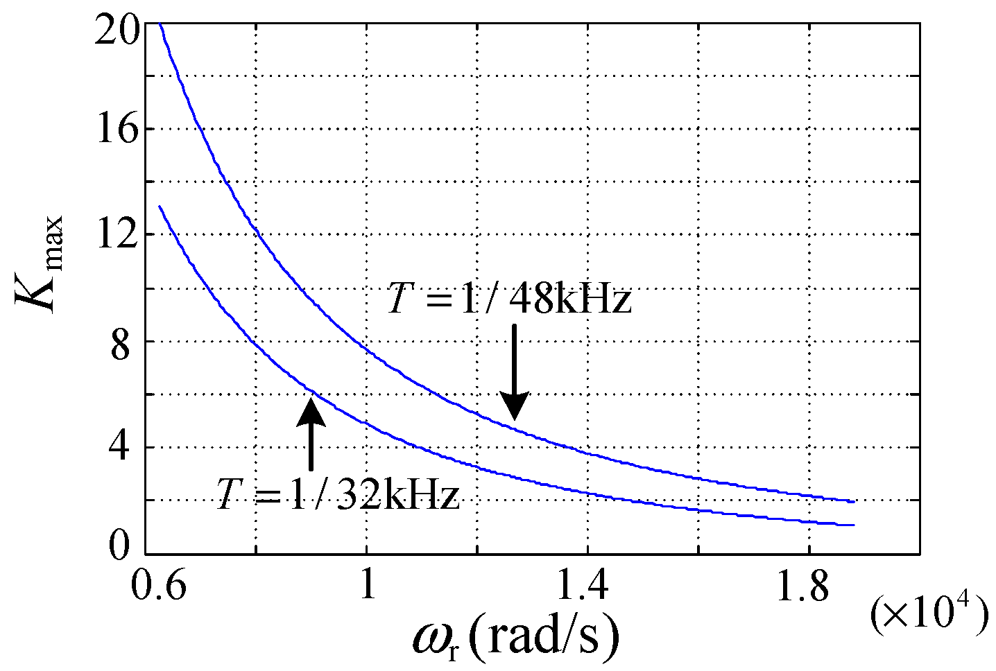
Figure 5 depicts the variation curve of
with
under the conditions of
and
. It can be obtained from (10) and
Figure 5 that
is inversely proportional to
; on the other hand, increasing the sampling frequency can improve the stability domain of the system. The selection of sampling frequency should conform to
, which means that the sampling frequency must be six times greater than the resonant frequency; otherwise, the system will be unstable.
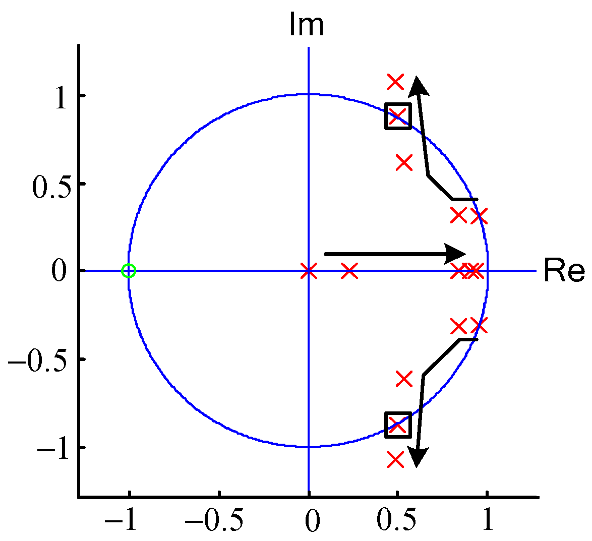
Figure 6 shows the pole diagram under the condition of
,
and
. The values of
K are 0, 1, 3, 5, and 7, respectively, and the directions of the arrows indicate the trajectory of three poles with an increase in
K. The system was experienced in three stages containing an unstable process, a stable process, and another unstable process. The poles in the box correspond to the condition of
, and the system becomes unstable. According to (10), it can be obtained that
in this condition, which is consistent with the results of
Figure 6. Some issues need to be explained here. We approximate the timing comparison control to a one-beat-delay link. Although this approximation is more or less ideal, it is effective for analyzing the influencing factors of stability and predicting the stability domain of the system. However, considering that the actual delay of the system is usually a little more than one beat, we must retain a certain margin for the result of (10) in practical applications.
3. Restraint of Internal Loop Oscillation
When the load current for the SAPF contains capacitive load, the system may oscillate and become unstable. Firstly, we analyzed the condition of no series reactor in the capacitor branch. On the one hand, much reactive compensation equipment saves the series reactor to reduce the cost; on the other hand, sometimes, we deliberately included a filter capacitor of SAPF in the detection load to control the reactive power accurately.
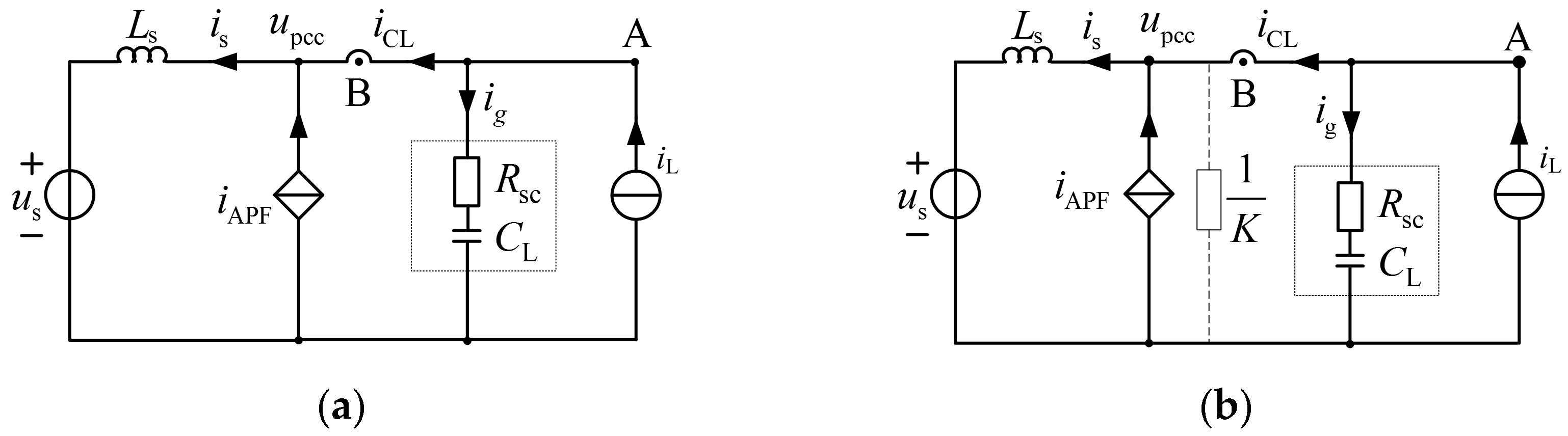
The single-phase equivalent circuit is illustrated in
Figure 7a.
is the equivalent series resistance of the capacitor;
is the load current-containing capacitor. When the detection point is located at A, the system merely experiences external loop amplification; by contrast, when the detection point is situated at B, the system will oscillate seriously because of unstable poles in the control loop. When the resonant frequency is within or near the compensation bandwidth of SAPF, with the continuous growth of reference current produced by imperfect detection and tracking features and resonance, the output current of the SAPF increases accordingly until the limiting magnitude. Hence, this kind of oscillation can occur without a harmonic source and is called self-excited oscillation. Because of the positive feedback characteristic, it causes great harm to the power quality. Consequently, effective measures should be taken to solve this problem. The selective harmonic compensation strategy in high-power applications is recommended since keeping away from the resonance point is relatively safe. Regarding low-power applications, an available method called resonance damping was provided in [
21]. In fact, it is a special form of the shunt virtual resistor method proposed above. The discrete domain stability criterion of the resonance damping system is similar to the results analyzed above in this paper. The single-phase equivalent circuit is given in
Figure 7b, and the resistance of virtual damping equals 1/
K.
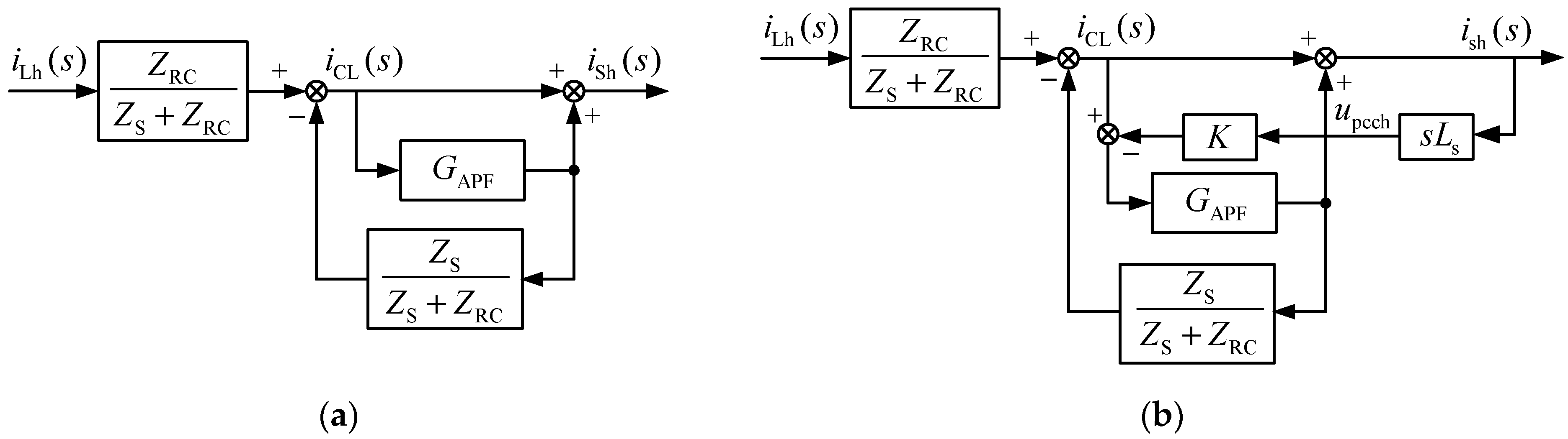
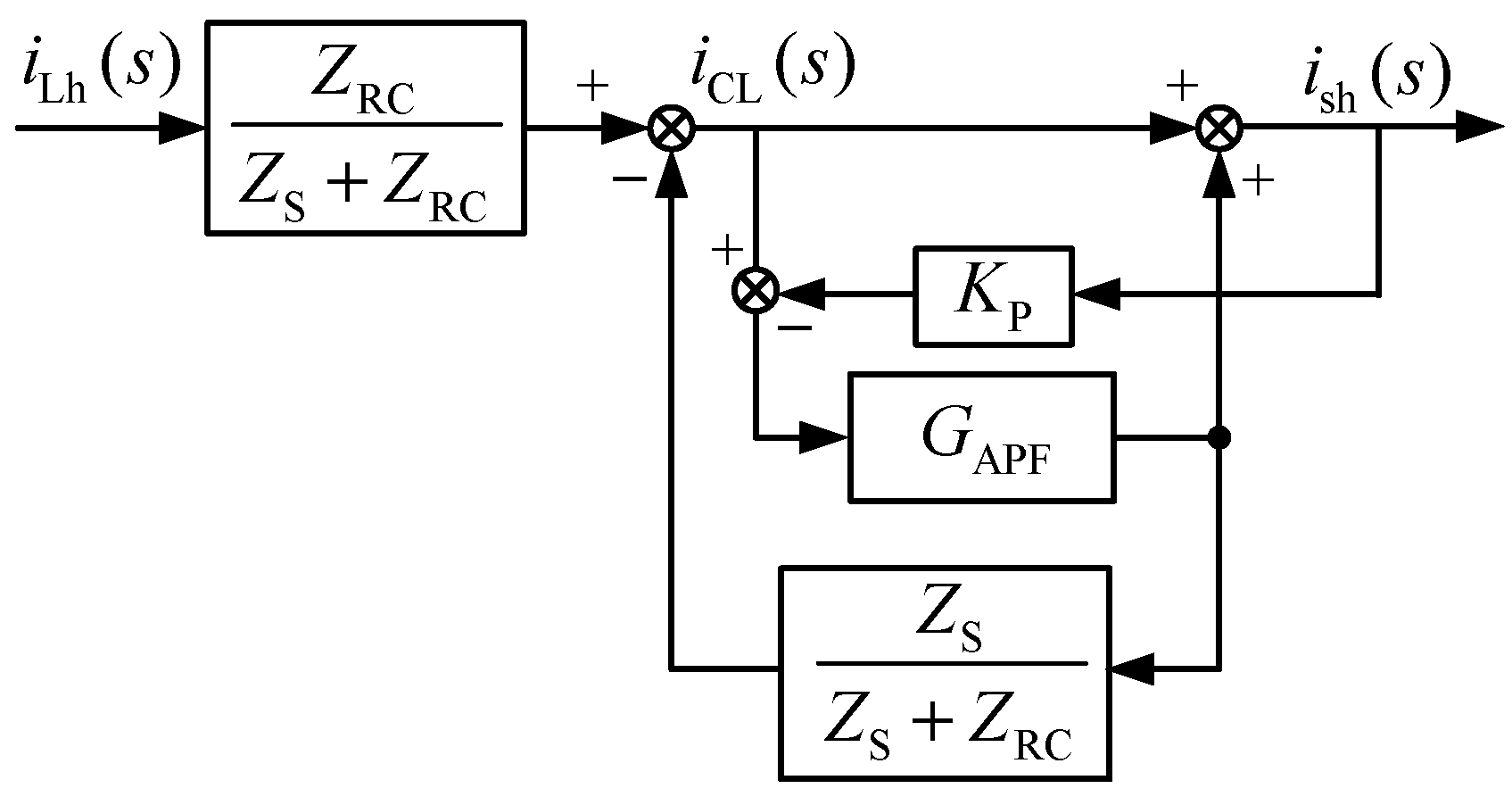
Figure 8b shows the control block diagram of the system with the resonance damping strategy.
and
are the impedance of the grid side and capacitor branch, respectively. The subscript h identifies harmonics in
Figure 8.
is the closed-loop current transfer function of the SAPF. Considering the delay of the reference calculation and the intrinsic delay of the current loop, we can obtain the following approximation:
As shown in
Figure 8a, a tracking control method was adopted, and the system was unstable owing to an unstable control loop. It can be seen in
Figure 8b that the essence of the resonance damping is the differential negative feedback of the grid-side harmonic current. Consequently, the system can become stable with improved pole distribution. Especially when the LC filter is employed, we can combine the active damping of the filter capacitor and resonance damping control. Under this condition, we can call the method unified virtual damping.
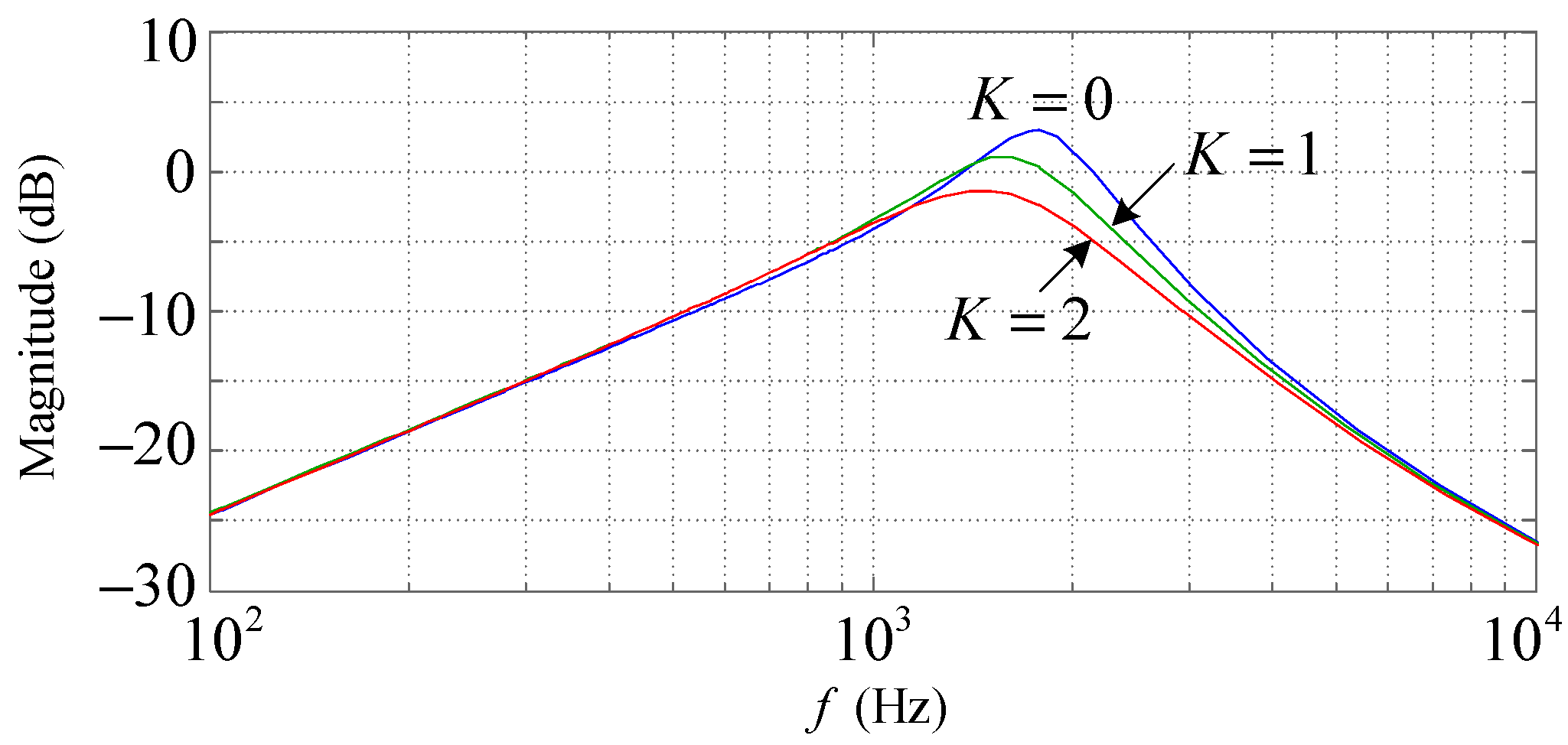
The closed-loop magnitude–frequency characteristic of the system is illustrated in
Figure 9 under the condition of different virtual resistance values. The related parameters are
,
,
, and
. It can be seen in
Figure 9 that the system’s stability is enhanced with an increase in virtual damping. The analysis of the stability region of the damping control coefficient
K can refer to the previous study on shunt virtual resistor control.
This paper provides another effective method for restraining self-excited oscillation in low-power applications. Considering that grid current feedback control can improve the distribution of poles and enhance the system’s stability, we can directly employ the proportional feedback of the grid current and combine the feedforward of load current to compose a compound control system. In this system, feedforward control undertakes the primary role of compensation and increases the system’s response speed; proportional feedback control suppresses self-excited oscillation and improves the compensation accuracy of the system. The control block diagram of the compound system is illustrated in
Figure 10, and
is the grid current feedback coefficient.
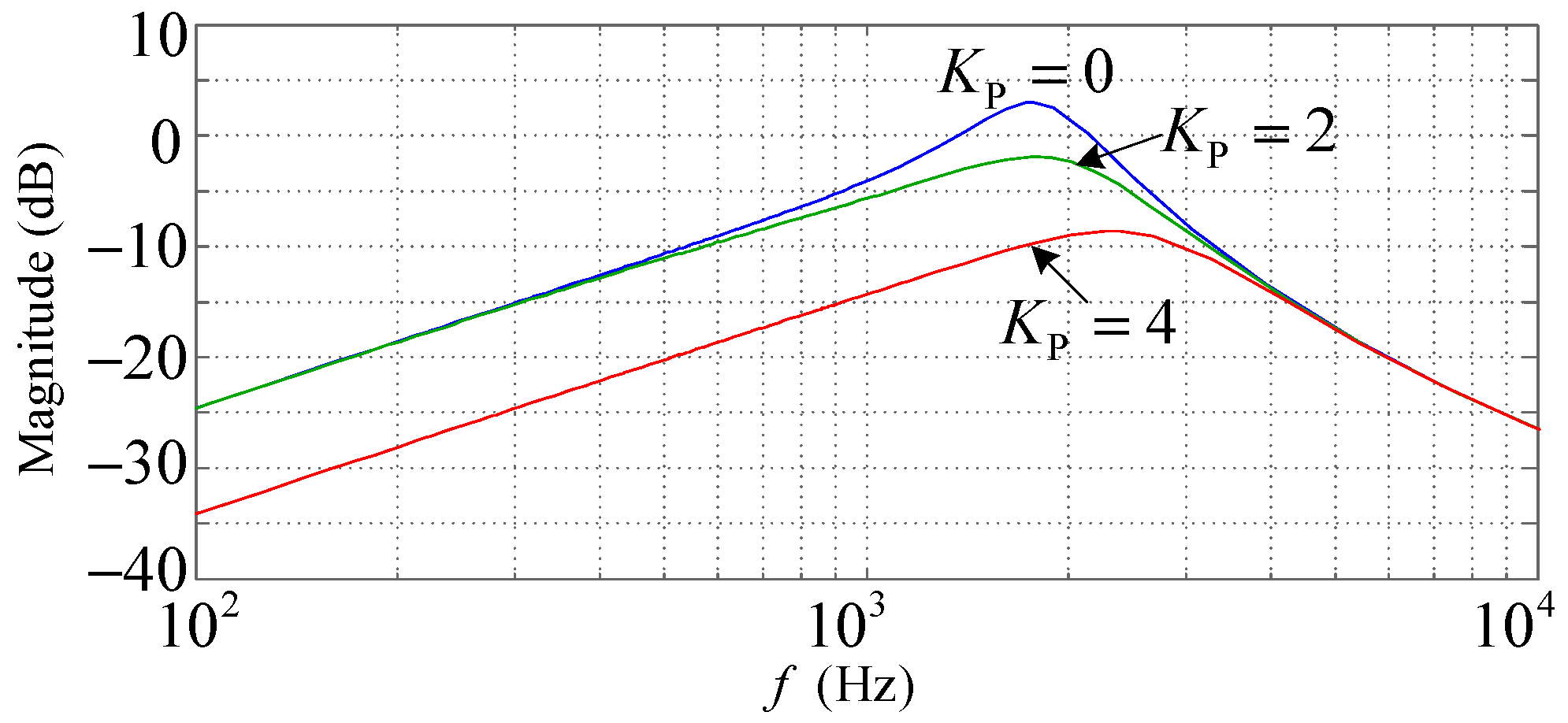
The closed-loop magnitude–frequency characteristic of the system is shown in
Figure 11 under the conditions of different
values. The related parameters are the same as those in the previous analysis. As shown in
Figure 11, the system’s stability is enhanced with an increase in
and, at the same time, the harmonic compensation effect of the system is improved. When the reference value of the SAPF equals
, according to Kirchhoff’s current law, the steady-state equation of the system is
. Proportional feedback can significantly reduce the steady-state error and improve the harmonic suppression rate, and on this point, it surpasses the resonance damping method.
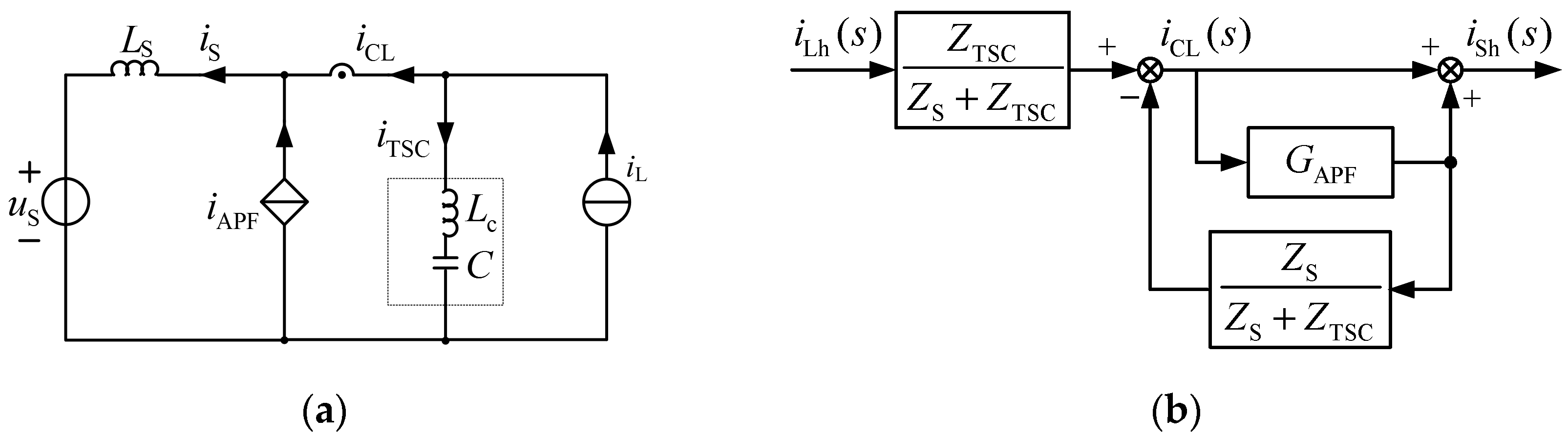
To sum up the above analysis, the system tends to be unstable under the condition of no series reactor existing in the capacitor branch. Accordingly, we can use resonance damping or the grid current feedback strategy to improve the system’s stability. Next, we will briefly analyze the condition of containing a series reactor for the capacitor branch. Taking the thyristor switched capacitor (TSC) as an example, it and the SAPF can compose a hybrid compensation system with the advantage of low cost. This system can eliminate the steady error generated from the TSC. The hybrid system’s single-phase equivalent circuit and control block diagram are shown in
Figure 12.
In
Figure 12,
is the impedance of the TSC branch;
represents the series reactor of the TSC used to prevent harmonics from injecting into the capacitor. Under normal circumstances, to restrain the third and higher harmonics, the value of the series reactance ratio is usually 12%; to suppress fifth and higher harmonics,
is typically 6%. When the harmonic is small enough, we can set
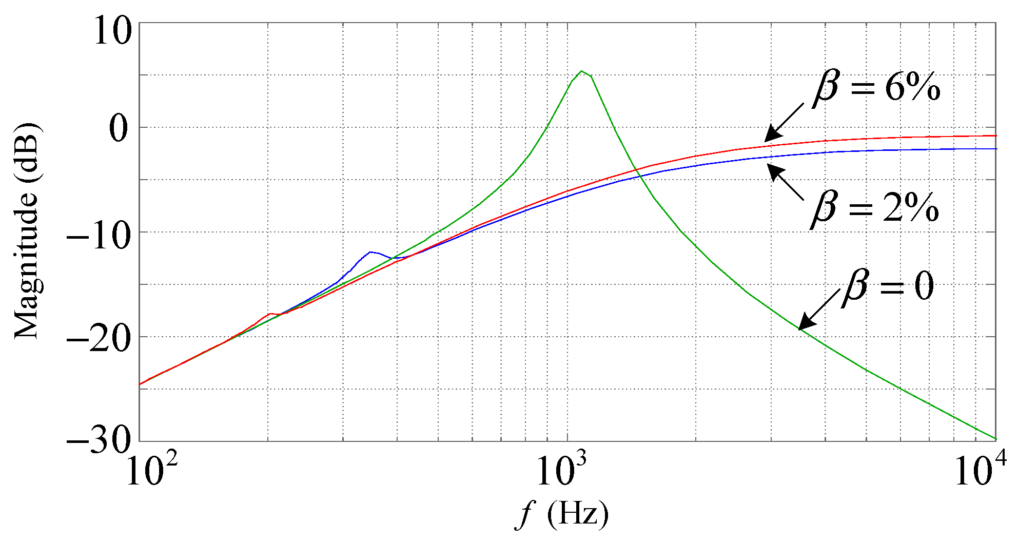
to 2%. The closed-loop magnitude–frequency characteristic of the system is illustrated in
Figure 13 in situations with different
values. The single-phase compensation capacity of the TSC is 20 kVA, which means
. Some parameters are as follows:
, the equivalent series resistance of
is
; the equivalent series resistance of the TSC branch is
. The other parameters are the same as those of the previous analysis.
As shown in
Figure 13, the system was unstable when
, which was actually the same as that without a series reactor. When
and
, although an upturned phenomenon occurred at the resonance frequency, the system was still stable and maintained satisfactory harmonics compensation performance. Thanks to the steep frequency-selecting characteristic of the TSC branch, most of the harmonic was prevented from injecting into the capacitor. Despite the possibility of oscillation still existing, the resonance band was exceptionally narrow, which means that the system was significantly secure. The higher the series reactance ratio is, the more safety is ensured as long as the resonant frequency avoids the characteristic harmonic. When we selected a series reactance ratio following established practice, such as 6%, self-excited oscillation did not occur.
4. Simulations and Experiments
The first verification group aimed at the shunt virtual resistor strategy for the LCL filter. To prove the correctness of the proposed method and the stability analysis, we carried out simulations using Matlab/Simulink software. A three-phase SCR rectifier generated the harmonic, and the resistance on the DC side was . The related parameters were , , , , and . The resonant frequency of the LCL filter was about 1.4 kHz, which can be obtained at according to (10). In one sampling period of calculating the reference, the current of the SAPF was sampled and compared with the reference twice. Using this double sampling rate control method can raise the switching frequency effectively under the premise of not improving the calculation speed of reference. Accordingly, slightly increased. However, the degree of increase was not great because the dominant sampling frequency of the damping control system was invariant.
Figure 14 shows grid current waveforms with different
K values. In
Figure 14a, the harmonic near the resonant frequency was enlarged substantially under the condition of no virtual resistor. With an increase in the
K value, resonance was well suppressed, as shown in
Figure 14b. When
K increased, the grid current waveform gradually deteriorated since the pole approached the unit circle again, as shown in
Figure 14c. In the end, the system became unstable, which is illustrated in
Figure 14d. For safety, the
value in practical applications is usually no more than half of the theoretical value.
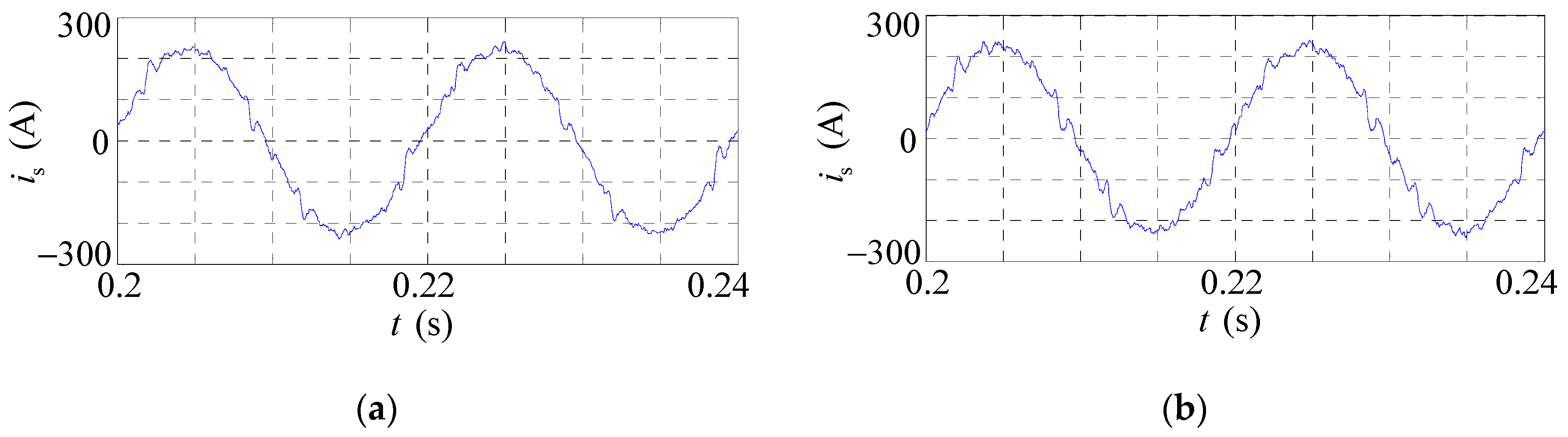
From the previous analysis, the increase in stability can be acquired by decreasing resonant frequency or raising sample frequency. Here, keeping
and the other parameters the same as those of the previous simulation, and the condition of
and
were tested, which is illustrated in
Figure 15. The simulation results show that the original unstable system becomes stable, demonstrating the stability theoretical analysis’s validity.
In order to verify the practical performance of the shunt virtual resistor method, corresponding experiments were conducted on the experimental prototype shown in
Figure 16. The related parameters were the same as those of the previous simulation. The RMS value of the grid line voltage was 380 V, and a three-phase SCR rectifier was used to generate the harmonic. The resonant frequency of the LCL filter was about 1.4 kHz.
was obtained according to (10). We employed
, and a double-sampling rate timing comparison control was adopted in the experiment.
Figure 17 provides the corresponding experimental waveforms.
As shown in
Figure 17, the resonance was significantly suppressed when introducing shunt virtual resistor control. The THD value of the grid current decreased from 8.8% to 6.2% because of the composition reduction around the resonant frequency.
Table 1 compares the grid-side current composition near the resonant frequency without and with the virtual shunt resistor. From
Table 1, the effectiveness of shunt virtual resistor control can be demonstrated intuitively.
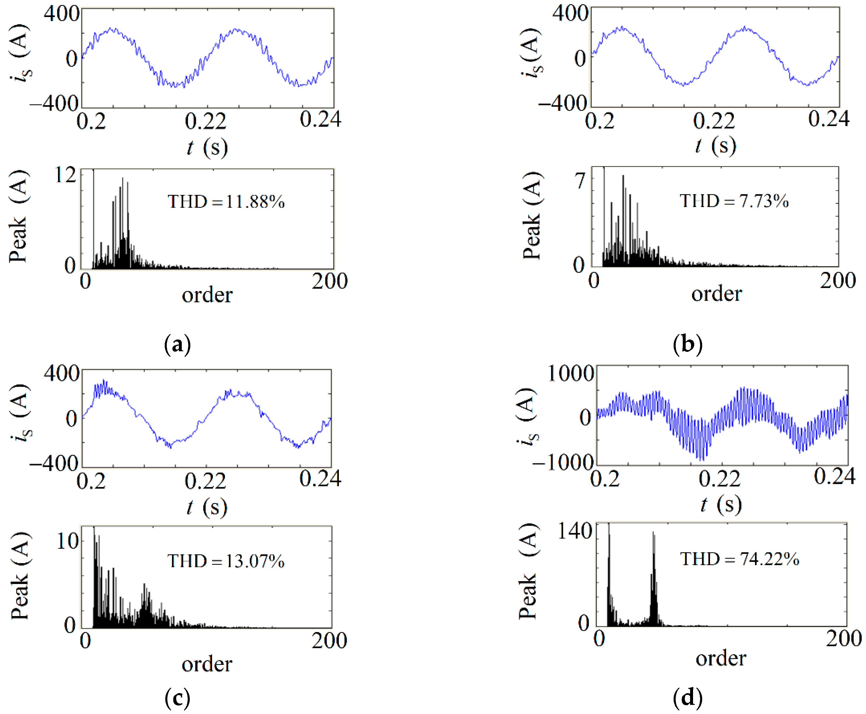
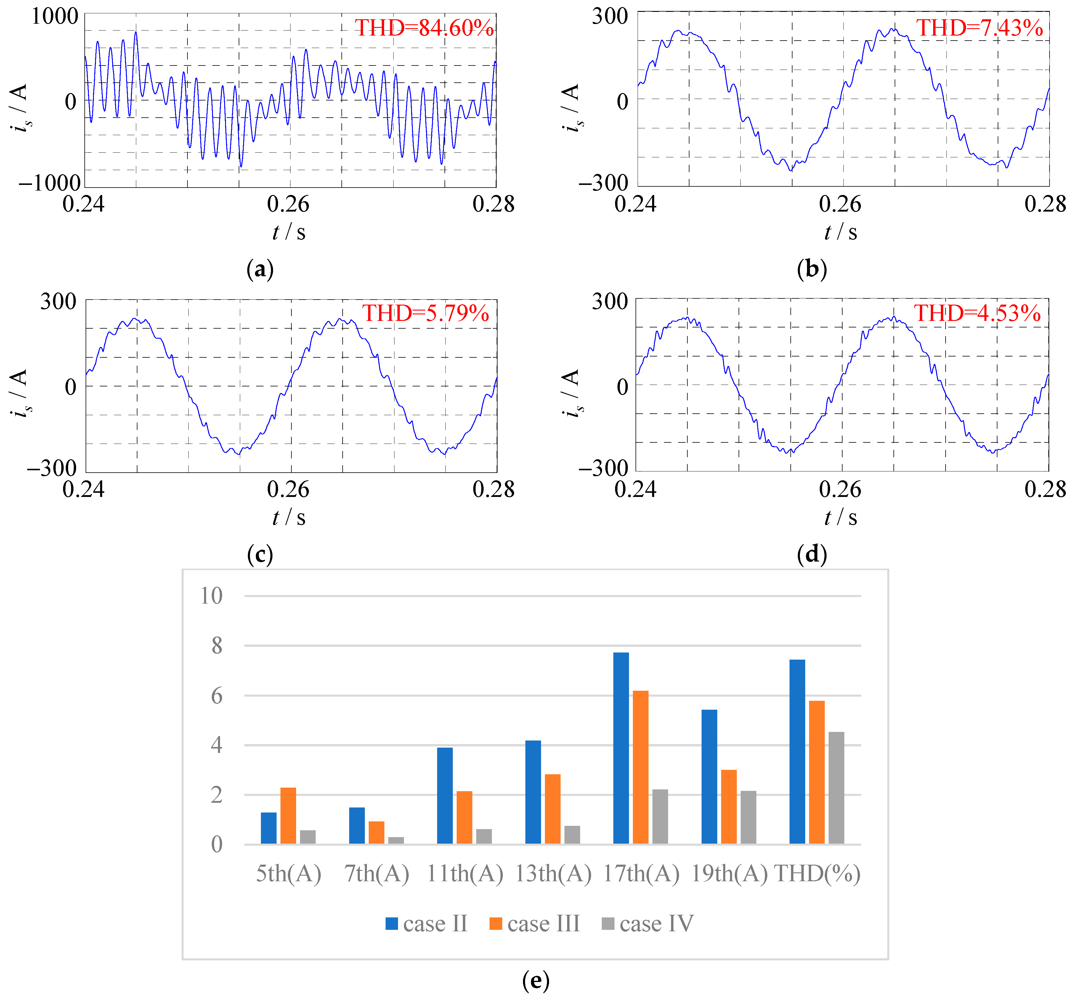
The following simulation group was used to verify the proposed restraining method for self-excited oscillation. In the simulation, the RMS value of grid line voltage was 380 V, and a three-phase SCR rectifier was used to generate the harmonic with a
resistor on the DC side. The equivalent reactance on the grid side was 0.04 mH. The capacitance included in the load was 1120 μF, and the resonant frequency of the system was approximately 750 Hz. To compare the control performance of the proposed control strategy with the other control strategies, we conducted several case simulations. For case I, the SAPF adopted the full harmonic compensation strategy. For case II, the most widely used method in engineering practice, the selective harmonic compensation strategy, was used to restrain the self-excited oscillation. The 5th, 7th, 11th, and 13th harmonics were selected to be compensated. For case III, the combination of selective harmonic compensation and resonance damping strategies proposed in [
22,
23] was used for contrast. In addition, the 5th, 7th, 11th, and 13th harmonics were chosen to compensate, and the resonance damping coefficient was 1. For case IV, the proposed combining selective harmonic compensation and grid-side current feedback control was employed in the SAPF. The 5th, 7th, 11th, and 13th harmonics were selected, and the feedback coefficient
Kp was 2. The corresponding simulation results are provided in
Figure 18 and
Table 2.
Figure 18a shows the condition of the full harmonic compensation strategy. The filtered grid current oscillated substantially, inducing massive pollution in the grid and usually causing overcurrent protection of the SAPF. The reason for the oscillation was the system’s self-excited characteristic, and the tracking compensation frequency band included the unstable harmonic order. As shown in
Figure 18b–d, the self-excited oscillation was avoided because of the adoption of the improved control strategies, and the system became stable. When the three methods were compared with each other, this study’s proposed combined control strategies achieved the grid current waveform with the highest sinusoidal degree. As shown in
Table 2, compared with the other control strategies proposed in [
22,
23], the harmonic suppression performance of the proposed combined control strategies in this study was improved, and the filtered grid current THD was only 4.53%. Meanwhile, self-excited oscillation was strongly suppressed, which verifies the validity of the proposed combined control strategy.
To verify the actual effect of compound control, we carried out related experiments on the prototype of the SAPF. A capacitor of
was in parallel with the load, and grid line voltage was adjusted to 200 V by a voltage regulator to protect the capacitor. The parameters of the LCL filter were
,
,
, and
. The load current was calculated by the grid current and
in
Figure 1. As a result, filter capacitor
C and the load-side capacitor
were both contained in
used for calculating the harmonic reference. According to the previous analysis, the system was unstable if we only used the tracking control method. In this experiment, the 5th, 7th, 11th, and 13th harmonics were selected to be compensated using the timing comparison control method, and grid current feedback was introduced. The sampling frequency was 16 kHz. The corresponding waveforms are provided in
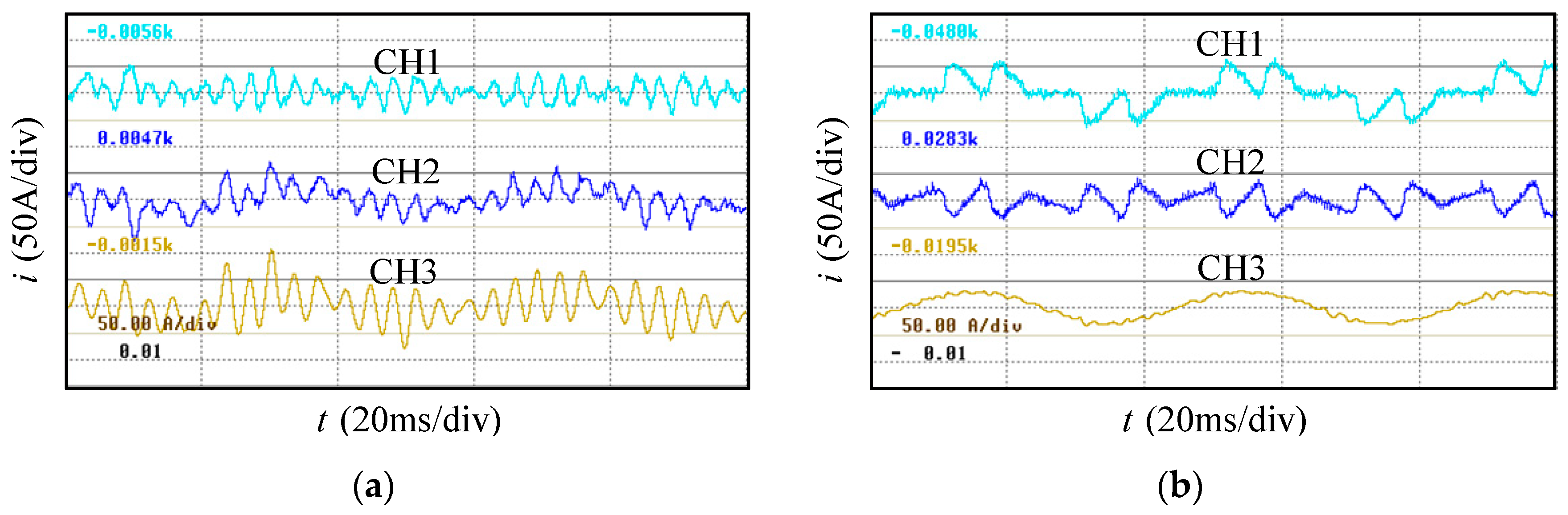
Figure 19.
Figure 19a shows the condition of only employing the tracking control. The harmonic source in the load side was disconnected, and self-excited oscillation occurred, inducing severe harmonic pollution to the grid, similar to the simulation result. The oscillation frequencies were around the 11th and 13th harmonics. In order to protect the capacitor, strict current limiting for the SAPF was employed.
Figure 19b shows the effect of compound control. It was observed that self-excited oscillation was restrained intensively, and the SAPF performed well on harmonic compensation. The grid current was approximately sinusoidal, and
Table 2 provides the specific compensation results for characteristic harmonic.
It can be observed in
Table 3 that the compensation rate of the selected harmonic reached or exceeded 90%. The 17th and 19th harmonics were also suppressed to a certain extent because of the function of the grid current feedback. The THD of the grid current was compensated from 77% to 8.5%. The overall performance of the proposed compound control strategy was entirely satisfactory.
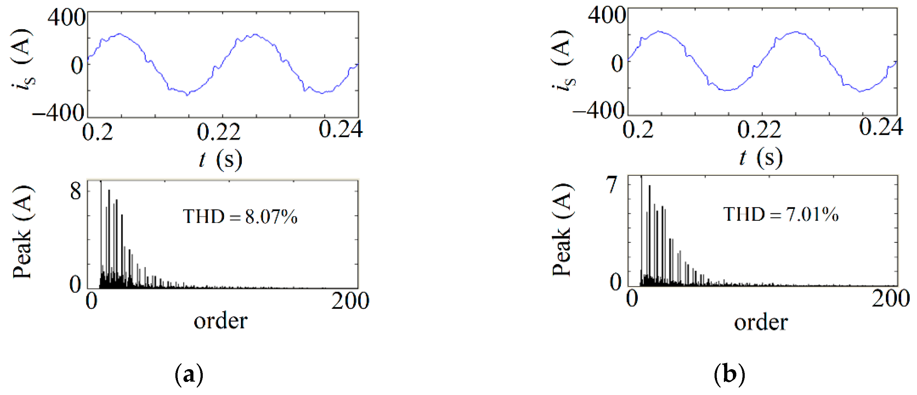
A simulation to verify the stability of the hybrid compensation system composed of the SAPF and TSC was carried out. The TSC was included in the load current used for calculating the reference of the SAPF. The single-phase compensation capacity was 24.675 kVA for TSC, which corresponds to
. In the simulation, the 5th, 7th, 11th, and 13th harmonics were selected to be compensated. We only used the tracking control method for the SAPF, and the sampling frequency was 16 kHz. A three-phase SCR rectifier generated the harmonic, and the resistance on the DC side was
.
Figure 20 shows the grid current after being compensated by the hybrid system under different values conditions. It was observed that the system was stable when both
and
, consistent with the theoretical analysis results.
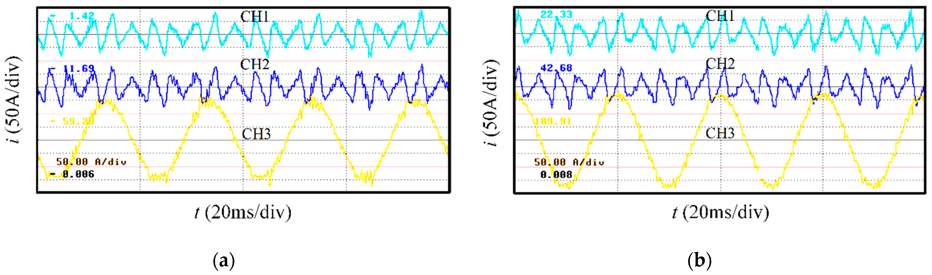
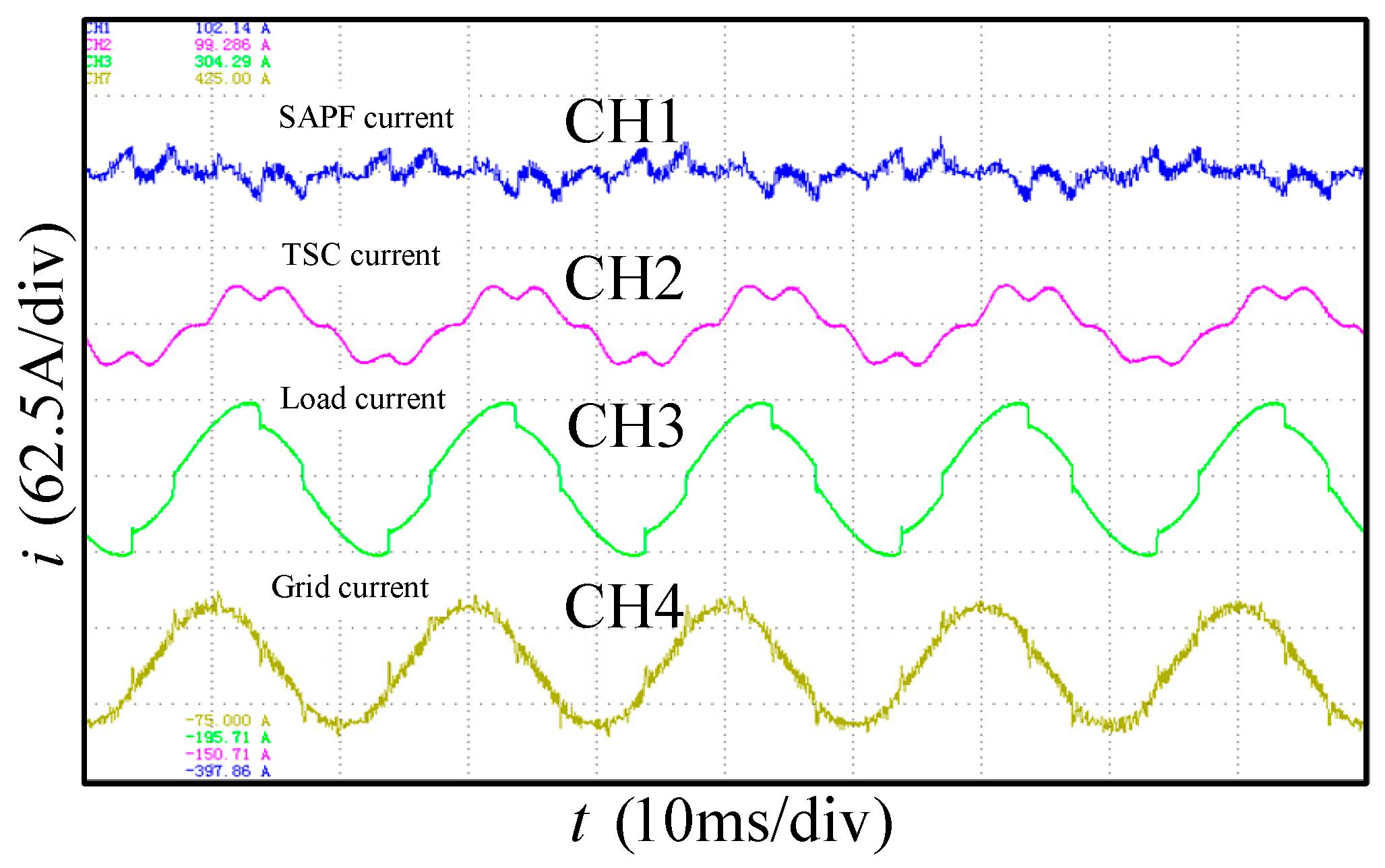
In the end, corresponding experiments were implemented on the experimental prototype. The RMS value of the grid line voltage was 380 V. On the load side, the three-phase reactors and SCR rectifiers generated controllable reactive power and harmonics, respectively. The grouping method adopted the 4-2-1 rule for the TSC, and the single-phase total compensation capacity of TSC was 24.675 kVA. The value of the series reactance ratio
was chosen to be 6% for the TSC prototype.
Figure 21 demonstrates the steady compensation performance of the hybrid system. It was observed that no self-excited oscillation occurred, and the hybrid system was stable with good compensation performance, which verifies the validity of the stability analysis of the hybrid system.
5. Conclusions
This study paid attention to the negative effects of the SAPF and the solution. On the basis of previous studies, the following conclusions were drawn.
The possibility of SAPF system oscillation under certain circumstances is a significant threat to the security and stability of the power grid. In this paper, we classified the oscillation into two categories. The first category of oscillation is caused by the resonance characteristics of the switching noise filter and can be called external loop amplification since it has no relation to the control mode of the system. The other category of oscillation, called internal loop oscillation or self-excited oscillation in this paper, is caused by the existence of capacitors in the load current for SAPF.
Both oscillations are caused by the excitation of the existing LC resonant circuit in the power grid. This study fully considered the internal correlation between the two kinds of oscillation. A general shunt virtual resistor method with the superiority of no differential operation was proposed to resolve two types of oscillation problems. We established the mathematical model of the system and obtained the stability domain of the virtual damping control coefficient according to the July stability criterion. Firstly, the sampling frequency should be higher than six times the resonant frequency to ensure the system’s stability. Moreover, the stable region enlarges with an increase in the sampling frequency and narrows with an increase in the resonant frequency or total grid-side inductance. In particular, the previously studied resonant damping strategy is essentially a special form of the virtual shunt resistance, and its stability criterion is the same as the above conclusion. Experiments with the external loop amplification inhibition showed that by the virtual damping, the THD value of filtered grid current decreased from 8.8% to 6.2% because of the composition reduction around the resonant frequency.
Self-excited oscillation does great harm to the power grid and must be restrained. This study constructed a more general self-excited oscillation model containing resistance–inductance–capacitance load situations. When no series reactor exists in the capacitor branch, the conventional load-current tracking control system tends to be unstable. We proposed a composite control strategy combining selective harmonic compensation and grid-side current feedback to resolve the problem. Using this method, we improved the steady compensation performance of the SAPF under the function of feedback. Simulation and experimental results demonstrated that self-excited oscillation was intensively restrained by the proposed method, and the compensation rate of the selected characteristic harmonic could exceed 90%. In the contrast simulation, compared with the resonant damping strategy, the proposed composite control strategy had a better oscillation suppression performance and could improve the THD of grid-side filtered current from 5.79% to 4.53%. Furthermore, when the series reactor existed in the capacitor branch, the system’s stability could be enhanced. In this study, the stability of the SAPF–TSC hybrid compensation system was studied. Theoretical analysis and experimental results showed that if we selected the TSC series reactance rate following more than 6%, self-excited oscillation could usually be avoided.


