Article

A Negative Sequence Current Phasor Compensation Technique for the Accurate Detection of Stator Shorted Turn Faults in Induction Motors

Research Centre for Nuclear Fuel Cycle and Radioactive Waste Technology, National Research and Innovation Agency of Republic Indonesia, Puspiptek Complex, Building 20, Tangerang Selatan 15314, Banten, Indonesia
*
Author to whom correspondence should be addressed.
Energies 2022, 15(9), 3100; https://doi.org/10.3390/en15093100
Submission received: 7 March 2022 / Revised: 28 March 2022 / Accepted: 7 April 2022 / Published: 24 April 2022
(This article belongs to the Special Issue Early Detection of Faults in Induction Motors)

Abstract

:
Stator faults are the most critical faults in induction motors as they develop quickly hence requiring fast online diagnostic methods. A number of online condition monitoring techniques are proposed in the literature to respond to such faults, including the signature analysis of the stator current, vibration monitoring, flux leakage monitoring, negative sequence components of voltage and current and sequence components monitoring based on the identification of asymmetrical behavior in a machine. Negative sequence components of voltage and current and sequence components monitoring are commonly considered for the identification of asymmetrical behavior of induction motors. Negative sequence current analysis is a sensitive technique for the detection of shorted turns as it directly measures the asymmetry produced by the fault. However, the technique is sensitive to other asymmetrical faults and disturbances, which can also produce negative sequence currents. These disturbances include sensor errors, inherent asymmetry and voltage unbalance. This paper provides a comprehensive investigation of the disturbances using a motor model along with experimental measurements under varying load conditions. Then, a new phasor compensation technique is explained to eliminate such disturbances effectively. This technique enables the accurate detection of even relatively small shorted turn faults, even at an early stage. The technique is tested experimentally, and a set of practical results are given to validate the methods developed.

1. Introduction

Electric motors consume about 45% of the world’s electric energy. In total, 10.3% of these are medium size (0.75–375 kW), and 0.3% of them are large size (>375 kW) motors that consume a significant level of energy and usually operate in critical applications. Among the motor types, induction motors cover a greater portion of the applications, from direct-online (DOL) grid-connected motors to electric vehicles, primarily due to their robustness, reliability and low cost. However, the failure of induction motors has a significant impact on both their running cost and the efficiency of production.
Catastrophic failure of the motors usually develops over a period of time (from seconds to days), first as a low degree of fault, which is investigated intensively under “condition monitoring” involving various electrical quantities. The faults in induction motors can be classified into five groups (Figure 1b): bearing related faults (41%), stator related faults (37%), rotor faults (10%) and eccentricity related and mechanical faults (12% in total).
Online condition monitoring and diagnostic methods are preferred to predict any incipient failures in induction motors. As the most critical faults, stator faults are commonly detected using steady-state condition monitoring.
Various online diagnostic methods are proposed in the literature, including the signature analysis of the stator current, vibration monitoring, flux leakage monitoring, negative sequence components of voltage and current and sequence components monitoring that is based on the identification of asymmetrical behavior in a machine.
Among these, the sequence components method offers a fast and reliable solution in which any unidentified unbalanced three-phase voltage or current phasors are transformed into a set of three simple independent balanced component phasors: positive sequence, negative sequence and zero sequence phasors. Moreover, sequence component monitoring provides opportunities to increase the accuracy of the results through non-idealities and non-linearity compensation techniques.
Note that the positive sequence component always exists due to the supply voltage, but the negative sequence component exists only under asymmetrical voltage supply or under motor faults. Hence, the negative sequence component is utilized to monitor the health of the machine as well as can identify the supply voltage unbalances. For example, negative sequence current monitoring can detect one of the most critical faults, stator shorted turn faults in induction motors, as an alternative to other signature analysis techniques such as stator current, vibration and flux leakage [1,2], and this non-invasive method has low computational requirements [3,4].
However, the measured negative sequence may contain inherent non-idealities (such as asymmetries in real machines, saturations, inherent winding asymmetry) and is sensitive to external effects (such as load changes, supply and temperature variations). In order to eliminate such secondary fault effects, various compensation methods for voltage unbalance and other inherent non-idealities using look-up table databases, empirical formulas or neural networks are proposed in the literature. These studies are summarized below in Figure 2.
The negative sequence current monitoring method is based on understanding the sources of asymmetry in the three-phase machine using measurements on the line currents. As illustrated in Figure 3, the sources of negative sequence currents in induction machines can be classified into four main groups: inherent asymmetry, supply voltage unbalances, instrumentation asymmetry in measuring devices and actual motor faults. The figure also shows the complex interactions among the sources of negative sequence currents, specifically when thermal effects, supply voltage variations and load variations are considered in real machines, which have a significant effect on the sequence currents.
Although a significant amount of research is reported in the literature which utilizes the negative sequence currents for condition monitoring [5,6,7,8,9,10], the causes of these currents are not investigated comprehensively. These include the contribution of measurement related asymmetry, the complex interaction among the causes of the negative sequence currents, the angle of the negative sequence current in the analysis for inherent asymmetry, voltage unbalance and finally, shorted turn faults under load using phasor plots. It should be emphasized here that to identify the real faults of induction motors, the disturbances need to be eliminated from the measured negative sequence current. This can be conducted by compensation methods such as using simple look-up tables [6], a specific proportional integral (PI) negative sequence regulator [11] or using advanced neural networks [8,12]. Table 1 show the various compensation techniques reported in the literature that are proposed to detect stator shorted turn faults using the negative sequence component, which includes negative sequence currents [5,6,7,8,9,10,12,13], negative sequence impedance [14] and a matrix of impedances [15] modeling cross-coupling between the positive and negative sequence components. Three major disturbances, inherent asymmetry, voltage unbalances and load variations, are also assessed in the table for each given reference.
As it is highlighted in the table, no literature is found to address and demonstrate the interaction between shorted turn faults and disturbances, which is critical for the accurate detection of faults. This paper aims to address this using a compensation technique based on phasor analysis for sensor calibration, supply voltage unbalances and inherent machine asymmetry, with a target aim of detecting small degrees of stator shorted turn faults.
The layout of the paper is as follows. In Section 2, the negative sequence current analysis is discussed in detail by expanding the research studies reported in [7,16]. The principles of the phasor compensation technique are also provided in the same section. Section 3 discusses the simulation model and the test machine. Section 4 describes the effects of sensor calibration, motor temperature and supply voltage unbalance. Section 5 presents test results demonstrating the effectiveness of the proposed negative sequence phasor compensation for supply voltage unbalances and inherent asymmetry. The effects of motor loadings are also considered. Finally, conclusions are drawn in Section 6.

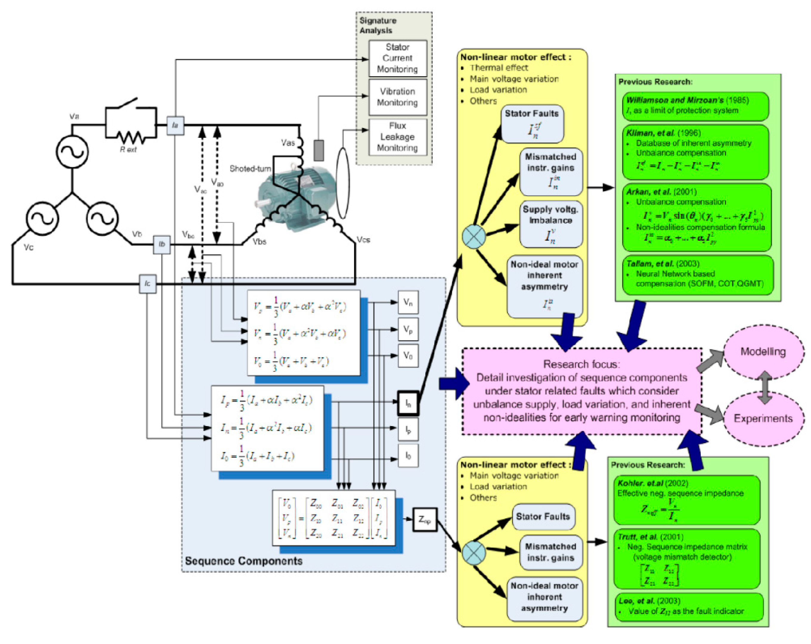
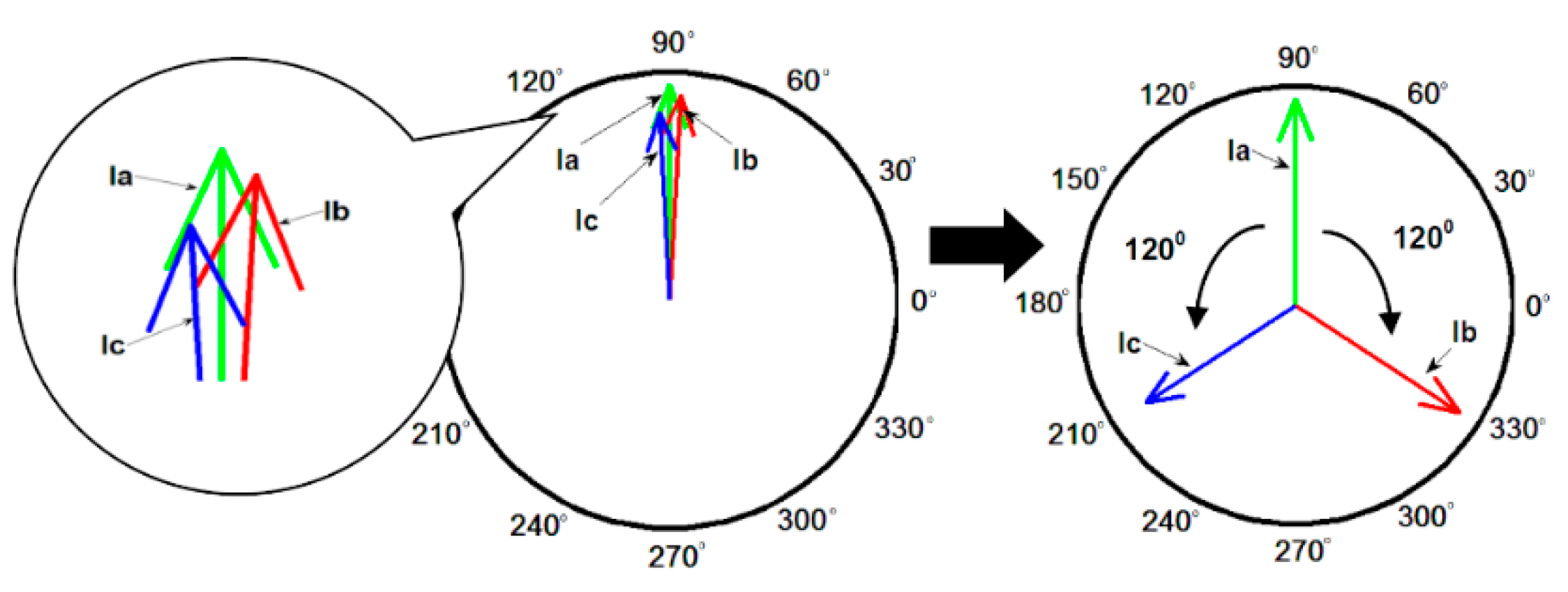
2. Negative Sequence Current Analysis

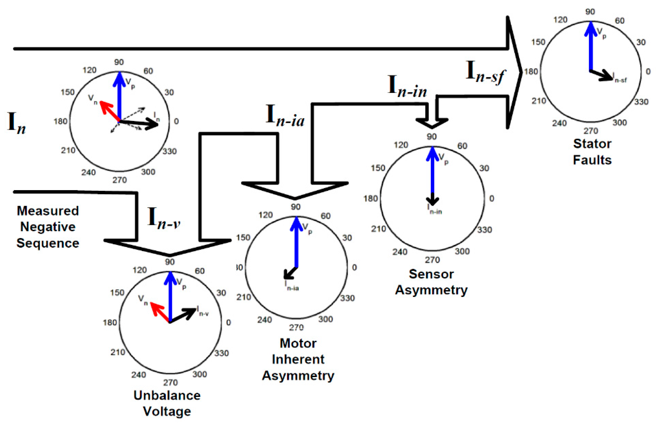
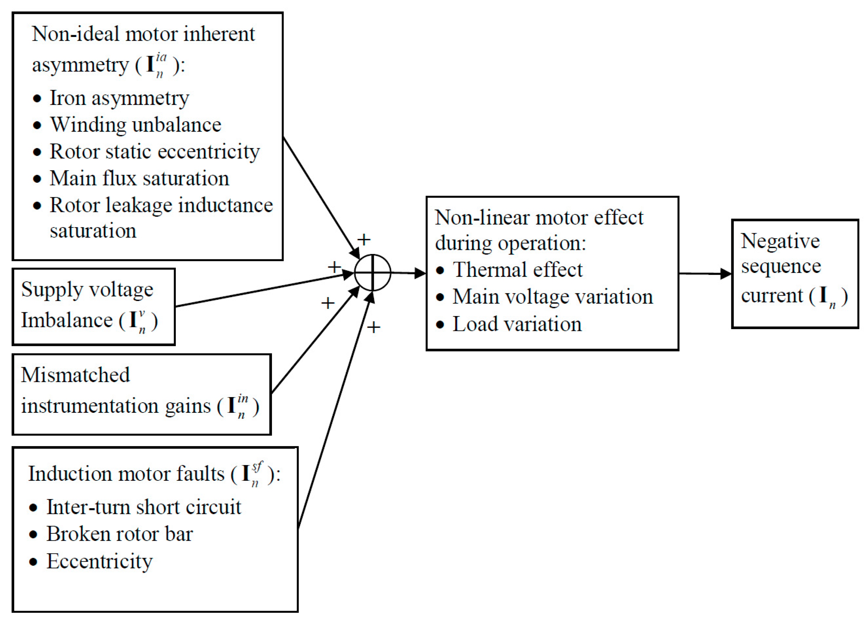
2.1. The Sources of Negative Sequence Current

An unbalanced three-phase set of current phasors, Ia, Ib and Ic can be represented as the superposition of three sets of balanced symmetrical component phasors: positive sequence Ip, negative sequence In and zero sequence I0.
Although balanced three-phase voltages applied to an ideal induction machine produces balanced currents with no negative sequence components, practical induction machines have some negative sequence current due to inherent asymmetries between the windings. In addition, even a perfectly balanced induction machine, when operating from an unbalanced supply, will have a negative sequence current which is equal to the negative sequence supply voltage divided by the negative sequence impedance, Zn, of the machine. In light of these practical limitations and using the summary of disturbances given in Figure 3, the sources of the negative sequence currents are discussed in detail below, which is critical for the phasor based compensation technique developed in the paper.

2.1.1. Measurement Asymmetry (In-in)

Given the negative sequence, components are associated with imbalances between the supply voltages/currents; even small differences in gain and phase between the voltage/current transducers in different phases can produce substantial errors in the results. Thus careful calibration of the transducers is crucial when seeking to accurately measure negative sequence currents.

2.1.2. Inherent Asymmetry (In-ia)

As indicated previously, due to the manufacturing limitations in machine production, negative sequence currents even occur in healthy motors as they contain inherent asymmetry. As summarized in Figure 3, inherent asymmetry may be due to iron asymmetry, stator winding unbalances and rotor static eccentricity.

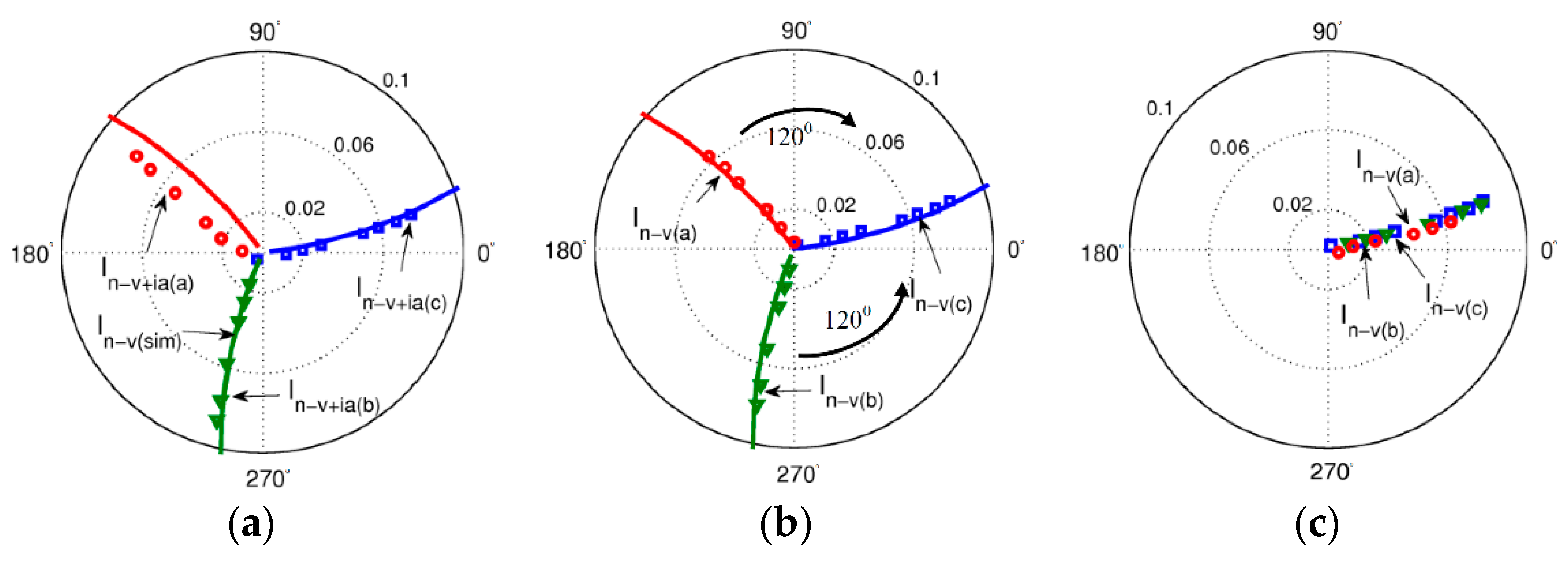
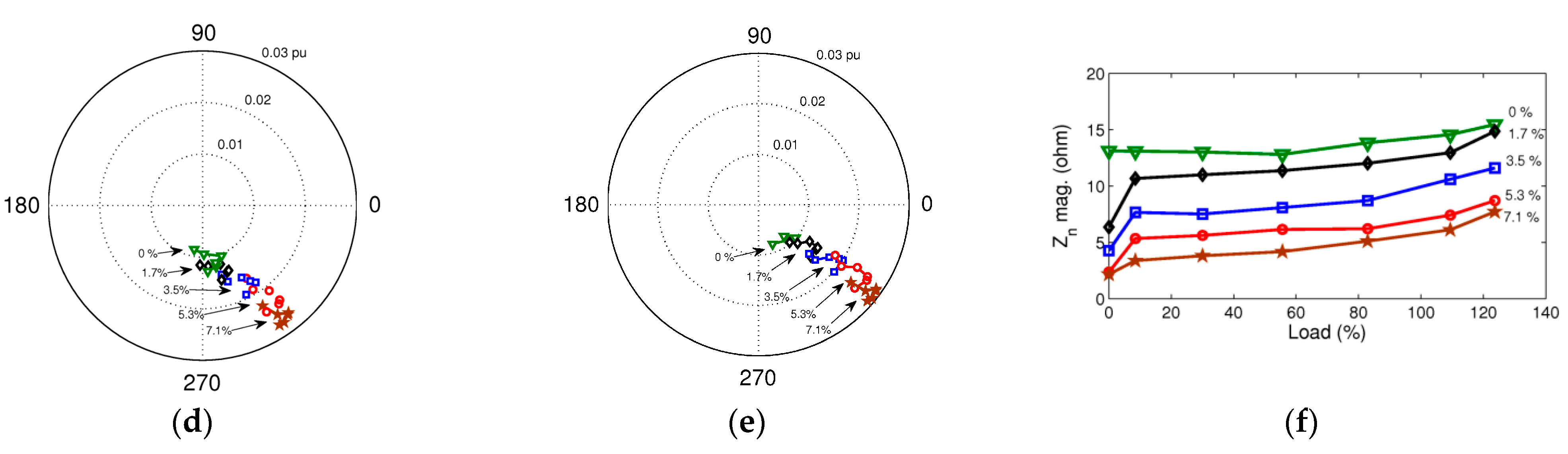
2.1.3. Voltage Unbalances (In-v)

All practical ac supplies have some degree of voltage imbalance. Compensation of the effect of supply voltage imbalance is important to separate this effect from the stator winding faults.

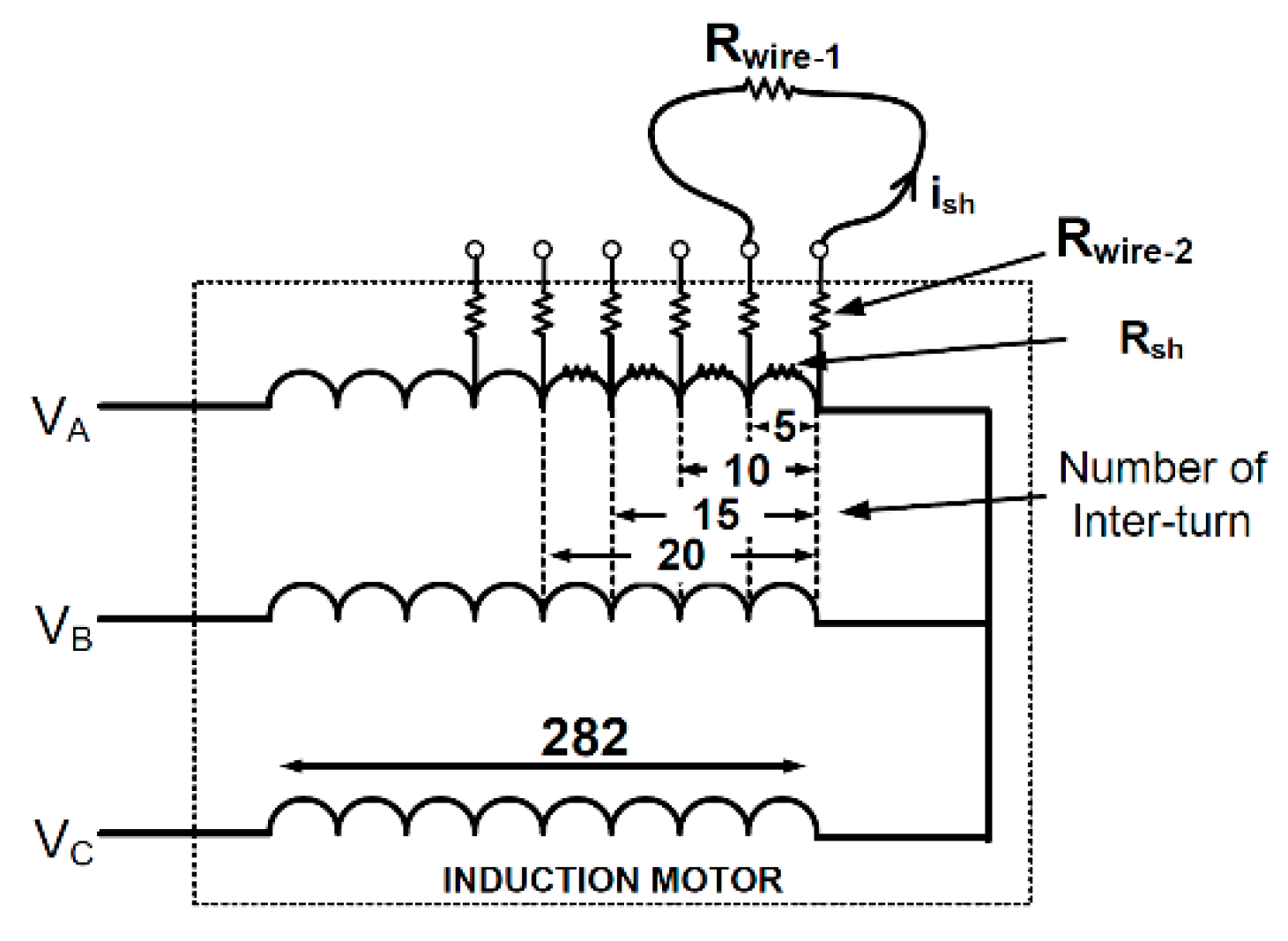
2.1.4. Induction Motor Faults (In-sf)

Negative sequence currents are produced by faults that cause asymmetries in the induction machine. Three major contributing faults are listed in Figure 3. However, the shorted turn fault is considered to be the most critical one since it generally develops faster than the eccentricity and/or broken rotor bar faults, and these other faults can also be effectively detected by alternative methods.

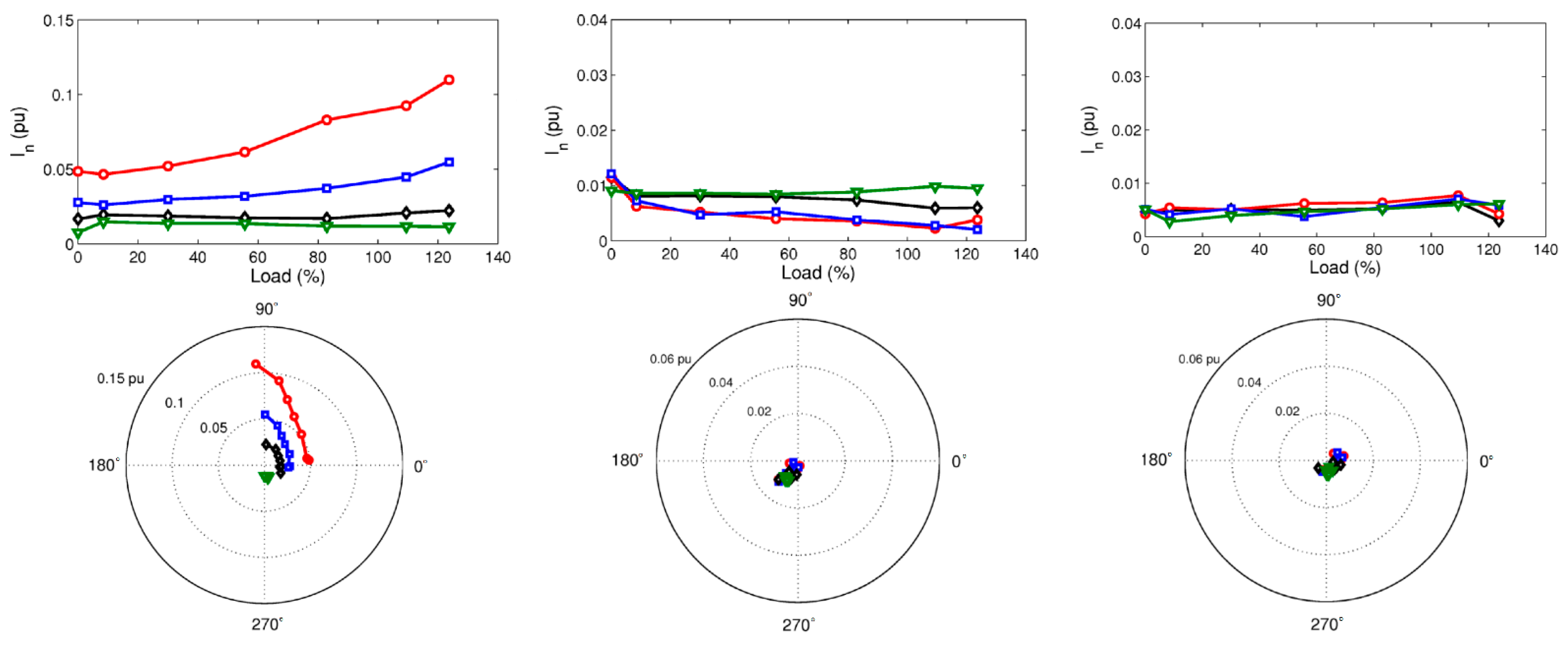
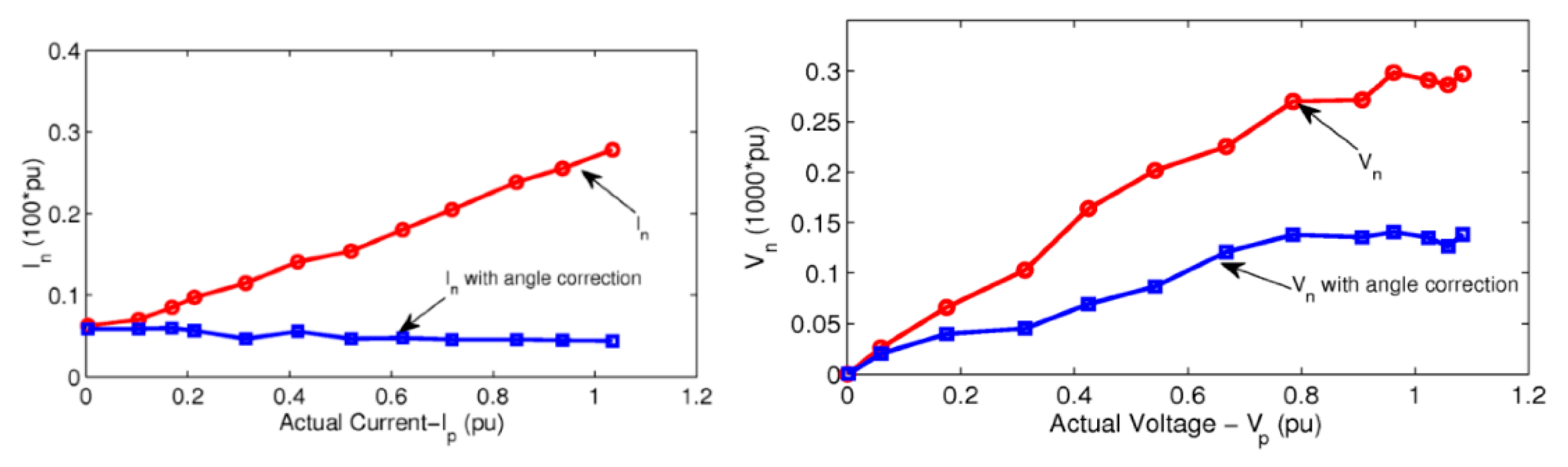
2.2. Principle of Phasor Compensation Technique

The negative sequence input current In of an induction machine can be expressed as the phasor sum of four separate negative sequence currents: motor faults In-sf, inherent asymmetry In-ia, measurement errors In-in and supply voltage unbalance In-v.
In = In-sf + In-ia + In-in + In-v
The above equation implies that negative sequence current components can exist even in healthy machines, and Figure 4 illustrate the implementation of the shorted turn fault extraction based on the same equation.
The negative sequence current component due to motor faults In-sf can be obtained from the measured negative sequence phasor In by subtracting the negative sequence current components due to voltage unbalance In-v, the motor inherent asymmetry In-ia and instrumentation asymmetry In-in. In addition, it can be assumed that the negative sequence current component due to shorted turn faults In-sf is proportional to the fault severity. It is also important to emphasize that the negative sequence current components can be sensitive to motor load variations and changes in motor temperature during operation.
As it is listed in Table 1, the negative sequence current can be used for shorted turn fault detection by utilizing the key fault indicators (given in the rightmost column) after compensating for the inherent asymmetry, voltage unbalance and load variations. In [6], the negative sequence impedance Zn due to voltage unbalance was assumed unaffected by load variations and hence was assumed independent of stator shorted-turn faults. Therefore, the negative sequence current for the voltage unbalance compensation can be obtained from the measured negative sequence voltage and a look-up table for Zn. The complex admittances method reported in [7] assumed that the healthy negative sequence current was a function of the positive and negative sequence supply voltages.
In [5], the healthy negative sequence impedance was estimated based on empirical formulas taking into account the effect of the voltage unbalance, load variation and inherent asymmetry. In [10,13], the negative sequence of the online sensor and inherent asymmetry model and measurement was demonstrated. These two papers show the negative sequence current due to stator faults which were free from the inherent asymmetry and uncalibrated sensor effects. Furthermore, in [8,12], a neural network was applied to estimate the healthy negative sequence current.
However, as observed from these earlier studies, the previous techniques consider only a limited number of cases without separating the negative sequence of current phasor components related to each type of disturbance. Therefore, in the following section, the principle of the phasor compensation technique will be explained graphically to demonstrate its effectiveness as a winding short-circuit fault detection method.

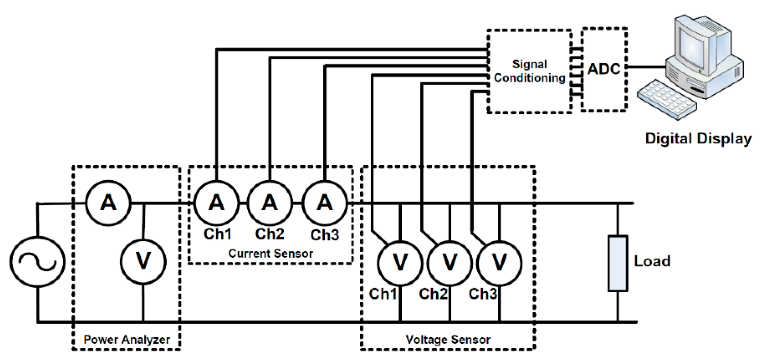
3. Simulation Study and Test Setup

To be able to understand the behavior of the induction machine under various fault levels, a Simulink model was developed. The parameters of the commercial test machine are given in Table 2. The simulation was based on a dynamic machine coupled circuit model [6], which allowed the simulation of unequal numbers of winding turns in each phase as well as inter-turn short circuits. This provided a comprehensive understanding of disturbances at different fault levels for the phasor-based compensation technique.
The stator winding of the test machine was specially re-wound to allow the introduction of various levels of shorted turn faults via external connections. In the test motor, 5, 10, 15 or 20 shorted turns can be applied in either one or two phases of the motor (see Figure 5). This corresponds to shorted turn faults of 1.7%, 3.5%, 5.3% and 7.1% per phase, respectively.
Note that the stator winding resistance for 5 turns was about 93 mΩ while for 20 turns, it was about 370 mΩ, which was estimated using the total measured resistance of the stator winding. As illustrated in Figure 5, the short-circuit current path had an additional stray resistance of Rwire1 + 2Rwire2, which was measured at about 125 mΩ. The machine model used in the simulation study included this stray resistance effect.
The measurement and the calibration system consisted of three voltage and three current transducers signal conditioning circuits, an eight-channel 8th order low-pass Butterworth analog filter and an eight-channel, 12-bit simultaneous sampling data acquisition card (see Figure 6). The current measurement resolution was 0.2 mA.
The analysis of instrumentation asymmetry will be discussed in the following section.

4. System Calibration and Disturbances

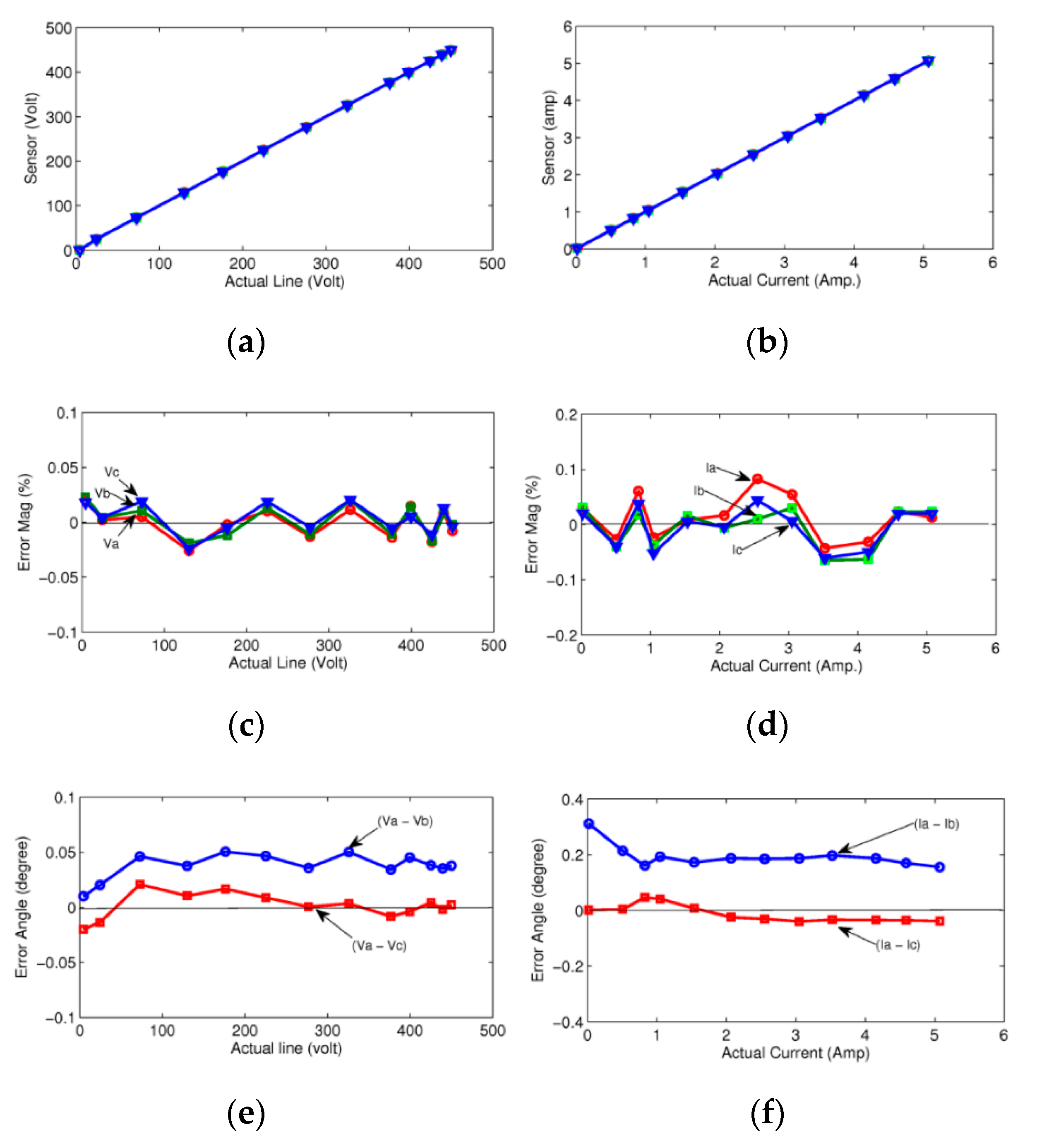
4.1. Sensor Calibration

During the calibration process, three current and three voltage sensors are configured to measure the same line current and the same phase voltage, as it is shown in Figure 6. A single-phase AC supply is also connected to a load via a precision power analyzer to provide the reference measurement. Table 3 indicate the calibration constants for each voltage and current sensor, and Figure 7 summarize the results of the calibration tests.
Note that before the calibration process, the maximum gain error of the voltage channels was about 1% and for the current channels was about 0.4%. After the calibration process, all the sensor measurements are compared with the values measured by the power analyzer to obtain residual magnitude errors, as given in Figure 7. The percentage error is expressed as the ratio of the error value and the full-scale reading output. The results show that the percentage error is less than 0.05% for the voltage magnitude measurement, and it is less than 0.1% for the current magnitude measurement. Such errors can be considered acceptable for the negative sequence component analysis.
The angle error analysis of the voltage and the current measurement is also given in Figure 7, which is defined as the relative angle difference between two channels, i.e., between the Va and Vb also the Va and Vc voltage channels. Note that the average angle error of the worst pair of currents (about 0.2°) is much lower than for the worst pair of voltages (about 0.05°). To understand the impact of such discrepancies, the measurement asymmetry needs to be analyzed. Since, in this test, the three current and voltage channels are supplied from the same source, the three phasors should ideally create a zero sequence component. Figure 8 show the three measured current phasors showing small residual magnitude errors and uncompensated phase errors. In order to find the negative sequence component phasors due to the measurement asymmetry, the two phasors (Ib and Ic) are each rotated 120°, as shown in the rightmost figure.
The magnitude of the negative sequence component due to measurement errors is given in Figure 9. This shows a 0.3% current component and 0.03% voltage component at rated current and voltage, respectively. This error can be reduced by subtracting a fixed value of angle offset between the channels of 0.2° for the current and 0.05° for the voltages. This angle offset correction reduces the negative sequence current error to lower than 0.1% of rated current and the negative sequence voltage error to 0.015% of rated voltage.

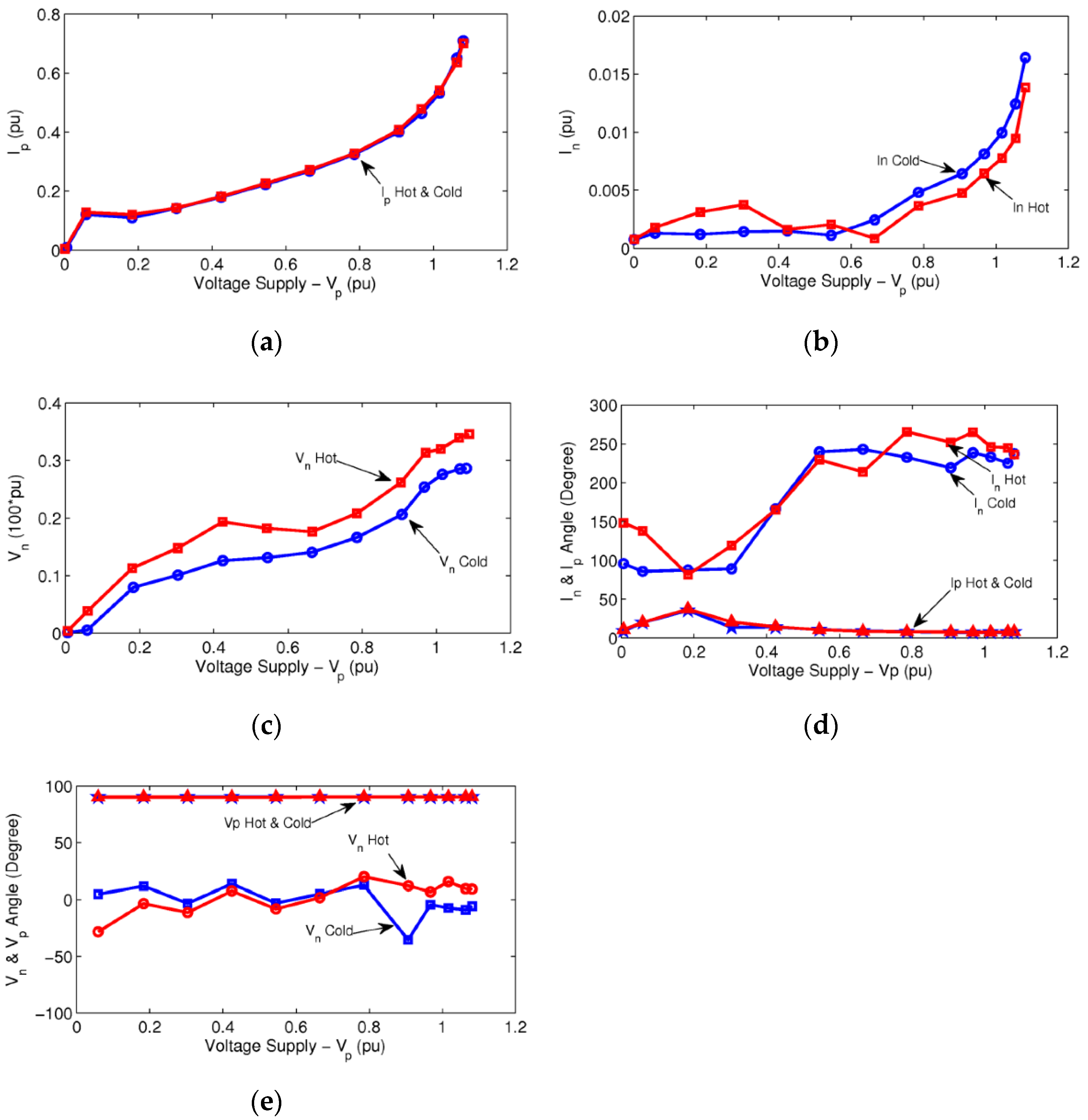
4.2. Motor Temperature

The effect of temperature is investigated and presented in Figure 10 using the measurement system and the induction motor under test. The no-load cold data test is performed within the first 15 min after the motor is started. The no-load hot data is obtained after running the motor in a generator mode at the full load condition for half an hour. Then, the generator is decoupled from the electrical load and tested and measured under no-load conditions. In both cases, the measurements are performed over a range of supply voltages.
Figure 10 show that there is little difference between the hot and cold positive sequence currents, but there are significant differences between the hot and cold negative sequence currents and voltages. At the rated voltage, the negative sequence current is about 1%, and the negative sequence voltage is about 0.2% which is much larger than the residual measurement errors discussed previously.
Figure 10b show that the negative sequence current increases rapidly for voltages above about 0.7 pu. This may be due to asymmetries in the saturation of the three phases.

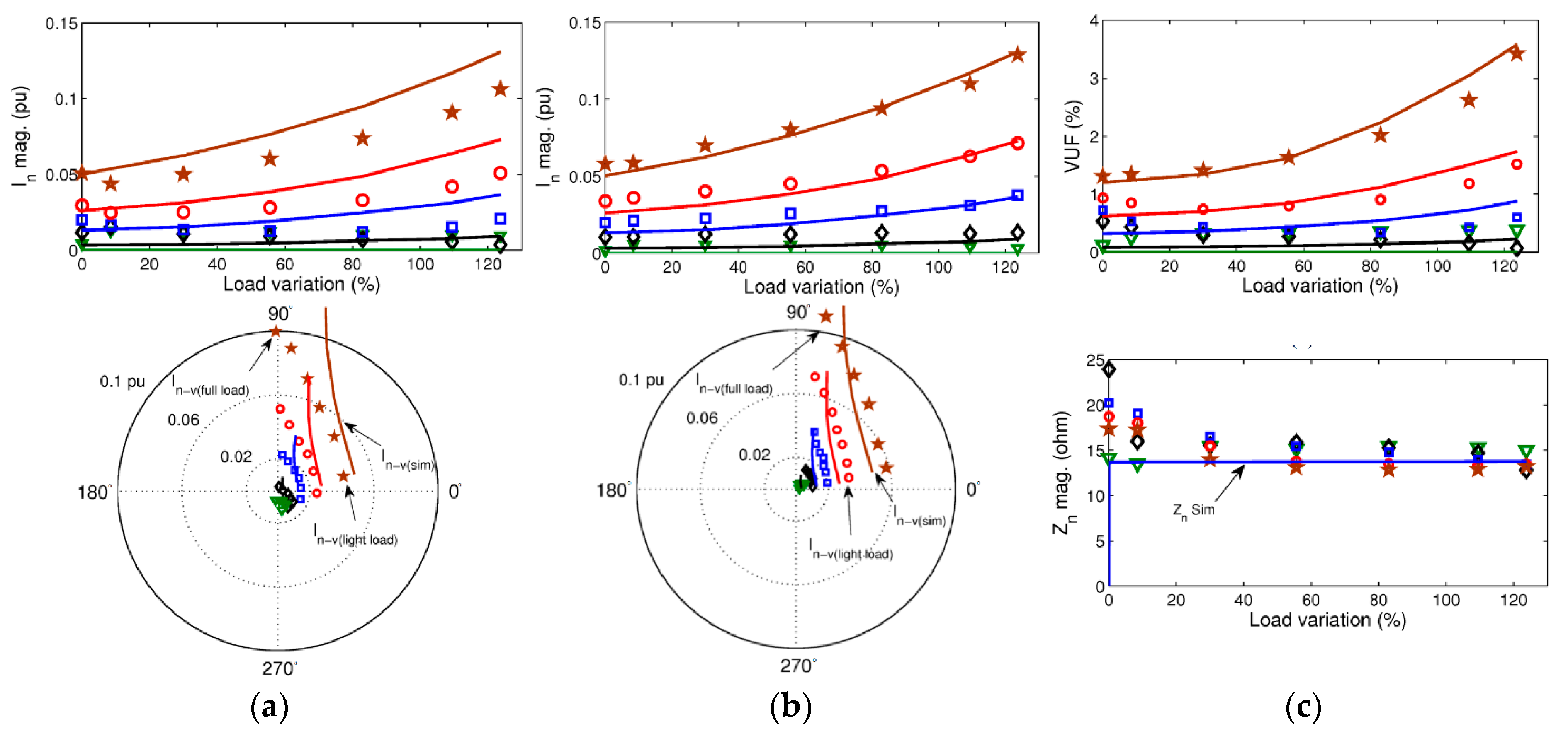
4.3. Voltage Unbalances

A supply voltage unbalance produces a negative sequence supply voltage which in turn produces a negative sequence current that is inversely proportional to the motor’s negative sequence impedance. The supply voltage unbalance is measured using the voltage unbalance factor (VUF), which is defined as the ratio between the negative sequence Vn and positive sequence Vp voltage magnitudes:
VUF = V n V p
A variable voltage unbalance is introduced experimentally in the computer simulations by adding a variable external resistor in series with one of the supply phases of the motor while operating under no-load conditions.
Figure 11 highlights the variations of the negative sequence current magnitudes as a function of voltage unbalance (left column) and current phasor plots of the negative sequence current (right column).
Figure 11a,b show the measured negative sequence current using uncalibrated (squares) and calibrated (circles) voltage and current sensors, as discussed at the beginning of this section, which all demonstrate the significance of calibration.
Figure 11a show an approximately linear relationship between the negative sequence current component and the voltage unbalance while the positive sequence current component (crosses) remains almost constant. Note that the percentage change in the negative sequence current is approximately four times the percentage change in the negative sequence current. The results are consistent with up to 5% voltage unbalance, which is an acceptable level in practice [17]. The effect of inherent asymmetry in the machine is also observed in the same figures, where extrapolating the measured voltage unbalance results in zero unbalance (see squares in Figure 11c) and does not result in zero negative sequence current.
The simulation results are shown as solid lines in Figure 11a,b. Although the simulation results in Figure 11a show significant discrepancies as a function of voltage unbalance, the simulation model predicts the current phasor trajectory accurately, as illustrated in Figure 11b (except for the un-modelled inherent asymmetry). The corrected experimental results (triangles) are also given after the experimentally determined inherent asymmetry currents (squares) are subtracted. The results are now consistent with zero negative sequence current at zero voltage unbalance.
Note that the above-described procedure was repeated in each of the three phases of the machine. Figure 12 show the simulation and the experimental results of this study before (Figure 12a) and after (Figure 12b) inherent asymmetry compensation, at which point the results become centered on the origin. Figure 12c illustrate the effect of 120° phase shifting in two of the phases, which demonstrates that the effect of voltage unbalance is similar in each phase. This is the basis for compensating the negative sequence current that is due to the supply voltage unbalance.
Figure 12 show the effect of voltage unbalance (using a resistor in series with one of the phase lines) on the negative sequence current under varying motor loads. The results are given before (Figure 12a) and after (Figure 12b) inherent asymmetry elimination, which shows that this substantially improves the correspondence between the simulated and test results.
The corresponding voltage unbalance factor and the negative sequence impedance are provided in Figure 12c. For a fixed supply unbalance resistor, increasing the load increases the voltage unbalance, which increases the negative sequence current and produces a phase angle change. The negative sequence impedances stay relatively constant.

5. Shorted Turn Motor Fault and Novel Phasor Compensation Technique

The effect of shorted turns was experimentally verified on the test machine using the tapped stator windings given in Figure 5 previously. This section explores the ability to detect such fault types and aims to estimate the severity of the fault.

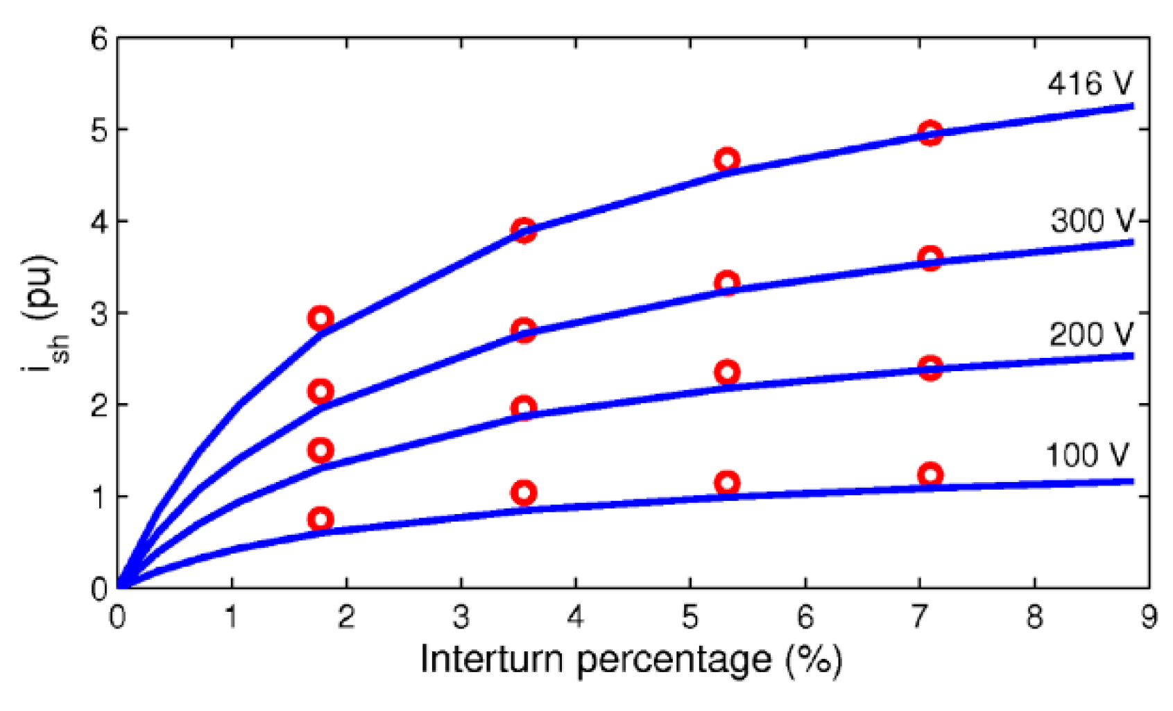
5.1. Effect of Shorted Turn Fault

Figure 13 show the variation of the fault current as a function of the shorted turn (inter-turn) percentage and the voltage supply level. If the resistance of the external wires used to tap the stator winding (Rwire in Figure 5) is zero, then the fault current should be ideally constant. However, with a finite external resistance, the fault current increases with a number of shorted turns and asymptotes towards the true short-circuit current value. This current is also proportional to supply voltage.
Since the fault currents produced by shorted turns are large, they can cause the rapid heating of the shorted windings and consecutive catastrophic failure. For example, at the rated voltage, a fault current of five times the rated current is produced with only 7% of the shorted turns. Therefore, fast fault detection is crucial for early inference.
Figure 14a show the negative and positive sequence current magnitudes as a function of the short-turn fault percentage. The figure indicates that the negative sequence current is almost proportional to the fault level with a 2% negative sequence current, which corresponds to the 7% shorted turns. It can be observed in the same results that the short-turn fault does not affect the positive sequence current significantly.
Figure 14b show the negative sequence current phasor trajectory corresponding to the shorted-turn faults on two phases only, which are tested one phase at a time. The results show a good correspondence between the simulation and the experimental results.
To be able to investigate the practical operating scenarios, the shorted turn faults are also studied under the combination of voltage unbalance and motor loading. The results before and after inherent asymmetry elimination are given in Figure 15. The figure shows that shorted turn faults increase the magnitude of the negative sequence current as well as varying its phasor trajectory under voltage unbalances.
Figure 15c,f show the percentage of voltage unbalance and the negative sequence impedance as a function of the motor load. As can be observed in the figures, the effect of the negative sequence current magnitude decreases slightly with increasing load (Figure 15a). This is caused by the negative sequence impedance (Figure 15f) that increases slightly with the load. However, the negative sequence voltage remains relatively constant, as illustrated in Figure 15c.

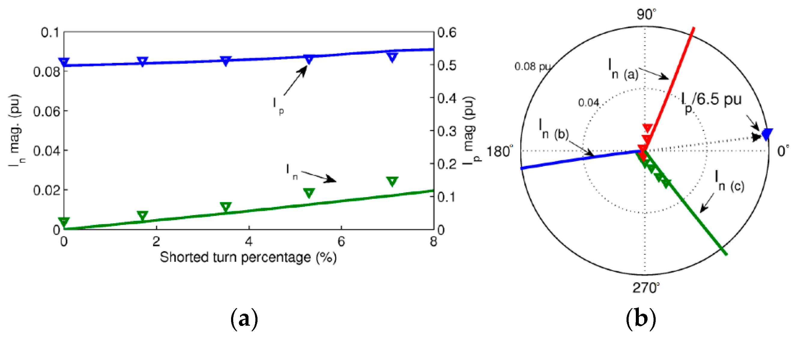
5.2. Shorted Turn Faults and Phasor Compensation

Figure 16 show the variation of the measured negative sequence current magnitude vs. the shorted-turn ratio (up to 7%) for different supply voltage unbalances (from 0.1% to 1.7%) under no-load conditions. Current trajectory plots are also given in the second row of the figure. The left column in the figure shows the measured results using the calibrated sensors; the middle column shows the results with compensation for supply voltage unbalance and the right column illustrates the results after both supply voltage imbalance and inherent asymmetry compensation.
As can be seen in the figure, with near-zero supply voltage unbalance (0.1%), the negative sequence current is almost proportional to the number of shorted turns. For example, a 7% shorted turn fault produces slightly more than 0.02 pu negative sequence current. However, in a healthy motor (zero shorted turns), 1% supply voltage unbalance can produce a comparable magnitude of negative sequence current, which indicates the necessity of compensation for the supply voltage unbalance.
In addition, the phasor plot in the left column of Figure 16 show that the phase angle of the negative sequence current component due to supply voltage unbalance (about +15°) is substantially different than that due to the shorted turn fault (about −45°). These phase angles are dependent on the negative sequence voltage phasor and the phase of the supply in which the shorted-turn fault is present.
The negative sequence current magnitude depends on the phasor summation of the negative sequence current components of the fault level and the supply voltage unbalance. Therefore, any compensation technique must be based on a phasor calculation rather than just considering the magnitudes.
The results of the negative sequence supply voltage compensation are given in the middle column of Figure 16, which utilized the calibration curve given previously. Note that when the sensitivity of the negative sequence current to the supply voltage unbalance is eliminated, this can magnify the influence of the shorted turn fault. In the phasor plot of Figure 16, the close correspondence between the results at 0.1% and 1.8% VUF is given.
The presence of inherent asymmetry, hence non-zero negative sequence current, in a healthy machine makes it difficult to identify the small level of shorted turn faults (less than 2% or five shorted turns in the test machine as it is given in the middle column of Figure 16).
The results given in the right column of Figure 17 show the compensation of both voltages unbalance and inherent asymmetry. Note that the compensation reduces the negative sequence current to near zero for healthy machines, which allows even small faults of greater than, say, 1% (3 shorted turns) to be distinguished. Moreover, an almost ideal linear relationship between the fault severity and the negative sequence current is obtained, which reduced the sensitivity to supply voltage unbalance further. The phasor plot shows the result for the healthy motor now lies at the origin. This means that the negative sequence current for the stator shorted turn faults is now fully compensated.
The left column in Figure 17 show the negative sequence current test results with a 1.7% shorted turn fault combined with a varying supply voltage unbalance (produced by external resistors of 0 Ω, 1 Ω, 2 Ω and 4 Ω) under various motor loads. The significant effects of loading and voltage unbalance are also visible from the change in angle of the negative sequence current components, i.e., from −43° to 95°. At the light motor loading, the negative sequence phase angle is shifted from −43° to +12°, primarily due to the shorted turn fault.
The measured negative sequence current variation under the load given in the middle of Figure 17 shows a significant reduction after compensation for the voltage unbalance. Note the order of magnitude changes in the scales of the vertical axis in Figure 17.
The right column in Figure 17 show the processed result after the inherent asymmetry elimination. Note also that the supply unbalance and the load variation are reduced even further. This demonstrates that the compensation technique can successfully eliminate the voltage unbalance and the inherent asymmetry under a wide range of motor load variations, which is performed to gain the true magnitude of the negative sequence current due to the early and accurate detection of the shorted turn fault.

6. Conclusions

The stator faults in three-phase induction motors are primarily associated with the windings and are found to be the most critical faults as they develop quickly, requiring fast online diagnostic methods. This paper utilized the negative sequence components of voltage and current for the identification of the asymmetrical behavior of motor windings under stator faults.
In order to understand the causes of negative sequence currents for the detection of shorted-turn faults in the line-operated induction machines, this paper provided a comprehensive study of the effects of the major asymmetrical disturbances on the negative sequence currents. These included the effects of measurement errors, motor temperature, inherent machine asymmetry and supply voltage unbalance, all under varying motor load conditions.
A novel phasor compensation technique was described for inherent asymmetry and supply voltage unbalance. This relies on performing tests to determine the inherent asymmetry and identify the effective negative sequence impedance at the operating voltage.
The simulation and experimental results demonstrated that the proposed approach allows the use of the negative sequence current to detect even at small shorted turn faults (2% for the test motor). In addition, the fault severity was estimated accurately using the compensating method for sensor errors, inherent asymmetry and voltage unbalance, which are all present in practical machines. The compensation of supply voltage unbalance under varying motor loads was also investigated in detail.
It can be concluded that further works can be conducted while the motor is operating under multiple faults, which may be based on an online model of the machine.

Author Contributions

Data curation, S.B.; Formal analysis, S.B.; Funding acquisition, N.E.; Investigation, S.B. and N.E.; Methodology, S.B. and N.E.; Software, S.B.; Supervision, N.E.; Validation, S.B.; Writing—review & editing, S.B. and N.E. All authors have read and agreed to the published version of the manuscript.

Funding

This research received no external funding.

Conflicts of Interest

The authors declare no conflict of interest.

References

  1. Haines, G.; Ertugrul, N. Application Sensorless State and Efficiency Estimation for Integrated Motor Systems. In Proceedings of the 13th IEEE International Conference on Power Electronics and Drive Systems (PEDS 2019), Toulouse, France, 9–12 July 2019. [Google Scholar]
  2. Bakhri, S. Detailed Investigation of Negative Sequence Current Compensation Technique for Stator Shorted Turn Fault Detection of Induction Motors. Ph.D. Thesis, University of Adelaide, Adelaide, Australia, 2013. [Google Scholar]
  3. Supangat, R.; Grieger, J.; Ertugrul, N.; Soong, W.L.; Gray, D.A.; Hansen, C. Investigation of static eccentricity fault frequencies using multiple sensors in induction motors and effects of loading. In Proceedings of the IECON 2006-32nd Annual Conference on IEEE Industrial Electronics, Paris, France, 6–10 November 2006; pp. 958–963. [Google Scholar]
  4. Supangat, R.; Ertugrul, N.; Soong, W.L.; Gray, D.A.; Hansen, C.; Grieger, J. Broken rotor bar fault detection in induction motors using starting current analysis. In Proceedings of the 2005 European Conference on Power Electronics and Applications, Dresden, Germany, 11–14 September 2005. [Google Scholar]
  5. Grubic, S.; Aller, J.M.; Lu, B.; Habetler, T.G. A survey on testing and monitoring methods for stator insulation systems of low-voltage induction machines focusing on turn insulation problems. IEEE Trans. Ind. Electron. 2008, 55, 4127–4136. [Google Scholar] [CrossRef] [Green Version]
  6. Bakhri, S.; Ertugrul, N.; Soong, W.L.; Arkan, M. Investigation of negative sequence components for stator shorted turn detection in induction motors. In Proceedings of the Australasian Universities Power Engineering Conference (AUPEC), Christchurch, New Zealand, 5–8 December 2010; pp. 1–6. [Google Scholar]
  7. Arkan, M.; Perovic, D.K.; Unsworth, P. Online stator fault diagnosis in induction motors. IEE Proc. Electr. Power Appl. 2001, 148, 537–547. [Google Scholar] [CrossRef]
  8. Kliman, G.B.; Premerlani, W.J.; Koegl, R.A.; Hoeweler, D. Sensitive, on-line turn-to-turn fault detection in AC motors. Electr. Mach. Power Syst. 2000, 28, 915–927. [Google Scholar]
  9. Tallam, R.M.; Habetler, T.G.; Harley, R.G. Transient model for induction machines with stator winding turn faults. IEEE Trans. Ind. Appl. 2002, 38, 632–637. [Google Scholar] [CrossRef]
  10. Tallam, R.M.; Habetler, T.G.; Harley, R.G. Experimental testing of a neural-network-based turn-fault detection scheme for induction machines under accelerated insulation failure conditions. In Proceedings of the 4th IEEE International Symposium on Diagnostics for Electric Machines, Power Electronics and Drives 2003 (SDEMPED 2003), Atlanta, GA, USA, 24–26 August 2003; IEEE: Piscataway, NJ, USA, 2003; pp. 58–62. [Google Scholar]
  11. Asfani, D.A.; Morel, J.; Purnomo, M.H.; Hiyama, T. Simulation and detection of temporary short circuit in induction motor windings using negative sequence current. In Proceedings of the 2011 International Conference on Advanced Power System Automation and Protection (APAP), Beijing, China, 16–20 October 2011; pp. 2304–2308. [Google Scholar]
  12. Bouzid, M.B.K.; Champenois, G. New Expressions of Symmetrical Components of the Induction Motor Under Stator Faults. IEEE Trans. Ind. Electron. 2013, 60, 4093–4102. [Google Scholar] [CrossRef]
  13. Mengoni, M.; Zarri, L.; Gritli, Y.; Tani, A.; Filippetti, F.; Lee, S.B. Online Detection of High-Resistance Connections with Negative-Sequence Regulators in Three-Phase Induction Motor Drives. IEEE Trans. Ind. Appl. 2015, 51, 1579–1586. [Google Scholar] [CrossRef]
  14. Lashkari, N.; Poshtan, J. Detection and discrimination of stator interturn fault and unbalanced supply voltage fault in induction motor using neural network. In Proceedings of the 6th 2015 Power Electronics, Drives Systems & Technologies Conference (PEDSTC), Tehran, Iran, 3–4 February 2015; IEEE: Piscataway, NJ, USA, 2015; pp. 275–280. [Google Scholar]
  15. Bouzid, M.; Champenois, G. Experimental compensation of the negative sequence current for accurate stator fault detection in induction motors. In Proceedings of the Industrial Electronics Society, IECON 2013-39th Annual Conference of the IEEE, Vienna, Austria, 10–13 November 2013; IEEE: Piscataway, NJ, USA, 2013; pp. 2804–2809. [Google Scholar]
  16. Kohler, J.L.; Sottile, J.; Trutt, F.C. Condition monitoring of stator windings in induction motors: Part I-Experimental investigation of the effective negative-sequence impedance detector. IEEE Trans. Ind. Appl. 2002, 38, 1447–1453. [Google Scholar] [CrossRef]
  17. Lee, S.B.; Tallam, R.M.; Habetler, T.G. A robust, on-line turn-fault detection technique for induction machines based on monitoring the sequence component impedance matrix. IEEE Trans. Power Electron. 2003, 18, 865–872. [Google Scholar]
Figure 1. The breakdown of global motor usage by size (a) [1], and distribution of common faults of electric motors (b) according to EPRI survey results [2].
Energies 15 03100 g001
Figure 2. The summary of previous studies and the research opportunities for negative sequence components.
Energies 15 03100 g002
Figure 3. Main sources of negative sequence currents in induction motors.
Energies 15 03100 g003
Figure 4. The compensation techniques using phasor calculations, where both the magnitude and the phase of the negative sequence current are illustrated to separate the stator faults.
Energies 15 03100 g004
Figure 5. The modified stator winding configuration of the test motor and the external connection circuit used to introduce shorted turn faults (the motor windings have 282 series turns per phase).
Energies 15 03100 g005
Figure 6. The measurement system used for the voltage and current sensor calibration.
Energies 15 03100 g006
Figure 7. The measured and processed calibration characteristics: the calibrated values of voltage (a) and current (b), the residual magnitude errors in three voltage (c) and current sensors (d) and the relative angle errors for the three voltage (e) and current sensors (f).
Energies 15 03100 g007
Figure 8. Illustration of the angle displacement for the sequence component analysis.
Energies 15 03100 g008
Figure 9. The magnitude of negative sequence components before and after offset angle correction, (left) for current and (right) for voltage.
Energies 15 03100 g009
Figure 10. Hot and cold motor measurements: (a) magnitude of the stator positive sequence current Ip, (b) magnitude of the stator negative sequence current In, (c) magnitude of the negative sequence voltage Vn, (d) the angle of In and Ip, (e) the angle of Vn and Vp where the reference angle Vp is 90°.
Energies 15 03100 g010
Figure 11. Three-phase phasor representation of the negative sequence current under a supply voltage unbalance: before (a) and after (b) inherent asymmetry compensation, and after 120° shift of two phases (c). The simulation results are shown by solid lines. The experimental results are indicated by symbols.
Energies 15 03100 g011
Figure 12. The experimental (symbols) and the simulated (solid lines) results of the current and voltage unbalance as a function of the load with a series resistor in one of the phases. The magnitude (top) and phasor trajectories (bottom) are also given before (a) and after (b) inherent asymmetry elimination, and the voltage unbalance factor (top) and negative sequence impedance (bottom) (c). The values of the external resistors were 0.25 Ω (triangle), 0.5 Ω (diamond), 1 Ω (square), 2 Ω (circle) and 4 Ω (star).
Energies 15 03100 g012
Figure 13. The fault current in the shorted-turns vs. the fraction of shorted-turns with different supply voltages. Simulation results (lines) and experimental results (circles).
Energies 15 03100 g013
Figure 14. The experimental (symbols) and simulated (solid lines) results at varying shorted turn fault levels of 1.7%, 3.1%, 5.3% and 7.1%: the magnitudes of the positive and the negative sequence currents (a) and the negative sequence phasor trajectory for faults in two phases (b).
Energies 15 03100 g014
Figure 15. The test results at various shorted turn fault levels of 0% (triangle), 1.7% (diamond), 3.5% (square), 5.3% (circle) and 7.1% (star), before inherent asymmetry elimination of the magnitude of In (a), phasor diagram of In (d), after inherent asymmetry elimination of the magnitude of In (b), phasor diagram of In (e), and the corresponding voltage unbalance factors and (c) the negative sequence impedances (f).
Energies 15 03100 g015aEnergies 15 03100 g015b
Figure 16. The test results (magnitude and phasor plots) of the negative sequence current magnitude as a function of shorted turn fault severity (up to 7.1%) with voltage unbalance factors between 0.1% to 1.7%: measured results (left column) after voltage unbalance compensation (middle column) and after both voltage unbalance and inherent asymmetry compensation (right column).
Energies 15 03100 g016
Figure 17. The test results (magnitude and phasor plots) of the negative sequence current at 1.7% shorted turn fault severity vs. motor load with various voltage unbalance factors: measured results (left column) after voltage unbalance compensation (middle column) and after voltage unbalance and inherent asymmetry compensation (right column).
Energies 15 03100 g017
Table 1. Features of Negative Sequence Current Compensation Techniques Reported in the Literature.
ReferencesInherent AsymmetryVoltage UnbalanceLoad VariationShorted Turn Fault
[6]Compensation of non-linearity (including inherent asymmetry) using look-up table Negative sequence impedance Zn of motor (assumed independent load variation and turn faults)Unaffected by load variation Negative sequence current
In-sf
[5]Minimization of thermal effect by eliminating the current phase
Isn = (Vn sin θn)/Xhn
Semi-empirical quadratic function of healthy reactance (Xhn) X h n 1 = γ 0 + γ 1 V n + γ 2 sin 2 ϕ n + γ 3 cos 2 ϕ n + γ 4 I p x + γ 5 I p y 2 Semi-empirical quadratic function of stator current under load variations
I m n l v = α 0 + α 1 I p x + α 2 I p x 2 + α 3 I p y + α 4 I p y 2
Negative sequence current
I n - s f = I n I s n I m n l v
[7]Complex constants (k) In = k1Vp + k2VnComplex constants (k)
In = k1Vp + k2Vn
k1 and k2 are load dependent Negative sequence current In-sf
[10,13]Calculated from two current sensors based-method Ia and Ib; Negative sequence due to uncalibrated sensor is also considered
I n - i a = 1 3 ( 1 a ) ( I a a I b )
Voltage unbalance supply is not consideredTested under no-load, half load and full loadNegative sequence current In-sf
[8,12]Neural networkNeural networkNeural networkNegative sequence current In-sf
[14]Need to be perfectly balanced Need a balanced voltage supply Load is not affectedEffective negative sequence impedance: Zn-eff = Vn/In
[15]Independent of inherent asymmetryIndependent of voltage unbalanceCalculation under speed variationNegative sequence impedance
matrix Znp
[11]Proportional integral (PI) controller. The PI negative sequence regulator is not intended for monitoringPI controllerPI controllerNot available
Notes: X: Magnitude of reactance; ϕ: Phase angle; I: Magnitude of current; h: Operator for symmetrical components; V: Magnitude of voltage; x, y: Real and imaginary parts of a phasor; s, r: Subscripts for the quantities of stator and rotor; 0, p, n: Subscripts for zero, positive and negative sequence components; f: Supply frequency; m, s, l, v: Subscripts denoting motor, supply, load and voltage.
Table 2. Equivalent Circuit Parameters of the Motor under Test.
Rated output power2.2 kWReferred rotor resistance4.65 ohm
Rated frequency50 HzStator leakage inductance14.8 mH
Line voltage415 VReferred rotor leakage inductance14.8 mH
Rated stator current4.9 ARotor inertia0.05 kg m2
Number of series turns/phase282 turnsMagnetizing inductance312 mH
No. of poles4 Rated power factor0.8 lag
Stator phase winding resistance5.22 ohmRated speed1415 rpm
Table 3. The Calibration of Voltage and Current Channels.
ChannelVoltageCurrent
Ay = 2.4 × 10⁻⁵ + 8.84 × 10⁻³xy = −4.93 × 10⁻⁵ + 0.489x
By = 1.1 × 10⁻³ + 8.88 × 10⁻³xy = −8.19 × 10⁻⁵ + 0.490x
Cy = 4.6 × 10⁻⁴ + 8.93 × 10⁻³xy = −1.07 × 10⁻⁴ + 0.488x
Publisher’s Note: MDPI stays neutral with regard to jurisdictional claims in published maps and institutional affiliations.

