Article

Conjugate Heat Transfer Analysis of the Aero-Thermal Impact of Different Feeding Geometries for Internal Cooling in Lifetime Extension Processes for Heavy-Duty Gas Turbines

1
Politecnico di Torino, Dipartimento Energia DENERG, Corso Duca degli Abruzzi, 24, 10129 Torino, Italy
2
EthosEnergy Italia S.p.A., Corso Romania, 661, 10156 Torino, Italy
*
Author to whom correspondence should be addressed.
Energies 2022, 15(9), 3022; https://doi.org/10.3390/en15093022
Submission received: 6 March 2022 / Revised: 13 April 2022 / Accepted: 18 April 2022 / Published: 20 April 2022

Abstract

:
Regulations from the European Union move towards a constant reduction of pollutant emissions to match the single-digit goal by 2050. Original equipment manufacturers propose newly designed components for the lifetime extension ofgGas turbines that both reduce emissions and allow for increasing thermodynamic performance by redesigning turbine cooling geometries and optimizing secondary air systems. The optimal design of internal cooling geometries allows for reducing both blade metal temperature and coolant mass-flow rates. In the present study, four different geometries of the region upstream from the blade’s internal cooling channels are investigated by using computational fluid dynamics with a conjugate heat transfer approach. The baseline configuration is compared to solutions that include turbulators, vanes, and a diffuser-like shapes. The impact of each solution on the blade metal temperature is thoroughly analysed. The diffuser-like solution allows for a more uniform distribution of the coolant and may reduce the metal temperature by 30% in the central part of the blade. There are also regions where the metal temperature increases up to 15%, thus requiring a specific thermal fatigue analysis. Eventually, the non-negligible impact of the coolant flow purged in the tip clearance region on the generation of the tip leakage vortex is described.

1. Introduction

The quest for ever-rising performance in turbomachinery Bontempo and Manna [1] has boosted turbine inlet temperature (TIT) values far beyond the allowed material temperature of hot gas path components. It has been calculated by Montomoli et al. [2] that an increase of 10K in a high-pressure turbine (HPT) vane metal’s temperature could reduce its residual lifetime by a factor of 37 % . To ensure components reliability under extreme working conditions, HPT vanes and blades rely extensively on cooling methods that reduce the heat load by lowering the metal temperature. A blade life sensitivity study conducted by Haubert et al. [3], ranked the coolant mass-flow rate and the TIT among the five most relevant parameters determining the failure of the component. Similar conclusions have been reached by Kim et al. [4], who adopted a probabilistic approach to evaluate the sensitivity of several operating parameters on the prediction of blade temperature and stresses. It was found that the performance of a blade featuring external film cooling was particularly sensitive to the ratio of coolant source pressure to the hot gas path static pressure.
Usually, coolant air is drawn off the last stage of the compressor and driven to cooling channels through a circuit of ducts usually referred to as secondary air systems (SAS). State-of-the-art components feature intricate cooling passages, whose geometry aims at both maximizing the available area and promoting turbulence, thus increasing the heat transfer coefficient. External cooling methods complete the overview, creating a protective film by forcing air ejection throughout holes manufactured on the hot gas path surfaces. Horlock [5] demonstrates that the spillage of compressed air generates a penalty on the overall efficiency and urges researchers to devise more sophisticated cooling techniques that are able to fully exploit the cooling power of the extracted air. As the latter passes through the SAS, it undergoes pressure losses and an increase in temperature, thus negatively affecting the overall cooling performance. Therefore, the modification of the cooling systems should include the redesign of the secondary passages to maximize the overall effect by granting optimal cooling channels inlet conditions and by reducing the end-wall heat load.
Despite the relevance of this topic, only a few studies have been dedicated to the analysis of the detrimental effect of non-optimized solutions on the distribution of the coolant flows in the internal cooling channels. Moreover, most of the studies relate to channel and turbulator shapes. Among the most relevant studies, Takahashi et al. [6] performed three-dimensional simulations of the internal and external flow of a blade with multiple cooling holes under different cooling air conditions, observing that the reduction of coolant capacity resulted in lower temperature difference between inside and outside of the blade. Sierra Espinosa et al. [7] investigated the influence of the cooling flow rate on the temperature profile of the high-pressure blade of an industrial gas turbine with single-pass radial cooling channels. Their experimental and numerical analyses demonstrate poor cooling performance at reduced coolant flow rate. Both Alizadeh et al. [8] and Rezazadeh Reyhani et al. [9] show sensitivity analyses of turbine blade temperature to the pressure drop and the temperature rise in the SAS, thus demonstrating that these parameters have a serious impact on both blade average and maximum temperature.
Williams et al. [10] conducted experiments on a turbine airfoil featuring both internal cooling by flow impingement and external cooling provided by a single row of round holes positioned on the suction side. The adiabatic and overall cooling effectiveness are evaluated under different coolant-to-main flow momentum ratios, showing that while the former tends to decrease with an increasing momentum ratio, due to coolant jet separation the latter undergoes a stable increase, thanks to the augmented internal cooling effects. The same trends are reported by Nathan et al. [11], who investigated a turbine airfoil with flow impingement for the internal cooling and a showerhead configuration of five rows of holes for the external cooling. In this case, the adiabatic effectiveness increases up to a maximum value with increasing momentum ratio. That outcome is caused by the fact that coolant jets always present a detached conditions, at least for the tested range of momentum ratios. Conversely, the overall cooling effectiveness is found to increase steadily with the momentum ratio.
Garg and Gaugler [12] specifically investigates the effects of coolant flow rate and inlet temperature on film cooling performance of a turbine blade, using a three-dimensional CFD model. They conclude that the adiabatic effectiveness is generally lower for higher coolant temperatures, and that this has to be attributed to the non-linearity of air compressibility. The effect of coolant flow rate, instead, was observed to change in different regions of the blade. On the suction side, the effectiveness passed through a minimum as the flow rate increases; on the pressure side, the effectiveness decreases with increased coolant flow rate. The sensitivity of cooling effectiveness under different coolant inlet temperatures was also the object of the study of Prapamonthon et al. [13]. They find that an increase of 8% in the coolant inlet temperatures produces a reduction in the overall cooling effectiveness from 0.665 to 0.616, corresponding to an increase in the average vane temperature of 18K. In a research work presented by Amaral et al. [14] and Verstraete et al. [15], the impact of the presence of internal cooling channels on the von Mises stresses of the HPT blade end-wall is initially quantified, then the channels design is optimized by also including the feeding passages through the blade root.
Some of the aforementioned studies [6,7,8,9] rely on three-dimensional simulations of both the hot and the cold flow path, together with the heat conduction in the solid blade domain. This rather time-consuming numerical procedure is necessary to accurately reproduce the complex flow and heat transfer mechanisms involved in turbine blades applications. Despite the high accuracy that the studies reported, the air flow inlet conditions are set by considering SAS analysis and little or no attention is dedicated to the sector of the SAS that delivers the coolant across the blade root to the cooling channels. In real applications, though, this part of the cooling system may play a key role in determining the cooling performance. In fact, the work by Puttock-Brown and Rose [16] describes the formation and evolution of vortices in the plenum-like rotating cavities that could affect the distribution of coolant among the internal cooling passages.
In the present work, conjugate heat transfer (CHT) simulations are performed using the Simcenter STAR-CCM+ solver in order to investigate into the effect of the geometrical features of the SAS in the blade root region over the performance of the cooling system of a HPT blade. The design case is compared with three newly-proposed concepts, featuring streamlined shapes and flow perturbators. The impact of these designs over the coolant distribution in the blade profile radial channels is evaluated by comparing the absolute values of both the delivered mass-flow rate and temperatures and their uniformity among channels. The effect of coolant distribution over the blade temperature is also quantified, addressing the origin of such differences. Eventually, the impact of different SAS configurations on the aero-thermal characteristics of the blade tip region is investigated, thus demonstrating that a variation up to ± 40 % can be found depending on the coolant mass-flow distribution through the internal cooling holes.

2. Presentation of the Geometry under Study

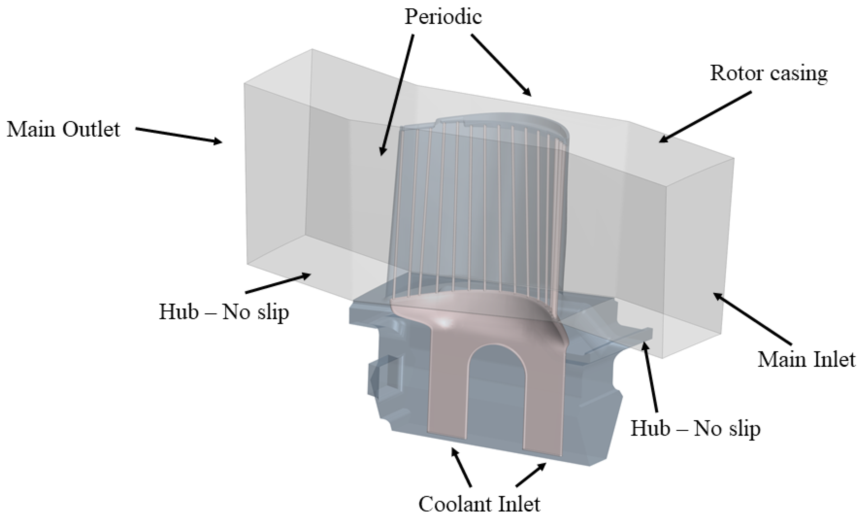
The case study is an industrial high-pressure rotor blade, whose full geometry is reported in Figure 1. Inter-stage bleeding is not activated under the normal operation of the machine, thus the coolant air is spilled at the compressor delivery section. The coolant is then split into two flows: the first one is devoted to vane cooling, whereas the second is delivered to the rotor section. The first rotor blade features 15 radial cooling channels which run through the blade. The first three channels close to the blade leading edge (LE) are characterized by a non-dimensional diameter of 0.027 with respect to the axial chord of the blade at mid-span, which is used as reference length, while the remaining twelve channels are smaller (0.017). In the following analysis, the channels will be numbered from 1 to 15, starting from the LE of the blade. The coolant running through the blade profile is delivered through the two radial channels that discharge the flow in a plenum before it is fed to the blade section. The total non-dimensional height of the radial channels and the plenum is approximately 1, the height of the blade is 1.17 times the axial chord, and the non-dimensional tip clearance is 0.02. In this article, the main objective is the investigation of the effect that the coolant supply channels retain on the conjugate heat transfer and the mass-flow rate distribution over the radial channels and the squealer tip of the blade.
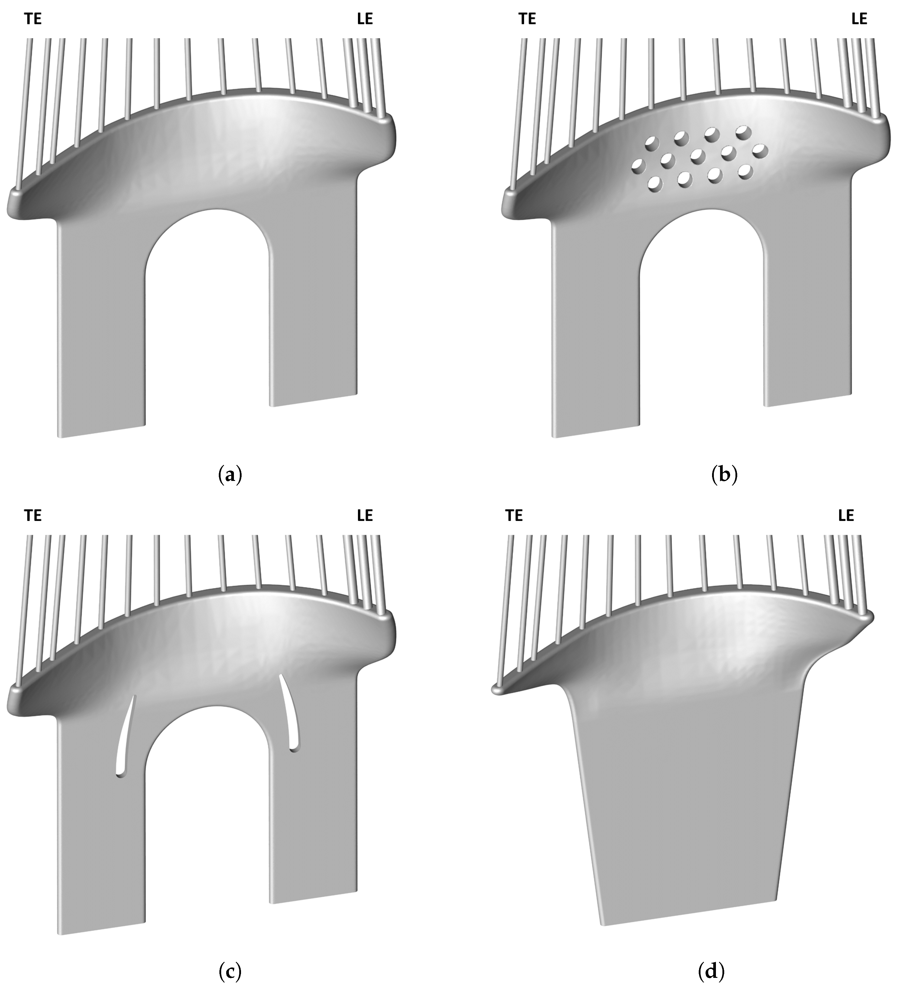
In this framework, three modified geometries of the plenum shape have been investigated into to detect the most promising design tendency, as shown in Figure 2. Figure 2a depicts the current design geometry, which already guarantees the correct levels of in-service metal temperature and serves as reference case for the evaluation of the performance of the other designs. Figure 2b shows cylindrical inserts in the original plenum shape which are expected to force the flow to enter uniformly into the central channels. Figure 2c shows the same plenum as for the reference case with two aerodynamic inserts to guide the flow towards the central region of the plenum. Finally, Figure 2d shows a diffuser-like shape for the plenum that is meant to help the flow expansion towards the radial channels.

3. Numerical Approach

The numerical campaign has been performed through the commercial solver Simcenter STAR-CCM+ by Siemens. Steady state simulations have been run, enforcing 2nd order discretization for convective terms. The hybrid Gauss–Green least square method was adopted for the discretization of the gradients. Turbulence is modelled using the k- ω SST model by Menter et al. Menter [17].
The numerical domain of the present investigation is reported in Figure 1. In order to impose a representative flow profile at the main inlet of the rotor blade, streamlines analysis have been performed in AxStream
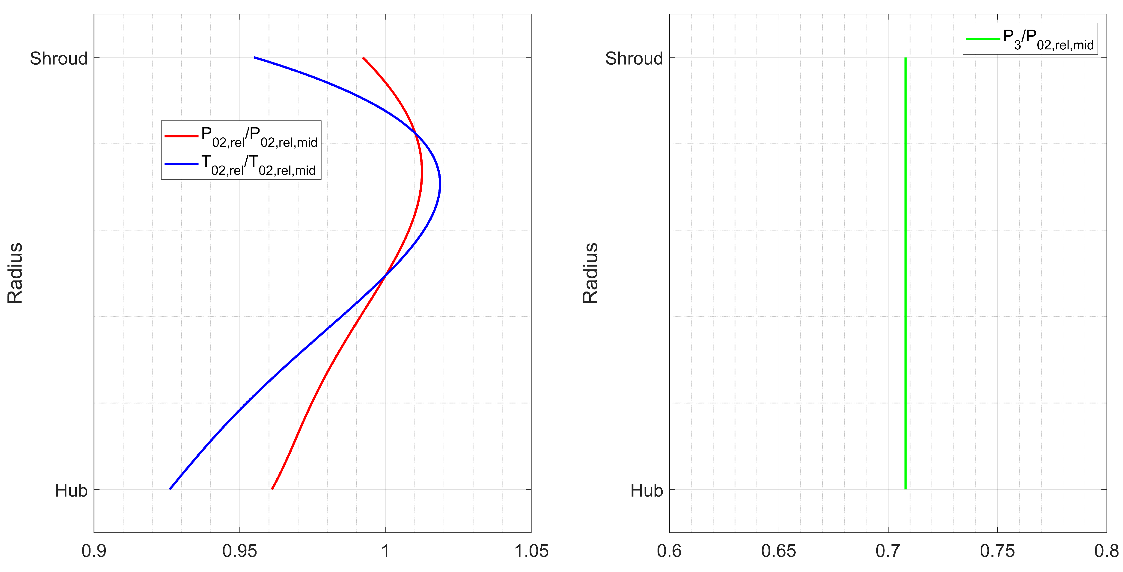
® by Softinway Incorporated on the full gas turbine. Relative pressure, relative temperature, and yaw angle radial distributions were then fitted using a polynomial law and imposed as boundary conditions for the rotor blade. Concerning the rotor outlet, an average static pressure has been applied. More details about the main-flow boundary conditions can be found in Figure 3. The inlet relative total pressure and temperature are normalized to the corresponding mid-span values. The outlet static pressure is normalized with respect to the inlet relative total pressure at the mid-span. As far as the coolant is concerned, uniform relative total pressure and temperature have been imposed at its inlet sections. These were obtained with the internal simulations of the secondary air systems of the turbine, as reported in Baratta et al. [18]. For the present investigation, the relative total pressure at the coolant inlet section is set to P 0 c o o l a n t 1.27 P 02 , r e l , m i d , while the relative total temperature is set to T 0 , c o o l a n t 0.4 T 02 , r e l , m i d . Regarding the solid, the thermal conductivity and the specific heat have been set equal to k = 16.74 W/(m·K) and c = 508 J/(kg·K), which are characteristic of the IN-738 at 500 ∘C. No thermal barrier coating or surface treatment is present in the investigated configuration.
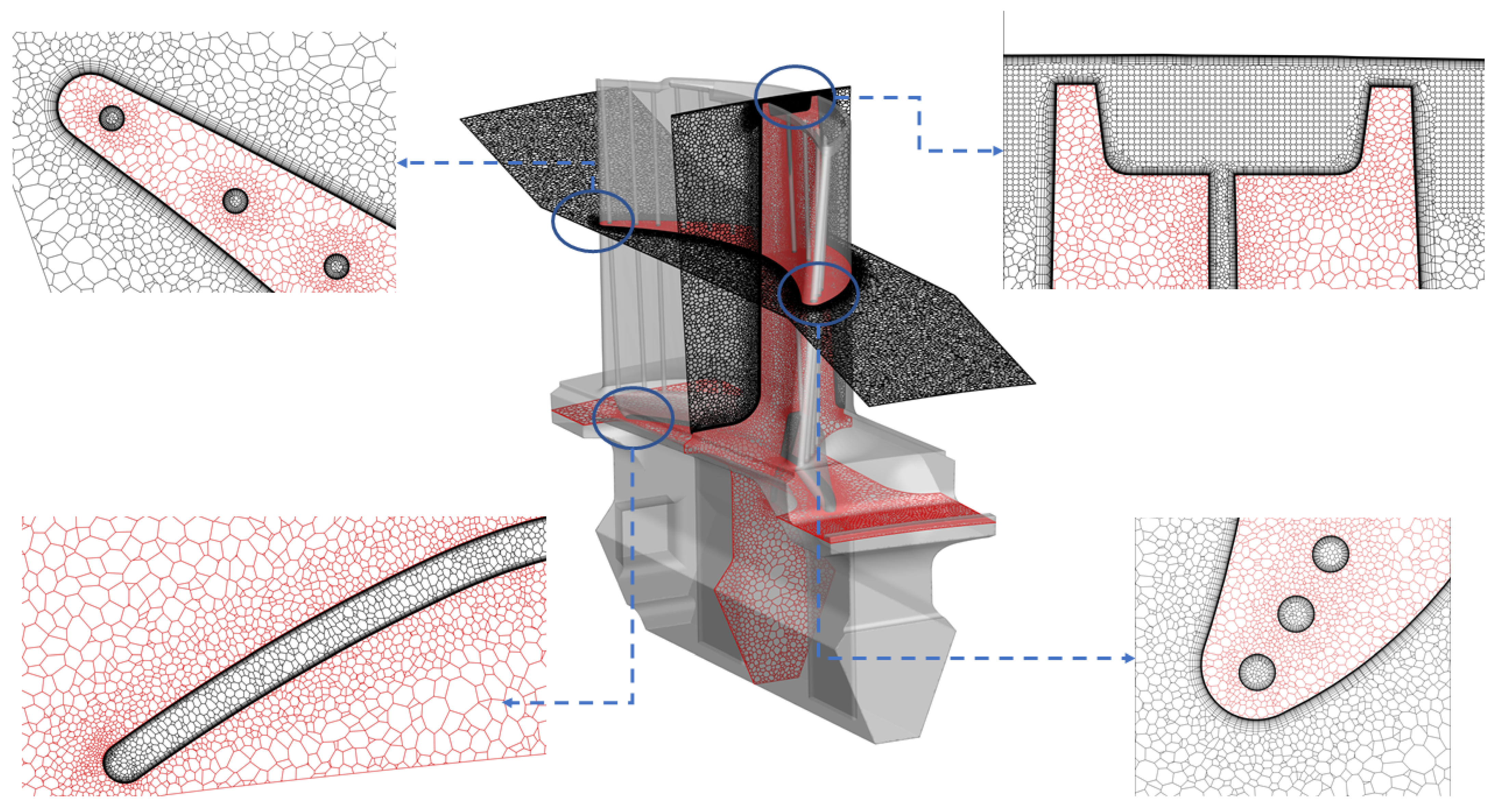
CHT is solved all over the blade profile and the internal walls of the root. The other solid walls, namely the casing and the external root surface, are treated as adiabatic. For the numerical simulations, the fluid and solid meshes are generated directly by Simcenter STAR-CCM+. Polyhedral and prismatic elements are used to generated a hybrid mesh where 15 prismatic layers are enforced to solve the main-flow boundary layer, whereas 10 prismatic layers are enforced to solve the coolant boundary layer. The average y + over the blade profile is ≈1, with a maximum value close to 1.2 close to the tip region, due to the presence of the tip leakage vortex (TLV). As far as the internal channels are concerned, the average y + is equal to 5, mainly because of the high turbulent region close to the inlet sections of the channels. The target mesh size is around 1.5% of the blade axial chord, while the surface mesh dimension over the blade profile is equal to 0.5% of the axial chord. A mesh refinement procedure is enforced to solve the interaction between coolant and main-flow over the tip gap. In this region, the average mesh size is equal to 1/3 of the global size. The final mesh contains ≈13.5 M elements. Both the periodic and the solid/fluid interfaces are discretized with conformal meshes. Detailed views of the computational mesh are reported in Figure 4. More details about the selection process of the computational mesh can be found in Baratta et al. [18], where the numerical methodology is also validated through the simulation of the C3X Vane Hylton et al. [19], whose experimental data are available for the validation of CHT approaches. Concerning the mesh sizing, the grid density of the present case is coherent both with the one showed for the C3X case in Baratta et al. [18] and with the elements density used for the cooled MT1 vane in Griffini et al. [20].

4. Aerodynamic Performance of the Selected Configurations

This section reports the results of the numerical analysis performed on the different considered configurations. First, the main characteristics of the flow field associated with the reference case (bare anima, BA) are introduced, focusing on how the latter governs the distribution of the coolant. Next, the suitability of each optimization in weakening the vortical structures and smoothing the flow field is discussed. All the flow field visualizations are reported in Figure 5.

4.1. Reference Case: Bare Anima

In the original design, the cold fluid is drawn from a large plenum in the hub by two feeding ducts, running through the root. Eventually, the two ducts join by mean of a U-junction, and extend in the leading and trailing direction, thus forming a plenum chamber from which the radial cooling channels of the blade are fed. As a result of the sudden expansion occurring at the entrance of the plenum chamber, vortical structures arise in the region right above the U-junction, referred to as ‘core’ hereafter, and in the leading and trailing branches (Figure 5a.)
The two counter-rotating vortices in the core resemble the flow past a bluff body, but the trailing core vortex (TCV) appears stretched and oblong, whereas the leading core one (LCV) is compressed and retains a smaller size. This flow pattern, arising from a symmetric geometry, is imposed by the asymmetric requirement of mass-flow rate, chiefly dictated by the three larger-diameter cooling channels of the leading edge. Vortex formations are detected in the leading (LEV) and trailing (TEV) sides as well, due to the sharp turns that drive the flow into the enlarged chamber. The existence of two stagnation spots downstream from the feeding ducts is assessed for in the proximity of channels 3–4 and 10–12. The back-flow originating in these areas recirculates in the previously described vortical regions, thus contributing to their formation and further reinforcing them. Eventually, the feeding mechanism could be summarised as follows: the flow coming from the feeding ducts reaches the stagnation regions where it partly moves along the inlets wall to feed the channels; the flow is also partly captured by the vortices and recirculates in the plenum before entering the cooling channels. The resulting distributions of coolant mass-flow rate normalized by the blade inlet mass-flow rate and the coolant temperature at the channels inlet normalized by the blade inlet relative total temperature at mid-span for the BA case are reported in Figure 6.
The rather complex flow field discussed above involves several dissipating phenomena that are liable to induce aerodynamic losses. The flow path in the BA configuration is also responsible for the non-homogeneous distribution of the coolant flow rate and inlet temperature among the fifteen cooling channels. However, such solution does not negatively affect the cooling performance of the system. Still, it hints at possible redesign strategies for future modifications.
To account for the distribution of coolant flow rate and inlet temperature, two suitable coefficients are defined for each channel:
D M , i = m ˙ m a x m ˙ i m ˙ m a x ,
D T , i = T i T m i n T m i n .
The left-side term in Equation (1) refers to the mass-flow rate distribution coefficient for the ith channel, the one in Equation (2) to the temperature distribution coefficient for the same channel. The reference values m ˙ m a x and T m i n are, respectively, the maximum coolant flow rate and the minimum inlet temperature of the fifteen cooling channels, whereas m ˙ i and T i are the values relative to the ith channel. As the coolant flow rates of the first three channels and the ones of the remaining thirteen are not comparable, two different reference values are used for the sets 1–3 and 4–15. The distribution coefficients hold positive values, whose magnitude indicates how much a channel is penalized with respect to the optimal conditions (e.g., maximum mass-flow rate/minimum temperature delivered uniformly at each channel).
The obtained scenario for the bare anima is reported in Figure 7. The uneven profile of coolant inlet conditions is seemingly correlated with the presence of vortices. Indeed, the 3rd and the 1 channels, located in the proximity of the stagnation areas and relatively far from the vortices, hold the higher coolant flow rates. The third also shows the lowest inlet temperature. The trend of non-homogeneity generally increases from the extremes of the interval 5–10 towards the centre, reaching peaks up to 13 % for the mass-flow rate and 18 % for the temperature. Likewise, the reduction arises as the flow enters the side branches, from the 3rd to the 1st and from the 13th to the 15th channel. This behaviour is more evident for the temperature distribution, whereas the coolant flow rate coefficients shows a sort of plateau for channels 2–3 and 13–14 and a sudden surge for the edge channels. It can also be inferred that the inlet temperature of the channels at the trailing side are generally higher than the one at the leading side, given the higher flow velocity in the leading than in the trailing duct.

4.2. Modified Geometries: Pins, Drivers, and Diffuser

The modifications to the flow field and their impact on the coolant inlet conditions, achieved with different plenum designs, are the main topic of the present section. The results are firstly presented for the flow-perturbing solutions (i.e., vortex breaker and flow driver), then for the streamlined shape configuration. For each configuration, the discussion of the results is preceded by a detailed description of both the geometry and the intents pursued with such modifications, along with the expected feasibility of the technology.

4.2.1. The Vortex Breaker

In the vortex breaker solution an array of staggered cylindrical pins is located in the core region of the anima, where large vortical structures have been detected. The pins are arranged on three rows, each of them composed either by four or five elements. The centre-to-centre horizontal distance measures two diameters, the vertical one 1.73 diameters, so that all the pins are evenly spaced. The aim of the pins array is to interfere with the vortices formation, breaking them down into smaller structures, so as to reduce the recirculation in this area and provide smoother coolant conditions to the core channels. The effects of interfering objects placed in the wake of bluff body has been investigated by Cete and Unal [21], Igbalajobi et al. [22], Ozono [23], Liu et al. [24] and Gim et al. [25]. The previous studies deal with the influence of a splitter plate on the flow past a cylinder, except for the last one where the interfering object is a rod. In all the cases, the presence of geometrical features in the wake region proves to be effective in reducing the turbulence levels and the interactions between the vortex pair. Assuming that the two counter-rotating vortices observed in the core of the anima can be assimilated to a bluff-body instance, the vortex breaker solution represents an alternative for the control of vortex formations.
Percentage variations and distributions of both coolant flow rates and inlet temperatures are reported in Figure 8. As it can be observed in Figure 5d, the flow still recirculates in the core, but the large vortex formation taking place in the BA case is no longer present. The flow field outside the core region is virtually unaffected. The percentage variations of the coolant inlet conditions with respect to the reference case are reported in Figure 8a,b.
The impact of the vortex breaker design on the coolant inlet conditions is quite limited. The coolant flow rates of the core channels (4–10) grows in the range of 2 % to 4 % . The effect outside such region is mostly negligible. The inlet temperatures generally decrease, but changes are below the 2 % . Consequently, the distribution profiles (Figure 8c,d) are almost unaltered, even though they show a faintly smoother trend.

4.2.2. The Flow Driver

In the flow driver solution, a pair of aerodynamic profiles are embedded on the two sides of the U-junction and designed to guide the flow inside of the critical core region, favouring the expansion in the plenum chamber and easing the delivery of the coolant to the central channels. The use of such airfoils is quite widespread in industrial applications when it comes to guiding the flow through complex paths. For instance, such solution is adopted to drive the coolant flow in the sharp 180-degree turns typical of the multi-pass cooling ducts featured by modern gas turbine blades.
The flow field generated by the FD presence is reported in Figure 5c. Part of the cooling flow is deflected towards the core region, thus reaching the channels’ inlet by circumventing the stagnation areas. Moreover, the core vortices show an almost symmetric structure. The downside of this design is the formation of wakes behind the two profiles, which generates recirculating regions right before the inlets of the cooling channels.
The modifications brought by the flow driver (Figure 9) are more marked than the ones observed with the vortex breaker. The adoption of this design attains beneficial effects on the coolant flow rate of the core channels, leading to an increase up to nearly 5 % (Figure 9a). However, the leading side channels 1–4 undergo a corresponding decrease down to 4 % . Moreover, despite the lower inlet temperature of channels 5–7 and 13–15, a remarkable surge is observed for the first four and 9–10 channels. Such phenomenon is to be ascribed to the flow being heated up in the recirculating wake behind the airfoils (Figure 9b). The reason for the noticeable rise of the coolant inlet temperature for the first four channels can also be ascribed to the fact that the leading-side aerodynamic element shoves the fluid inside the core, prolonging the flow path that leads to the channels that require the highest flow rate. The resulting profile of the coolant flow rate (Figure 9c) proves for a smoother core region distribution, whilst no major changes arise for the remaining channels. Noticeable modifications appear in the inlet temperature profile (Figure 9d). The distribution in the core channels 5–8 drops around or below 10 % and a planer distribution is observed for the trailing branch channels. A detailed study about the impact of the FD stagger angle on the flow recirculation and the cooling channels performance is out of the scope of the present activity and is not currently planned.

4.2.3. The Diffuser

In the diffuser solution the two feeding ducts are merged into a single duct. The inlet area of the single duct sums up to the total inlet area of the original design. The side walls of the duct features a diverging slope of 7 , meant to slow down the flow before the entrance in the plenum chamber. Moreover, the leading and trailing branches have been reshaped. Their cross-section has been reduced, in agreement with the amount of coolant flow rates that they are supposed to carry, and they have been assigned with a converging shape, so that, as the flow is delivered to the lateral channels, the velocity in the branches remains constant. The streamlined shape of the diffuser aims at suppressing any instance of vortex formation, eliminating the critical core region and providing a better design of the lateral branches. As from the evidence of the previous paragraphs, such a result cannot be achieved with the insertion of flow perturbators. However, this solution requires the full redesign of the secondary air system, rather than mere geometrical modifications, so the structural integrity of the new design should be carefully assessed for.
The aerodynamic-compliant shape of the diffuser, in conjunction with the deceleration imposed by the divergent sector of the duct, produces a smooth flow path. As it can be observed in Figure 5d, each instance of vortical structures has been nearly suppressed and the fluid moves in a tidy fashion from the entrance of the duct to the inlet of the cooling channels. Residual vortices still arise from the expansion in the leading and trailing branches, but their intensity is significantly reduced by the proper flow guidance provided by the new design. Back-flows are not present, as the coolant flow impacts on larger area of the inlet walls and with lower velocity. Then, the associated recirculation of cooling flow is eliminated.
The percentual variations of the coolant inlet conditions with respect to the reference case are reported in Figure 10. The modified design brings some benefits to the core-region channels, which experience an overall rise of the coolant flow rate (channels 5–9, Figure 10a) and a drop of the inlet temperature (channels 5–8) down to nearly 10 % (Figure 10b). In particular, channels from 2 to 4 undergo both the reduction of the coolant flow rate and the increase in the inlet temperature, whereas the channels in the trailing branch are only weakly affected. Nevertheless, the diffuser configuration allows for smoothing the coolant inlet conditions, especially in the core region (channels 5–8, Figure 10c,d). Here, the coolant flow rate distribution is stable around 7 % and the temperature distribution is well below 5 % .
It should be noted that critical regions arise in the diffuser design (channels 4 and 10). Moreover, the smoother trend observed for temperature distribution is partly due to the overall raise of temperature, caused by the flow slowing down in the divergent duct and exchanging more heat with the walls. Given the well-ordered flow path and the virtual absence of vortical structures inherent to this design, the causes of the remaining distribution over the central channels observed could be ascribed to external factors, such as the channels outlet conditions and the uneven requirement of the mass-flow rate. This makes the diffuser a reference case to assess for the effectiveness of flow perturbators solutions in reducing the vortex formations. As far as LE and TE channels are concerned (1–3, 13–15), the sudden expansion necessary to govern the coolant flow rate still brings about losses.

5. Impact of Configurations on Blade Temperature Profile

This section is dedicated to the analysis of the effect of the coolant inlet conditions variations on the thermal condition of the blade by showing the variation of temperature profiles on the pressure side (Figure 11), the suction side (Figure 12), and inside of the blade (Figure 13).

5.1. Reference Case: Bare Anima

First, the main features of the blade temperature field in the case of the BA configuration are presented. Figure 11a and Figure 12a show the normalized temperature profile T / T r e f on the blade pressure side (PS) and suction side (SS), respectively. On the PS, temperature holds a radial trend, generally soaring from the platform to the tip. High temperatures are detected on the leading edge (LE), due to the main-flow stagnation. In contrast, the region just downstream from the leading edge is visibly colder than the rest of the blade, at equal span, despite retaining the same radial trend. The profile on the SS is slightly different: although temperature still tends to rise from platform to tip, the maximum is achieved at about 70 % of the span. Afterwards, colder regions emerge. Such behaviour is partly explained by the boundary conditions set at the main-flow inlet (Figure 3) and by the development of the passage vortex, though the main reason is the ejection of exhaust coolant from the blade tip. Still, high temperature spots can be detected in the near-tip regions: the stripes visible a the trailing edge are ascribed to the thickness of the blade in the TE region, so that the cooling effect of the channels is still evident on the blade surface. The temperature profile here described is in good agreement with the work of Takahashi et al. [6] on a similar blade and cooling geometry.
Figure 13a depicts the temperature distribution inside the blade. Coherently with the observations made for the external surfaces of the blade, temperature generally increases from low to high spans. In addition, temperature grows from the camber line, where cooling channels are located, to the external surfaces. The cooling of the trailing edge (TE) appears more critical with respect to the LE, confirming the results of Sierra Espinosa et al. [7]. Such behaviour is connected to the thin section of the blade in this region, which does not allow for allocating numerous cooling channels. It can be observed that the intense cooling of the LE provides adequate protection along the whole blade height, with the sound exception of the region closer to the nose, where the effects of the external flow are dominant. Furthermore, in the mid-chamber one (approximately, from channel 6 to 12), despite the high density of cooling channels, the amount of metal to be cooled down is very high, and high temperatures start developing on the external surfaces from 50 % span on. However, it should be noted that the larger section of the blade in this region provides a higher structural strength if compared to the thin section of the TE. Hence, the temperature increase does not represent a harmful condition for the blade.

5.2. Modified Geometries: Pins, Drivers, and Diffuser

The impact of new SAS geometries on the thermal performance of the blade is here discussed. Panels b–d of Figure 11, Figure 12 and Figure 13 report the absolute variation of temperature with respect to the reference temperature Δ T / T r e f on different zones of the blade for the three new configurations. Generally speaking, the modification of the temperature field echoes the changes observed in the coolant inlet conditions. In fact, a colder region originates in the middle of the blade, reflecting the modified conditions of the core channels, whereas the regions of the trailing and leading edge are hotter. Moreover, the magnitude of the temperature variations is coherent with the ones observed for the coolant properties. The configuration with the diffuser presents the largest changes whereas the one with the vortex breaker is almost unaffected. Temperature variations are higher in the interior of the blade, while they are strongly mitigated on the external surfaces, where the heat flux is mainly dictated by main-flow convection. Variations on the PS are generally more conspicuous than the ones on the SS. An exception arises in the high-span region of the SS, where largest temperature variation spots are detected. This is related to the discharge of coolant from the blade tip.
The VB configuration has a negligible effect on the external surfaces of the blade (Figure 11b and Figure 12b). Looking at Figure 13b, it may be argued that VB geometry produces an overall temperature reduction in the middle-region of the blade. Still, normalized temperature variations are mild, well below 0.02 . Considering the variation of coolant inlet conditions discussed in the previous section, it appears that a percentage variation below 2.5 % in the coolant flow rate does not produce sensible changes in the temperature profile of the blade under study.
Temperature variations induced by the FD geometry are more significant. It can be seen that the Δ T / T r e f value extend mildly to the external surfaces by ± 2 % on the PS (Figure 11c, close to the leading edge) and by ± 5 % on the SS (Figure 12c, close to the tip clearance region). Inside the blade (Figure 13c), the colder region reaches 5 % in terms of Δ T / T r e f . More in details, at the leading edge a cold and a hot region are found close to channel 1, and they revolve around the channel axis as higher spans are considered. This behaviour cannot be solely explained by the variation of the coolant inlet conditions. In fact, such distribution can be traced back to the different temperature profiles at the inlet of channel 1 in the BA and FD configurations, which produces different cooling conditions on the channel surface. The apparent rotation of the two regions is explained by a vorticity component directed along the channel axis. Then, the FD configuration demonstrates that significant modifications of the blade temperature field can be achieved with variation of the coolant conditions around 3 to 4 % .
The most significant results are achieved with the DIFF configuration. In Figure 11d and Figure 12d the formation of the central colder area ( Δ T / T r e f 5 % ) is clearly visible both on PS and SS surfaces. However, hot regions can be spotted at the LE and TE, near the platform. The underlying reason is the nearly total suppression of vortices in the anima achieved with the diffusing geometry (Figure 5d). Besides the improvement of coolant properties, the heat transfer on the anima surfaces is reduced, and the cooling of the disk is consequently affected. This effect propagates to the platform and the low-span regions of the blade which are not interested by the improved cooling conditions. It should be noticed that the adiabatic condition imposed on the disk surface may emphasize the formation of colder regions, and that heat conduction with the other pieces of machinery would supposedly produce a smoother temperature profile.
The LE of the blade in the DIFF case is interested by the same phenomenon described for the FD configuration. The extreme region of the TE undergoes an increase in temperature, dictated by the deterioration of coolant conditions observed for channel 15 (Figure 10a,b). Figure 13d highlights the formation of the hotter regions at low spans and around channel 15. Conversely, the mid-chamber region of the blade benefits from a remarkable decrease in temperature, extending from PS to SS. It has already been stated that the centre of the blade is a critical region, due to the large amount of metal to cool. Thus, the modifications brought by the DIFF geometry can be considered as an improvement of the thermal performance. In addition, the DIFF configuration demonstrates that conspicuous improvements in the thermal performance of this blade can be achieved with beneficial variation of the coolant inlet conditions above 5 % .
Table 1 reports the average normalized temperature variation Δ T / T r e f ¯ and the homogeneity (represented by the normalized standard deviation σ T / T r e f ¯ ) of the temperature field on the blade volume and on the blade external surfaces. The DIFF configuration succeeds in lowering the average temperature both inside the blade and, slightly, on the external surfaces, and provides a smoother temperature field, reflecting the improved distribution of coolant. The other two configurations have no sensible impact on the average temperature, even though the VB produces a generally cooler external surface. As far as the temperature homogeneity is concerned, both VB and FD produce a slightly smoother field in the interior of the blade if compared to the DIFF, whereas the opposite effect is obtained on the blade profile.

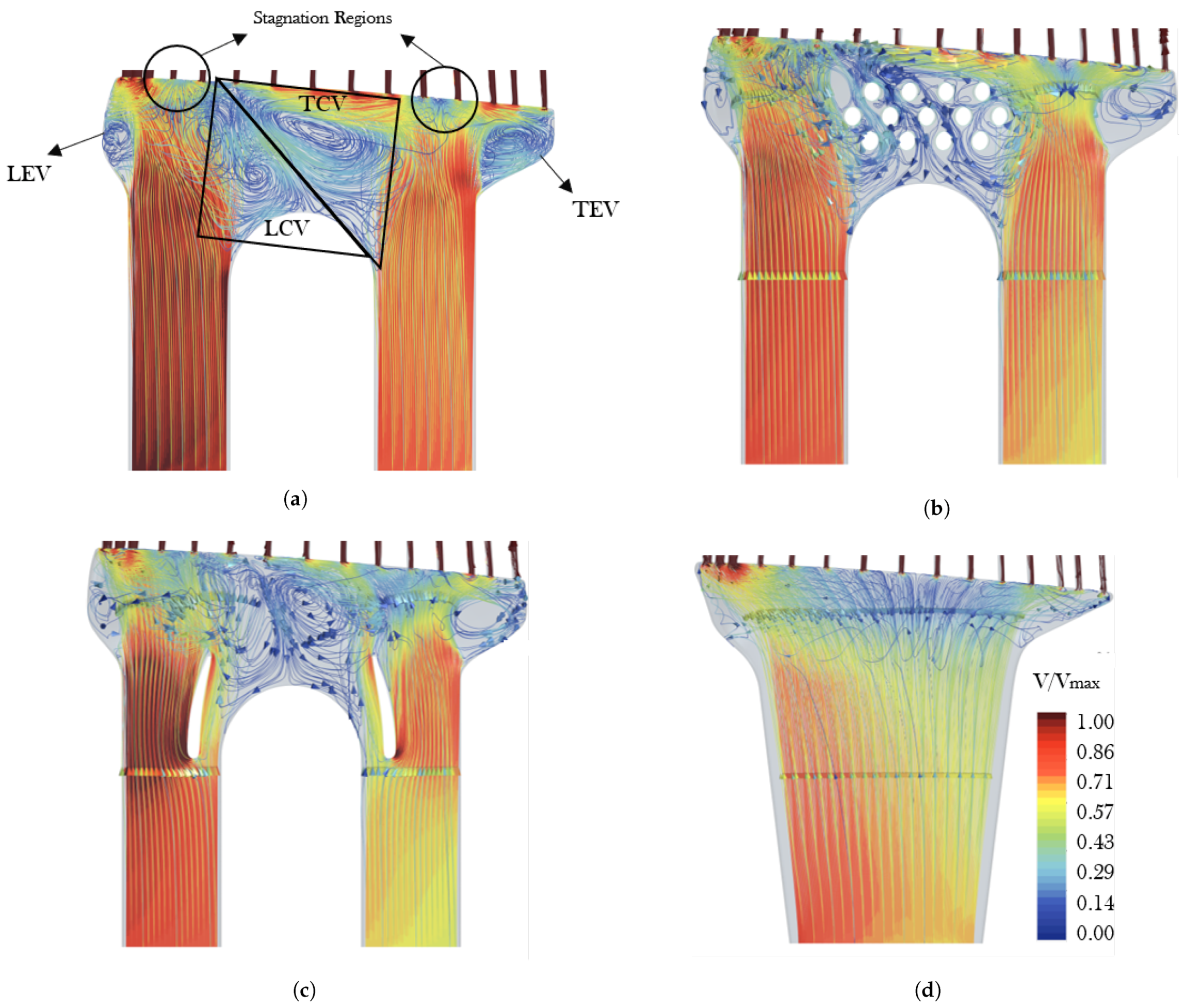
6. Impact of Configurations on Tip Cooling and Tip Vortex

The flow field field in the tip region of the blade is shown in Figure 14 over an axial slice corresponding to channel #5. With reference to the BA case (Figure 14a) the main flow structures can be summarized according to seven different zones developing in the tip clearance and in the squealer, namely:
  • Hot flow penetration inside of the squealer from the pressure side;
  • Casing pressure side streak due the transport of the cold flow towards the pressure side under the drag in the relative frame operated by the casing wall;
  • Suction side relative flow transport inside the squealer;
  • Squealer pressure side streak due to recirculation of upstream cold flow in the squealer;
  • Coolant penetration and bending inside of the squealer;
  • Squealer suction side streak due to flow recirculation inside the squealer;
  • Tip leakage vortex (TLV).
The various phenomena are inherently dependent on the blowing conditions of the cooling channels, which in turn depend on the internal geometry of the SAS and on the adoption of the internal features that redistribute the coolant over the cooling channels. The VB configuration (Figure 14b) presents no relevant difference with respect to the BA case. Major differences are found for the FD (Figure 14c) and the DIFF cases (Figure 14d). The former is characterized by the highest penetration of the coolant in the radial direction towards the casing. This allows for more room for the hot flow entrainment in the tip region, close to the suction side of the blade.
The DIFF case features a similar penetration of the coolant with respect to the FD case: despite that, the entrainment of the hot flow close to the suction side is prevented by the larger entrainment of the cold flow inside the squealer (the DIFF configuration features the lower coolant flow rate at the LE channels from #1 to #4). That outcome is also visible on the left of the coolant core, closer to the pressure side, where the colder region for this case is wider.

6.1. Blade Tip and Squealer Region

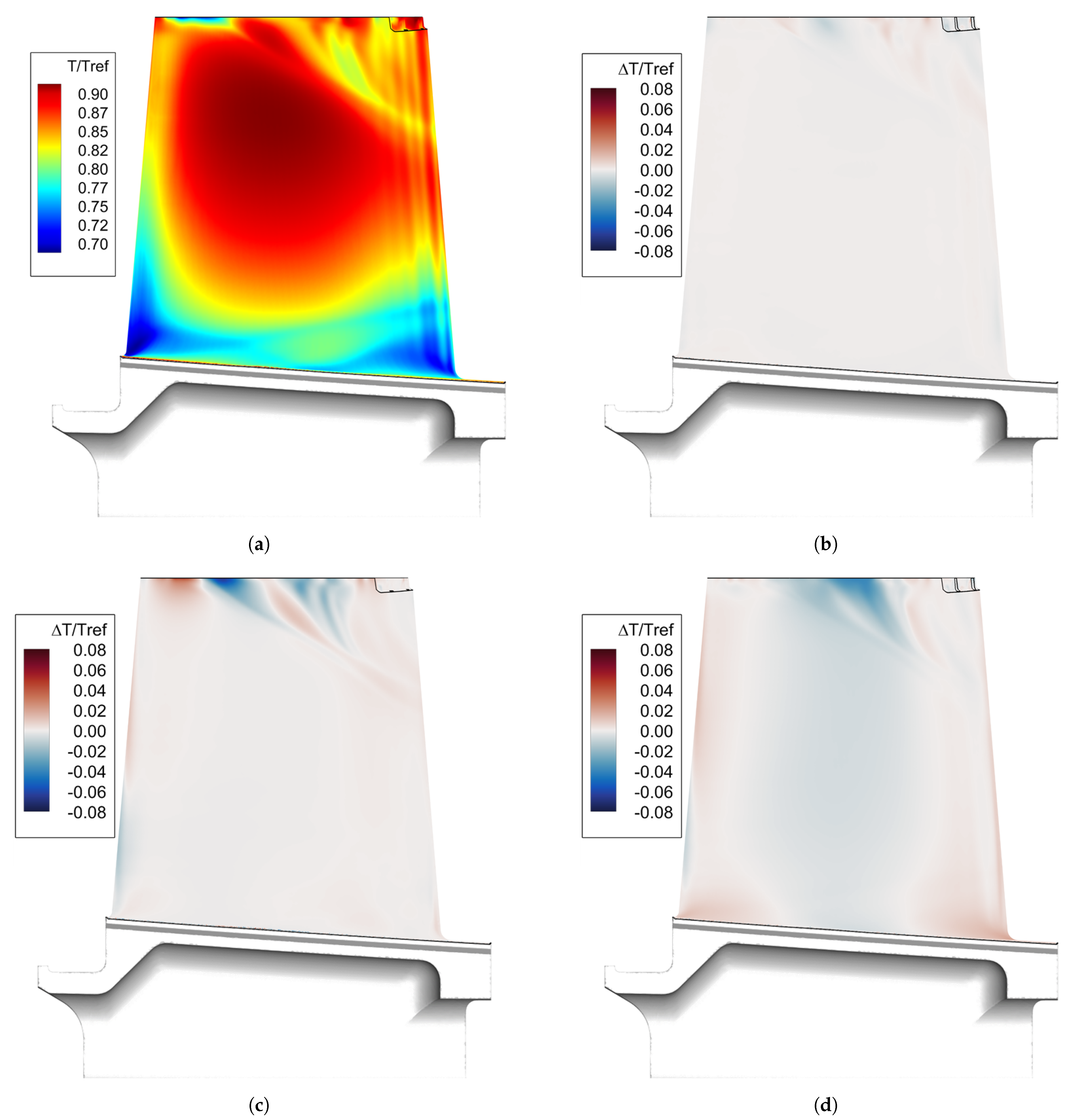
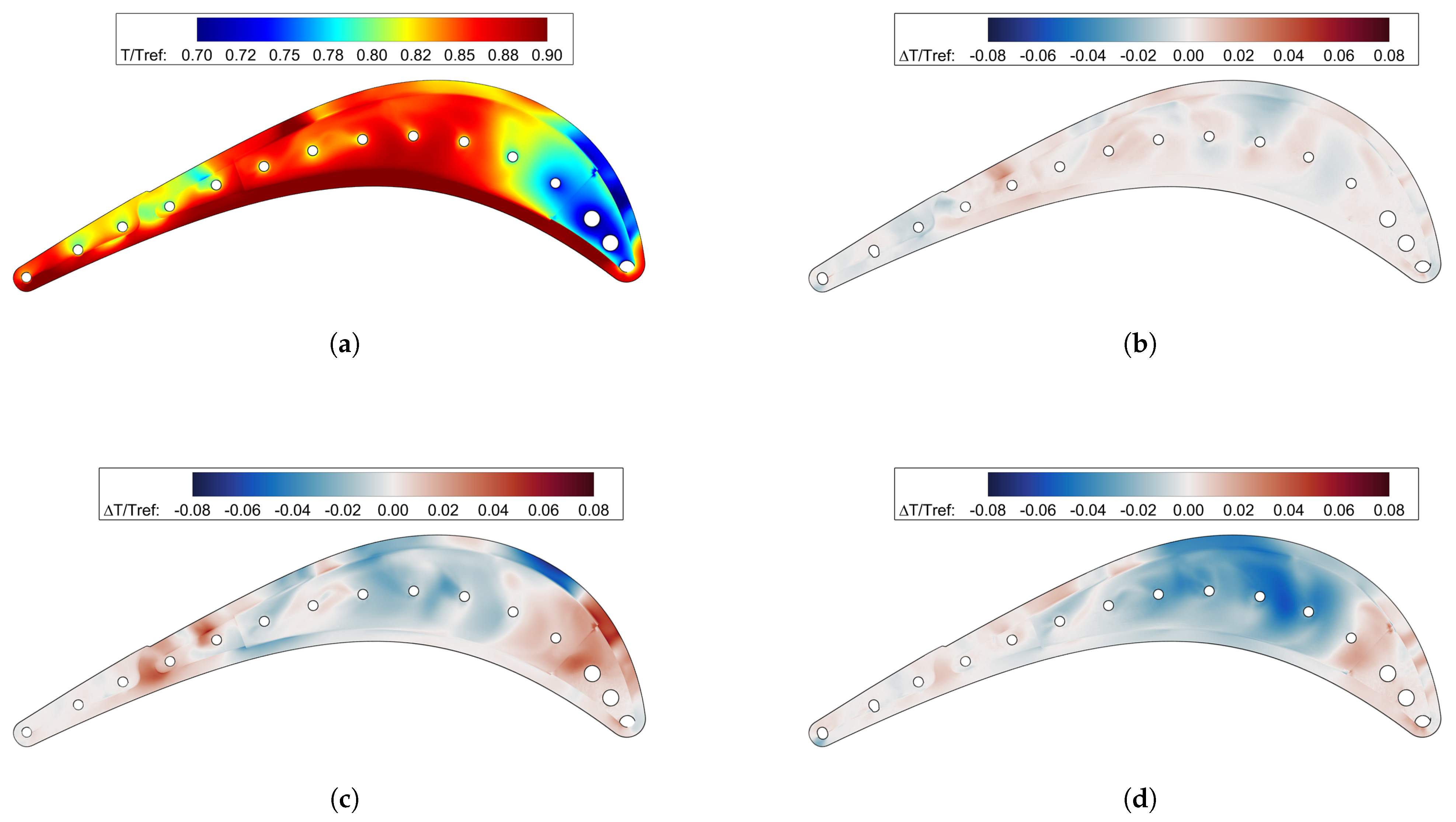
The effect of coolant flow rates and outlet temperature redistribution along with the solid thermal conduction on the tip surface is depicted in Figure 15a) along with the normalized temperature differences ( Δ T / T r e f ) for each configuration. The VB case (Figure 15b) does not feature relevant differences from the reference configuration, which is in accordance with the minor modifications introduced by this geometry on the ejection of coolant at the tip. The same does not hold for the other two cases (Figure 15c for FD and Figure 15d for DIFF), for which the tip region at roughly half axial chord features a lower temperature with respect to the BA case up to Δ T / T r e f 0.08 . Looking at the FD configuration, the hot spot visible in Figure 15c between the third and fourth channel ( Δ T / T r e f 0.07) suggests that the ingress of flow from the SS in the LE region of the blade is enhanced with respect to the BA case. On the contrary, the egress of coolant is delayed, leading to the a cold spot ( Δ T / T r e f 0.08) over the blade tip in correspondence of the firth. Concerning the DIFF configuration (Figure 15d), no hot spot is visible between the third and fourth channel, which suggests that the coolant recirculation in the LE region prevents the penetration of more hot flow from the suction side into the squealer tip, thus maintaining the same temperature level of the BA case.
As far as the central region of the squealer is concerned, lower temperatures are found in correspondence of the channels from the fifth the eighth for the FD ( Δ T / T r e f 0.3) and the DIFF ( Δ T / T r e f 0.5) configurations. They both show a higher temperature close to the LE. The cooling of the squealer tip can be ascribed to two different phenomena: coolant recirculation inside of the squealer and radial thermal conduction through the solid. As was shown in Figure 14, the FD (Figure 14c) and DIFF (Figure 14d) configurations highlight a higher penetration of the coolant in correspondence of the fifth channel, which for the FD case allows for hot gas entrainment in the squealer region. This is not in accordance with the lower temperature found in the central region of the tip, suggesting that the reduction of temperature has to be addressed to the heat transfer with the colder solid (Figure 13c). This also explains the higher temperature found in correspondence of the LE channels. This effect is enhanced for the DIFF configuration, which features both an attached coolant in the squealer (Figure 14d) and the lowest solid temperature (Figure 13d).

6.2. Blade Suction Side and Tip Leakage Vortex

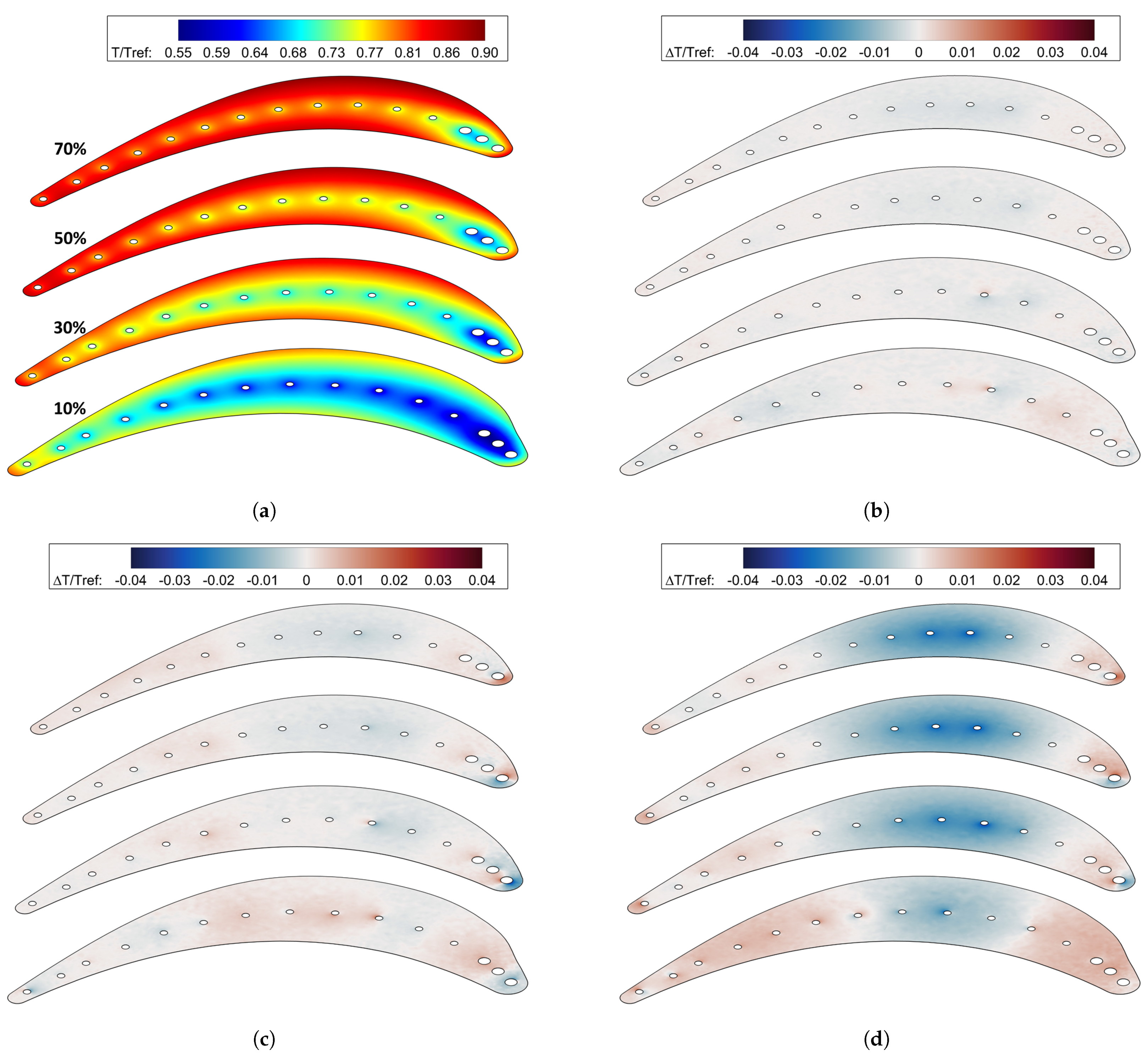
The effect of the internal geometry coolant redistribution over the tip also affects the thermal load over the blade suction side, where the leakage flow tends to move under the pressure gradient. In Figure 16 the difference in temperature on the blade suction side close to the tip region for all the investigated cases with respect to the original configuration is reported.

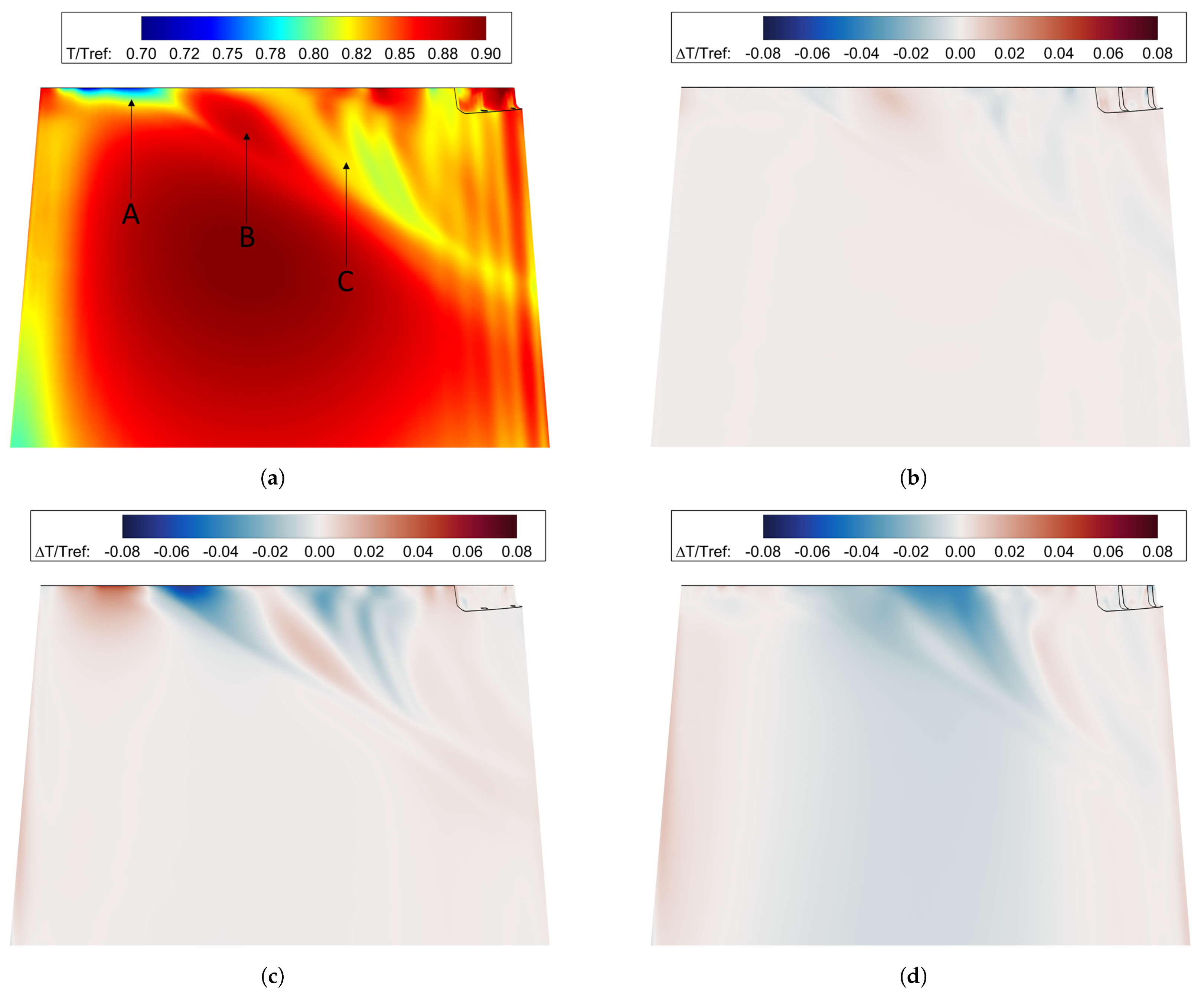
6.2.1. Reference Case: Bare Anima

Looking at the bare anima case (
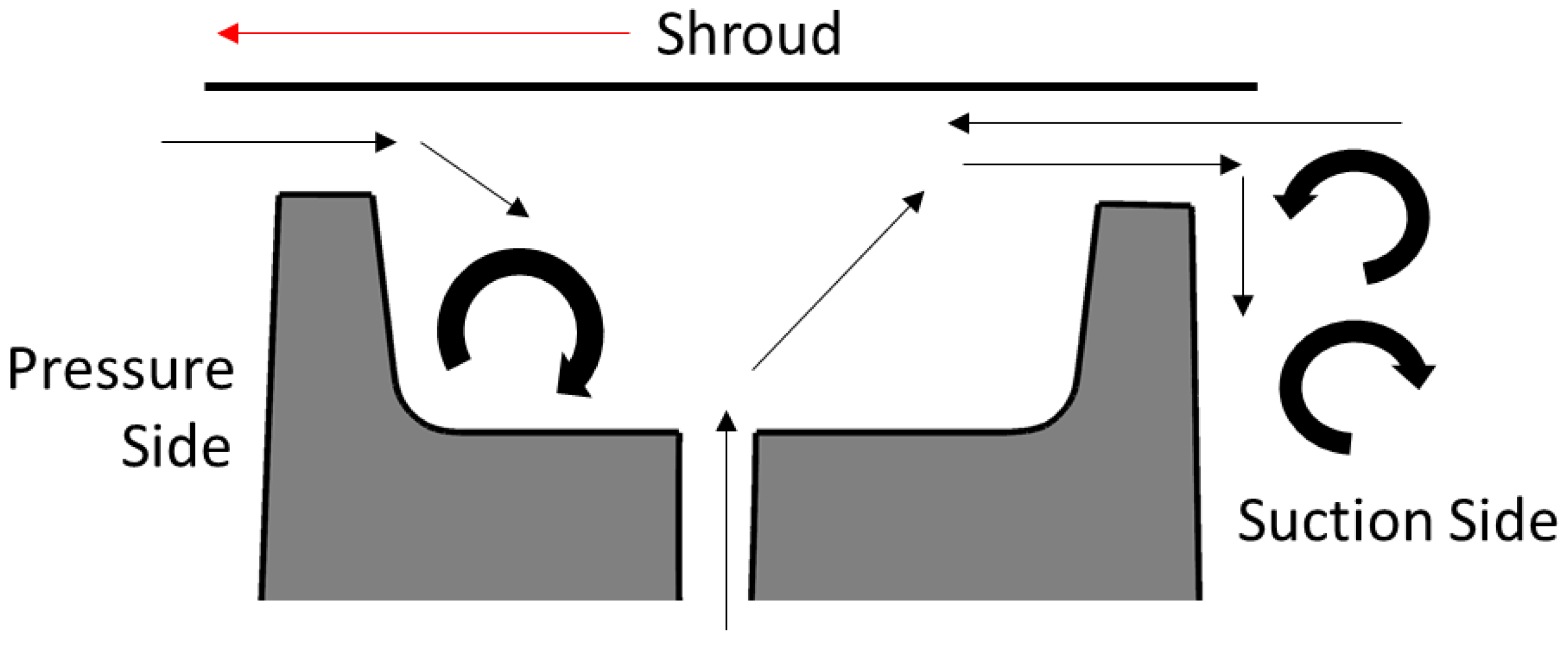
Figure 16a), the ejection pattern over the tip can be summarized as follows: attached coolant close to the LE (A), a temperature peak due to tip leakage flow detachment from the suctions side (B), and cold flow transport lapping over the surface close to the trailing edge (C). The driving mechanism for the definition of the temperature field over the suction side at high span is the interaction between the coolant (that travels across the squealer) and the pressure gradient generated by the blade, which force the coolant to be ejected towards the suction side at a certain axial chord. In fact, the flow close to the casing has a tangential velocity defect in the rotor frame, then is forced to move closer to the suction side interacting with the ejected coolant flow. The relative tangential velocity of the coolant and of the suction side flows are opposite in sign, thus generating radial movement of the flow. That leads to the radially downwards streaks visible from roughly 20% of the chord until the TE. The schematic of the mechanism is shown in Figure 17 (see also Kwak et al. [26] for various configurations of squealer tip).
A detailed description of the impact of that mechanism on the development of the TLV is shown in Figure 18, where the effect of hot gas and tip leakage can be shown for the BA case, while moving along the axial chord, the TLV originated by the coolant ejection at the LE shapes up close to the blade LE (D). The interaction between the SS flow and the coolant affects the tip leakage development, preventing the continuous ejection of coolant from the tip and leading to the detachment of the TLV from the blade. Further downstream, the entrained coolant flows out of the tip, generating a twofold structure: the upper one (F) is generated by the freshly ejected coolant, while the lower one can be addressed to the ejection from the central channels of the blade (E).

6.2.2. Modified Geometries: Pins, Drivers, and Diffuser

Looking at the specific impact of the SAS geometries on the temperature profiles close to the tip on the suction side, it can be concluded that the VB configuration has a negligible impact on the overall temperature distribution (see Figure 16b). On the contrary, the behaviour of the flow for the FD configuration can be appreciated in Figure 16c, where in turn hotter and colder streaks are visible on the suction side close to the blade tip. Concerning the diffuser configuration (Figure 16d), it shows the most promising temperature field, where a Δ T / T r e f 0.06 can be observed in the region where the BA presents a hot spot.
In general, the ejection pattern of the coolant from the squealer shown in Figure 16a for the BA case, remains the same for all the investigated geometries. A local ejection of the coolant from the the LE and local ingress of hot gas into the squealer afterwards can be found before roughly half of the axial chord of the blade. The other configurations are not reported for the sake of brevity. As far as the LE zone is concerned, the only configuration in which some differences can be spotted is the flow driver, whose behaviour was anticipated in the previous treatment of the tip temperature field (Figure 15c). The lower mass-flow rate of coolant at LE channels, deteriorates coolant protection in the zone (A) in Figure 16a. Despite this, the entrainment and later ejection through the squealer favour the decrease in the temperature in the peak zone individuated in the bare anima case (B) in Figure 16a. In the case of the DIFF configuration, where the mismatch between the LE channels flow with respect to the BA case is the highest, the LE temperature remains unaffected. Despite this, the coverage over the central part of the suction side is higher due to more flow entrainment inside the squealer.

7. Conclusions

The present study deals with the numerical analysis of a secondary air system designed for the high-pressure blade of an industrial gas turbine. Along with the reference case, three possible design variations were analyzed; the boundary conditions were unaltered. This study is not aimed at improving the SAS for the blade, which correctly performs in the current gas turbine configuration, but to individuate a possible design strategy for future redesigns. For that reason, the distribution of coolant flow rate as well as metal temperature, and the impact on the development of tip leakage vortex were addressed. Possible manufacturing issues and high-cycle fatigue are not accounted for, as the aero-thermal performance of the blade was the only addressed outcome.
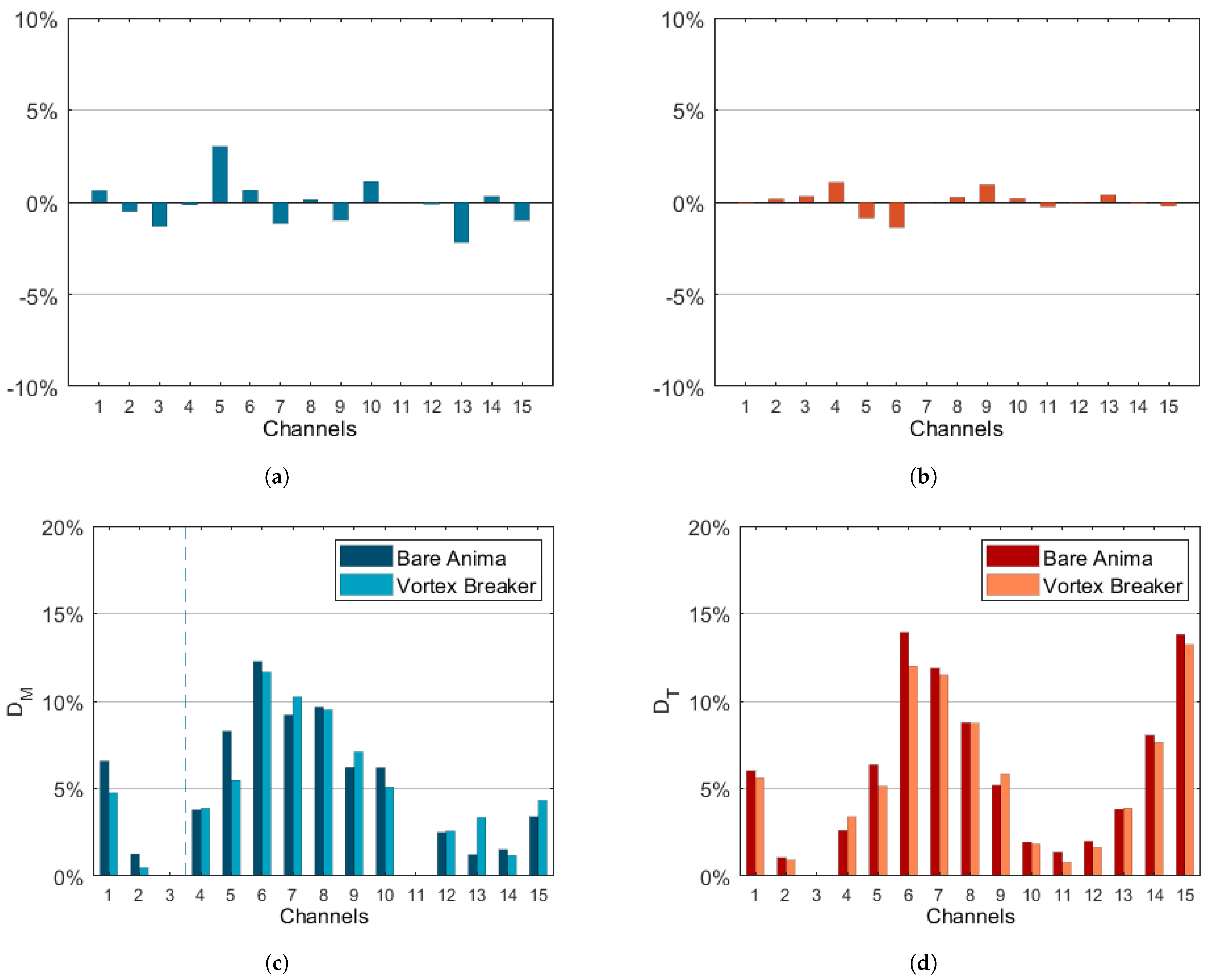
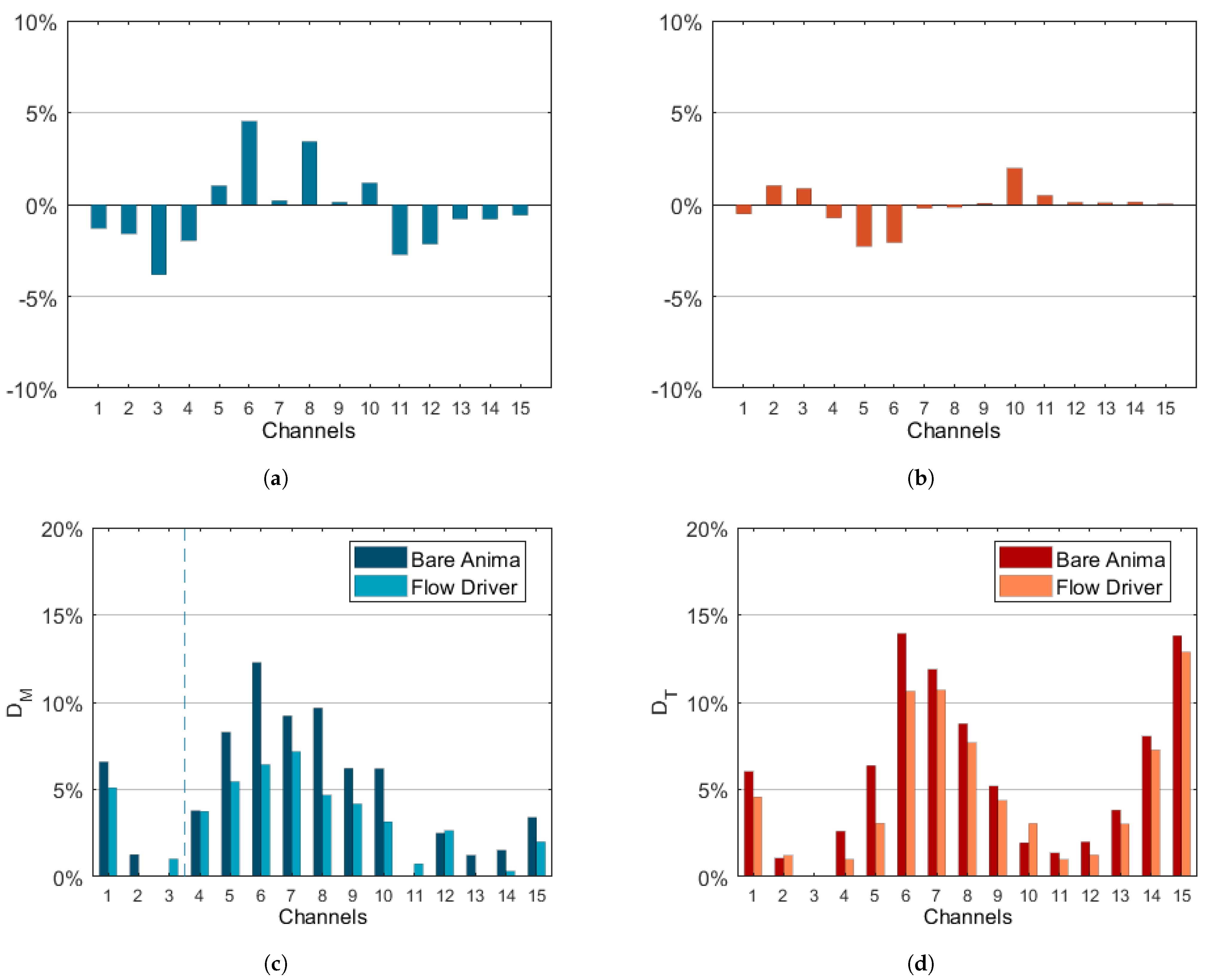
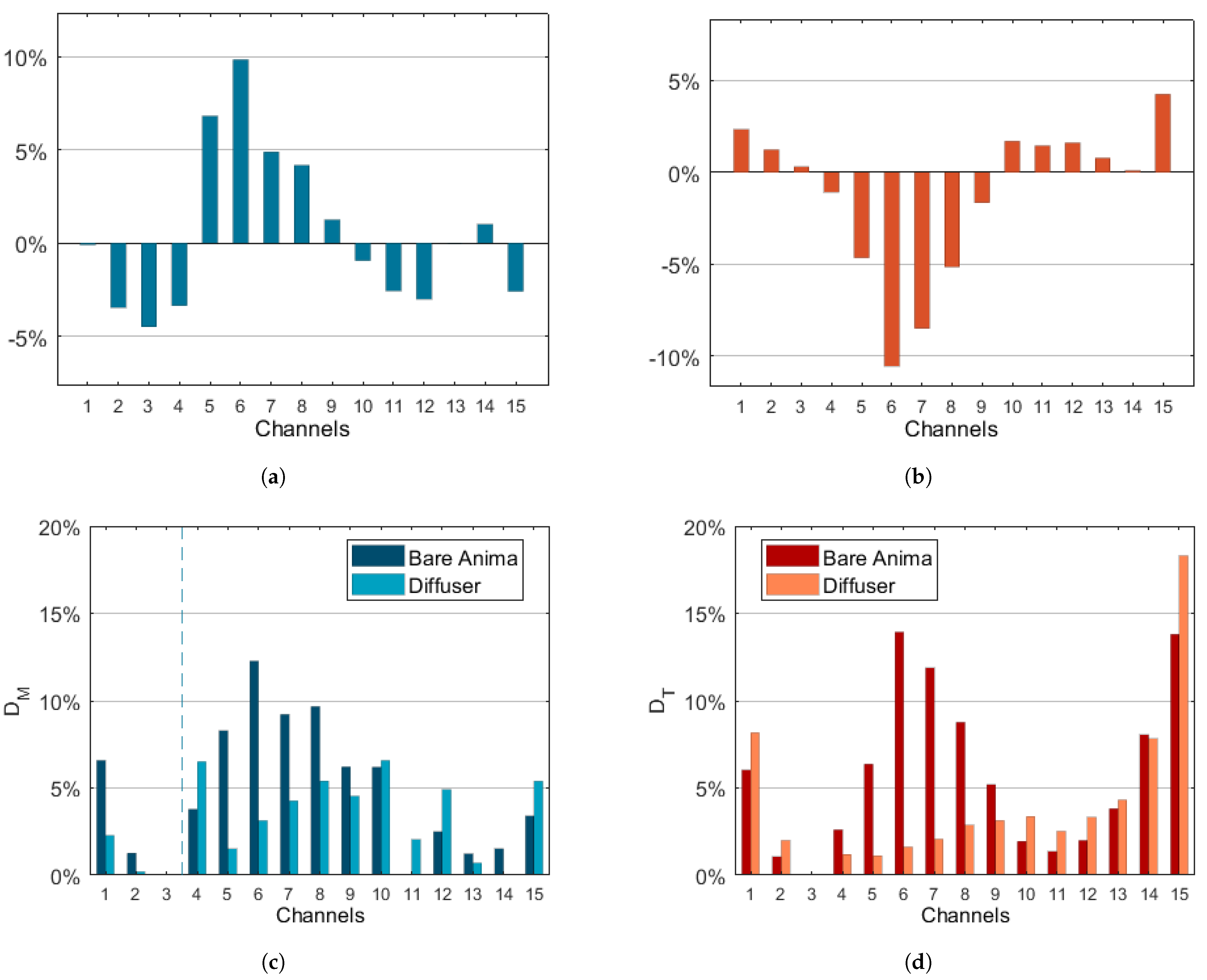
Based on the obtained results, it can be summarized that the introduction of vortex breakers retains a limited impact on the performance of the internal cooling system. In fact, both the mass-flow rate and the temperature maldistribution coefficients feature the same trend and approximately the same values as the bare anima case. The use of flow drivers to split the coolant flow rate among the cooling channels shows some promising results in terms of uniformity. That configuration allows to increase the mass-flow rate fed to the core channels (5–8) as much as almost 5%, resulting in a reduction of the maximum value of the mass-flow rate maldistribution coefficient, which drops well below 10%. This also results in a planer temperature profile at the cooling channels inlet. Still, the impact on the blade metal temperature is limited. The most promising solution is represented by the diffuser-like anima, which allows for a more uniform feeding of the internal channels, in turn reducing the temperature maldistribution coefficient well below 5% over the core channels. Furthermore, the metal temperature in the central part of the blade is reduced. The temperature reduction is as high as 4% of the mid-span inlet relative total temperature. On the other hand, the leading edge and the trailing edge appear to be less protected, especially at low span heights. In fact, an overall increase in the temperature is present around 1%.
Concerning the tip leakage vortex formation, the diffuser-like anima is the most promising solution, also thanks to the uniform distribution of the coolant. Vortex breakers feature no relevant impact on the tip region temperature distribution as well as the tip leakage vortex formation and convection along the passage. Both the flow drivers and the diffuser configurations increase the coolant coverage over the tip region in the central part of the blade. For the flow drivers, this leads to a peak reduction of the temperature of approximately 3%. The diffuser-like shape features a more uniform coolant coverage, with a peak reduction of the temperature close to 5%. However, the flow drivers retain a negative impact on the LE region. Eventually, despite the promising aero-thermal behaviour, the diffuser solution is the least robust option in terms of fatigue, due to the reduced amount of material and to the presence of a single anima with no reinforcements.

Author Contributions

Conceptualization, L.L., N.R., S.S., D.A.M., M.B., L.F., M.V. and M.T.; methodology, L.L., N.R. and S.S.; validation, L.L., N.R. and S.S.; formal analysis, L.L., N.R. and S.S.; investigation, L.L. and N.R.; resources, D.A.M., M.B., L.F., M.V. and M.T.; data curation, L.L. and N.R.; writing—original draft preparation, L.L., N.R. and S.S.; writing—review and editing, N.R., S.S., D.A.M., M.B., L.F., M.V. and M.T.; supervision, D.A.M., M.B., L.F., M.V. and M.T.; project administration, D.A.M., M.B. and L.F.; funding acquisition, D.A.M. and M.B. All authors have read and agreed to the published version of the manuscript.

Funding

This research received no external funding.

Institutional Review Board Statement

Not applicable.

Informed Consent Statement

Not applicable.

Data Availability Statement

Not applicable.

Acknowledgments

Computational resources were provided by HPC@POLITO (http://hpc.polito.it, accessed on 1 September 2020).

Conflicts of Interest

The authors declare no conflict of interest.

Abbreviations

The following abbreviations are used in this manuscript:
BABare anima configuration
CHTConjugate heat transfer
DIFFDiffuser configuration
FDFlow driver configuration
HPTHigh pressure turbine
LCVLeading core vortex
LELeading edge
LVLeading edge vortex
SASSecondary air system
TCVTrailing core vortex
TETrailing edge
TLVTip leakage vortex
TITTurbine inlet temperature
TVTrailing edge vortex
VBVortex breaker configuration
Nomenclature
cSolid specific heat
D M Mass-flow rate maldistribution coefficient
D T Inlet temperature maldistribution coefficient
kSolid thermal conductivity
m ˙ Mass-flow rate
ii-th channel
m ˙ r e f Blade inlet mass-flow rate
m ˙ m a x Maximum cooling channel mass-flow rate
P 02 , r e l Hot gas inlet relative total pressure
P 0 , c o o l a n t Coolant inlet relative total pressure
TTemperature
T 02 , r e l Inlet relative total temperature
T 0 , c o o l a n t Coolant inlet relative total temperature
T m i n Minimum cooling channel inlet temperature
T r e f Inlet relative total temperature at mid-span
VVelocity
V M A X Maximum velocity in anima conduct
Δ T Temperature difference with the reference case
σ Standard deviation

References

  1. Bontempo, R.; Manna, M. Work and efficiency optimization of advanced gas turbine cycles. Energy Convers. Manag. 2019, 195, 1255–1279. [Google Scholar] [CrossRef]
  2. Montomoli, F.; Carnevale, M.; D’Ammaro, A.; Massini, M.; Salvadori, S. Uncertainty Quantification in Computational Fluid Dynamics and Aircraft Engines, 1st ed.; Springer: Cham, Switzerland, 2015. [Google Scholar] [CrossRef]
  3. Haubert, R.; Maclin, H.; Noe, M.; Hsia, E.; Brooks, R. High Pressure Turbine Blade Life Sensitivity. In Proceedings of the 16th Joint Propulsion Conference, Hartford, CT, USA, 30 June–2 July 1980. [Google Scholar] [CrossRef]
  4. Kim, B.S.; Kim, B.S.; Choi, W.; Musgrove, G.O.; McFarland, J.; Fierro, F.; Ransom, D.L. Gas turbine blade stress and temperature sensitivity to turbine inlet profile and cooling flow. In Turbo Expo: Power for Land, Sea, and Air; Volume 8: Turbomachinery, Parts A, B, and C; American Society of Mechanical Engineers: New York, NY, USA, 2012; pp. 2273–2284. [Google Scholar] [CrossRef]
  5. Horlock, J. The basic thermodynamics of turbine cooling. J. Turbomach. 2001, 123, 583–592. [Google Scholar] [CrossRef]
  6. Takahashi, T.; Watanabe, K.; Takahashi, T. Thermal Conjugate Analysis of a First Stage Blade in a Gas Turbine. In Proceedings of the Turbo Expo: Power for Land, Sea, and Air, Munich, Germany, 8–11 May 2000. [Google Scholar] [CrossRef]
  7. Sierra Espinosa, F.Z.; Han, J.C.; Portugal, A.U.; Kubiak, J.; Narzary, D.; Blake, S.; Cadena, F.; Lara, H.; Nebradt, J. Influence of Cooling Flow Rate Variation on Gas Turbine Blade Temperature Distributions. In Proceedings of the Turbo Expo: Power for Land, Sea, and Air, Berlin, Germany, 9–13 June 2008. [Google Scholar] [CrossRef]
  8. Alizadeh, M.; Izadi, A.; Fathi, A. Sensitivity Analysis on Turbine Blade Temperature Distribution Using Conjugate Heat Transfer Simulation. J. Turbomach. 2013, 136, 011001. [Google Scholar] [CrossRef]
  9. Rezazadeh Reyhani, M.; Alizadeh, M.; Fathi, A.; Khaledi, H. Turbine blade temperature calculation and life estimation—A sensitivity analysis. Propuls. Power Res. 2013, 2, 148–161. [Google Scholar] [CrossRef] [Green Version]
  10. Williams, R.P.; Dyson, T.E.; Bogard, D.G.; Bradshaw, S.D. Sensitivity of the Overall Effectiveness to Film Cooling and Internal Cooling on a Turbine Vane Suction Side. J. Turbomach. 2013, 136, 031006. [Google Scholar] [CrossRef]
  11. Nathan, M.L.; Dyson, T.E.; Bogard, D.G.; Bradshaw, S.D. Adiabatic and Overall Effectiveness for the Showerhead Film Cooling of a Turbine Vane. J. Turbomach. 2013, 136, 031005. [Google Scholar] [CrossRef]
  12. Garg, V.K.; Gaugler, R.E. Effect of coolant temperature and mass flow on film cooling of turbine blades. Int. J. Heat Mass Transf. 1997, 40, 435–445. [Google Scholar] [CrossRef] [Green Version]
  13. Prapamonthon, P.; Yin, B.; Yang, G.; Zhang, M. Understanding of temperature and cooling effectiveness sensitivity of a film-cooled vane under coolant inlet temperature effect: A case study. Case Stud. Therm. Eng. 2019, 14, 100505. [Google Scholar] [CrossRef]
  14. Amaral, S.; Verstraete, T.; Van den Braembussche, R.; Arts, T. Design and optimization of the internal cooling channels of a high pressure turbine blade—Part I: Methodology. J. Turbomach. 2010, 132, 021013. [Google Scholar] [CrossRef]
  15. Verstraete, T.; Amaral, S.; Van den Braembussche, R.; Arts, T. Design and optimization of the internal cooling channels of a high pressure turbine blade—Part II: Optimization. J. Turbomach. 2010, 132, 021014. [Google Scholar] [CrossRef]
  16. Puttock-Brown, M.; Rose, M. Formation and evolution of Rayleigh-Bénard streaks in rotating cavities. In Proceedings of the ASME Turbo Expo 2018: Turbomachinery Technical Conference and Exposition, Oslo, Norway, 11–15 June 2018. [Google Scholar]
  17. Menter, F.R. Two-equation eddy-viscosity turbulence models for engineering applications. AIAA J. 1994, 32, 1598–1605. [Google Scholar] [CrossRef] [Green Version]
  18. Baratta, M.; Cardile, F.; Misul, D.A.; Rosafio, N.; Salvadori, S.; Forno, L.; Toppino, M. Redesign of the TG20 Heavy-Duty Gas Turbine to Increase Turbine Inlet Temperature and Global Efficiency. In Proceedings of the Turbo Expo: Power for Land, Sea, and Air, London, UK, 21–25 September 2020. [Google Scholar] [CrossRef]
  19. Hylton, L.; Mihelc, M.S.; Turner, E.R.; Nealy, D.A.; York, R.E. Analytical and Experimental Evaluation of the Heat Transfer Distribution over the Surfaces of Turbine Vanes; Technical Report; NASA Contractor Report, NASA CR-168015; NASA: Washington, DC, USA, 1983. Available online: https://ntrs.nasa.gov/api/citations/19830020105/downloads/19830020105.pdf (accessed on 1 September 2020).
  20. Griffini, D.; Insinna, M.; Salvadori, S.; Martelli, F. Clocking effects of inlet nonuniformities in a fully cooled high-pressure vane: A conjugate heat transfer analysis. J. Turbomach. 2016, 138, 021006. [Google Scholar] [CrossRef]
  21. Cete, A.R.; Unal, M.F. Effects of splitter plate on wake formation from a circular cylinder: A discrete vortex simulation. In Proceedings of the European Computational Fluid Dynamics Conference, Brussels, Belgium, 7–11 September 1992. [Google Scholar]
  22. Igbalajobi, A.; McClean, J.; Sumner, D.; Bergstrom, D. The effect of a wake-mounted splitter plate on the flow around a surface-mounted finite-height circular cylinder. J. Fluids Struct. 2013, 37, 185–200. [Google Scholar] [CrossRef]
  23. Ozono, S. Flow control of vortex shedding by a short splitter plate asymmetrically arranged downstream of a cylinder. Phys. Fluids 1999, 11, 2928–2934. [Google Scholar] [CrossRef]
  24. Liu, K.; Deng, J.; Mei, M. Experimental study on the confined flow over a circular cylinder with a splitter plate. Flow Meas. Instrum. 2016, 51, 95–104. [Google Scholar] [CrossRef]
  25. Gim, O.S.; Kim, S.H.; Lee, G.W. Flow control behind a circular cylinder by control rods in uniform stream. Ocean Eng. 2011, 38, 2171–2184. [Google Scholar] [CrossRef]
  26. Kwak, J.S.; Ahn, J.; Han, J.C.; Lee, C.P.; Bunker, R.S.; Boyle, R.; Gaugler, R. Heat Transfer Coefficients on the Squealer Tip and Near-Tip Regions of a Gas Turbine Blade with Single or Double Squealer. J. Turbomach. 2003, 125, 778–787. [Google Scholar] [CrossRef]
Figure 1. Numerical domain.
Energies 15 03022 g001
Figure 2. Anima configurations: (a) bare anima. (b) vortex breaker. (c) flow driver. (d) diffuser.
Energies 15 03022 g002
Figure 3. Main-flow boundary conditions.
Energies 15 03022 g003
Figure 4. Flow mesh (black); solid mesh (red).
Energies 15 03022 g004
Figure 5. Flow field in the anima. (a) bare anima—main vortical structures. (b) Vortex breaker. (c) Flow driver. (d) Diffuser.
Energies 15 03022 g005
Figure 6. Coolant inlet conditions for bare anima configuration. (a) Channels mass-flow rate. (b) Channels inlet temperature.
Energies 15 03022 g006
Figure 7. Distribution of coolant inlet conditions for bare anima configuration. (a) Coolant flow rate distribution. (b) Inlet temperature distribution.
Energies 15 03022 g007
Figure 8. Deviation of coolant inlet conditions of vortex breaker configuration from reference case. (a) Percentual variation of coolant flow rates. (b) Percentual variation of inlet temperatures. (c) Coolant flow rate maldistribution. (d) Inlet temperature maldistribution.
Energies 15 03022 g008
Figure 9. Deviation of coolant inlet conditions of flow driver configuration from reference case. (a) Percentual variation of coolant flow rates. (b) Percentual variation of inlet temperatures. (c) Coolant flow rate maldistribution. (d) Inlet temperature maldistribution.
Energies 15 03022 g009
Figure 10. Deviation of coolant inlet conditions of diffuser configuration from reference case. (a) Percentual variation of coolant flow rates. (b) Percentual variation of inlet temperatures. (c) Coolant flow rate maldistribution. (d) Inlet temperature maldistribution.
Energies 15 03022 g010
Figure 11. Variation of temperature profile—pressure side. (a) Temperature profile on BA. (b) Temperature difference with VB. (c) Temperature difference with FD. (d) Temperature difference with DIFF.
Energies 15 03022 g011
Figure 12. Variation of temperature profile—suction side. (a) Temperature profile on BA. (b) Temperature difference with VB. (c) Temperature difference with FD. (d) Temperature difference with DIFF.
Energies 15 03022 g012
Figure 13. Variation of temperature profile—from bottom to top: 10%, 30%, 50%, and 70% of blade span. (a) Temperature profile on BA. (b) Temperature difference with VB. (c) Temperature difference with FD. (d) Temperature difference with DIFF.
Energies 15 03022 g013
Figure 14. Tip structures. (a) bare anima. (b) vortex breaker. (c) flow driver. (d) diffuser.
Energies 15 03022 g014
Figure 15. Temperature over blade tip. (a) Temperature profile on BA. (b) Temperature difference with VB. (c) Temperature difference with FD. (d) Temperature difference with DIFF.
Energies 15 03022 g015
Figure 16. Suction side blade temperature. (a) Temperature profile on BA. (b) Temperature difference with VB. (c) Temperature difference with FD. (d) Temperature difference with DIFF.
Energies 15 03022 g016
Figure 17. Flow Schematic.
Energies 15 03022 g017
Figure 18. Tip leakage vortex.
Energies 15 03022 g018
Table 1. Statistical values of the blade temperature field for the four configurations.
ConfigurationBladeProfile
Δ T / T ref ¯ [%] σ T / T ref ¯ [%] Δ T / T ref ¯ [%] σ T / T ref ¯ [%]
BA-6.0-4.0
VB0.6.0−0.14.1
FD0.5.90.4.1
DIFF−0.45.8−0.13.9
Publisher’s Note: MDPI stays neutral with regard to jurisdictional claims in published maps and institutional affiliations.

