Article

Torque Enhancement Principle of Stator PM Vernier Machine by Consequent Pole Structure

Department of Electronic Systems Engineering, Hanyang University, Ansan-si 426-791, Korea
*
Author to whom correspondence should be addressed.
Energies 2022, 15(9), 2993; https://doi.org/10.3390/en15092993
Submission received: 8 March 2022 / Revised: 12 April 2022 / Accepted: 15 April 2022 / Published: 20 April 2022

Abstract

:
In this study, a torque enhancement principle for a stator permanent-magnet (PM) Vernier machine with a consequent pole structure is proposed. The novelty of the manuscript is the explanation of how stator PM Vernier machines benefit from consequent pole structure. Although a similar concept of stator PM Vernier machines with a consequent pole structure has been investigated in previous studies, a clear torque enhancement principle was absent. The keys to torque enhancement are the decrement of nonworking harmonics and increment of working harmonics. To demonstrate these phenomena, the torque contributions from the harmonics were calculated. Subsequently, the performances of the conventional machine and consequent pole machine were compared to verify the enhancement principle. The electromagnetic performances, including the back electromotive force and torque, were compared. The results show that the stator PM Vernier machine benefits significantly from torque enhancement using the consequent pole structure, and the torque enhancement principle was verified.

1. Introduction

From the traditional PM machines, the Vernier machine was proposed based on its unique properties from flux modulation [1,2,3]. The consequent pole structure was adopted for additional PM cost reduction in some Vernier machines [4,5,6]. Interestingly, a consequent pole structure gave the Vernier machine not only the cost reduction, but also performance boost due to modulation flux boost [7]. Especially in stator PM Vernier machines, the consequent pole structure showed higher performance boost compared to rotor PM Vernier machines. The explanations of Vernier machines, stator PM machine, and consequent pole machines are listed below accordingly.
Vernier machines are harmonics utilizing machines. The harmonics discussed here refer to the airgap flux density harmonics. Unlike typical permanent-magnet (PM) synchronous machines (PMSMs), which utilize only the main PM harmonic, Vernier machines utilize both the main PM harmonic and the modulated harmonics. The topology of a Vernier machine generally contains a high number of PMs and iron poles compared with typical PMSMs, creating a high modulation effect. Hence, Vernier machines have the advantage of high torque at low speed, but the disadvantage of a low power factor [1,2,8].
Stator PM machines, such as flux-switching PMs and flux-reversal PMs, have been designed with Vernier machine pole slot combinations to utilize the flux modulation effect. These stator PM Vernier machines have inherent advantages over rotor PM Vernier machines owing to their stator positioned PMs. First, a simple and robust salient rotor is realized and prevention of PM secede which gives robust rotor structure. Second, easy heat management can be applied to PMs because forced liquid cooling can be adopted on the stator with PMs. Third, it has high power density thanks to its PMs and Vernier features. However, their torque and power density are not higher than those of rotor PM Vernier machines because stationary PMs have a limited contribution to the torque density [9,10,11,12,13,14,15,16,17]. The working principle difference between the stator permanent magnet Vernier motor and the rotor permanent magnet Vernier motor is mainly due to two things. First, the position of PMs is opposite. Hence, the flux modulation poles are also opposite, which are stator poles for rotor PM machines and rotor iron poles for stator PM machines. Second, the PMs of stator PM machines do not rotate with the rotor and hence do not contribute to the torque production [18].
Consequent pole machines substitute half the PMs with iron poles to achieve various features with lower PM costs. This structure has been utilized in stator PM Vernier machines to boost the torque density and lower the costs [18,19,20,21,22,23,24,25,26,27]. Accordingly, stator PM Vernier machines with a consequent pole structure had better performance in terms of torque density compared with stator PM Vernier machines without a consequent pole structure. However, a clear theoretical explanation of the torque enhancement through the consequent pole is still lacking. Early studies focused only on consequent pole machine performance [18,19,20] or only on a comparison between conventional and consequent pole machines [21,22,23]. They only show high torque density in most cases, rather than explaining how they have high torque density. Some studies have indicated that a high torque density is caused by the consequent pole having a shorter airgap flux path or lower leakage flux [21,22,23].
In this study, a torque enhancement principle is proposed to demonstrate how torque is enhanced through the consequent pole structure in stator PM Vernier machines. It focuses on the decrement and increment of harmonics rather than the shorter airgap flux path or lower leakage flux, which have already been investigated in previous studies. The torque contributions of harmonic components in the stator PM Vernier machine are identified, and the change in the torque contributions with the existence of a consequent pole structure is discussed. The performances of conventional and consequent pole machines are compared. Based on this comparison, the torque enhancement principle is verified.

2. Torque Enhancement Principle

The topologies of stator PM Vernier machines are shown in Figure 1.
The torque enhancement over the conventional machine by the consequent pole machine is explained. To theoretically demonstrate the torque enhancement principle, torque production is organized.

2.1. Torque Production

To calculate the torque production of the stator PM Vernier machine, the airgap flux density must be obtained. For the airgap flux density calculation, the airgap permeance and magnetomotive force (MMF) of the PMs were first established. The permeances of the rotor and stator were considered simultaneously to obtain the airgap permeance.
Correspondingly, the airgap permeance is expressed as [28,29,30]
λ = 1 1   λ r + 1   λ s g   μ 0 g   μ 0 λ r λ s s
where λ , λ r , λ s , g , and μ 0 are the airgap permeance, rotor permeance, stator permeance, airgap length, and airgap permeability, respectively.
The rotor permeances of both machines in Figure 1 have the same value because they have the same configuration. It can be expressed as
λ r = λ r 0 + m = 1 λ m cos m P r θ θ 0 Ω t
where P r , θ 0 , Ω , and t are the rotor iron pole number, initial rotor position, rotation speed, and rotation time, respectively. The Ω refers to the mechanical angle in this case.
The stator permeances of conventional and consequent pole machines differ. The stator of a conventional machine has a constant value of λ s v if the slots are neglected [30]. However, the stator of the consequent pole machine has additional slots owing to the substituted iron poles. It can be expressed as
λ s q = λ s 0 + n = 1 λ n cos n P θ
where P is the number of PM pole pairs, which is equal to the substituted iron poles of the stator.
Hence, according to Equation (1), the airgap permeance of each machine can be expressed as
λ v = g   μ 0 [ λ r 0 + m = 1 λ m cos { m P r θ θ 0 Ω } ] λ s v
λ q = g   μ 0 λ r 0 λ s 0 + g   μ 0 λ r 0 n = 1 λ n cos n P θ + g   μ 0 λ s 0 m = 1 λ m cos { m P r θ θ 0 Ω t } + g   2 μ 0 m = 1 n = 1 λ m λ n cos { ( n P ± m P r ) θ ( θ 0 + Ω t ) n P }  
where λ v and λ q are the airgap permeances of the conventional and consequent pole machines, respectively.
The magnetomotive forces of the PM are different for conventional and consequent pole machines [31]. They can be expressed as
F v = i = 0 F v i cos i P θ
F q = F 0 + j = 0 F q j cos j P θ
where F v , F q , F 0 , F v i , F q j , and θ are the PM MMF of the conventional machine, PM MMF of the consequent pole machine, 0th PM MMF harmonic, ith PM MMF harmonic, jth PM MMF harmonic, and the rotor position, respectively. The consequent pole not only adds an additional element F 0 , but it also has all the different values in the summation part compared with the conventional machine.
The airgap flux density of each machine can be calculated by multiplying the airgap permeance and the PM MMF, which can be expressed as
B v = λ v F v = g   μ 0 λ r 0 i = 0 F v i cos i P θ + g   2 μ 0 m = 1 λ m cos { ( i P ± m P r ) θ θ 0 + Ω t }
B q = λ q F q = g   μ 0 F 0 { λ r 0 λ s 0 + λ r 0 n = 1 λ n cos n P θ + λ r 0 n = 1 λ n cos n P θ + λ s 0 m = 1 λ m cos { m P r θ θ 0 Ω t } + 1 2   m = 1 n = 1 λ m λ n cos { ( n P ± m P r ) θ ( θ 0 + Ω t ) n P } + g   μ 0 λ r 0 λ s 0 j = 0 F q j cos j P θ + g   μ 0 λ r 0 n = 1 j = 0 λ n F q j cos j P ± n P θ + g   μ 0 λ s 0 m = 1 λ m cos { m P r θ θ 0 Ω t } + g   2 μ 0 m = 1 n = 1 λ m λ n cos { ( n P ± m P r ) θ ( θ 0 + Ω t ) n P } + g   μ 0 λ s 0 m = 1 λ m cos { m P r θ θ 0 Ω t } + g   2 μ 0 m = 1 n = 1 λ m λ n cos { ( n P ± m P r ) θ ( θ 0 + Ω t ) n P }
A typical winding function equation was used, which can be expressed as
N θ = h = 1 2 h π N s k h cos h θ
where N θ , N s , and k h are the winding function, number of series-connected turns per phase, and winding factor of the hth airgap flux density, respectively.
With the winding function equation established, phase flux linkage can be expressed as
ψ A = 0 2 π r l B N θ d θ
where ψ A , r , and l are the phase A flux linkage, airgap radius, and stack length, respectively.
The phase back electromotive force (EMF) can be obtained from the derivative of the phase flux linkage with respect to time and can be expressed as
e A = d ψ A d t = i = 1 e A i
Finally, the torque can be derived from the sum of the three phase elements, which is divided by the speed of the machine. It can be expressed as
T = e A i A + e B i B + e C i C Ω
From these torque equation derivations, the torque production contributions of each harmonic component can be obtained.

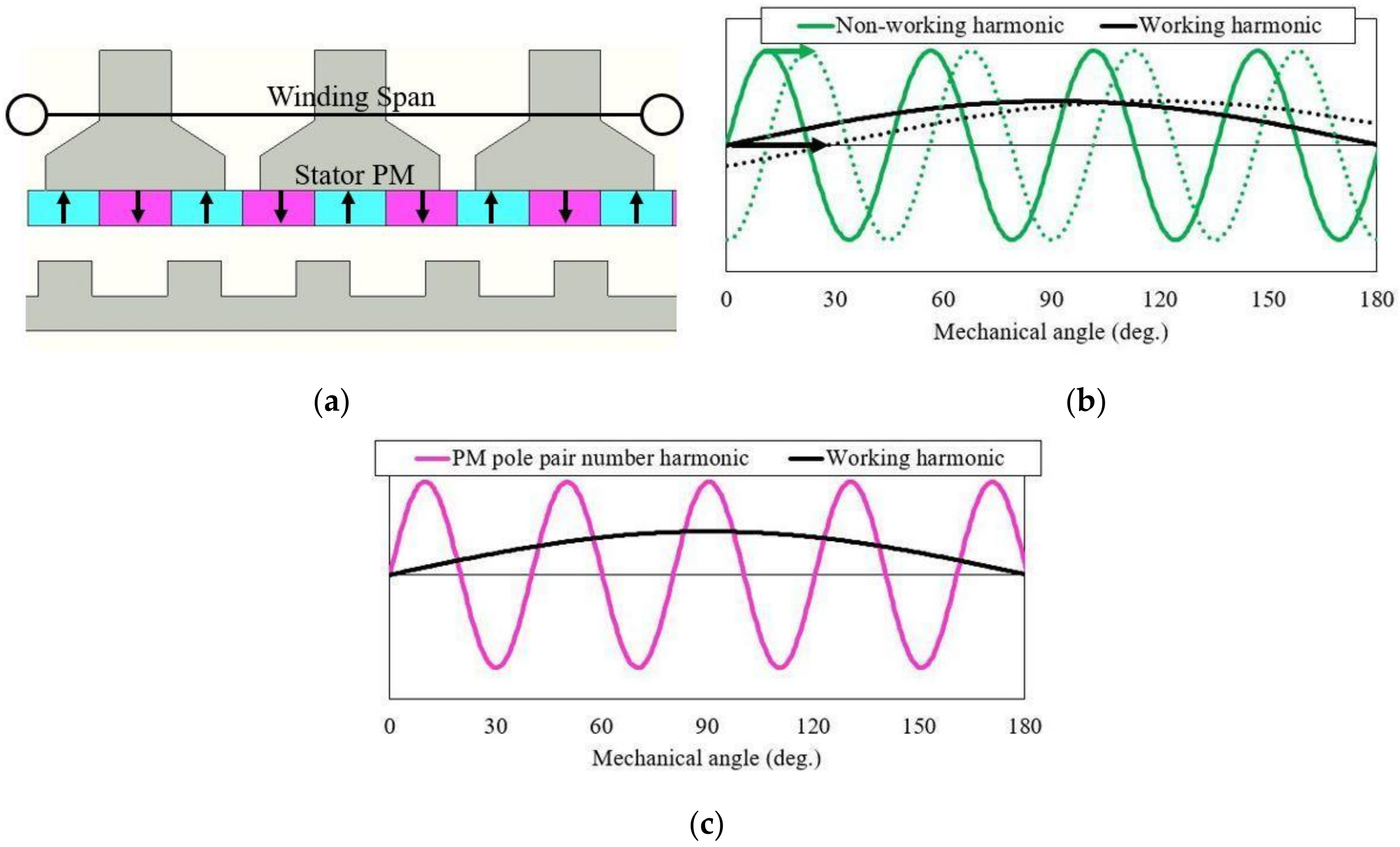
2.2. Working Harmonic Contribution Analysis

First, it is noticeable that stator PM Vernier machines work mostly by two working harmonic components: the main working harmonic, which is equal to the armature pole pair number, and the other working harmonics.
The relationship between the armature pole pair number and the PM pole pair number in Vernier machines can be expressed as
P a = P r P
where P a is the armature pole pair number.
Before determining the contribution of the working harmonics, it is important to clarify which harmonics are the working and nonworking ones.
To be considered working harmonics, they must contribute to the torque. To contribute to the torque, they must have an alternating integral quantity within the range of the winding span while the rotor rotates [32]. This can also be proved from Equations (11)–(13), where the alternating airgap flux density results in an alternating phase flux linkage, which eventually contributes to the back EMF and torque. The alternating integral quantity within the range of the winding span is depicted in Figure 2.
Figure 2a shows half of the machine in Figure 1a with a linear version. The winding span of the machine is 180°. Figure 2b,c is located on the same standard axis as in Figure 2a for a better understanding.
In Figure 2b, the nonworking and working harmonics are represented by solid lines. They move as the rotor rotates. The arrow describes the direction of harmonic movement with rotor rotation. The dotted line represents the resultant harmonic position after movement. Figure 2b shows that the integral quantity does not change with movement, and there is a nonworking harmonic. The other, however, decreases its integral quantity with movement. Therefore, it is a working harmonic.
In Figure 2c, the PM pole-pair-number harmonic and the working harmonic are shown simultaneously. Although the PM pole-pair-number harmonic is the source of all the resultant harmonics from the flux modulation, it is stationary because of the stator-positioned PMs. It does not move with the rotor rotation and, hence, does not contribute to torque production.
Among the working harmonics, the effective working harmonics are selected based on their magnitude and speed. This is because of the amount of the contribution to torque production. Because the magnitude is larger and the speed is faster, more contribution can be made to torque production. This statement can be verified from Equations (11)–(13) because the increased alternation rate of the airgap flux density contributes to the back EMF and, hence, the torque. Typically, the main working harmonic is the one that contributes the most. The other working harmonics are the harmonics with the next greatest contribution. The modulation poles in the stator PM Vernier machine are rotor iron poles. Other harmonics are negligible because they have almost no contribution compared with the main and by-product harmonics, mainly because of their low speed. The harmonic components are calculated from the airgap flux density using the fast Fourier transform. Additionally, the working harmonics are selected based on the interaction between number of PM pole pairs and rotor iron poles are the flux modulation. Hence, the equations in Table 1 are the most relevant harmonic orders to the flux modulation and work as working harmonics. This can be also seen in multiple previous studies [33,34,35]. The selected working harmonics are shown in Table 1 and Table 2.
As shown in Figure 2, the stator PM Vernier machine has stationary PMs on the stator part. Correspondingly, the PM pole-pair-number order harmonic does not have speed and, hence, has no contribution, and it is not included in Table 1 and Table 2. The working harmonics differ between rotor PM Vernier machines and stator PM Vernier machines. The main difference is that the rotor PM Vernier machine utilizes the PM pole-pair-number harmonic, whereas the stator PM Vernier machine does not [18].
The speed of the harmonic order P r P has the highest value, whereas the denominator of the speed has the lowest value. This is the main working harmonic because it mostly contributes to the torque. Hence, constructing a machine with an armature pole pair number equal to P r P is the most effective. In addition, as P r P decreases, the speed of the harmonic increases. These phenomena are the reasons for building Vernier machines to have combinations of Equation (14) and to achieve the lowest possible value for Equation (14).
The magnitude of the harmonics is determined by the PM MMF and permeance. The PM MMF and permeance are determined by machine parameters, such as the PM thickness, pole arc, stator slot opening, and rotor teeth width. The exact values of these elements require further calculation from other analytic methods, such as the magnetic equivalent circuit.
The average torque of each machine can be calculated using Equations (10)–(13). They can be expressed using the average torque elements as follows:
T v = t v 1 + t v 2 + t v 3 + t v 4 = 3 g   μ 0 r l N s I λ r 1 λ s v k P r + 3 g   2 μ 0 r l N s I λ r 1 P r n = 1 λ s v k P r ± n P P r ± n P + 3 g   2 μ 0 r l N s I λ r 1 λ s v P r j = 1 F v i k j P ± P r j P ± P r + 3 g   4 μ 0 r l N s I λ r 1 P r n = 1 j = 1 λ s v F q j k P r ± n P ± j P r P r ± n P ± j P r
T q = t q 1 + t q 2 + t q 3 + t q 4 = 3 g   μ 0 r l N s I λ r 1 λ s 0 F 0 k P r + 3 g   2 μ 0 r l N s I λ r 1 F 0 P r n = 1 λ s n k P r ± n P P r ± n P + 3 g   2 μ 0 r l N s I λ r 1 λ s 0 P r j = 1 F q j k j P ± P r j P ± P r + 3 g   4 μ 0 r l N s I λ r 1 P r n = 1 j = 1 λ s n F q j k P r ± n P ± j P r P r ± n P ± j P r
where I is the peak phase current. Based on these average torque elements, working-harmonic-related elements were selected, as shown in Table 1 and Table 2. Hence, the working harmonic contributions to the average torque can be simplified as
T = 3 r l N s I P r × B P r P   k P r P P r P + B P r + P   k P r + P P r + P + B 2 P r P   k 2 P r P 2 P r P + B 2 P r + P   k 2 P r + P 2 P r + P
Because the working harmonic orders are the same for conventional and consequent pole machines, the format of the average torque equation is the same for both machines. The airgap flux density values in Equation (17) are different.

2.3. Torque Enhancement

The consequent pole structure reduces the number of PMs by half by substituting one side of the pole into the iron pole. This provides a shorter airgap in the flux path and lower flux leakage, which eventually enhances the torque density [36]. These are well-known reasons for the torque enhancement of the consequent pole.
In stator PM Vernier machines, the consequent pole becomes more beneficial than the aforementioned features. The consequent pole machine has the PM pole-pair-number harmonic modulated into the working harmonics more than the conventional machine does. This is because of the substitution of iron poles from the consequent pole structure. The substituted iron poles act as modulation poles. First, the permeance of the stator in the consequent pole machine has an additional constant and different variables compared with those of the conventional machine, as shown in Equation (3).
To maximize the flux modulation effect, an armature pole pair number of 1 was selected [37]. A higher number of PMs results in a higher flux modulation effect and a high torque density. However, this results in a very low power factor if the PM number is too high. Hence, the PM pole pair number, which results in a reasonable power factor and has a reasonable torque density, was chosen. The specifications of the stator PM Vernier machine are listed in Table 3.
Second, the substituted iron poles in the consequent pole machine change the PM MMF compared with the conventional machine, as shown in Equations (6) and (7). An additional constant F_0 is added. The additional constants and variables in the stator permeance and PM MMF of the consequent pole machine result in more flux modulation compared with the conventional machine. These can be seen in Equations (8) and (9) because Equation (9) has more elements than Equation (8). This verifies that more flux modulation is performed in the consequent pole machine. Hence, increased harmonic values, including the main working harmonic value, are achieved, except for the PM pole-pair-number harmonic.
The adoption of the consequent pole reduces the PM number by half; hence, the PM pole-pair-number harmonic is halved. However, the PM pole-pair-number harmonic does not have a torque contribution in stator PM Vernier machines, as discussed in Section 2. Hence, a decrease in the PM pole pair number harmonic does not decrease the torque.
Eventually, by increasing the main working harmonic while decreasing one of the nonworking harmonic PM pole-pair-number harmonics, torque enhancement is achieved. Equations (15) and (16) reveal that the values of the elements are different for conventional and consequent pole machines. The constant values of the stator permeance, λ s v and λ s 0 , are the main difference. The torque of the consequent pole machine can be increased compared with the conventional machine as λ s 0   > λ s v .
The torque enhancement can be further proved by the finite-element method, showing the decrement of the PM pole-pair-number harmonic and the increment of the main working harmonic. In addition, a machine performance comparison of conventional and consequent pole machines can be performed, as discussed in a later section.

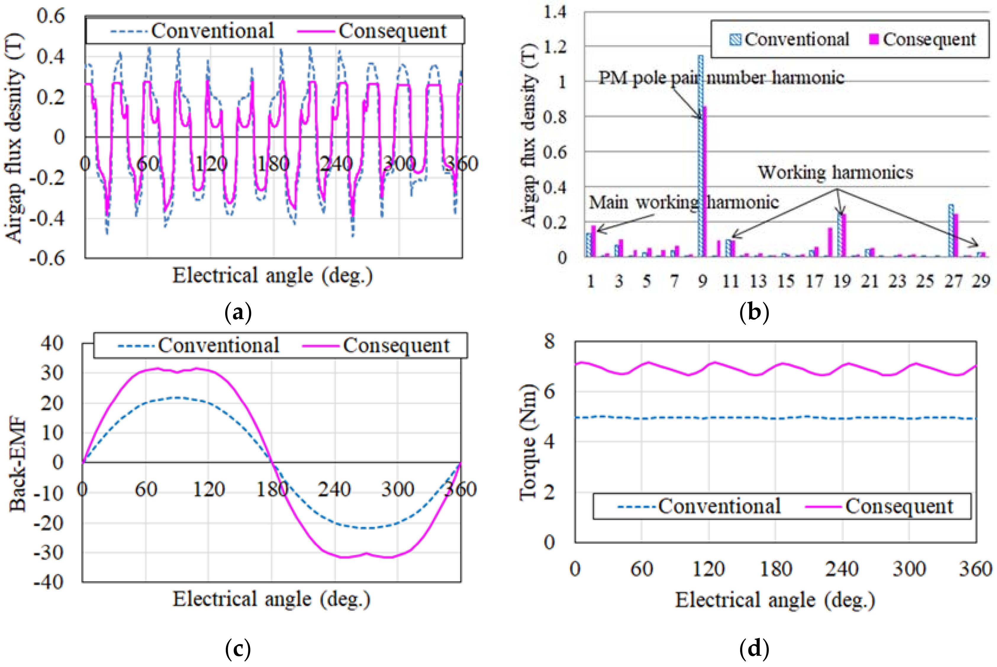
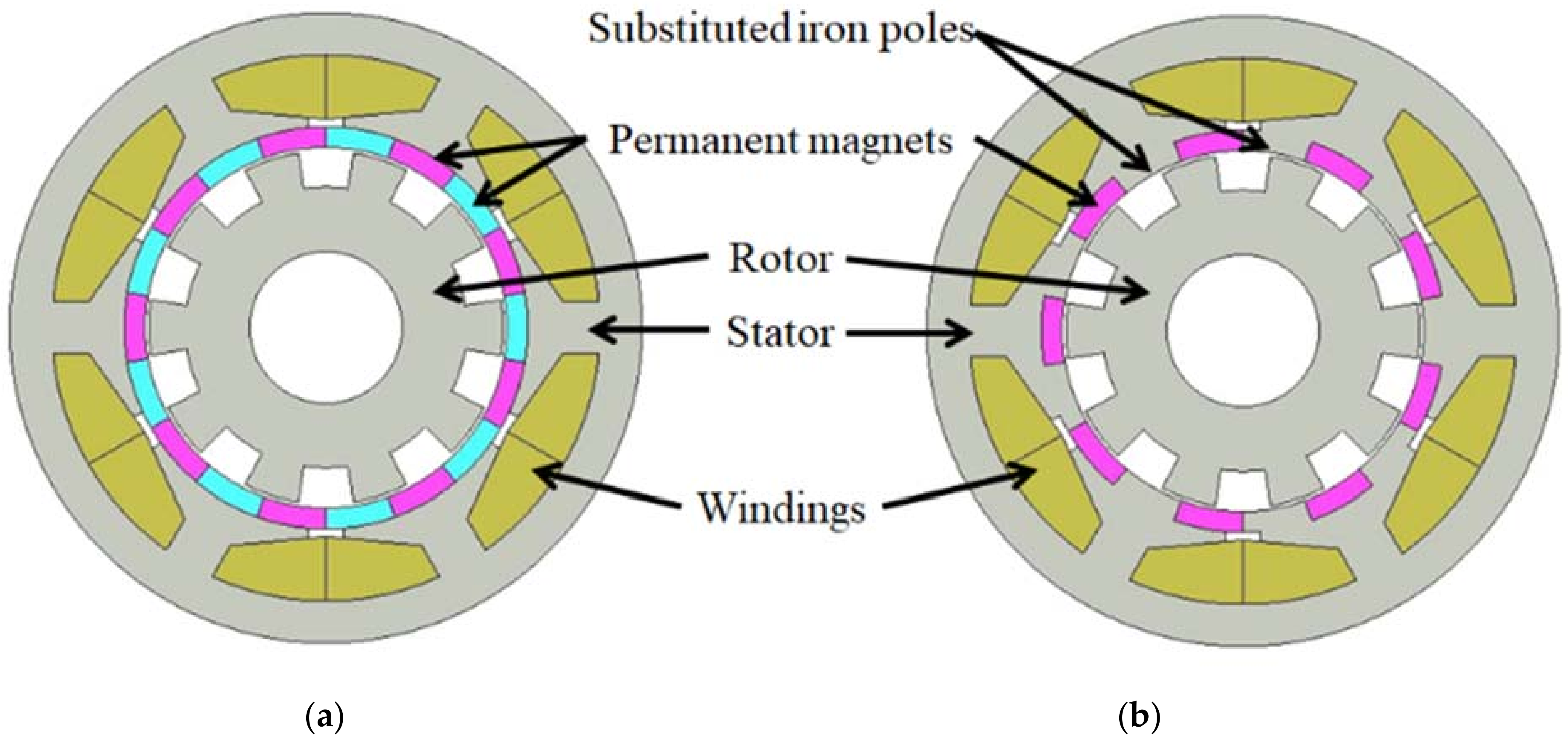
3. Principle Verification

To demonstrate the torque enhancement by the consequent pole structure in the stator PM Vernier machine, conventional and consequent pole machines of stator PM Vernier machines were designed and compared. The designed machines are shown in Figure 1.
To maximize the flux modulation effect, an armature pole pair number of 1 was selected [38]. A higher number of PMs results in a higher flux modulation effect and a high torque density. However, this results in a very low power factor if the PM number is too high. Hence, the PM pole pair number, which results in a reasonable power factor and has a reasonable torque density, was chosen. The specifications of the stator PM Vernier machine are listed in Table 4.
As shown in Figure 1, the only difference between the conventional machine and consequent pole machine is the substitution of PMs with iron poles.
The working harmonic contributions of each machine are provided in Table 4.
Because the consequent pole was adopted, the main working harmonic increased with a decrease in the number harmonic of the PM pole pair. Table 4 reveals that the torque contribution of the main working harmonic, P r P = P a , became larger after the consequent pole structure was adopted. Furthermore, other working harmonics decreased their contribution as flux modulation focused on the main working harmonic.
To show the absolute comparison of the harmonic components and the resultant machine performances, two finite-element method results are presented in Figure 3 and Table 4.
Figure 3a shows the airgap flux density waveform of each machine. In the figure, it appears that the consequent pole machine has a lower quantity than the conventional machine owing to its lower peak values. However, as Figure 3b shows, the main working harmonic of the consequent pole machine, which is the first, has increased compared with the conventional machine. One of the nonworking harmonics, the PM pole-pair-number harmonic, which is the ninth harmonic component, decreased as the PM number was halved compared with the conventional machine. However, the decrement did not affect the torque production because it did not contribute to the torque enhancement owing to its stationary character. As explained in Section 2.2, the harmonics must be moving. Hence, the harmonics that are multiples of the PM number are not considered as they are stationary on the stator. In addition, the working harmonics must have variation of integral quantity with movement in winding span. Considering all these conditions, nonworking harmonics are neglected from working harmonics. Figure 3c,d illustrates the enhancement of the back EMF and, hence, the enhancement of torque with the adoption of the consequent pole structure. This confirms that the increment in torque was caused by an increase in the main working harmonic, while there was no loss from the decrease in the PM pole-pair-number harmonic.
Table 5 lists the values of the overall machine performance. Even though the PMs decreased in volume after the adoption of the consequent pole, the machine achieved an increased torque compared with conventional machines. This was realized based on the torque enhancement principle. The power factor decreased slightly with the consequent pole machine compared with the conventional machine. However, the efficiency of the consequent pole was higher than that of the conventional machine owing to the decrease in PM loss and increase in power.

4. Conclusions

The torque enhancement principle of a stator PM Vernier machine with a consequent pole structure was investigated. The torque production equation was organized to demonstrate the torque enhancement principle and working harmonic contributions. The equations show that the consequent pole structure provides increased working harmonics and decreased nonworking harmonics and PM pole-pair-number harmonics.
The stator PM Vernier machine topology of the conventional and consequent pole machines was analyzed to verify the torque enhancement principle. From the analysis, the following conclusions were drawn. First, the main working harmonic increases dramatically with the adoption of the consequent pole structure. Second, the consequent pole in the stator PM Vernier machine inherently decreases the PM pole-pair-number harmonic when the PM number is halved. Finally, the consequent pole machine of the stator PM Vernier machine has a significantly higher torque than the conventional machine. This was because the main working harmonic increased and the nonworking harmonic decreased.

Author Contributions

Conceptualization, J.-W.K.; methodology, J.-W.K.; validation, J.-W.K. and B.-I.K.; formal analysis, J.-W.K.; investigation, J.-W.K.; resources, J.-W.K.; data curation, J.-W.K.; writing—original draft preparation, J.-W.K.; writing—review and editing, J.-W.K. and B.-I.K.; visualization, J.-W.K.; supervision, B.-I.K.; project administration, J.-W.K.; funding acquisition, B.-I.K. All authors have read and agreed to the published version of the manuscript.

Funding

This research was funded by the National Research Foundation of Korea (NRF) grant funded by the Korea government (MSIT) (No. NRF-2020R1A2B5B01002400).

Conflicts of Interest

The authors declare no conflict of interest.

References

  1. Wu, F.; El-Refaie, A.M. Permanent magnet vernier machine: A review. IET Electr. Power Appl. 2019, 13, 127–137. [Google Scholar] [CrossRef]
  2. Li, J.; Chau, K.T.; Jiang, J.Z.; Liu, C.; Li, W. A New Efficient Permanent-Magnet Vernier Machine for Wind Power Generation. IEEE Trans. Magn. 2010, 46, 1475–1478. [Google Scholar] [CrossRef]
  3. Jang, D.; Chang, J.H. Design of a Vernier Machine with PM on Both Sides of Rotor and Stator. IEEE Trans. Magn. 2014, 50, 877–880. [Google Scholar] [CrossRef]
  4. Shi, C.; Li, D.; Qu, R.; Zhang, H.; Gao, Y.; Huo, Y. A Novel Linear Permanent Magnet Vernier Machine with Consequent-Pole Permanent Magnets and Halbach Permanent Magnet Arrays. IEEE Trans. Magn. 2017, 53, 1–4. [Google Scholar] [CrossRef]
  5. Baloch, N.; Kwon, B.-I.; Gao, Y. Low-Cost High-Torque-Density Dual-Stator Consequent-Pole Permanent Magnet Vernier Machine. IEEE Trans. Magn. 2018, 54, 1–5. [Google Scholar] [CrossRef]
  6. Gorginpour, H. Dual-stator consequent-pole Vernier PM motor with improved power factor. IET Electr. Power Appl. 2019, 13, 652–661. [Google Scholar] [CrossRef]
  7. Chung, S.-U.; Kim, J.-W.; Woo, B.-C.; Hong, D.-K.; Lee, J.-Y.; Koo, D.-H. A Novel Design of Modular Three-Phase Permanent Magnet Vernier Machine with Consequent Pole Rotor. IEEE Trans. Magn. 2011, 47, 4215–4218. [Google Scholar] [CrossRef]
  8. Toba, A.; Lipo, T.A. Generic torque-maximizing design methodology of surface permanent-magnet vernier machine. IEEE Trans. Ind. Appl. 2000, 36, 1539–1546. [Google Scholar]
  9. Cheng, M.; Chau, K.T.; Chan, C.C. Static characteristics of a new doubly salient permanent magnet motor. IEEE Trans. Energy Convers. 2001, 16, 20–25. [Google Scholar] [CrossRef] [Green Version]
  10. Chau, K.T.; Sun, Q.; Fan, Y.; Cheng, M. Torque Ripple Minimization of Doubly Salient Permanent-Magnet Motors. IEEE Trans. Energy Convers. 2005, 20, 352–358. [Google Scholar] [CrossRef] [Green Version]
  11. More, D.S.; Fernandes, B.G. Analysis of Flux-Reversal Machine Based on Fictitious Electrical Gear. IEEE Trans. Energy Convers. 2010, 25, 940–947. [Google Scholar] [CrossRef]
  12. Gao, Y.; Qu, R.; Li, D.; Li, J.; Huo, Y. Design and analysis of a novel flux reversal machine. In Proceedings of the 2016 IEEE Energy Conversion Congress and Exposition (ECCE), Milwaukee, WI, USA, 18–22 September 2016; pp. 1–8. [Google Scholar]
  13. Kim, T.H.; Lee, J. A Study of the Design for the Flux Reversal Machine. IEEE Trans. Magn. 2004, 40, 2053–2055. [Google Scholar] [CrossRef]
  14. Chen, J.T.; Zhu, Z.Q. Winding Configurations and Optimal Stator and Rotor Pole Combination of Flux-Switching PM Brushless AC Machines. IEEE Trans. Energy Convers. 2009, 25, 293–302. [Google Scholar] [CrossRef]
  15. Hua, W.; Cheng, M.; Zhu, Z.; Howe, D. Analysis and Optimization of Back EMF Waveform of a Flux-Switching Permanent Magnet Motor. IEEE Trans. Energy Convers. 2008, 23, 727–733. [Google Scholar] [CrossRef]
  16. Chen, J.T.; Zhu, Z.Q.; Iwasaki, S.; Deodhar, R. A novel E-core flux-switching PM brushless AC machine. In Proceedings of the 2010 IEEE Energy Conversion Congress and Exposition, Atlanta, GA, USA, 12–16 September 2010; pp. 3811–3818. [Google Scholar]
  17. Shao, L.; Hua, W.; Zhu, Z.Q.; Zhu, X.; Cheng, M.; Wu, Z. A Novel Flux-Switching Permanent Magnet Machine with Overlapping Windings. IEEE Trans. Energy Convers. 2016, 32, 172–183. [Google Scholar] [CrossRef]
  18. Liu, X.; Zou, C.; Du, Y.; Xiao, F. A linear consequent pole stator permanent magnet vernier machine. In Proceedings of the 2014 17th International Conference on Electrical Machines and Systems (ICEMS), Hangzhou, China, 22–25 October 2014. [Google Scholar]
  19. Tao, W.; Zhou, H.; Liu, G. A Novel Stator-PM Vernier Fault-Tolerant Machine with Consequent Pole Structure. In Proceedings of the 2019 22nd International Conference on Electrical Machines and Systems (ICEMS), Harbin, China, 11–14 August 2019. [Google Scholar]
  20. Jia, S.; Qu, R.; Li, J.; Li, D.; Kong, W. A Stator-PM Consequent-Pole Vernier Machine with Hybrid Excitation and DC-Biased Sinusoidal Current. IEEE Trans. Magn. 2017, 53, 1–4. [Google Scholar] [CrossRef]
  21. Yang, H.; Zhu, Z.Q.; Lin, H.; Li, H.Y.; Lyu, S. Analysis of Consequent-Pole Flux Reversal Permanent Magnet Machine with Biased Flux Modulation Theory. IEEE Trans. Ind. Electron. 2020, 67, 2107–2121. [Google Scholar] [CrossRef]
  22. Botha, C.D.; Kamper, M.J.; Wang, R.-J.; Chama, A. Analytical Modeling of Surface-Mounted and Consequent-Pole Linear Vernier Hybrid Machines. IEEE Access 2021, 9, 26251–26259. [Google Scholar] [CrossRef]
  23. Almoraya, A.A.; Baker, N.J.; Smith, K.J.; Raihan, M.A.H. Development of a double-sided consequent pole linear vernier hybrid permanent-magnet machine for wave energy converters. In Proceedings of the 2017 IEEE International Electric Machines and Drives Conference (IEMDC), Miami, FL, USA, 21–24 May 2017. [Google Scholar]
  24. Botha, C.; Kamper, M.; Wang, R.-J.; Sorgdrager, A. Force Ripple and Cogging Force Minimisation Criteria of Single-Sided Consequent-Pole Linear Vernier Hybrid Machines. In Proceedings of the 2020 International Conference on Electrical Machines (ICEM), Gothenburg, Sweden, 23–26 August 2020; Volume 1. [Google Scholar]
  25. Liu, W.; Lipo, T.A. Analysis of Consequent Pole Spoke Type Vernier Permanent Magnet Machine with Alternating Flux Barrier Design. IEEE Trans. Ind. Appl. 2018, 54, 5918–5929. [Google Scholar] [CrossRef]
  26. Yang, H.; Lin, H.; Zhu, Z.-Q.; Fang, S.; Huang, Y. A Dual-Consequent-Pole Vernier Memory Machine. Energies 2016, 9, 134. [Google Scholar] [CrossRef]
  27. Li, D.; Qu, R.; Li, J.; Xu, W. Consequent-Pole Toroidal-Winding Outer-Rotor Vernier Permanent-Magnet Machines. IEEE Trans. Ind. Appl. 2015, 51, 4470–4481. [Google Scholar] [CrossRef]
  28. Heller, B.; Hamata, V. Harmonic Field Effects in Induction Machines; Elsevier: Amsterdam, The Netherlands, 1977. [Google Scholar]
  29. Li, D.; Qu, R.; Li, J.; Xu, W.; Wu, L. Synthesis of Flux Switching Permanent Magnet Machines. IEEE Trans. Energy Convers. 2015, 31, 106–117. [Google Scholar] [CrossRef]
  30. Zhu, Z.Q.; Howe, D. Instantaneous magnetic field distribution in brushless permanent magnet DC motors. III. Effect of stator slotting. IEEE Trans. Magn. 1993, 29, 143–151. [Google Scholar] [CrossRef]
  31. Li, Y.; Yang, H.; Lin, H. Comparative Study of Torque Production Mechanisms in Stator and Rotor Consequent-Pole Permanent Magnet Machines. IEEE Trans. Transp. Electrif. 2021, 7, 2694–2704. [Google Scholar] [CrossRef]
  32. Kim, B. Design of a PM Vernier Machine with Consideration for Modulation Flux and Comparison with Conventional PM motors. Energies 2017, 10, 1819. [Google Scholar] [CrossRef] [Green Version]
  33. Li, D.; Qu, R.; Li, J. Topologies and analysis of flux-modulation machines. In Proceedings of the 2015 IEEE Energy Conversion Congress and Exposition (ECCE), Montreal, QC, Canada, 20–24 September 2015. [Google Scholar]
  34. Zou, T.; Li, D.; Chen, C.; Qu, R.; Jiang, D. A Multiple Working Harmonic PM Vernier Machine with Enhanced Flux-Modulation Effect. IEEE Trans. Magn. 2018, 54, 1–5. [Google Scholar] [CrossRef]
  35. Zou, T.; Li, D.; Qu, R.; Jiang, D.; Li, J. Advanced High Torque Density PM Vernier Machine with Multiple Working Harmonics. IEEE Trans. Ind. Appl. 2017, 53, 5295–5304. [Google Scholar] [CrossRef]
  36. Allahyari, A.; Torkaman, H. A Novel High-Performance Consequent Pole Dual Rotor Permanent Magnet Vernier Machine. IEEE Trans. Energy Convers. 2020, 35, 1238–1246. [Google Scholar] [CrossRef]
  37. Du, Y.; Chau, K.T.; Cheng, M.; Fan, Y.; Wang, Y.; Hua, W.; Wang, Z. Design and Analysis of Linear Stator Permanent Magnet Vernier Machines. IEEE Trans. Magn. 2011, 47, 4219–4222. [Google Scholar] [CrossRef]
  38. Liu, G.; Yang, J.; Zhao, W.; Ji, J.; Chen, Q.; Gong, W. Design and Analysis of a New Fault-Tolerant Permanent-Magnet Vernier Machine for Electric Vehicles. IEEE Trans. Magn. 2012, 48, 4176–4179. [Google Scholar] [CrossRef]
Figure 1. Stator PM Vernier machine: (a) conventional machine and (b) consequent pole machine.
Energies 15 02993 g001
Figure 2. (a) Winding span. (b) Nonworking harmonic and working harmonic movement. (c) PM pole-pair-number harmonic with no movement.
Energies 15 02993 g002
Figure 3. Machine performance comparison: (a) Airgap flux density. (b) Magnitudes of harmonics. (c) Back-EMF. (d) Torque.
Energies 15 02993 g003
Table 1. Working harmonic magnitude and speed of the conventional machine.
Harmonic OrderMagnitudeSpeed
P r P = P a g   2 μ 0 F v 1 λ r 1 λ s 0 P r Ω P r P
P r + P g   2 μ 0 F v 1 λ r 1 λ s 0 P r Ω P r + P
2 P r P g   2 μ 0 F v 2 λ r 1 λ s 0 P r Ω 2 P r P
2 P r + P g   2 μ 0 F v 2 λ r 1 λ s 0 P r Ω 2 P r + P
Table 2. Working harmonic magnitude and speed of the consequent pole machine.
Harmonic OrderMagnitudeSpeed
P r P = P a g   2 μ 0 F 0 λ r 1 λ s 1 + g   2 μ 0 F q 1 λ r 1 λ s 0 P r Ω P r P
P r + P g   2 μ 0 F 0 λ r 1 λ s 1 + g   2 μ 0 F q 1 λ r 1 λ s 0 P r Ω P r + P
2 P r P g   2 μ 0 F 0 λ r 1 λ s 2 + g   2 μ 0 F q 2 λ r 1 λ s 0 P r Ω 2 P r P
2 P r + P g   2 μ 0 F 0 λ r 1 λ s 2 + g   2 μ 0 F q 2 λ r 1 λ s 0 P r Ω 2 P r + P
Table 3. Specification of the stator PM Vernier machine.
ItemUnitValue
Stator slot-6
Rotor pole pair-10
Stator pole pair-9
Armature pole pair-1
Stator outer diametermm166
Stator inner diametermm106
Rotor outer diametermm92
Thickness of magnetmm6
Stack lengthmm90
Airgap lengthmm1
Turns per phase-100
Material of stator and rotor core-35H440
Material of magnet-NdFeB
Table 4. Working harmonic contributions.
ItemUnitConventionalConsequent
P r P = P a %77.6116.4
P r + P %28.427
2 P r P %−27.7−51.8
2 P r + P %7.16.7
Table 5. FEM analysis results.
ItemUnitConventionalConsequent
Back EMFV16.225.2
Average torqueNm4.956.88
PM volumemm379,51639,758
Torque per PM volumeNm/mm30.000150.00040
Power factor-0.820.78
PowerW259360
Iron lossW17.429.8
PM lossW28.216.5
Efficiency%85.188.6
Publisher’s Note: MDPI stays neutral with regard to jurisdictional claims in published maps and institutional affiliations.

